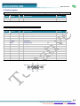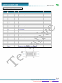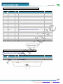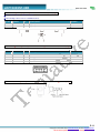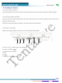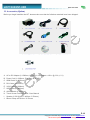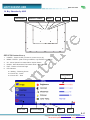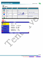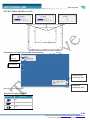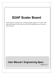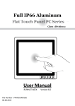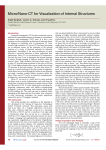
1
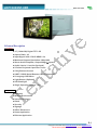
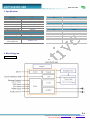
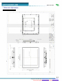
FLAT DISPLAY TECHNOLOGY
product
is RoHS compliant
This productThis
is RoHS
compliant
§ SPECIFICATION APPROVAL SHEET §
LOF150X35P-00R
15” Digital TFT-LCD Module
SAS-1411002
0.0
December 1, 2014
※ This approval sheet contains 21 pages including the cover and appendix.
14
Copyright © 2014 FLAT Display Technology Corporation. All rights reserved.
Add: No.85, Sec. 1, Fuxing Rd., South Dist., Taichung City 402, Taiwan (R.O.C.) http:// www.fdt.com.tw E-mail: [email protected]
Tel: 886-4-22619577, Fax: 886-4-22623978
LOF150X35P-00R
2014 12 01 V0.0
1.General Description
1.1 Features
■ 15” (1024x768) Digital TFT LCD
■ Aspect Ratio: 4:3
■ Input Signal VGA / DVI-D/ HDMI 1.3a
■ Maximum Support Resolution 1920x1080
■ Stereo Audio Amplifier, Output 2W@4Ω Speaker
■ Audio Line-In / Line-Out (Optional)
■ 2 Points Projected Capacitive Touch
■ 5 Key Buttons Control
■ UART / RS232 Serial Remote Control (Optional)
■ 8 Language OSD Menu
■ Light Sensor (Optional)
■ LED Backlight
■ Single Operation Voltage +12V
1.2 Applications
■ Industrial
■ Medical Environment
■ Instrument Display
■ Kiosk
■ Security
■ Signage
■ Office Electronics
■ Home Application
■ Educate Application
P.1
Copyright © 2014 FDT http:// www.fdt.com.tw, E-mail- [email protected]
This technical specification is subject to change without notice
LOF150X35P-00R
2014 12 01 V0.0
2. Contents
Page
Contents
1. General Description…………………………………………………………………………………….…………….
1
1.1 Features
1
1.2 Applications
1
2.Contents……………….……………………………………………………………...…………………………….….
2-3
3 .Specifications………..………………………………………….………………..……………………………………
4
4. Black Diagram………………………………………………………………….………………………………….….
4
4.1 Black Diagram
4
5. TFT-LCD Information………………………………………………………………………………….…………….
5
5.1 TFT-LCD Mechanical Specifications
5
5.2 TFT-LCD Optical Characteristics
5
6. Order Information…..………………...………………………………………………………………………………
6.1 Unit
6
6
7. Dimension Information……………………………………………………………………………………………….
7.1 Unit (LOF150X35P-00R)
7
7
8. Pin Description………………………………………………………………………………………………………..
8-11
8.1 DC-In : Pin Assignment of Power Input (DC Jack Inside Diameter:2.1ψ Outside Diameter:5.5ψ Side Entry Type)
8
8.2 VGA : Pin Assignment of Analog RGB Input ( D-Sub 15Pin)
8
8.3 DVI:Pin Assignment of DVI-D (24 Pin)
9
8.4 HDMI:Pin Assignment of HDMI-A Type Input (HDMI 1.3a -19Pin Female)
10
8.5 L:Pin Assignment of Spear Left (Pitch 2.0mm 2Pin , Top Entry Type)
10
8.6 R : Pin Assignment of Spear Right (Pitch 2.0mm 2Pin , Top Entry Type)
11
8.7 USB Port:Pin Assignment of Touch USB (USB A Type - Female 2.0mm, Side Entry Type )
11
8.8 Line-In:Pin Assignment of Line-In/Out (Option) (Outside Diameter:3.5ψSide Entry Type)
11
9. Absolute Maximum Ratings………………………………………………………………………………...………...
9.1 Absolute Maximum Ratings
12
12
10. Recommended Operating Conditions……………………………………………………………………...………
12
10.1 Electrical Characteristics
12
10.2 VGA Mode Characteristics
12
11. Projected Capacitive Touch Panel Characteristics…………………………………………………………………
13-14
11.1 Electrical Performance
13
11.2 Optical Performance
13
11.3 Mechanical Performance
13
11.4 Touch Panel Operation System Support
13
11.5 Panel Mount Installation (Mount Clamp and Screw)
14
12. Installing the Monitor……………………………………………………………………………………………….
12.1 Power cable connection
15
15
P.2
Copyright © 2014 FDT http:// www.fdt.com.tw, E-mail- [email protected]
This technical specification is subject to change without notice
LOF150X35P-00R
2014 12 01 V0.0
12.2 VGA signal cable connection
15
12.3 Switch on the power
15
13. Accessories (Option)………………………………………………………………………………………………..
14. Key Function by OSD………………………………………………………………………………………………..
14.1 Menu Operation
16
17-20
17-20
P.3
Copyright © 2014 FDT http:// www.fdt.com.tw, E-mail- [email protected]
This technical specification is subject to change without notice
LOF150X35P-00R
2014 12 01 V0.0
3. Specifications
LCD
Panel Size
Resolution (Pixels)
Color
Luminance w/o TP
15”
1024x768
16.7M
400 cd/㎡
Input Signal
VGA
DVI
HDMI
Audio
D-Sub15
DVI-D
1.3a
Luminance (PCT)
348 cd/㎡
Amplifier
1W@8Ω / 2W@4Ω
Contrast Ratio
Viewing Angle
Backlight Life Time (LED)
Power Requirement
Power Input (DC Jack 2.1ψ)
700
80 / 80 / 70 / 70
50K (Min)
Line-In
Controls
Key
Serial Remote Control
Environment
Operating Temp. PCT
Storage Temp. PCT
Stereo Input Phone Jackψ3.5
PowerConsumption@+12V
Touch Screen
Projected Capacitive Touch
Projected Capacitive
Touch Support OS
+12 VDC
11.4 Watts (@Without Amplifier)
5 Buttons
UART / RS232 (Optional)
-20 ~ +70℃
-20 ~ +70℃
USB Interface ( 2 Points )
Windows / Linux
4. Block Diagram
4.1 Block Diagram
P.4
Copyright © 2014 FDT http:// www.fdt.com.tw, E-mail- [email protected]
This technical specification is subject to change without notice
LOF150X35P-00R
2014 12 01 V0.0
5. TFT-LCD Information
5.1 TFT-LCD Mechanical Specifications
Parameter
Specifications
Unit
Screen Size
15 (diagonal)
Inch
1024 x (R.G.B) x 768
Dot
Active Area
304.1(H) x 228.1(V)
mm
Pixel Pitch
0.297(H) x 0.297(V)
mm
Pixel Arrangement
RGB vertical stripe
Surface Treatment
Anti-Glare, Haze=25%, Hard Coating (3H)
Display Format
5.2 TFT-LCD Optical Characteristics
Parameter
Symbol
Horizontal
Viewing Angle
Vertical
Contrast Ratio
Luminance w/o PCT
LED Life Time (LED)
Left
Right
Top
Condition
CR >10
Bottom
CR
At optimized
Viewing angle
L
25℃
Min
Typ
Max
Unit
70
70
80
80
-----
deg
deg
55
70
---
deg
60
70
---
deg
450
700
---
---
300
400
---
cd/㎡
50000
---
---
Hrs
Remark
P.5
Copyright © 2014 FDT http:// www.fdt.com.tw, E-mail- [email protected]
This technical specification is subject to change without notice
LOF150X35P-00R
2014 12 01 V0.0
6. Order Information
6.1 Unit
Parameter
LOF150X35P-00R
VGA
◎
DVI
◎
HDMI
◎
Touch Panel Type
Projected Capacitive Touch
Touch Screen Interface
USB
Audio Amplifier
◎
Audio Line-In
◎
5 Keys
◎
UART Remote Control
◎
Note: 1.The assembling of panel and bracket is aimed for delivery, packaging and experiment. If the demand of shockproof and long-term fix, pls have it into
consideration of mechanism design.
Optional Functions
- Audio Line-Out
Parameter
- RS232 Remote Control
- Light Sensor
- Accessories (Option)
P.6
Copyright © 2014 FDT http:// www.fdt.com.tw, E-mail- [email protected]
This technical specification is subject to change without notice
LOF150X35P-00R
2014 12 01 V0.0
7. Dimension Information
7.1 Unit (LOF150X35P-00R)
P.7
Copyright © 2014 FDT http:// www.fdt.com.tw, E-mail- [email protected]
This technical specification is subject to change without notice
LOF150X35P-00R
2014 12 01 V0.0
8. Pin Description
8.1 DC-In : Pin Assignment of Power Input (DC Jack Inside Diameter:2.1ψ Outside Diameter:5.5ψ Side Entry Type)
Pin No. Symbol
I/O
Description
1
DC-IN
I
+12Vdc Input Voltage
2
GND
-
Power Ground
Remark
8.2 VGA : Pin Assignment of Analog RGB Input ( D-Sub 15Pin)
Pin No. Symbol
I/O
Description
1
RI+
I
Analog Red Signal
2
GI+
I
Analog Green Signal
3
BI+
I
Analog Blue Signal
4
GND
-
Ground
5
VGA-Det
I
VGA Detect
6
AGND
-
Analog Ground
7
AGND
-
Analog Ground
8
AGND
-
Analog Ground
9
VGA5V
-
VGA +5V Input
10
GND
-
Ground
11
GND
-
Ground
12
VGA_SDA
-
DDC2 Data
13
HS_IN
I
TTL Horizontal sync.
14
VS_IN
I
TTL Vertical sync.
15
VGA_SCL
-
DDC2 Clock
Remark
P.8
Copyright © 2014 FDT http:// www.fdt.com.tw, E-mail- [email protected]
This technical specification is subject to change without notice
LOF150X35P-00R
2014 12 01 V0.0
8.3 DVI:Pin Assignment of DVI-D (24 Pin)
Pin No. Symbol
I/O
Description
1
I
Negative DVI Input for A Link Data Channel 2
DATA2-
Remark
2
DATA2+
I
Positive DVI Input for A Link Data Channel 2
3
GND
-
Ground
4
NC
-
No Connection
5
NC
-
No Connection
6
DVI_SCL
I
DDC2 Clock
7
DVI_SDA
I
DDC2 Data
8
NC
-
No Connection
9
DATA1-
I
Negative DVI Input for A Link Data Channel 1
10
DATA1+
I
Positive DVI Input for A Link Data Channel 1
11
GND
-
Ground
12
NC
-
No Connection
13
NC
-
No Connection
14
DVI5V
I
DVI +5V Input
15
DET_DVI
I
DVI Detect
16
DVI_HPD
-
Hot Plug Detect
17
DATA0-
I
Negative DVI Input for A Link Data Channel 0
18
DATA0+
I
Positive DVI Input for A Link Data Channel 0
19
GND
-
Ground
20
NC
-
No Connection
21
NC
-
No Connection
22
GND
-
Ground
23
DCLK+
I
Positive DVI Input for A Link Clock Channel
24
DCLK-
I
Negative DVI Input for A Link Clock Channel
P.9
Copyright © 2014 FDT http:// www.fdt.com.tw, E-mail- [email protected]
This technical specification is subject to change without notice
LOF150X35P-00R
2014 12 01 V0.0
8.4 HDMI:Pin Assignment of HDMI-A Type Input (HDMI 1.3a -19Pin Female)
Pin No. Symbol
I/O
Description
1
I
Positive HDMI Input for B Link Data Channel 2
DATA2+
Remark
2
DET_HDMI
-
HDMI Detect
3
DATA2-
I
Negative HDMI Input for B Link Data Channel 2
4
DATA1+
I
Positive HDMI Input for B Link Data Channel 1
5
GND
-
Ground
6
DATA1-
I
Negative HDMI Input for B Link Data Channel 1
7
DATA0+
I
Positive HDMI Input for B Link Data Channel 0
8
GND
-
Ground
9
DATA0-
I
Negative HDMI Input for B Link Data Channel 0
10
DCLK+
I
Positive HDMI Input for B Link Clock Channel
11
GND
-
Ground
12
DCLK-
I
Negative HDMI Input for B Link Clock Channel
13
NC
-
No Connection
14
NC
-
No Connection
15
HDMI_SCL
I
DDC2 Clock
16
HDMI_SDA
I
DDC2 Data
17
GND
I
DDC/CEC Ground
18
HDMI5V
I
HDMI +5V Input
19
HDMI_HPD
I
Hot Plug Detect
8.5 L:Pin Assignment of Spear Left (Pitch 2.0mm 2Pin , Top Entry Type)
※ FDT Connector Part No.: A2001WV2-2P(JWT) ;
※ FDT Matching Connector Part No.: A2001H02-2P(JWT) .
Pin No. Symbol
I/O
Description
1
+LOUT
O
Left Speaker Out+
2
-LOUT
O
Left Speaker Out -
Remark
P.10
Copyright © 2014 FDT http:// www.fdt.com.tw, E-mail- [email protected]
This technical specification is subject to change without notice
LOF150X35P-00R
2014 12 01 V0.0
8.6 R : Pin Assignment of Spear Right (Pitch 2.0mm 2Pin , Top Entry Type)
※ FDT Connector Part No.: A2001WV2-2P(JWT) ;
※ FDT Matching Connector Part No.: A2001H02-2P(JWT) .
Pin No. Symbol
I/O
Description
1
+ROUT
O
Right Speaker Out+
2
-ROUT
O
Right Speaker Out-
Remark
8.7 USB Port:Pin Assignment of Touch USB (USB A Type - Female 2.0mm, Side Entry Type )
Pin No. Symbol
I/O
Description
1
VBUS
-
USB VCC
2
D-
-
DATA (-)
3
D+
-
DATA (+)
4
DGND
-
Digital Ground
Remark
8.8 Line-In:Pin Assignment of Line-In/Out (Option) (Outside Diameter:3.5ψSide Entry Type)
P.11
Copyright © 2014 FDT http:// www.fdt.com.tw, E-mail- [email protected]
This technical specification is subject to change without notice
LOF150X35P-00R
2014 12 01 V0.0
9. Absolute Maximum Ratings
9.1 Absolute Maximum Ratings
Parameter
Symbol
Input Voltage
Analog RGB Input Signal
Min
Max
Unit
Remark
Vin
11
13.5
V
Analog RGB in
0.5
2.0
Vp-p
TTL
Digital Input Signal
-0.3
3.6
V
DVI Input Signal
-
165
MHz
HDMI Input Signal
-
165
MHz
1.8
Vp-p
Operating Temp.
-20
+70
℃
Storage Temp.
-20
+70
℃
Line-in
10. Recommended Operating Conditions
10.1 Electrical Characteristics
Parameter
Symbol
I/O
Min
Typ
Max
Unit
11.5
12
13
V
Note
Input Voltage
DC-in
I
Total Current
I-in
I
950
mA
+12V
I
11.4
W
@Without
Amplifier
Power Consumption
Output Voltage
Analog RGB Input Signal
O
VDD
Analog RGB in
RGB
3.3
3.2
I
3.4
0.7
V
Vp-p
DVI Input Signal
165
MHz
HDMI Input Signal
165
MHz
@75Ω
10.2 VGA Mode Characteristics
Dots per inch
H
Unit
Polarity
V
Unit
Polarity
640 x 480
800 x 600
31.47
37.88
KHz
KHz
Positive
Positive
59.9
60.3
Hz
Hz
Positive
Positive
1024 x 768
48.36
KHz
Positive
60
Hz
Positive
1280 × 1024
63.98
KHz
Positive
60
Hz
Positive
1600 × 1200
75
KHz
Positive
60
Hz
Positive
1920 × 1080
67.5
KHz
Positive
60
Hz
Positive
Note
P.12
Copyright © 2014 FDT http:// www.fdt.com.tw, E-mail- [email protected]
This technical specification is subject to change without notice
LOF150X35P-00R
2014 12 01 V0.0
11. Projected Capacitive Touch Panel Characteristics
11.1 Electrical Performance
Parameter
Symbol
Input Voltage
Response Time
Min
Typ
Max
-
-
5V
25
-
30
Unit
Note
ms
11.2 Optical Performance
Parameter
Specifications
Light Transmittance
≧87%
11.3 Mechanical Performance
Parameter
Input Method
Touch Function
Interface
Surface Hardness
Cover Spec.
Specifications
Stylus for PCAP or Finger Available
2 Points
USB
≧6H
Chemically strengthened T=1.8mm Black Printing
11.4 Touch Panel Operation System Support
OS
Version
Interface
Windows 7 / Windows 9x_ME
Windows NT4.0
Windows
Windows CE6.0
USB
Windows CE7.0
Windows CE.Net_4.x / 5.0
Kernel 2.4.x (x86 32bits)
Linux
Kernel 2.6.23 Downward (x86 32 / 64bits)
USB
Kernel 2.6.24 Upwards (x86 32 / 64bits,ARM / MIPS )
P.13
Copyright © 2014 FDT http:// www.fdt.com.tw, E-mail- [email protected]
This technical specification is subject to change without notice
LOF150X35P-00R
2014 12 01 V0.0
11.5 Panel Mount Installation (Mount Clamp and Screw)
P.14
Copyright © 2014 FDT http:// www.fdt.com.tw, E-mail- [email protected]
This technical specification is subject to change without notice
LOF150X35P-00R
2014 12 01 V0.0
12. Installing the Monitor
12.1 Power cable connection:
Connect the power cord to the AC outlet, and connect the power to the monitor through the AC/DC adapter.
12.2 VGA signal cable connection:
Plug one end of the 15-pin signal cable to the VGA connector at the rear of the PC system and the other end to
the Open Frame monitor.
Secure the connectors with the screws on the cable connector at both ends.
12.3 Switch on the power:
Switch on the power switch on the rear cover of the Open Frame Monitor.
A
B
C
D
E
F
A. DC-In (+12VDC The DC jack core is positive)
B. Line-In : Phone Jackψ3.5
C. VGA D-sub 15 (Female)
D. DVI
E. HDMI
F. USB (For Touch Controller)
P.15
Copyright © 2014 FDT http:// www.fdt.com.tw, E-mail- [email protected]
This technical specification is subject to change without notice
LOF150X35P-00R
2014 12 01 V0.0
13. Accessories (Option)
Before you begin installing the KIT, please make sure that the following materials have been shipped:
A. AC to DC Adapter (L:1500mm,100-240VAC 50-60Hz to +12VDC @ 3.3A,ψ2.1)
B. Power Cord (L:1800mm, Plug Type B for USA)
C. HDMI Cable (L:2000mm)
D. DVI Cable (L:1800mm)
E. VGA Cable (L:1600mm)
F. USB Cable (L:1800mm)
G. AUDIO Cable (L:1800mm)
H. Touch Screen Driver CD Disk / User Manual
I.
Speaker (2.5W @ 4Ω L:400mm *2 Pieces)
J. Mount Clamp and Screw *12 Pieces
P.16
Copyright © 2014 FDT http:// www.fdt.com.tw, E-mail- [email protected]
This technical specification is subject to change without notice
LOF150X35P-00R
2014 12 01 V0.0
14. Key Function by OSD
14.1 Menu Operation
LED Indicator
MENU
SOURCE / POWER
UP
DOWN
EXIT
OSD ICON Instructions:
1.
POWER:Power On/Off (※Press for 3 secs to turn off)
2.
MENU / ENTER:(After turning on MENU, only ENTER is available)
3.
UP:Move Upward / Increase Value / Option Switch
4.
DOWN:Move Downward / Decrease Value / Option Switch
5.
EXIT:Return to Previous Page
6.
LED Indicator
6.1 Waiting:Flickering Green
6.2 Power ON:Green
Configuration
6.3 Power OFF:Red Func. Tab
Previous Page
Move
Enter
Next
P.17
Copyright © 2014 FDT http:// www.fdt.com.tw, E-mail- [email protected]
This technical specification is subject to change without notice
LOF150X35P-00R
2014 12 01 V0.0
Overview of the Menu:
Image
Indicator
Meaning
Default
Adjustable range
Remark
Brightness
32
0~63
Adjust-Bar
Contrast
32
0~63
Adjust-Bar
Sharpness
3
1~5
Adjust-Bar
Dimmer
15
0~15
Adjust-Bar
Color Temp.
Normal
Normal / Warm / Cool
H-Position
0
-25~+25
VGA only
V-Position
0
-25~+25
VGA only
Clock
0
-25~+25
VGA only
Phase
32
0~63
VGA only
Auto
By different resolution
VGA only
Exit
Function
ICON
Meaning
Default
Adjustable range
Function
Remark
Show Status
On
On / Off
Information of input source
ON: Show ; OFF: Hidden
Blue Screen
On
On / Off
Auto Power On
On
On / Off
Modules turns on automatically
w/o power input.
ON: Auto ; OFF: Manual
Detect Source
On
On / Off
Auto detect input source.
ON: Auto ; OFF: Normal
Auto Power
Saving
Off
6s / 15s / 30s / Off
Auto Sleep
Off
15M / 30M / 60M / Off
No signal input shows blue or
black screen.
Modules go ready when no
input source is detected.
Modules go sleep when set
timing is out.
ON: Blue ; OFF: Black
ON: Auto ; OFF: Normal
ON: Auto ; OFF: Normal
Exit
Note:After configuration is set, RESET won’t restore to default setting.
P.18
Copyright © 2014 FDT http:// www.fdt.com.tw, E-mail- [email protected]
This technical specification is subject to change without notice
LOF150X35P-00R
2014 12 01 V0.0
Setting
Indicator
Meaning
Default
Adjustable range
Remark
Source
VGA
VGA / DVI / HDMI
Volume
32
0~63
Mute
Off
On / Off
On:Mute,Off:Sound
Language
English
English / 中文 / 日本語 / 한국의
/ Française / Deutsch / Italiano
/ Española / Português
Reset won’t restore to default setting
Reset
Reset won’t restore to default setting
Restore to default
Exit
Info.
P.19
Copyright © 2014 FDT http:// www.fdt.com.tw, E-mail- [email protected]
This technical specification is subject to change without notice
LOF150X35P-00R
2014 12 01 V0.0
HOT KEY When OSD Menu is Off:
Information of Input Source and Functionality:
Input
Source
Resolution
Detect Source
Remaining Secs
VGA Mode
[Source]:Input Signal Switch
Remaining Secs
Overview of Input Signals:
Indicator
Interface
VGA
DVI
HDMI
P.20
Copyright © 2014 FDT http:// www.fdt.com.tw, E-mail- [email protected]
This technical specification is subject to change without notice