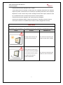
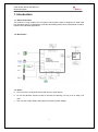
1
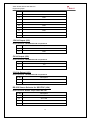
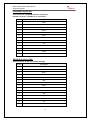
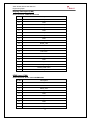
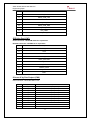
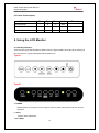
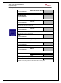
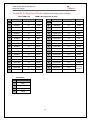
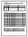
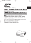
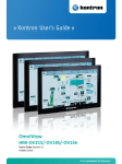
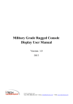
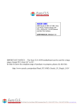
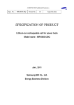
S2AP Scaler Board Powerful graphics processing board, providing high-quality images for TFT panels. S2AP Scaler Board supports V-by-One panels up to 4K2K UHD (3840x2160) and can be used in a variety of systems. User Manual / Engineering Spec. Version 1.0 S2AP Scaler Board User Manual / Engineering Spec. Winmate Communication Inc. Copyright© S2AP User Guide Version: 1.0 REVISION HISTORY REVISION AUTHOR DATE DESCRIPTION 0.1 Michael Lee 11/19/2014 Draft 0.2 Michael Lee 01/15/2015 Adding pin definition 1.0 Eric 01/22/2015 First Release 1 S2AP Scaler Board User Manual / Engineering Spec. IMPORTANT SAFETY INSTRUCTIONS 1. Please read these instructions carefully before using the product and save for later reference. 2. Follow all warnings and instructions marked on the product. 3. Unplug this product from the wall outlet before cleaning. Clean the product with a damp soft cloth. Do not use liquid or aerosol cleaners as it may cause permanent damage to the screen. 4. Do not use this product near water. 5. Do not place this product on an unstable cart, stand, or table. The product may fall, causing serious damage to the product. 6. Slots and openings in the cabinet and the back or bottom are provided for ventilation; to ensure reliable operation of the product and to protect it from overheating, these openings must not be blocked or covered. The openings should never be placed near or over a radiator or heat register, or in a built-in installation unless proper ventilation is provided. 7. This product should be operated from the type of power indicated on the marking label. If you are not sure of the type of power available, consult your dealer or local power company. 8. This product is equipped with a 3-wire grounding type plug, a plug having a third (grounding) pin. This plug will only fit into a grounding-type power outlet. This is a safety feature. If you are unable to insert the plug into the outlet, contact your electrician to replace your obsolete outlet. Do not defeat the purpose of the grounding-type plug. 9. Do not allow anything to rest on the power cord. Do not locate this product where persons will walk on the cord. 10. If an extension cord is used with this product, make sure that the total of the ampere ratings on the products plugged into the extension cord does not exceed the extension cord ampere rating. Also make sure that the total of all products plugged into the wall outlet does not exceed 15 amps. 11. Never push objects of any kind into this product through cabinet slots as they may touch dangerous voltage points or short out parts that could result in a risk of fire or electric shock. Never spill liquid of any kind on the product. 12. Do not attempt to service this product yourself, as opening or removing covers may expose you to dangerous voltage points or other risks and will void the warranty. Refer all servicing to qualified service personnel. 13. Unplug this product from the wall outlet and refer servicing to qualified service personnel under the following conditions: - When the power cord or plug is damaged or frayed. - If liquid has been spilled into the product. 2 S2AP Scaler Board User Manual / Engineering Spec. - If the product has been exposed to rain or water. - If the product does not operate normally when the operating instructions are followed. Adjust only those controls that are covered by the operating instructions since improper adjustment of other controls may result in damage and will often require extensive work by a qualified technician to restore the product to normal operation. - If the product has been dropped or the cabinet has been damaged. - If the product exhibits a distinct change in performance, indicating a need for service. - If the option module is in installation (the module is still not plugged into the slot) CAUTION Read manual prior to installing the product. The operation of products depends on you reading and following the information in this manual. Re-check your work prior to operating the product. EVENT EFFECT PREVENTION Sunlight shines directly will You should avoid placing the cause the panel damage. product under direct sunlight. If the product is close to the wet ground such as grassplot, the moisture between panel and glass will make the product malfunction. 3 You should avoid placing the product in wet environment. S2AP Scaler Board User Manual / Engineering Spec. Contents 1. INTRODUCTION ......................................................................................... 5 1.1. ABOUT THE PRODUCT .................................................................................. 5 1.2. BLOCK CHART ............................................................................................. 5 1.3. NOTICE ....................................................................................................... 5 1.4. CHECK LIST ................................................................................................ 6 2. REMOTE CONTROL .................................................................................. 7 2.1. INSTALL BATTERY IN THE REMOTE CONTROL ................................................. 7 2.2. REMOTE CONTROL KEY DEFINITIONS ............................................................ 7 3. INPUT SIGNALS OVERVIEW .................................................................... 8 3.1. POWER & SIGNAL CONNECTIONS .................................................................. 8 4. CONNECTORS AND PIN ASSIGNMENT .................................................. 9 4.1 A/D BOARD I/O & CONNECTOR ..................................................................... 9 4.2 I/O & CONNECTOR PIN DEFINITION .............................................................. 11 4.3 POWER CONSUMPTION ............................................................................... 20 5. USING THE LCD MONITOR..................................................................... 20 5.1 OSD KEY DEFINITION ................................................................................. 20 5.2 OSD HOT KEYS (AUTO).............................................................................. 21 5.3 OSD MENU NAVIGATION ............................................................................. 22 6. CLEANING THE MONITOR...................................................................... 26 7. DISCLAIMER ............................................................................................ 26 8. TROUBLESHOOTING .............................................................................. 26 APPENDIX B: USING RS-232 COMMAND CODE TO SET SYSTEM (OPTIONAL) ................................................................................................. 29 APPENDIX C : USING RS-232 COMMAND CODE TO CHECK SYSTEM STATUS (OPTIONAL) .................................................................................. 30 4 S2AP Scaler Board User Manual / Engineering Spec. 1. Introduction 1.1. About the Product This product is a high quality TFT LCD panel control Board. S2AP is designed for 4K2K Ultra high resolution panel. It’s designed to meet the demanding performance requirements of today’s business and industrial applications. 1.2. Block Chart 1.3. Notice a. Do not touch the LCD panel surface with sharp or hard objects. b. Do not use abrasive cleaners, waxes or solvents for cleaning, use only a dry or damp, soft cloth. c. Use only with a high quality, safety-approved, AC/DC power adapter. 5 S2AP Scaler Board User Manual / Engineering Spec. 1.4. Check List Before using this monitor, please make sure that all the items listed below are present in your package 1. VGA cable x1 2. AC to DC adapter x1 3. Power cord x1 4. User manual x1 5. 3.5mm Audio cable (optional) x1 6. HDMI cable (optional) x1 7. Display Port cable (optional) x1 8. Remote controller(optional) x1 If any items are missing or damaged, please contact your dealer immediately. 6 S2AP Scaler Board User Manual / Engineering Spec. 2. Remote Control 2.1. Install Battery in the Remote Control Insert two AAA Alkaline batteries and match the (+) and (-) on battery to the marks inside the battery compartment. Service life of battery: 1. The battery normally last for about one year although this depends on how often and for what operations the remote control is used. 2. If the remote control unit fails to work even then it’s operated near the player, please replace the battery. 2.2. Remote Control Key Definitions Key Function / / Description Power Power on/off Auto Auto Adjust Source Switch input source Menu Display OSD menu Volume Adjust volume Exit Return to the previous menu level Reset Factory reset Scaling Change the scaling mode to Fill or aspect Auto-color perform Auto-Color Balance Mute Mute Select Navigating to Up/Down/Left/Right Enter Execute / 7 S2AP Scaler Board User Manual / Engineering Spec. 3. Input Signals Overview The LCD output can be configured to use any of the available input formats (VGA, HDMI, and Display Port). S2AP Monitor Connectors 3.1. Power & Signal Connections 3.1.1. Power: Switch off the power on both your monitor and your computer. The Power Switch is located at the rightmost button of the keypad. 3.1.2. Power cable connection: Connect the power cord to the AC outlet, and connect the power to the monitor through the AC/DC adapter. 3.1.3. VGA cable connection: Plug 15-pin VGA signal cable to the VGA connector in the rear of PC system, and plug the other end to the monitor. Secure cable connectors with screws. 3.1.4. HDMI / Display Port cable connection Plug the HDMI / Display Port signal cable to your PC or other devices, and plug the other end to the monitor. 3.1.5 RS232 cable connection (Optional): You will be able to develop your own application software utilizing the built-in RS232 command code. The application software can send command from PC to LCD monitor via RS232 port to control LCD monitor. Please refer to Appendix B for built-in RS232 command code. 8 S2AP Scaler Board User Manual / Engineering Spec. 4. Connectors and Pin Assignment 4.1 A/D Board I/O & Connector Connector Description J2 3.5mm Stereo Input J3 Reserved FRC JTAG J4 Speaker Output J5 Reserved FRC I2C J7 To Backlight Unit J11 IR Sensor J12 Reserved SoC I2C J13 LPM Console Port J16 Power Din 4 Pin Input J17 Power Wafer Input 9 S2AP Scaler Board User Manual / Engineering Spec. J18 Power Wafer Output J19 12V/1A Output J20 5V/1A Output J21 3.3V/1A Output J24 RS-232 Source Selector for SOC/FRC CN1 VGA Wafer Input CN2 VGA D-Sub Input CN4 Display Port Input CN6 HDMI Input CN7 OSD Key pad CN8 8 Lanes V by one Output CN11 MCU ISP Port CN12 Stereo Line Output JP2 FRC bootstrap JP4 3-Wire RS-232 JP5 24V/12V Selector for Power Input 10 S2AP Scaler Board User Manual / Engineering Spec. 4.2 I/O & Connector Pin Definition 3.5 Ø Stereo Input (J2) Used connector: WTJ-035-36B-01 3.5ψ Pin No. Name 1 GND 2 VGA_R 3 VGA_L 4 NC 5 NC 6 NC Reserved FRC JTAG (J3) Used connector: Pin Header 2*5p P:2.0mm DIP 180° Pin No. Name 1 GND 2 TCK 3 V33_A (+3.3V output) 4 TDO 5 RST_N 6 TMS 7 NC 8 TRST 9 GND 10 TDI Speaker Output (J4) Connector Type: JST-B4B-PH-K-S or equivalent. Pin No. Name 1 LOUT+ 2 LOUT- 3 ROUT- 4 ROUT+ 11 S2AP Scaler Board User Manual / Engineering Spec. Reserved FRC I2C (J5) Connector Type: JST-B4B-PH-K-S or equivalent. Pin No. Name 1 GND 2 SCL 3 SDA 4 NC To Backlight Unit (J7) Used connector: JST-B7B-PH-K-S or equivalent. Pin No. Description 1 +12V 2 +12V 3 +12V 4 GND 5 ADJ 6 GND 7 ON/OFF IR Sensor (J11) Used connector: JST-B3B-PH-K-S or equivalent. Pin No. Description 1 IR 2 GND 3 +5V Reserved SoC IIC (J12) Connector Type: JST-B4B-PH-K-S or equivalent. Pin No. Name 1 +3.3V_LPM 2 LPM_MSTR_SDA 3 LPM_MSTR_SCL 4 GND 12 S2AP Scaler Board User Manual / Engineering Spec. Power Din 4 Pin Input (J16) Used connector: Power Jack Din 4p dip Quick Lock Pin No. Description 1 +12V/+24V 2 Ground 3 +12V/+24V 4 Ground Power Wafer Input (J17) Connector Type: 2.0mm 2 x 6 Pin Header DIP180 degree Pin No. Description 1 +12V/+24V 2 +12V/+24V 3 +12V/+24V 4 +12V/+24V 5 +12V/+24V 6 +12V/+24V 7 GND 8 GND 9 GND 10 GND 11 GND 12 GND Power Wafer Output (J18) Connector Type: JST-B20B-PHDSS or equivalent. Pin No. Description 1 +12V/+24V 2 +12V/+24V 3 +12V/+24V 4 +12V/+24V 5 +12V/+24V 6 +12V/+24V 7 +12V/+24V 8 +12V/+24V 9 +12V/+24V 10 +12V/+24V 13 S2AP Scaler Board User Manual / Engineering Spec. 11 GND 12 GND 13 GND 14 GND 15 GND 16 GND 17 GND 18 GND 19 GND 20 GND 12V/1A Output (J19) Used connector: JST-B2B-PH-K-S or equivalent. Pin No. Description 1 +12V 2 GND 5V/1A Output (J20) Used connector: JST-B2B-PH-K-S or equivalent. Pin No. Description 1 +5V 2 GND 3.3V/1A Output (J21) Used connector: JST-B2B-PH-K-S or equivalent. Pin No. Description 1 +3.3V 2 GND RS-232 Source Selector for SOC/FRC (J24) Used connector: Header 2*2p P:2.0mm DIP 180° Pin No. Description 1,2 SoC RXD 3,4 SoC TXD 5,6 FRC RXD 7,8 FRC TXD 14 S2AP Scaler Board User Manual / Engineering Spec. VGA Wafer Input(CN1) Used connector: JST-B13B-PH-K-S or equivalent. Related connector: JST-PHR-13 or equivalent l Pin No. Description 1 Red+ 2 Red- 3 Green+ 4 Green- 5 Blue+ 6 Blue- 7 SDA 8 HS 9 VS 10 Cable Detect 11 SCL 12 GND 13 VGA 5V VGA D-Sub Input (CN2) Used connector: D-Sub 15p 3.08mm 90°(DIP) Pin No. Description 1 Red+ 2 Green+ 3 Blue+ 4 NC 5 Cable Detect 6 Red- 7 Green- 8 Blue- 9 VGA5V 10 GND 11 NC 12 SDA 13 HS 14 VS 15 SCL 15 S2AP Scaler Board User Manual / Engineering Spec. Display Port Input (CN4) Used connector: 3VD51203-D7JJ-7H Pin No. Description 1 DPRX_L3N 2 GND 3 DPRX_L3P 4 DPRX_L2N 5 GND 6 DPRX_L2P 7 DPRX_L1N 8 GND 9 DPRX_L1P 10 DPRX_L0N 11 GND 12 DPRX_L0P 13 Pull Down 14 Pull Down 15 DPRX_AUXP 16 GND 17 DPRX_AUXN 18 DPRX_HotPlug 19 DPRX_PWR return 20 DPRX_PWR HDMI Input (CN6) Used connector: U7211-19P-110R/SMD+DIP Pin No. Description 1 HDMI_RX2+ 2 GND 3 HDMI_RX2- 4 HDMI_RX1+ 5 GND 6 HDMI_RX1- 7 HDMI_RX0+ 8 GND 9 HDMI_RX0- 10 HDMI_RXC+ 16 S2AP Scaler Board User Manual / Engineering Spec. 11 GND 12 HDMI_RXC- 13 HDMI_CON_CEC 14 NC 15 HDMI_CON_SCL 16 HDMI_CON_SDA 17 HDMI_CON_CABLE 18 +5V_HDMI 19 HDMI_CON_HP OSD Key Pad (CN7) Used connector: JST-B10B-PH-K-S or equivalent. Related connector: JST-PHR-10 or equivalent Pin No. Description 1 GREEN_LED 2 +3.3V 3 NC 4 GPADC_AIN1 5 ADC2_RETURN 6 ADC_VREF 7 ADC1_RETURN 8 GPADC_AIN0 9 LED_AMBER 10 GND 8 Lanes V by One Output (CN8) Used connector: Hirose-DF13DP-1.25V Pin No. 1 2 3 4 5 6 7 8 9 10 11 Symbol PNL_PWR PNL_PWR PNL_PWR PNL_PWR PNL_PWR PNL_PWR PNL_PWR PNL_PWR NC GND GND Description Power output (+12V) Power output (+12V) Power output (+12V) Power output (+12V) Power output (+12V) Power output (+12V) Power output (+12V) Power output (+12V) No Connection Ground Ground 17 S2AP Scaler Board User Manual / Engineering Spec. 12 13 14 15 16 17 18 19 20 21 22 23 24 25 26 27 28 29 30 31 32 33 34 35 36 37 38 39 40 41 42 43 44 45 46 47 48 49 50 51 GND GND GND LRI LR 2D3D SDA SCL NC NC LD_EN NC NC HTPDN LOCKN GND TX0N TX0P GND TX1N TX1P GND TX2N TX2P GND TX3N TX3P GND TX4N TX4P GND TX5N TX5P GND TX6N TX6P GND TX7N TX7P GND Ground Ground Ground Input signal for Glasses Left Right signal Output signal for Left/Right synchronous signal 2D/3D Enable I2C Data signal I2C Clock signal No Connection No Connection Local Dimming Mode Enable No Connection No Connection Hot plug detect input Lock detect input Ground Negative V-by-One differential data output Lane 0 Positive V-by-One differential data output Lane 0 Ground Negative V-by-One differential data output Lane 1 Positive V-by-One differential data output Lane 1 Ground Negative V-by-One differential data output Lane 2 Positive V-by-One differential data output Lane 2 Ground Negative V-by-One differential data output Lane 3 Positive V-by-One differential data output Lane 3 Ground Negative V-by-One differential data output Lane 4 Positive V-by-One differential data output Lane 4 Ground Negative V-by-One differential data output Lane 5 Positive V-by-One differential data output Lane 5 Ground Negative V-by-One differential data output Lane 6 Positive V-by-One differential data output Lane 6 Ground Negative V-by-One differential data output Lane 7 Positive V-by-One differential data output Lane 7 Ground 8051 ISP Port (CN11) Used connector: Wafer 5p P:1.25mm SMD 180° white Pin No. Description 1 +3.3V 18 S2AP Scaler Board User Manual / Engineering Spec. 2 C2D 3 C2CK 4 #RESET 5 GND Stereo Line Output (CN12) Used connector: Wafer 6p P:1.0mm SMD 180° white Pin No. Description 1 LINEOUT_DET 2 AUD_R1_OUT 3 RINP 4 LINP 5 AUD_L1_OUT 6 GND FRC Bootstrap(JP2) Used connector: Header 1*3p P:2.0mm DIP 180° Pin No. Description 1-2 Pull up to 3.3V 2-3 Pull down to GND 3-Wire RS-232 (JP4) Connector Type: 2*5p P:2.54mm DIP 90° L10*H6m Pin No. Description Pin No. Description 1 2 3 4 5 NC NC RS-232 TX NC RS-232 RX 6 7 8 9 10 NC NC NC GND NC 24V/12V Selector for Power Input (JP5) Used connector: Header 2*2p P:2.54mm DIP 180° Pin No. Description 1-2 12V 3-4 24V 19 S2AP Scaler Board User Manual / Engineering Spec. 4.3 Power Consumption Parameter Min. Typ. Max. Unit. Operating Mode - 8 12 Watt Standby Mode - 2.5 - Watt Off Mode - - 0.2 Watt Remark 5. Using the LCD Monitor 5.1 OSD Key Definition There are two types OSD keypad for S2AP board, the type of OSD is according to the housing of the LCD monitor. Type B is standard OSD keypad for kit. Type A. Type B a. POWER Initiates power-up sequence from low power mode or enters low power mode from normal operation. b. AUTO Perform Auto Adjustment c. Esc (EXIT) 20 S2AP Scaler Board User Manual / Engineering Spec. i. When OSD is enabled, it returns to the previous menu level or closes the OSD. d. OK/MENU (ENTER) i. When OSD is disabled, it displays the OSD Main Menu. ii. When OSD is enabled, it confirms a selection. e. LEFT Moves left in the menu or bar f. RIGHT Moves right in the menu or bar g. UP i. Selects the previous item in the Menu. h. DOWN i. Selects the next item in the Menu. 5.2 OSD Hot Keys (Auto) Function Hot Key Main source Press “ ” to select the main source Volume Press “ ” to the volume bar, and press “ ” “ ” to adjust the volume Auto adjustment Press “AUTO” to perform auto adjustment 21 S2AP Scaler Board User Manual / Engineering Spec. 5.3 OSD Menu Navigation OSD menu navigation 5.3.1 Display OSD icon Sub menu BRIGHTNESS Settings slider bar Adjusts the overall image and background brightness. Press “ CONTRAST Note ” or “ ” to adjust. slider bar Adjusts the image brightness in relationship to the background. Press“ SHARPNESS ” or “ ” to adjust. slider bar Adjusts the crispness of the image. Press“ ” or “ ” to adjust. ADC BRIGHTNESS slider bar *VGA CHANNEL ONLY Adjusts the ADC brightness. Press“ COLOR TEMPERATURE ” or “ ” to adjust. USER/6500K/9300K Adjusts the color temperature of the entire screen. A low color temperature will make the screen 22 S2AP Scaler Board User Manual / Engineering Spec. reddish. A high color temperature will make the screen bluish. R slider bar G slider bar B slider bar COLOR CONTROL Adjusts the levels of the Red, Green, Blue, Yellow, magenta, and cyan. Press“ adjust. @NATIVE GAMMA SELECTION @1.8 @2.2 Select a display gamma value for best picture quality. DISPLAY RESET YES/NO Resets the following settings within the DISPLAY menu back to factory setting: 23 ” or “ ” to S2AP Scaler Board User Manual / Engineering Spec. 5.3.2 Adjust AUTO SETUP PRESS YES TO AUTO SETUP *VGA CHANNEL ONLY Automatically adjusts screen size, H position, V position, Clock, Clock Phase AUTO ADJUSTMENT ON/OFF *VGA CHANNEL ONLY H Position, V Position and Clock Phase are adjusted automatically upon power On. H POSITION slider bar *VGA CHANNEL ONLY Controls the horizontal position of the image within the Display area of the LCD. Press + to move right. Press - to move left. V POSITION slider bar *VGA CHANNEL ONLY Controls the vertical position of the image within the Display area of the LCD. Press + to move up. Press - to move down. CLOCK slider bar *VGA CHANNEL ONLY Press + to expand the width of the image on the right of the screen. Press - to narrow the width of the image on the left. PHASE slider bar *VGA CHANNEL ONLY Adjusts the visual “noise” on the image. WHITE BALANCE YES/OFF *VGA CHANNEL ONLY Perform the white balance @ ASPECT SCALING @ FULL Adjust the image scaling setting ADJUST RESET YES/NO Resets the following settings within the ADJUST menu back to factory setting: 24 S2AP Scaler Board User Manual / Engineering Spec. 5.3.3 Audio VOLUME Slider bar MUTE ON/OFF AUDIO RESET YES/NO Resets “AUDIO” settings back to factory settings. 5.3.4 OSD settings OSD TURN OFF slider bar Turns off the OSD after a period of inactivity. The preset options are 0-60 seconds. @OFF OSD TRANSPARENCY @TYPE1 @TYPE2 Set the transparency level of OSD Version MONITOR INFORMATION Panel Resolution Main Resolution Show BIOS version & resolution info. OSD RESET YES/NO Resets the following settings within the OSD menu back to factory setting 5.3.6 Advanced settings VGA CHANNEL SELECT HDMI DP Select the input signal source BRIGHTNESS MIN Slide bar ADVANCED RESET YES/NO Resets the following settings within the ADVANCED menu back to factory setting FACTORY RESET YES/NO Resets OSD options back to factory settings EXCEPT FOR: CHANGE SECURITY PASSWORD and SECURITY PASSWORD. 25 S2AP Scaler Board User Manual / Engineering Spec. 6. Cleaning the Monitor 1. Make sure the monitor is turned off. 2. Never spray or pour any liquid directly on the screen or case. 3. Wipe the screen with a clean, soft, lint-free cloth. This removes dust and other particles. 4. The display area is highly prone to scratching. Do not use ketone type material (ex. Acetone), Ethyl alcohol, toluene, ethyl acid or Methyl chloride to clear the panel. It may permanently damage the panel and void the warranty. 5. If it is still not clean enough, apply a small amount of non-ammonia, non-alcohol based glass cleaner onto a clean, soft, lint-free cloth, and then wipe the screen. 6. Don’t use water or oil directly on the monitor. If droplets are allowed to drop on the monitor permanent staining or discoloration may occur. 7. Disclaimer We do not recommend using any ammonia or alcohol-based cleaners on the monitor screen or case. Some chemical cleaners or solvents have been reported to damage the screen and/or case of the monitor. Seller will not be liable for damage resulting from the use of any ammonia or alcohol-based cleaner. 8. Troubleshooting If your monitor fails to operate correctly, consult the following chart for possible solution before calling for repairs: Condition 1. The picture does not appear Check Point Check if the signal cable is firmly seated in the socket. Check if the Power is ON at the computer Check if the brightness control is at the appropriate position, not at the minimum. 2. The screen is not synchronized Check if the signal cable is installed firmly. Check if the output level matches the input level of your computer. Make sure the signal timings of the computer system are within the specification of the monitor. 26 S2AP Scaler Board User Manual / Engineering Spec. If your computer was working with a CRT monitor, you should check the current signal timing and turn off your computer before you connect the VGA Cable to this monitor. 3. The position of the screen is not in the center 4. The screen is too bright adjustment. or too dark Check if the brightness or contrast control is at the appropriate position, not at the Maximum (Minimum). Perform the Auto adjustment. Moving all objects which emit a magnetic field such as motor or transformer, away from the monitor. 5. The screen is shaking or waving Adjust the H-position, and V-position, or Perform the Auto Check if the specific voltage is applied. Check if the signal timing of the computer system is within the specification of monitor. If you are unable to correct the fault by using this chart, stop using your monitor and contact your distributor or dealer for further assistance. 27 S2AP Scaler Board User Manual / Engineering Spec. Appendix A: Supported Modes (Depend on the monitor native resolution) VGA / HDMI / DP (HDMI / DP support 60 Hz Only) No. Resolution Frequency (Hz) Note No. Resolution Frequency (Hz) Note 1 640x350 70 IBM 20 1280x768 60 VESA 2 640x350 85 VESA 21 1280x800 60 VESA 3 640x400 56 - 22 1280x960 85 VESA 4 640x400 70 IBM 23 1280x1024 60 VESA 5 640x480 75 VESA 24 1280x1024 67 IBM 6 640x480 80 VESA 25 1280x1024 70 NCD 7 720x350 70 IBM 26 1280x1024 72 HP 8 720x400 70 IBM 27 1280x1024 75 VESA 9 720x400 85 VESA 28 1280x1024 85 VESA 10 800x600 56 VESA 29 1360x768 60 VESA 11 800x600 60 VESA 30 1366x768 60 VESA 12 800x600 72 VESA 31 1440x900 60 VESA 13 800x600 75 VESA 32 1600x1200 60 VESA 14 800x600 85 VESA 33 1680x1050 60 VESA 15 1024x768 60 VESA 34 1920x1200 60 CVT RB 16 1024x768 70 VESA 35 1920x1080 60 VESA 17 1024x768 72 IBM 36 2560x1440 60 18 1024x768 75 VESA 37 2560x1600 60 19 1024x768 85 VESA 38 3840x2160 30 Video Mode No. Resolution 1 480P 2 576P 3 720P 4 1080P 28 No VGA Support S2AP Scaler Board User Manual / Engineering Spec. Appendix B: Using RS-232 Command Code to set system (Optional) Name Message Length Value Comment variable byte chksum = 0; Checksum 1 2's complement of sum of Length and for ( i = 0; i < buffer_size; ++i ) Message chksum += buf[i]; chksum = ~chksum + 1; RS232 setting: Baud Rate = 115200, Data Bits=8, Parity = None, Stop Bits=1 Function Length Command ID index Value Auto 0x05 0x40 0x01 Recall 0x05 0x40 0x02 WhiteBalance 0x05 0x40 0x03 0x05 0x40 0x04 0=VGA,7=HDMI, 8=DP Brightness 0x05 0x40 0x10 0x00-0x64 Contrast 0x05 0x40 0x11 0x00-0x64 Scaling 0x05 0x40 0x22 1=COSTOM, 2=Aspect Gamma 0x05 0x40 0x31 0=Off,1=1.8,2=2.2 Color Temp 0x05 0x40 0x32 0=user,1=6500K,2=9300K Color-R 0x05 0x40 0x33 0x00-0xFF Color-G 0x05 0x40 0x34 0x00-0xFF Color-B 0x05 0x40 0x35 0x00-0xFF Volume 0x05 0x40 0x50 0x00-0x1F Mute 0x05 0x40 0x54 0=Mute On,1=Mute OFF Main Input Source Reply Value: ACK 3 C F1 Transmission PASS NSP 3 D F0 Transmission FAILED NCK 3 B F2 Not support Format: Length, Command, ID, index, Value, Checksum Example:0x06, 0x40, ID, 0x00, 0x01, Checksum => Power Off system. 29 checksum S2AP Scaler Board User Manual / Engineering Spec. Appendix C : Using RS-232 Command Code to check system status (optional) Name Length Value Message variable Comment byte chksum = 0; Checksum 1 2’s complement of sum of Length and Message for ( I = 0; I < buffer_size; ++I ) chksum += buf[i]; chksum = ~chksum + 1; Command(Tx) function Main Input Acknowledgement(Rx) Length Command ID index checksum Length ID index Value 0x04 0x30 0x04 0x04 0x04 0=VGA, 7=HDMI, 8=DP Brightness 0x04 0x30 0x10 0x04 0x10 0x00-0x64 Contrast 0x04 0x30 0x11 0x04 0x11 0x00-0x64 Scaling 0x04 0x30 0x22 0x04 0x22 1=FILL,2=Aspect Gamma 0x04 0x30 0x31 0x04 0x31 0=Off,1=1.8,2=2.2 Color Temp 0x04 0x30 0x32 0x04 0x32 0=user,1=6500K,2=9300K Color-R 0x04 0x30 0x33 0x04 0x33 0x00-0xFF Color-G 0x04 0x30 0x34 0x04 0x34 0x00-0xFF Color-B 0x04 0x30 0x35 0x04 0x35 0x00-0xFF Volume 0x04 0x30 0x50 0x04 0x50 0x00-0x1F Mute 0x04 0x30 0x54 0x04 0x54 0=Mute On,1=Mute OFF Source Reply Value: ACK 3 C F1 Transmission PASS NSP 3 D F0 Transmission FAILED NCK 3 B F2 Not support Format: Length, Command, ID, index, Checksum / Length, ID, Index, Value, Checksum 30 checksum