1
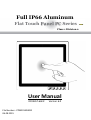
Full IP66 Aluminum Flat Touch Panel PC Series Class 1 Division 2 User Manual R19IHAT-66EX File Number : PPM201404282 06.08.2015 Version 6.0 19” Full IP66 Flat Touch PPC User’s Manual Copyright Notice No part of this document may be reproduced, copied, translated, or transmitted in any form or by any means, electronic or mechanical, for any purpose, without the prior written permission of the original manufacturer. Trademark Acknowledgement Brand and product names are trademarks or registered trademarks of their respective owners. Disclaimer We reserves the right to make changes, without notice, to any product, including circuits and/or software described or contained in this manual in order to improve design and/or performance. We assume no responsibility or liability for the use of the described product(s), conveys no license or title under any patent, copyright, or masks work rights to these products, and makes no representations or warranties that these products are free from patent, copyright, or mask work right infringement, unless otherwise specified. Applications that are described in this manual are for illustration purposes only. We make no representation or warranty that such application will be suitable for the specified use without further testing or modification. 2 19” Full IP66 Flat Touch PPC User’s Manual Warranty Our warranty that each of its products will be free from material and workmanship defects for a period of one year from the invoice date. If the customer discovers a defect, we will, at its option, repair or replace the defective product at no charge to the customer, provided it is returned during the warranty period of one year, with transportation charges prepaid. The returned product must be properly packaged in the original packaging to obtain warranty service. If the serial number and the product shipping data differ by over 30 days, the in-warranty service will be made according to the shipping date. In the serial numbers the third and fourth two digits give the year of manufacture, and the fifth digit means the month (e. g., with A for October, B for November and C for December). For example, the serial number 1W08Axxxxxxxx means October of year 2008. Customer Service We provide service guide for any problem as follow steps: First, visit the website of our distributor to find the update information about the product. Second, contact with your distributor, sales representative, or our customer service center for technical support if you need additional assistance. You may have the following information ready before you call: • Product serial number • Peripheral attachments • Software (OS, version, application software, etc.) • Description of complete problem • The exact wording of any error messages In addition, free technical support is available from our engineers every business day. We are always ready to give advice on application requirements or specific information on the installation and operation of any of our products. Please do not hesitate to call or e-mail us. 3 19” Full IP66 Flat Touch PPC User’s Manual Safety Information WARNING! Always completely disconnect the power cord from your chassis whenever you work with the hardware. Do not make connections while the power is on. Sensitive electronic components can be damaged by sudden power surges. Only experienced electronics personnel should open the PC chassis. CAUTION! Always ground yourself to remove any static charge before touching the CPU card. Modern electronic devices are very sensitive to static electric charges. As a safety precaution, use a grounding wrist strap at all times. Place all electronic components in a static-dissipative surface or static-shielded bag when they are not in the chassis. Safety Precautions • Please read these safety instructions carefully. • Please keep this user’s manual for later reference. • Please disconnect this equipment from any AC outlet before cleaning. Do not use liquid or spray detergents for cleaning. Use a damp cloth. • Do not touch the LCD panel surface with sharp or hard objects. • For pluggable equipment, the power outlet must be installed near the equipment and must be easily accessible. • Keep this equipment away from humidity. • Place this equipment on a reliable surface during installation. Dropping it or letting it fall could cause damage. • The openings on the enclosure are for air convection. Protect the equipment from overheating. DO NOT COVER THE OPENINGS. • Make sure the voltage of the power source is correct before connecting the equipment to the power outlet. • Position the power cord so that people cannot step on it. Do not place anything over the power cord. • All cautions and warnings on the equipment should be noted. • If the equipment is not used for a long time, disconnect it from the power source to avoid damage by transient over-voltage. • Never pour any liquid into an opening. This could cause fire or electrical shock. • Never open the equipment. For safety reasons, only qualified service personnel should open the equipment. • This equipment is designed to be used in restricted access location. Only service persons or trained persons are allowed to access this equipment. 4 19” Full IP66 Flat Touch PPC User’s Manual • If any of the following situations arises, get the equipment checked by service personnel: The power cord or plug is damaged. Liquid has penetrated into the equipment. The equipment has been exposed to moisture. The equipment does not work well, or you cannot get it to work according to the user’s manual. The equipment has been dropped and damaged. The equipment has obvious signs of breakage. • Do not leave this equipment in an uncontrolled environment where the storage temperature is below -20°C (-4°F) or above 70°C (158°F). It may damage the equipment. • Ne laissez pas ce matériel dans un environnement non contrôlé où la température de stockage est inférieure à -20 ° C ( -4 ° F ) ou au-dessus de 70 ° C ( 158 ° F ) . Il peut endommager le matériel. • CAUTION – Use recommended mounting apparatus to avoid risk of injury. • ATTENTION - Utilisez recommandé appareil de montage pour éviter les risques de blessure. • WARNING – Only use the connection cords which comes along with the product, when in doubt, please contact the manufacturer. • ATTENTION - Utilisez uniquement les cordons de connexion qui vient avec le produit , en cas de doute , s'il vous plaît contactez le fabricant. • Provision shall be made to provide transient protection device to be set at a level not exceeding 140% of the rated voltage at the power supply terminals of the apparatus. • Des dispositions seront prises pour fournir dispositif de protection contre les transitoires à être fixé à un niveau ne dépassant pas 140 % de la tension nominale aux bornes d'alimentation de l'appareil. • WARNING – Explosion Hazard – Do not disconnect equipment unless power has been switched off or the area is known to be non-hazardous. • AVERTISSEMENT - Risque d'explosion - Ne débranchez pas l'équipement que l'alimentation est coupée ou que la zone est connue pour être non dangereux • WARNING – Explosion Hazard – Do not apply any audio connectors in Hazardous Location. • AVERTISSEMENT - Risque d'explosion - Ne pas appliquer tous les connecteurs audio dans des environnements dangereux . • WARNING – The equipment should be adequately protected from direct light when installed indoor or outdoor. • AVERTISSEMENT - L'équipement doit être adéquatement protégé de la lumière directe lors de l'installation intérieure ou extérieure. • WARNING – DO NOT OPEN, MAINTAIN OR SERVICE IN AN AREA WHERE AN EXPLOSIVE ATMOSPHERE MAY BE PRESENT. • AVERTISSEMENT - NE PAS OUVRIR , maintenir ou SERVICE DANS UN ENDROIT OÙ UNE ATMOSPHERE EXPLOSIVE PEUT ETRE PRESENTE . • THIS EQUIPMENT IS SUITABLE FOR USE IN CLASS I, DIVISION 2, GROUPS A, B, C, D OR NON-HAZARDOUS LOCATIONS ONLY. • Cet équipement est utilisable en Classe I, Division 2, Groupes A, B , C , D LIEUX OU non dangereux. • WARNING - EXPLOSION HAZARD – SUBSTITUTION OF COMPONENTS MAY IMPAIR SUITABILITY FOR CLASS I, DIVISION 2; 5 19” Full IP66 Flat Touch PPC User’s Manual • AVERTISSEMENT - RISQUE D'EXPLOSION - substitution de composants peut nuire à la conformité Classe I, Division 2 ; • WARNING - EXPLOSION HAZARD - DO NOT REPLACE PARTS UNLESS POWER HAS BEEN SWITCHED OFF OR THE AREA IS KNOWN TO BE NON-HAZARDOUS; • AVERTISSEMENT - RISQUE D'EXPLOSION - NE PAS remplacer les pièces que l'alimentation est coupée ou que la zone est connue pour être non dangereux; • WARNING - EXPLOSION HAZARD - DO NOT DISCONNECT EQUIPMENT UNLESS POWER HAS BEEN SWITCHED OFF OR THE AREA IS KNOWN TO BE NON-HAZARDOUS; • AVERTISSEMENT - RISQUE D'EXPLOSION - NE PAS déconnecter l'équipement que l'alimentation est Coupée ou la région est connue pour être non dangereux; • WARNING - Do not use USB Port while the hazardous atmosphere is present. • AVERTISSEMENT - Ne pas utiliser le port USB tandis que l'atmosphère dangereuse est présente. 6 19” Full IP66 Flat Touch PPC User’s Manual Contents Contents ........................................................................................................................ 7 Introduction .................................................................................................................. 8 Features .......................................................................................................................................... 8 Package Contents............................................................................................................................. 9 Product Overview (Unit: mm) ........................................................................................................ 10 Getting Started ............................................................................................................ 11 Turning On Your Device.................................................................................................................. 11 Adjusting the LCD Display Brightness .............................................................................................. 12 Calibrating Touch Screen ............................................................................................................... 13 Turning Off Your Device ................................................................................................................. 14 Installation .................................................................................................................. 15 Wiring Requirements ..................................................................................................................... 15 Connecting the Interface ............................................................................................................... 16 Wiring ........................................................................................................................................... 16 Mounting Solution ......................................................................................................................... 21 Windows 7 Driver Installation ..................................................................................... 23 Chipset Driver Installation ............................................................................................................. 23 Graphic Driver Installation ............................................................................................................. 25 USB 3.0 Driver Installation ............................................................................................................. 27 Ethernet Driver Installation ........................................................................................................... 30 Audio Driver Installation ................................................................................................................ 31 Fintek COM Port Driver Installation ............................................................................................... 32 Intel Management Engine Software Installation ............................................................................ 35 Specification ................................................................................................................ 37 Hardware Specifications ................................................................................................................ 37 Appendix ..................................................................................................................... 39 Appendix A: Cleaning the Monitor.................................................................................................. 39 Appendix B: Statement of Regulatory Approval .............................................................................. 40 7 19” Full IP66 Flat Touch PPC User’s Manual Introduction Class1 Division2 certification for equipment was created to ensure employee safety in explosive atmospheres. Today many countries have made it a requirement for organizations operating in certain industries to use equipment that meets the regulatory compliance. This includes technologies used in potentially explosive atmospheres. The Winmate 19” HazLoc PPC is the first of its kind to offer the Class1 Division2 certification, ensuring safe and reliable data collection and processing in Hazardous Locations. This Panel PC features robust processing power with the 2.6GHz Intel Haswell Core i5-4300U. The panel PC also offers brilliant visibility with its true flat design, transflective sunlight-viewable, resistive touchscreen with 1280 x 1024 pixel resolution, all in a compact form factor Features • Intel Haswell Core i5-4300U turbo max 2.6 GHz • 19” SXGA High brightness panel, 800 nits • Sunlight readable, transflective, resistive touch LCD Panel • Fanless, streamlined enclosure for highly efficient heat dissipation • Front side buttons, one dedicated button to enable/disable touch screen interface • Built in to withstand extreme temperatures -40 to 70 deg C with built in intelligent heater and wide range temperature memory parts • 9-36 V DC input with isolation (There is no tolerance for the DC input voltage) • Operable in 5-95% humidity level 8 19” Full IP66 Flat Touch PPC User’s Manual Package Contents Before using this Panel PC, please make sure that all the items listed below are present in your package: Panel PC 24V 50W AC to DC adapter for test only Operating System Recovery Manual & Driver CD DVD (Optional) Power Cord 9 Power Connector User Manual 19” Full IP66 Flat Touch PPC User’s Manual Product Overview (Unit: mm) Front View Touch Display Front Button & LED Indicators Side and Rear Views Front Button Button Type Function Power on/off Increase the brightness of the Panel Decrease the brightness of the Panel Suspend the touch’s function temporarily Programmable function key configured by Hot Tab Utility 1 0 19” Full IP66 Flat Touch PPC User’s Manual Getting Started Turning On Your Device 1. Remove the I/O protection cover plate. 2. Connect the Power adapter to the device. 3. Plug the power adapter power cord to an electrical outlet. 4. Touch the Power button on the front to turn on the device. Note • When the system hangs, press the Reset button to restart the device. 1 1 19” Full IP66 Flat Touch PPC User’s Manual Adjusting the LCD Display Brightness 1. Tap the arrow on the system tray to display the hidden icons. 2. Double-tap the icon to display the brightness menu. 3. Drag the brightness bar to adjust the brightness level according to your preference. 10 19” Full IP66 Flat Touch PPC User’s Manual Calibrating Touch Screen When turning on the Panel PC for the first time, it is highly recommended to calibrate the touch screen to ensure touch accuracy. Five-wire resistive touchscreens The five-wire resistive touchscreens use a glass panel with a uniform resistive coating. A thick polyester coversheet is tightly suspended over the top of the glass, separated by small, transparent insulating dots. The coversheet has a hard, durable coating on the outer side and a conductive coating on the inner side. A B A B C C D D E E F F When the screen is touched, the conductive coating makes electrical contact with the coating on the glass. The voltages produced are the analog representation of the position touched. The controller digitizes these voltages and transmits them to the computer for processing. The five-wire technology utilizes the bottom substrate for both X and Y-axis measurements. The flexible coversheet acts only as a voltage-measuring probe. This means the touchscreen will continue working properly even with non-uniformity in the cover sheet’s conductive coating. The result is an accurate, durable and reliable touchscreen that offers drift free operation. The touchscreens are sealed against contamination and moisture. The coversheet is sealed to the glass substrate with an industrial grade caulk. This prevents wicking of fluid between the coversheet and glass. Also, the touchscreens are not air vented, thereby preventing fluid ingress through an air vent. Brief Specifications Subject Details Input Method Finger, gloved hand, or stylus activation Positional Accuracy Standard deviation error is less than 0.080 (2 mm) Resolution Touch point density is based on controller resolution of 4096 x 4096 Touch Activation Force Typically less than 4 ounces (113 grams) Light Transmission HL products: 80% +/–5% at 550 nm wavelength Enhanced products: 60% +/–5% at 550 nm wavelength Update touch-screen driver or new information. Go to www.elotouch.com. 11 19” Full IP66 Flat Touch PPC User’s Manual Elo Touch Correction Winmate ELO Touch driver software provides a consistent software interface among all ELO touch screens and controllers. Go to http://www.elotouch.com/Support/dnld.asp for a complete list of available supports. After the driver installation is complete, do the following to perform touch screen calibration. 1. Tap the arrow on the system tray to display the hidden icons. 2. Double-tap the 3. Double-tap the icon to display the Elo Touchscreen menu. icon to proceed to next step. 12 19” Full IP66 Flat Touch PPC User’s Manual 4. Follow the on-screen instructions to calibrate the touch screen. 5. Tap the icon if the cursor follows your finger to finish and exit the calibration utility. 13 19” Full IP66 Flat Touch PPC User’s Manual Turning Off Your Device To shut down your device, do the following: Tap Start ( ) > Shut down. Wait for your Panel PC to completely turn off before disconnecting the power cord (if necessary). 14 19” Full IP66 Flat Touch PPC User’s Manual Installation Wiring Requirements The following common safety precautions should be observed before installing any electronic device: • Strive to use separate, non-intersecting paths to route power and networking wires. If power wiring and device wiring paths must cross make sure the wires are perpendicular at the intersection point. • Keep the wires separated according to interface. The rule of thumb is that wiring that shares similar electrical characteristics may be bundled together. • Do not bundle input wiring with output wiring. Keep them separate. • When necessary, it is strongly advised that you label wiring to all devices in the system. ATTENTION • Do not run signal or communication wiring and power wiring in the same conduit. To avoid interference, wires with different signal characteristics (i.e., different interfaces) should be routed separately. • Be sure to disconnect the power cord before installing and/or wiring your device. • Verify the maximum possible current for each wire gauge, especially for the power cords. Observe all electrical codes dictating the maximum current allowable for each wire gauge. • If the current goes above the maximum ratings (80 W), the wiring could overheat, causing serious damage to your equipment. • Be careful when handling the unit. When the unit is plugged in, the internal components generate a lot of heat which may leave the outer casing too hot to touch. 15 19” Full IP66 Flat Touch PPC User’s Manual Connecting the Interface The unit is available with different pass through glands for cable connections (required to maintain enclosure protection rating). These glands are water and gas tight and must be tightened with a torque described in the gland manufacturer’s instructions provided with the unit. Cables must be passed through the glands and wired to the associated I/O connectors. MBA12-08-L13-Ex Gland Cable range 5.4~8mm MBA16-10-Ex Gland Cable Range 7.5~10.2mm Wiring 1. Release the screws to remove the I/O protection cover and twisting the cable gland to increase gland opening for later cable go through Twisting the cable gland to increase gland opening to let the cable go through 16 19” Full IP66 Flat Touch PPC User’s Manual 2. I/O cover has been removed and internal I/O ports will be seen. 3. Loosen the cable gland and let the cable go through to connect the internal terminal block connector. Connect to the terminal block Cable goes through the cable gland 17 19” Full IP66 Flat Touch PPC User’s Manual 4. Tighten the cable gland and screw the I/O protection cover plate back. Put all the screws back to fix the I/O Cover Tighten the gland to hold the cable Pin Assignments The pin assignments of the connectors are as follows: VGA Port (Only used in safe area) Pin Signal Name Pin Signal Name 1 R_FILTER 2 G_FILTER 3 B_FILTER 4 NC 5 GND 6 GND 7 GND 8 GND 9 VGA5V 10 GND 11 NC 12 DAC_SDAT0 13 3VHSYNC0 14 3VVSYNC0 15 DAC_SCL0 18 19” Full IP66 Flat Touch PPC User’s Manual COM Port (Only used in safe area) Pin Signal Name Pin Signal Name 1 DCD 2 RXD 3 TXD 4 DTR 5 GND 6 DSR 7 RTS 8 CTS 9 RI Pin Signal Name 1 VCC 2 D- 3 D+ 4 GND Pin Signal Name Pin Signal Name 1 MDI0_IN+ 2 MDI0_IN- 3 MDI1_IN+ 4 MDI2_IN+ 5 MDI2_IN- 6 MDI1_IN- 7 MDI3_IN+ 8 MDI3_IN- Pin Signal Name 1 VCC+ 2 VCC- 3 GND USB Port (Only used in safe area) LAN1 Port (Only used in safe area) Power terminal block *Power wire for VCC should be AMW 1015 18AWG 600V or above. * The wire for GND: Equipotential bonding connection facilities on the outside of electrical equipment shall provide effective connection of a conductor with a cross-sectional area of at least 4 mm². AMW 1015 10AWG 600V is recommend. Please refer to following drawing for grounding screw holes position 19 19” Full IP66 Flat Touch PPC User’s Manual COM Port LAN2 Port Pin Signal Name Pin Signal Name 1 DCD 2 RXD 3 TXD 4 DTR 5 GND 6 DSR 7 RTS 8 CTS 9 RI 10 +V5 Pin Signal Name Pin Signal Name 1 MDIO3- 2 MDIO3+ 3 MDIO2- 4 MDIO2+ 5 MDIO1- 6 MDIO1+ 7 MDIO0- 8 MDIO0+ Pin Signal Name 1 VCC 2 D- 3 D+ 4 GND USB Port Note • This adapter was certified by UL, CUL TUV/GS CE, FCC, BSMI, EK, DOIR+C- TICK, CCC, PSE. 20 19” Full IP66 Flat Touch PPC User’s Manual WARNING Ensure that the external power source is OFF before connecting or disconnecting the DC IN jack. Mounting Solution Clamp Mount With the mounting clamps and screws, it provides fast and easy mounting of the 19” Panel PC onto an instrument panel or wall panel To mount the device to a sub frame or panel, do the following: 1. Prepare a customized fixture for the specific dimension of the display unit 2. Turn off the device and disconnect the power source and other peripherals 3. Cut a hole on the sub frame or panel according to the cut-out dimensions 4. Install the device properly onto the cut-out area of the sub frame or panel 5. Hook the mounting clamp into the corresponding mounting pair slots of the display. Then fasten the clamp with the included mounting screw to secure its position on the sub frame or panel. Repeat the same procedure for the remaining mounting clamps 21 19” Full IP66 Flat Touch PPC User’s Manual VESA Mount Dimensions: 100 x 100mm Screw Hole Diameter: M4 x 5 mm Direction: Compatible with swimming arms mounting kits. 22 19” Full IP66 Flat Touch PPC User’s Manual Windows 7 Driver Installation Chipset Driver Installation The Intel Chipset Drivers should be installed first before the software drivers to enable Plug & Play INF support for Intel chipset components. Follow the instructions below to complete the installation. Step 1. Insert the DVD that comes with the motherboard. Open the file document “Chipset Driver” and click on “Setup.exe“ to install driver. Step 2. Click on “Next“ to install driver. 23 19” Full IP66 Flat Touch PPC User’s Manual Step 3. Click on “Next“ to install driver. Step 4. Click on “Yes, I want to restart this computer now“ to go on. 24 19” Full IP66 Flat Touch PPC User’s Manual Graphic Driver Installation IH70 Motherboard is with Intel mobile Core i7, Core i5, Core i3 dual core CPU and with an integrated graphics controller. You need to install the Graphic driver to enable the function. Intel Graphic supports versatile display options and 32-bit 3D graphics engine. Triple independent display, enhanced display modes for widescreen flat panels for extend, twin, and clone display mode. Step 1. Insert the driver DVD into your system's DVD-ROM drive. You can see the driver folders items. Navigate to the “Graphic Driver“ folder and click "setup.exe" to complete the installation. Step 2. Click on “Next “ to install Driver. Step.3. Click on “Yes “ to agree License. 25 19” Full IP66 Flat Touch PPC User’s Manual Step.4. Click on “Next “ to install Driver. Step.5. Click on “Yes, I want to restart this computer now“ to go on. 26 19” Full IP66 Flat Touch PPC User’s Manual USB 3.0 Driver Installation IH70 Motherboard is designed with Intel mobile Core i7, Core i5, Core i3 dual core CPU with the Intel® USB 3.0 eXtensible Host Controller. You need to install the Intel® USB 3.0 eXtensible Host Controller driver to enable the function. Step.1. Locate the hard drive directory where the driver files are stored with the browser or the explore feature of Windows*. Step.2.Double click the “Setup.exe” from this directory. Step.3. Click “Next” to continue. 27 19” Full IP66 Flat Touch PPC User’s Manual Step.4. Read License Agreement and click “Yes” to proceed Step.5. Review Readme File Information and click “Next” to proceed. Step.6. When the “Setup Progress” is complete click “Next” to proceed. 28 19” Full IP66 Flat Touch PPC User’s Manual Step.7.When the “Setup Progress” is complete click “Next” to proceed. Step.8. Lastly, the “Setup Complete” screen appears so click “Finish” to restart your computer. 29 19” Full IP66 Flat Touch PPC User’s Manual Ethernet Driver Installation The Users must make sure which operating system you are using in the IH70 Motherboard before installing the Ethernet drivers. Follow the steps below to complete the installation of the Intel® I210IT Gigabit-LAN Controller + I218LM Gigabit-LAN drivers. You will quickly complete the installation. Step.1. Insert the driver DVD and select the “LAN Driver” folder. Step.2.Extract the “PROWinX64_19.0 ” file and click on next to install the driver. Step.3 Click on “Next “ to agree License. 30 19” Full IP66 Flat Touch PPC User’s Manual Step.4. Click on “Next“ to install driver. Step.5. Click on “Finish“ to complete the driver installation. Audio Driver Installation The ALC886 series are high-performance 7.1+2 Channel High Definition Audio Codecs providing ten DAC channels that simultaneously support 7.1 sound playback, plus 2 channels of independent stereo sound output (multiple streaming) through the front panel stereo outputs. The series integrates two stereo ADCs that can support a stereo microphone, and feature Acoustic Echo Cancellation (AEC), Beam Forming (BF), and Noise Suppression (NS) technology. The users must make sure which operating system you are using in the IH70 Motherboard before installing the Audio drivers. Follow the steps below to complete the installation of the Realtek ALC886 Audio drivers. You will quickly complete the installation. Step.1. Insert the DVD that comes with the motherboard. Open the folder “Audio Driver” and click on “Audio(64bit_Vista_Win7_Win8_R271 to execute the setup. 31 19” Full IP66 Flat Touch PPC User’s Manual Step.2. Click on “Next“ to install driver. Step.3. Click on “Yes, I want to restart my computer now” to finish installation. Fintek COM Port Driver Installation STEP 1.If the system is WIN7 please first do close UAC.(Refer following “Disabling User Account Control (UAC) in Windows 7”) STEP 2.Extract the Patch_0408.zip to a folder. STEP 3.Double-click batch file(patch.bat) will install driver. STEP 4.Check driver install success. Before the update or update fail. 32 19” Full IP66 Flat Touch PPC User’s Manual After the update and update success. STEP 5.You will need to restart your computer for driver install success. Type in this command from the Run menu: C:\Windows\System32\UserAccountControlSettings.exe or uac 33 19” Full IP66 Flat Touch PPC User’s Manual To turn off UAC, move the slider to the Never notify position, and then click OK. If you're prompted for an administrator password or confirmation, type the password or provide confirmation. To turn UAC back on, move the slider to choose when you want to be notified, and then click OK. If you're prompted for an administrator password or confirmation, type the password or provide confirmation. You will need to restart your computer for UAC to be turned off. 34 19” Full IP66 Flat Touch PPC User’s Manual Intel Management Engine Software Installation This installation program installs the Intel® ME software components required for the platform on which you are installing, and installs only those components that match your platform’s capabilities. STEP 1. Insert the driver DVD and select the “Intel ME 9.0” folder and click “Setup.exe” Step.2.Click the checkbox for Install Intel® Control Center & click Next. Step.3.Click on “Yes “ to agree License. 35 19” Full IP66 Flat Touch PPC User’s Manual Step.4. Click on “Finish“ to complete the software installation. 36 19” Full IP66 Flat Touch PPC User’s Manual Specification Hardware Specifications Item Specifications Computer CPU Intel i7-4650U, 4M cache, up to 3.30GHz Intel i5-4300U ,3M cache, up to 2.90GHz OS Windows Embedded Standard 7 System Chipset Intel® HD graphics 5000 (i7) / 4400 (i5) Bios AMI 16Mbit Flash System Memory 8GB pre-installed USB 1 x USB 3.0 / 2 x USB 2.0 A Type ; 1 x 4pins terminal block USB2.0 Storage Main Storage GB industrial grade mSATA SSD to store OS; support up to 512GB Optional Second Storage 2.5” 128G SSD Display Panel Size 19-inch 1280 x 1024, 800nit LED backlight LCD Contrast Ratio 1000:1 Response Time 10ms View Angles • Horizontal: 170 degree (left to right) • Vertical: 160 degree (up to down) Max Colors 16.7M colors Touch Flat Resistive single point touch, suitable for use outdoors around heavy equipment Ethernet Interface Hardware Interface 1 x RJ45; 1 x 8pins terminal block Serial Interface Serial Standard 1x DB9 RS232; 1 x 10pins terminal block Power Requirements Input Voltage Typical 9~36V DC with isolation (There is no tolerance for the DC input voltage) 37 19” Full IP66 Flat Touch PPC User’s Manual Item Specifications Physical Characteristics Housing Stainless steel Dimensions 396 x 310 x 49mm (W x H x D) Mounting Mounting hole for VESA 100 x 100, yoke mounting Environment Limits Operating Temperature -40°C to 70°C Storage Temperature -40°C to 70°C Ambient Relative Humidity 5 to 95% (non-condensing) Standard and Certification Hazardous Environments Class1, Division2, Groups A, B, C, D; T4 38 19” Full IP66 Flat Touch PPC User’s Manual Appendix Appendix A: Cleaning the Monitor Before cleaning: • Make sure the device is turned off. • Disconnect the power cable from any AC outlet. When cleaning: • Never spray or pour any liquid directly on the screen or case. • Wipe the screen with a clean, soft, lint-free cloth. This removes dust and other particles. • The display area is highly prone to scratching. Do not use ketene type material (ex. Acetone), Ethyl alcohol, toluene, ethyl acid or Methyl chloride to clear the panel. It may permanently damage the panel and void the warranty. • If it is still not clean enough, apply a small amount of non-ammonia, non-alcohol based glass cleaner onto a clean, soft, lint-free cloth, and wipe the screen. • Don not use water or oil directly on the display screen. If droplets are allowed to drop on the screen, permanent staining or discoloration may occur. 39 19” Full IP66 Flat Touch PPC User’s Manual Appendix B: Statement of Regulatory Approval Refer the following descriptions for various approvals and certifications Low Voltage Directive European Safety for Industrial Control Equipment Self-Declaration in accordance with European LVD Directive 2006/95/EC; Independent 3rd party assessment (Accredited by IEC 17025) Electromagnetic Compatibility Directive European EMC for Industrial Control Equipment Self-Declaration in accordance with EMC Directive 2004/108/EC; Independent 3rd party assessment (Accredited by IEC 17025) 40