1
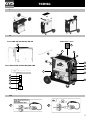
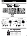
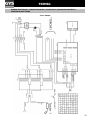
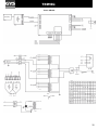
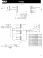
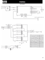
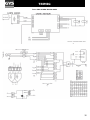
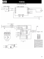
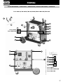
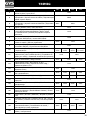
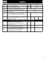
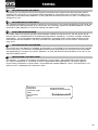
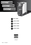
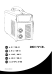
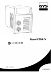
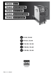
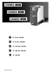
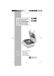
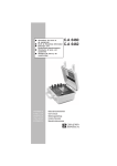
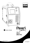
en P 9-13 / 31-44 www.gys.fr 73502 - V4 - 03/09/13 TRIMIG I II Trimig 200-4S/250-4S DV/300-4S Trimig 300 G / 350 G 12 18 13 10 5 6 7 Trimig 300 G/350-4S DUO DV/350 G DV 1 11 3 2 9 4 12 14 8 15 16 17 III A B 2 TRIMIG IV 1 2 3 5 7 6 4 8 9 V Trimig 200 Trimig 250/300/350 1 1 4 2 4 2 5 3 5 3 VI 3 TRIMIG EN description Thank you for choosing this product; please read this instruction manual carefully before installing and using the product and keep in a safe place for future reference. The Trimig are semi-automatic welding units; they are ventilated for semi-automatic welding (MIG or MAG) and are capable of welding steel, stainless steel and aluminium. Adjustment is quick and easy with their «synergic wire speed» function. They work on a 400V three-phase power supply, and /or 230V three-phase for the DV models. electricity supply The absorbed current (I1eff) is indicated on the device for use at maximum settings. Check that the power supply and its protection (fuse and/or circuit breaker) are compatible with the current needed during use. The device must be placed in such way that the power socket is always accessible. Do not use an extension cable which has a wire section smaller than 4 mm². These products are supplied with a 16A or 32A plug type EEC RS/015. They should be plugged in to a 400V (3PH) power socket WITH earth and protected by a 16A circuit breaker and 1 differential 30mA. 230V 3-phase power supply, for Trimig 250-4S DV, 350 G DV and 350-4S DUO DV: WARNING: This device is pre-built in 400V three-phase. If your electrical installation is 230V three-phase, you must modify the connection on the terminal board. This modification must be undertaken by qualified personnel. In order to do so, please refer to the technical diagram inside the product. The plug must be protected by a 16A or 25A (for models 350) circuit breaker and 1 differential 30mA. device presentation (fig ii) 1- On / Off switch 2- Power Settings - 2 switches with 7 positions: for adjustment of the welding voltage output. The adjustment of the output voltage is proportional to the thickness of the work piece. 3- Control panel – Welding settings (manual or automatic mode). 4- European standard torch connection. 5- Thermal Protection light: Indicates when a cool-down period is necessary following intensive use. 6- Torch support. 7- Power Cable (5m). 8- Earth cable connector 9- Gas bottle support (max 1 bottle of 10m3). 10- Fastening chain for bottles. Warning: fasten the chain securely (see IV-1) 11- Reel support Ø 200 mm/ 300mm. 12- Gas connector (350-4S DUO DV) 13- Torch Cable support 14- Wire feeder solenoid valve 2 15- Wire feeder gas connection for torch 2 16- Wire feeder control cable connector 17- Wire feeder power cable connector 18- Selection switch potentiometer (only on 300G and 350 G DV) SEMI-AUTOMATIC WELDING FOR STEEL / STAINLESS STEEL (MAG MODE) (fig iii) The Trimig 200-4S can weld 0.6/0.8/1mm steel and stainless steel wires (fig. III-A). The device is capable of working with Ø 1.0 mm steel wire (roller Ø 0.8/1.0, contact tip of 01.0). If using lower diameter wire, you should use change the contact tip, and ensure that the reversible rollers in the wire feeder are positioned correctly (so that required diameter is visible when in place). The Trimig 250-4S DV 230-400V can weld 0.8/1/1.2mm steel and stainless steel wires. The device is capable of working with Ø 1mm steel wire (roller Ø 0.8/1.0, contact tip of 1). The Trimig 300-4S, 300 G, 350-4S DUO DV and 350 G DV can weld 0.8/1/1.2mm steel and stainless steel wires. The device is capable of working with Ø 1mm steel wire (roller Ø 1.0/1.2, contact tip of 1). For Steel or Stainless Steel, you will need to use specific gas - Argon + CO2 (Ar + CO2). The proportion of CO2 will vary depending on usage. The gas flow for steel is between 10 and 20L / min depending on the environment and experience of the welder. SEMI-AUTOMATIC WELDING FOR ALUMINIUM (MIG MODE) (fig iii) The Trimig 200-4S can weld 0.8mm and 1mm aluminium wires. (fig. III-B). The Trimig 250, 300 and 350 can weld 1mm and 1.2mm aluminium wires. (fig. III-B). To weld aluminium, neutral gas “pure Argon” (AR) is required. For specific gas requirements seek advice from your gas distributor. The gas flow in aluminium should be between 15 and 25 L / min depending on the environment and experience of the welder. Things to note when welding with Aluminium - Set the pressure of the rollers to a minimum so as not to crush the wire - Remove the capillary tube before connecting the aluminium torch - When welding aluminium use a special aluminium torch with Teflon sheath to reduce friction. 9 TRIMIG EN Do not cut the sheath near the connector! It is used to guide the wire from the rollers (fig III-B). - Contact Tip: Use the specific Aluminium contact tip corresponding to the diameter of the wire. SEMI-AUTOMATIC BRAZING FOR HIGH-TENSILE STRENGTH STEELS The Trimig 200-4S can braze-weld high-tensile strength plates with Cuprosilicium CusI3 wire or Cuproaluminium CuAl8 wire (Ø 0.8 mm and Ø 1 mm). The welder must use a neutral gas: pure argon (Ar). For specific gas requirements seek advice from your gas distributor. The required gas flow is between 15 and 25L / min. REEL AND TORCH ASSEMBLY (fig iv) Open the door of the machine. • Position the reel on to the support (3). To place a 200mm wire reel, first install the adapter (ref. 042889) on the support. • Adjust the reel brake (4) to avoid the reel movement tangling the wire when welding stops. Be careful not to tighten too much! Then tighten the plastic screw (2) firmly. • The wire feeder uses double groove rollers (8) (Ø 0.8/ Ø 1 or Ø 1/ Ø 1.2). The visible diameter on the roller when fitted is the one currently in use. For Ø 1 mm wire, use the Ø 1 groove. • For first use: - Release the fixing screw of the wire guide (5). - Place the rollers, and tighten the screws (9). - Place the wire guide (7) as close as possible to the roller but without touching it, then tighten the fixing screw. • To select the adjustment of the drive rollers (6) : loosen the knob fully, Start the motor by pressing the trigger of the torch, tighten the knob whilst pressing the trigger until the wire starts to move. Bend the wire where it comes out of the nozzle and hold it in place to stop its progress. The setting is correct when the guide roller slides over the wire, even when it is blocked at the end of the torch. • Common adjustment of knob (6): scale 3-4 for steel, and scale 2-3 for aluminium. CHOICE OF REELS Possible settings: Wire type Torch Gas Ø 300 x Ø 200 x Stainless Ø 200 x argon + CO2 Alu AG5 Ø 300 x* Ø 200 x* Steel Argon pur *Consider Teflon sheath and special aluminium contact tip GAS COUPLING Fit the regulator/flowmeter to the gas bottle and then fit the gas pipe to the connector. To avoid gas leaks use the collars provided in the accessories box. Ensure proper maintenance of the gas cylinder in accordance with the attachment of the chain cf. IV-1. CONTROL PANEL (fig v) Welding mode selection (2) - 2T: two-stage welding - 4T: 4-stage welding - SPOT: Spot welding with adjustable spot diameter Wire speed selection (4) Wire speed regulator The speed varies from 1 to 15 m/minute. SPOT/DELAY setting potentiometer (5) Manual Mode (1) In manual mode, the wire speed is determined by the user by adjusting the potentiometer (4). Synergic Mode (3) Position the potentiometer (4) in the middle of the « OPTIMAL SYNERGIC » zone In this mode, the device determines the optimum wire speed according to 3 parameters: - Voltage - Wire diameter - The power mode It is possible to adjust the speed wire + / -. 10 TRIMIG EN "manual" mode (fig v) To set your device, proceed as follows: - Choose the welding voltage using the 2 power switches (2 and 7 positions) Example: For welding Steel - 1 mm with a Ø 0.8 wire, set the switch to «1» Adjust the wire speed with potentiometer (4). Advice: The wire speed adjustment is often determined by « the noise »: the arc must be stable and emit low crackling. If the speed is too low, the arc will not be continuous. If the speed is too high, the arc crackles and the wire will push back the torch. "synergic" mode (fig v) This function automatically controls the wire speed. There is no need to set the wire speed manually. • Position the wire speed potentiometer (4) in the middle of the « Optimal synergic » zone. • Select: - Wire type (3) - Wire diameter (3) - Power setting (switch on the front) To select the right position in accordance with the thickness of the work-piece, please refer to the “synergic mode” table on the previous page. From the settings chosen, the Trimig determines the optimum wire speed and the device is ready to weld. It is also possible to adjust the wire speed if necessary by adjusting potentiometer + or – manually (4). The last welding configuration is saved in the memory automatically (wire diameter, wire type, mode). ADVICE and THERMAL PROTECTION • Trimig should not be lifted by its handles, torch support, or the top of the machine. When lifting the Trimig, ensure the weight is fully supported at the bottom of the machine. There must be no gas bottle connected during this operation. • Always respect the basic rules of welding. • Do not block/cover the ventilation holes of the machine. • Leave the device plugged in after welding to allow proper cooling down. • Thermal protection: If the machine becomes too hot, the warning light will illuminate and the machine will stop. Cooling will take a few minutes, the length of time will also depend on the external temperature. DUTY CYCLE and WELDING ENVIRONMENT IN USE • The welding unit describes an output characteristic of "constant current" type. The duty cycles following the standard EN60974-1 (at 40°C on a 10mn cycle) are indicated in the table below: x/60974-1 @ 40°C I max 60% 100% Trimig 200-4S 200A @ 30% 140A 120A Trimig 250-4S 250A @ 30% 180A 140A Trimig 300-4S et G 300A @ 35% 240A 180A Trimig 350-4S DUO et G DV 350A @ 35% 270A 220A Note : The machines’ duty cycle has been tested at room temperature (40°C) and has been determined by simulation. • These are Class-A devices. They are designed to be used in an industrial or professional environment. In a different environment, it can be difficult to ensure electromagnetic compatibility, due to conducted disturbances as well as radiation. • These devices comply with IEC 61000-3-12, provided that the power of the short-circuit Ssc is equal to or greater than 3.9MVA (2.8MVA for the Trimig 200-4S) at the interface between the machine and the mains power network. It is the responsibility of the installer or user of the equipment to ensure if necessary by consulting the operator of the mains electricity, that the equipment is only connected to a power supply where the power of short-circuit ssc is equal to or greater than 3,9MVA (2.8MVA for the Trimig 200-4S). 11 TRIMIG EN Maintenance • Maintenance should only be carried out by a qualified person. • Ensure the machine is unplugged, and that the ventilator inside has stopped before carrying out maintenance work. (DANGER High Voltage and Currents). • GYS recommends removing the steel cover 2 or 3 times a year to remove any excess dust. Take this opportunity to have the electrical connections checked by a qualified person with an insulated tool. • Regularly check the condition of the power supply cord. If damaged, it will need to be replaced by the manufacturer, its’ after sales service or a qualified person. • Ensure the ventilation holes of the device are not blocked to allow adequate air circulation. • Before each use, check the state of welding cables of the torch and earth clamp (The conductive metal should not be exposed). SAFETY Arc welding can be dangerous and can cause serious and even fatal injuries. Protect yourself and others. Ensure the following safety precautions are taken: Arc radiation: Protect yourself with a helmet fitted with filters in compliance with EN169 or EN 379. Rain, steam, damp: Use your welding unit in a clean/dry environment (pollution factor ≤ 3), on a flat surface, and more than one meter from the welding work-piece. Do not use in rain or snow. Electric choc: This device must only be used with an earthed power supply. Do not touch the parts under high voltage. Check that the power supply is suitable for this unit. Falls: Do not place/carry the unit over people or objects. Burns: Wear protective (fire-proof) clothing (cotton, overalls or jeans). Wear protective gloves and a fire-proof apron. Ensure other people keep a safe distance from the work area and do not look directly at the welding arc. Protect others by installing fire-proof protection walls. Fire risks: Remove all flammable products from the work area. Do not work in presence of flammable gases. Fumes: Do not inhale welding gases and fumes. Use the device in a well ventilated environment, with artificial extraction if welding indoors. Additional Precautions: Any welding operation undertaken in..... - rooms where there is an increased risk of electric shocks, - Poorly ventilated rooms, - In the presence of flammable or explosive material, Use should always be approved by a "responsible expert", and made in presence of people trained to intervene in case of emergency. Technical protection as described in the Technical Specification CEI/IEC 62081 must be implemented. Welding in raised positions should not be undertaken, except in case of safety platforms use. People wearing Pacemakers are advised to see their doctor before using this device. Do not use the welding unit to unfreeze pipes. Handle gas bottles with care - there is increased danger if the bottle or its valve are damaged. 12 TRIMIG EN TROUBLESHOOTING Symptoms Reasons Cracklings block up the opening. Clean out the contact batch or change it and replace the anti-adherence product. Ref.041806 The wire skids in the rollers. Control the roller pressure or replace it. Wire diameter non-consonant with roller. Covering Wire guide in the torch nonconsonant. Reel or roller brake too tight. Release the brake and rollers. Electrical supply problem. Check that the running button is on the position on. The welding wire speed is not constant. The unwinding motor doesn't operate. Bad wire unwinding. No welding current The wire rubs down after the rollers. The welding cord is porous Solutions Covering wire guide dirty or damaged. Clean or replace Reel brake too tight Release the brake Bad connection to the main supply. See the branch connection and look if the plug is fed by 3 phases. Bad earth connection. Control the earth cable (connection and clamp condition). Power contactor inoperative. Control the torch trigger. Covering wire guide crushed. Check the covering and torch body. Locking of the wire in the torch Clean or replace. No capillary tube. Check the presence of capillary tube. Wire speed too fast Reduce the wire speed The gas flow rate is not sufficient. Adjusting flow range 15 to 20 L / min. Clean the working metal. Gas bottle empty. Replace it. Gas quality non-satisfying. Replace it. Air flow or wind influence. Avert air blast, protect welding area. Gas nozzle too full. Clean or replace the gas nozzle. Bad wire quality. Use adapted WIRE for MIG-MAG welding. Surface to weld in bad condtion. (rust, Clean the working parts before etc, ...) welding. Very important flashing particules. No gas at the torch output. Arc voltage too low or too high. See welding settings. Bad earth connection. Check and place the earth cable to have a better connection. Protecting gas insufficient. Adjust the gas flow. Bad gas connection. See if the gas coupling beside the engine is well connected. Check the flowmeter and the solenoid valves. 13 TRIMIG SCHÉMA ÉLECTRIQUE / CIRCUIT DIAGRAM / SCHALTPLAN / DIAGRAMA ELECTRICO / ЭЛЕКТРИЧЕСКАЯ СХЕМА Trimig 200-4S 31 TRIMIG Trimig 250-4S 32 TRIMIG Trimig 300-4S 33 TRIMIG Trimig 300 G 34 TRIMIG Trimig 350-4S DUO DV 230-400V 35 TRIMIG Trimig 350 G DV 230-400V 36 TRIMIG PIECES DETACHEES / SPARE PARTS / ERSATZTEILE/ PIEZAS DE RECAMBIO/ ЗАПЧАСТИ Trimig 200-4S/250-4S DV/300-4S/300 G/350-4S DUO DV/350 G DV 2 28 27 7 3 5 1 6 12 33 13 8 Trimig 300 G Trimig 350 G DV 10 11 20 21 21 29 14 4 26 24 25 23 32 26 31 22 32 15 17 19 18 16 29 Trimig 300 G Trimig 350-4S DUO DV Trimig 350 G DV 37 TRIMIG N° 200 250 300 1 Chaîne de 80cm / 80cm chain / 80cm Sicherungskette / cadena de 80cm / Цепь 80 см 35067 2 Support câbles arrière / Rear cable support / Hinterer Brennerhalter / Soporte trasero de cables / Подставка для каблей горелок задняя 98854 3 Support torches avant / Front torches support / Vorderer Brennerhalter / Soporte antorchas delanteras / Подставка для горелок 4 Poignée / Handle / Griff / Puño/ Рукоятка 56047 5 Bouton réglage de vitesse fil / Wire speed adjusting knob / Poti Drahtvorschubgeschwindigkeit / Botón reglaje de velocidad de hilo / Кнопка регулировки скорости проволоки 73009 6 Bouton SPOT-DELAY / SPOT-DELAY button / SPOT-DELAY Poti / botón SPOT/DELAY / Кнопка SPOT-DELAY 73099 7 Clavier de commande / Control Keyboard / Bedienfeld / Teclado de mando / Панель управления 8 Interrupteur I/O / I/O Switch / Netzschalter AN/AUS / Conmutador ON/OFF / Переключатель Вкл/Выкл 98853 350 98877 51916 51915 52461 10 Commutateur / Switch / Spannungsschalter / Conmutador / переключатель 11 Motodévidoire (sans galet) / Wire feeder (without roller) / Drahtvorschub (ohne Drahtförderrollen) / Devanadera sin rodillos (sin rodillo) / Подающий механизм (без роликов) 12 Câble d'alimentation / Supply cable / Netzstromkabel / Cable de alimentación / Шнур питания 13 Support bobine 15Kg / Reel support 15 Kg / Drahtförderrollen 15Kg / Soporte de bobina 15Kg / Держатель бобины 15 кг 14 Roue avant / Front wheels / Vorderrad / Rueda de atrás / Переднее колесо 71361 15 Pont de diodes / Diode bridge / Gleichrichter / Puente de LED / Диодный мост 52190 52173 52174 52221 16 Self / Induction oil / Self / Drossel / Дроссель 96076 96079 96081 96083 17 Thermostat / Thermostat / Thermostat / termostato / Термостат 18 Transformateur / Transformer / Trafo / Transformador / Транформатор 19 Ventilateur / Fan / Ventilator /ventilador/ Вентилятор 20 Roue diamètre 200mm / 200mm diameter wheels / Rad 200mm Durchmesser / Rueda diámetro 200mm / Колесо диаметром 200 мм 21 Embout d'axe / End axis / Radachse / Boquilla de pasador / Ось 22 Contacteur 24V AC 10A / Contactor 24V AC 10A / 24V AC 10A Schalter / Contactor 24V AC 10A / Контактор 24В AC 10A 23 Transformateur de commande / Control transformer / Steuertransformator / Transformador de mando / Трансформатор цепей управления 24 Electrovanne / Solenoid valve / Elektroventil / Electroválvula / Электроклапан 7 pos 10 pos 12 pos 7 pos 51054 51072 51074 51227 2 pos 51071 51136 51257 21475 21497 21470 71603 71364 52101 96075 96078 96080 96082 51006 71375 71376 71382 51114 92994 51107 96029 96047 96029 71512 38 TRIMIG 25 Carte de commande / Control card / Steuerkarte / Carta de mando / Плата управления 97132C 97172C 26 Carte d'affichage / Display card / Anzeigekarte / Carta de fijación / Плата управления дисплея 97183C 97233C 27 Tuyau gaz (1m) / Gas pipe (1m) / Gasschlauch (1m) / Tubo del gas (1m) / Газопроводная трубка (1 м) 95993 28 Collier 10,5 / Collar 10,5 / Schlauchschelle 10,5 / Collar 10,5 / Хомут 10,5 71225 29 Connecteur 1/4 cable de masse / Earth cable connector (1/4) / (-) Texasbuchse (1/4) - Leistungsanschluss separates Drahtvorschubgerät/ connector cable de tierra (1/4) 51469 30 Sélecteur 230-400V / Voltage selection switch 230-400V/ Umschalter 230-400V / Selector de tensiόn 230/400V / Переключатель 230-400В - 51461 75012 - 75012 Pour les postes avec dévidoir / For machines with wire feeder / Geräte mit separatem Drahtvorschubgerät / Para equipos con devanadera / для аппаратов с подающим устройством 31 Passe cloison de Gaz / Gas connector / Schutzgasanschluss 2 (Ausgang für separates Drahtvorschubgerät) / Conector de gas / Проход в перегородке для Газа - - 71699 32 Connecteur de commande / Wire feeder control connector / Steueranschluss separates Drahtvorschubgerät / Conector de mando / Коннектор управления - - 94895 33 Interrupteur de sélection du potentiomètre / Potentiometer selection switch / Potentiometer Auswahlschalter/ Interruptor de selecciόn del potenciόmetro / Переключатель выбора на потенциометре - - 52464 39 TRIMIG conditions de garantie France - La garantie n’est valable que si le bon a été correctement rempli par le vendeur. - La garantie couvre tout défaut ou vice de fabrication pendant 1 an, à compter de la date d’achat (pièces et main d’œuvre). - La garantie ne couvre pas les erreurs de tension, incidents dus à un mauvais usage, chute, démontage ou toute autre avarie due au transport. - La garantie ne couvre pas l’usure normale des pièces (Ex. : câbles, pinces, etc.). En cas de panne, retournez l’appareil à la société GYS (port dû refusé), en y joignant : - Le présent certificat de garantie validé par le vendeur. - Une note explicative de la panne. Après la garantie, notre SAV assure les réparations après acceptation d’un devis. Contact SAV: Société GYS - 134 Bd des Loges BP 4159-53941 Saint-Berthevin Cedex Fax: +33 (0)2 43 01 23 75 - Tel: +33 (0)2 43 01 23 68 herstellergarantie Die Garantieleistung des Herstellers erfolgt ausschließlich bei Fabrikations- oder Materialfehlern, die binnen 12 Monate nach Kauf angezeigt werden (Nachweis Kaufbeleg). Nach Anerkenntnis des Garantieanspruchs durch den Hersteller bzw. seines Beauftragten erfolgen eine für den Käufer kostenlose Reparatur und ein kostenloser Ersatz von Ersatzteilen. Der Garantiezeitraum bleibt aufgrund erfolgter Garantieleistungen unverändert. Ausschluss: Die Garantieleistung erfolgt nicht bei Defekten, die durch unsachgemäßen Gebrauch, Sturz oder harte Stöße sowie durch nicht autorisierte Reparaturen oder durch Transportschäden, die infolge des Einsendens zur Reparatur, hervorgerufen worden sind. Keine Garantie wird für Verschleißteile (z. B. Kabel, Klemmen, Vorsatzscheiben etc.) sowie bei Gebrauchsspuren übernommen. Das betreffende Gerät bitte immer mit Kaufbeleg und kurzer Fehlerbeschreibung ausschließlich über den Fachhandel einschicken. Die Reparatur erfolgt erst nach Erhalt einer schriftlichen Akzeptanz (Unterschrift) des zuvor vorgelegten Kostenvoranschlags durch den Besteller. Im Fall einer Garantieleistung trägt GYS ausschließlich die Kosten für den Rückversand an den Fachhändler. 40 TRIMIG FR déclaration de conformité GYS atteste que ces postes de soudure sont fabriqués conformément aux exigences des directives Basse tension 2006/95/CE du 12/12/2006, et aux directives CEM 2004/108/CE du 15/12/2004. Cette conformité est établie par le respect des normes harmonisées EN60974-1 de 2005, EN 50445 de 2008, EN 60974-10 de 2007. Le marquage CE a été apposé en 2013. declaration of conformity The equipment described on this manual is conform to the instructions of low voltage 2006/95/CE of 12/12/2006, and the instructions of CEM 2004/108/CE of the 15/12/2004. This conformity respects the standards EN60974-1 of 2005, EN 50445 de 2008, EN60974-10 of 2007. CE marking was added in 2013. EN DE Konformitätserklärung GYS erklärt, dass die synergisch geregelten Schweißanlagen TRIMIG 200-4S/ 250-4S DV/ 300-4S/ 300 G/ 350-4S DUO DV/ 350 G DV richtlinienkonform mit Niederspannungsrichtlinie 2006/95/CE –12.12.2006 und EMV- Richtlinien 2004/108/CE – 15.12.2004 elektromagnetische Verträglichkeit- hergestellt wurden. Diese Geräte stimmen mit den harmonisierten Normen EN60974-1 von 2005, EN 50445 von 2008, EN60974-10 von 2007 überein. CE Kennzeichnung: 2013. declaración de conformidad GYS certifica que estos aparatos de soldadura son fabricados en conformidad con las directivas baja tensión 2006/95/ CE del 12/12/2006, y las directivas compatibilidad electromecánica 2004/108/CE del 15/12/2004. Esta conformidad está establecida por el respeto a las normas EN60974-1 de 2005, EN 50445 de 2008, EN 60974-10 de 2007. El marcado CE fue fijado en 2013. ES RU Декларация о соответствии GYS заявляет, что сварочные аппараты произведены в соответствии с директивами Евросоюза 2006/95/ CE о низком напряжении от 12/12/2006, а также с директивами CEМ 2004/108/CE от 15/12/2004. Данное соответствие установлено в соответствии с согласованными нормами EN60974-1 2005 г, EN 50445 2008 г, EN 60974-10 2007 г. Маркировка ЕС нанесенна в 2013 г. 01/02/2013 Société GYS 134 BD des Loges 53941 Saint-Berthevin France Nicolas BOUYGUES Président Directeur Général 41 TRIMIG icones / SYMBOLS / Zeichenerklärung A Ampères - Amps - Ampere - Amperios - Ампер V Volt - Volt - Volt - Voltios - Вольт Hz Hertz - Hertz - Hertz - Hertz - Герц Soudage MIG/MAG (MIG: Metal Inert Gas / MAG: Metal Active Gas) - MIG/MAG Welding (MIG: Metal Inert Gas / MAG: Metal Active Gas) - MIG/MAG Schweißen (MIG: Metal Inert Gas/ MAG: Metal Active Gas) - Soldadura MIG/MAG (MIG: Metal Inert Gas / MAG: Metal Active Gas) - Полуавтоматическая сварка MIG/MAG (MIG: Metal Inert Gas / MAG: Metal Active Gas) Convient au soudage dans un environnement avec risque accru de choc électrique. La source de courant elle-même ne doit toutefois pas être placée dans de tels locaux. - Adapted for welding in environment with increased risks of electrical shock. However, the welding source must not be placed in such places. - S-Zeichen: Das Schweißen unter beengten Verhältnissen ist mit diesen Schweißgeräten zugelassen.- Adaptado a la soldadura en un entorno que comprende riesgos de choque eléctrico. La fuente de corriente ella misma no debe estar situada dentro de tal locales. - Адаптирован для сварки в среде с повышенным риском электрошока. Однако сам источник питания не должен быть расположен в таких местах. IP21 Protégé contre l’accès aux parties dangereuses avec un doigt, et contre les chutes verticales de gouttes d'eau. - Protected against rain and against fingers access to dangerous parts. - Schutz gegen Berührung mit den Fingern und mittelgroße Fremdkörper, Schutz gegen Tropfwasser. - Protegido contra el acceso a las partes peligrosas con los dedos, y contra las caídas verticales de gotas de agua. - Аппарат защищен от доступа рук в опасные зоны и от вертикального падения капель воды Сварка на постоянном токе. Courant de soudage continu. - Welding direct current. - Gleichschweißstrom. - La corriente de soldadura es continua. - Сварка на постоянном токе. Alimentation électrique triphasée 50Hz. - Three-phase power supply 50 Hz. - Dreiphasige Netzversorgung mit 50 Hz. - Alimentación eléctrica monofásica 50 Hz. - Трехфазное напряжение 50 Гц. U0 Tension assignée à vide. - Rated no-load voltage. - Leerlaufspannung. - Tensión asignada de vacío. Напряжение холостого хода. U1 Tension assignée d’alimentation. - rated supply voltage. - Netzspannung. - Tensión de la red. Напряжение сети. I1max I1eff EN60 974-1 Courant d’alimentation assigné maximal (valeur efficace). - Rated maximum supply current (effective value). - Maximaler Versorgungsstrom (Effektivwert). - Corriente máxima de alimentación de la red. Максимальный сетевой ток (эффективная мощность) Courant d’alimentation effectif maximal. - Maximum effective supply current. - Maximaler tatsächlicher Versorgungsstrom. - Corriente de alimentación efectiva máxima. - Максимальный эффективный сетевой ток. L’appareil respecte la norme EN60974-1. - The device complies with EN60974-1 standard relative to welding units. - Das Gerät entspricht der Norm EN60974-1 für Schweißgeräte. - El aparato está conforme a la norma EN60974-1 referente a los aparatos de soldadura. - Аппарат соответствует европейской норме EN60974-1. Transformateur-redresseur triphasée. - Three-phase converter-rectifier. - Dreiphasiger Trafo/Frequenzumwandler. - Transformador-rectificador trifásico. - Трехфазный инвертор, с трансформацией и выпрямлением. X(40°C) Facteur de marche selon la norme EN 60974-1 (10 minutes – 40°C). - Duty cycle according to the standar EN 60974-1 (10 minutes – 40°C). - Einschaltdauer gemäß EN 60974-1 (10 Minuten – 40°C). - Factor de marcha según la norma EN 60974-1 (10 minutos – 40°C). - ПВ% по норме EN 60974-1 (10 минут – 40°С). I2: courant de soudage conventionnnel correspondant. - I2: corresponding conventional welding current. - I2: entsprechender Schweißstrom. - I2: Corrientes correspondientes. - I2: Токи, соответствующие Х* U2: Tensions conventionnelles en charges correspondantes. - U2: conventional voltages in corresponding load. - U2: entsprechende Arbeitsspannung. - U2: Tensiones convencionales en carga. - U2: соответствующие сварочные напряжения*. 42 TRIMIG Appareil conforme aux directives européennes. - The device complies with European Directive. - Gerät entspricht europäischen Richtlinien. - El aparato está conforme a las normas europeas. Устройство соответствует европейским нормам. Conforme aux normes GOST (Russie). - Conform to standards GOST / PCT (Russia). - in Übereinstimmung mit der Norm GOST/PCT. - Conforme a la normas GOST (PCT) (Rusia). - Продукт соответствует стандарту России (РСТ). L’arc électrique produit des rayons dangereux pour les yeux et la peau (protégez-vous !). - The electric arc produces dangerous rays for eyes and skin (protect yourself !). - Der elektrische Lichtbogen verursacht Strahlungen auf Augen und Haut (Schützen Sie sich !). - El arco produce rayos peligrosos para los ojos y la piel (¡ Protéjase !). - Электрическая дуга производит опасные лучи для глаз и кожи (защитите себя!). - Внимание! Сварка может вызвать пожар или взрыв. Attention, souder peut déclencher un feu ou une explosion. - Caution, welding can produce fire or explosion. - Achtung! Schweißen kann Feuer oder Explosion verursachen. - Cuidado, soldar puede iniciar un fuego o una explosión. - Внимание! Сварка может вызвать пожар или взрыв. Attention ! Lire le manuel d’instruction avant utilisation. - Caution ! Read the user manual. - Achtung! Lesen Sie die Betriebsanleitung. - Cuidado, leer las instrucciones de utilización. - Внимание ! Читайте инструкцию по использованию. Produit faisant l'objet d'une collecte sélective- Ne pas jeter dans une poubelle domestique. - Separate collection required, Do not throw in a domestic dustbin. - Für die Entsorgung Ihres Gerätes gelten besondere Bestimmungen (Sondermüll). Es darf nicht mit dem Hausmüll entsorgt werden. - Este aparato es objeto de una recolección selectiva. No debe ser tirado en un cubo doméstico. - Продукт требует специальной утилизации. Не выбрасывать с бытовыми отходами. 43 TRIMIG Accessoires/accesories/zubehör/accesorios/akceccyapbi Trimig 200-4S ø 200 ø 300 Acier/Steel/Stahl 086111 (ø0.6) 086126 (ø0.8) 086135 (ø1.0) 086166 (ø0.6) 086227 (ø0.8) 086234 (ø1.0) Inox/Stainless/ Edelstahl 086325 (ø0.8) - CuSi3 086647 (ø0.8) - CuAl8 086661 (ø0.8) - Alu 086565 (ø0.8) 086524 (ø1.0) 0.6 - 1.0 042353 (ø0.6/0.8) 042360 (ø0.8/1.0) 042377 (ø0.8/1.0) 041837 (ø0.6/0.8 - 4m) 041844 (ø1.0 - 4m) 044050 (ø0.8 - 4m) 044067 (ø1.0 - 4m) 040922 (250A - 4m) 041905 (ø0.6) 041950 (ø0.8) 041967 (ø1.0) 20L/min 041998 041882 040939 (250A - 4m) 30L/min 041622 (FR) 041646 (UK) 041219 (DE) 043787 (250A - 3m) 25 mm² 041059 (ø0.8) 041066 (ø1.0) Trimig 250-4S DV 230-400V ø 200 ø 300 Acier/Steel/Stahl 086128 (ø0.8) 086135 (ø1.0) 086227 (ø0.8) 086234 (ø1.0) 086241 (ø1.2) Inox/Stainless/ Edelstahl 086326 (ø0.8) - Alu - 086524 (ø1.0) 086531 (ø1.2) 0.8 - 1.2 042360 (ø0.8/1.0) 042384 (ø1.2/1.6) 042377 (ø0.8/1.0) 042391 (ø1.2/1.6) 041837 (ø0.8 - 4m) 041844 (ø1/1.2 - 4m) 044050 (ø0.8 - 4m) 044067 (ø1.0 - 4m) 044074 (ø1.2 - 4m) 040922 (250A - 4m) 041950 (ø0.8) 041967 (ø1.0) 041974 (ø1.2) 041882 040939 (250A - 4m) 30L/min 041622 (FR) 041646 (UK) 041219 (DE) 043787 (250A - 3m) 25 mm² 041066 (ø1.0) 041073 (ø1.2) Trimig 300-4S / 300 G / 350-4S DUO DV / 350 G DV ø 200 ø 300 Acier/Steel/Stahl 086128 (ø0.8) 086135 (ø1.0) 086227 (ø0.8) 086234 (ø1.0) 086241 (ø1.2) Inox/Stainless/ Edelstahl 086326 (ø0.8) - Alu - 086524 (ø1.0) 086531 (ø1.2) 0.8 - 1.2 042360 (ø0.8/1.0) 042384 (ø1.2/1.6) 042377 (ø0.8/1.0) 042391 (ø1.2/1.6) 041837 (ø0.8 - 4m) 041844 (ø1/1.2 - 4m) 044050 (ø0.8 - 4m) 044067 (ø1.0 - 4m) 044074 (ø1.2 - 4m) 040946 (350A - 4m) 043800 (300A - 4m) 25 mm² 041790 (ø0.8) 419803 (ø1.0) 419810 (ø1.2) 041783 040953 (350A - 4m) 419766 (ø1.0) 419773 (ø1.2) 30L/min 041622 (FR) 041646 (UK) 041219 (DE) 043817 (400A - 4m) 35 mm² 043824 (500A - 4m) 50 mm² 44