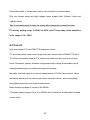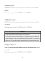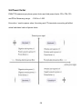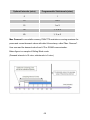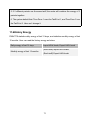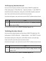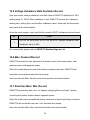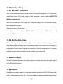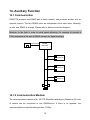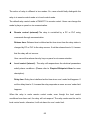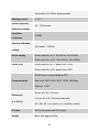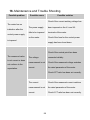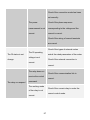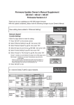
1
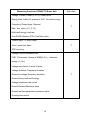
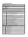
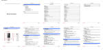
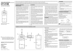
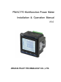
PMAC770 Multifunction Power Meter Installation & Operation Manual V3.0 ZHUHAI PILOT TECHNOLOGY CO., LTD. Danger and warning! This device can be installed only by professionals. The manufacturer shall not be held responsible for any accident caused by the failure to comply with the instructions in this manual. Risks of electric shocks, burning, or explosion This device can be installed and maintained only by qualified people. Before operating the device, isolate the voltage input and power supply and short-circuit the secondary windings of all current transformers. Use appropriatevoltage tester to make sure the voltage has been cut-off. Put all mechanical parts, doors, or covers in their original positions before energizing the device. Always supply the device with the correct working voltage during its operation. Failure to take these preventive measures could cause damage to equipment or injuries to people. Operating environment Operating temperature: -10℃~+55℃ Storage temperature: -40℃~+70℃ Relative humidity: 5%~95%,non-condensing Height: ≤2000m Operating power supply: (Have 2 options, please check the label on the meter) (1) 85Vac ~265Vac, 85Vdc ~265Vdc, 45-65Hz,10VA 2 (2) 100~420Vac, 100~400Vdc, 45~60Hz,10VA MAINS supply voltage fluctuations up to ±10 % of the nominal voltage Pollution degree: 2 The product is for indoor use only. Meaning of the symbols Attention! This symbol warns you of dangers that could occur during assembly, commissioning and operation. Dangerous voltage! Risk of death or serious injury. Disconnect the power before working on the system and device. This Listing Mark is used for products going into the Canadian and US marketplace. It shows that compliance with both Canadian and US requirements for listed products has been met. 3 A double insulated electrical appliance means product no only use basic insulation to prevent electric shock, but also including safety measure, such as double insulation or reinforced insulation, but earth protection or protection based on installation conditions is not included. 4 CONTENTS 1. General Information........................................................................................ 8 2. Order Information.............................................................................................. 11 3. Packing list......................................................................................................13 4. Figure and Terminals......................................................................................... 14 4.1 Dimension............................................................................................. 14 4.2Installation..............................................................................................14 4.3 Terminals............................................................................................... 15 5. Connection Mode and Wiring............................................................................23 6. Display and Key-press Operation...................................................................... 27 6.1 Display Instruction................................................................................ 27 6.2 Keys.......................................................................................................28 6.3 Map of Display Data............................................................................. 29 7. Query Procedure................................................................................................ 30 7.1 Initial Display........................................................................................30 7.2 Voltage Value.........................................................................................31 7.3 Current Value.........................................................................................33 7.4 Frequency.............................................................................................. 34 7.5 Power Value...........................................................................................35 7.6 Energy................................................................................................... 36 7.7 Harmonic...............................................................................................37 7.8 Demand................................................................................................. 39 7.9 Analog Input (Optional)........................................................................ 41 5 7.10 Running time display.......................................................................... 41 8. Setting................................................................................................................ 42 8.1 Instruction..............................................................................................42 8.2 Setting Site-map.................................................................................... 43 8.3 COM—Communication Setting Menu................................................. 49 8.4 CLEAR—Clearing Data Menu............................................................. 49 8.5 RELAY—Relay Setting Menu..............................................................50 8.6 AO—Analog Output Setting Menu (Optional)..................................... 51 8.7 LIMIT—Deviation Limit Setting Menu............................................... 52 8.8 ERROR..................................................................................................53 9. Measuring Function Description....................................................................... 54 9.1 Voltage...................................................................................................55 9.2 Current...................................................................................................56 9.3 Active power......................................................................................... 57 9.4 Reactive power......................................................................................57 9.5 Apparent power..................................................................................... 57 9.6 Power factor.......................................................................................... 58 9.7 Frequency.............................................................................................. 59 9.8Phase Angle............................................................................................ 59 9.9 Demand calculation...............................................................................59 9.10 Phase sequence detect......................................................................... 61 10. Power Quality Analysis................................................................................... 62 10.1General Description..............................................................................63 10.2 THD.....................................................................................................63 6 10.3 Harmonic Ratio for Voltage................................................................ 63 10.4 Harmonic Ratio for Current................................................................ 63 10.5Voltage Crest Factor............................................................................. 64 10.6 Current K Factor..................................................................................64 10.7 Harmonic Voltage RMS...................................................................... 64 10.8 Harmonic Current RMS...................................................................... 65 10.9 Harmonic Power RMS........................................................................ 65 10.10 Harmonic Energy.............................................................................. 65 10.11 Frequency Deviation......................................................................... 65 10.12 Voltage Deviation.............................................................................. 66 10.13 Voltage Unbalance Rate.................................................................... 66 10.14 Current Unbalance Rate.................................................................... 67 11. Energy and Multi-tariff Energy Statics............................................................ 68 11.1 General Description.............................................................................68 11.2 Active Energy...................................................................................... 68 11.3 Reactive Energy...................................................................................69 11.4 Apparent Energy..................................................................................69 11.5 Multi-tariff Energy.............................................................................. 69 11.6History Energy......................................................................................71 12. Record Function...............................................................................................72 12.1 General Description.............................................................................72 12.2 SOE Event Log....................................................................................72 12.3Frequency Deviation Record................................................................73 12.4Voltage Deviation Record.................................................................... 73 7 12.5 Voltage Unbalance Rate Deviation Record......................................... 74 12.6 Max. Demand Record......................................................................... 74 12.7 Real time Max./ Min. Record..............................................................74 12.8 Running Time Record......................................................................... 75 13. Setpoint Alarm................................................................................................. 76 13.1 General Description.............................................................................76 13.2 Setpoint Object....................................................................................76 13.3Alarm Condition...................................................................................77 13.4 Alarm Output.......................................................................................77 13.5 Example...............................................................................................77 14. Auxiliary Function........................................................................................... 79 14.1 Communication................................................................................... 79 14. 2 Status Input.........................................................................................80 14. 3 Relay Output...................................................................................... 81 14.4 4~20mA Analog Input (optional module)........................................ 83 14.5 Pulse Output (optional module).......................................................... 83 14.6Analog Output (optional module)........................................................ 84 14.7 Ethernet TCP/IP & 64M bit Memory (optional module).................... 86 15. Technical Specification....................................................................................92 16. Maintenance and Trouble Shooting.................................................................96 8 1.General Information PMAC770 Three Phase Multifunction Power Meter is designed for monitoring and displaying all kinds of electricity parameters. It’s widely used in low voltage and medium voltage distribution/ automation system. PMAC770 provide the main function as below: Real-time measuring data, true RMS All energy data (include real energy, multi-tariff energy, history energy, 1st ~13th harmonic energy. Power quality analysis Demand calculation Build-in clock and event log Over/ under limit alarm Phase sequence checking Modbus-RTU / BACnet MS/TP / MODBUS TCP/IP communication (Optional) Digital input/ Digital output (DI/ DO) Analog input/ Analog output (AI/ AO, optional) 2 pulse output (optional) etc. 9 Measuring Function of PMAC770 Basic Unit High class Voltage, Current, Power (P, Q, S), Power factor, Energy (kwh, kvarh in 4 quadrant), CO2(for active energy) Frequency, Phase Angle, Demand, √ Max./ min. value ( U, I, P, Q), Multi-tariff energy,Load rate One RS485 (Modbus-RTU), Real-time clock, 3 status input + 2 relay output √ Over / under limit alarm SOE event log Voltage/Current unbalance rate, THD, 31stharmonic, Harmonic RMS(0~31st ), Harmonic energy (1~13th), Voltage crest factor, Current K factor, Voltage deviation, Frequency deviation Record for voltage/ frequency deviation, Record history multi-tariff energy Voltage unbalance rate record Record Demand Maximum value Record real time parameters maximum value Running time record 10 √ 2. Order Information Model No. PMAC770-E - ① - ② - ③ – ④ Function of basic unit High class E ① Optional Module (Multiple choice, one meter can add no more than 3 modules. One meter can add 2pcs of Module SW or SD, but only 1pcs of other modules.) SW DI module: 4 Digital Input (wet contact), SD DI module: 4 Digital Input (dry contact), R DO module: 2 Relay output C RS485 module: the 2nd RS485 port (Modbus-RTU protocol) AO AO module: 2 Analog output (4-20mA) AI AI module: 2 Analog input (4-20mA) EP Pulse module: 2 pulse output BA BACnet module: BACnet protocol 64M+TCP 64Mbit Memory (8M byte) + Ethernet Port ② Rated input voltage( Vph-N/ Vph-ph) and current V1 57.7/100V (via PT), 5A V2 57.7/100V (via PT), 1A V3 220/380V (direct), 5A V4 220/380V (direct),1 A V5 120/208V (direct), 5A V6 240/415V (direct), 5A 11 V7 277/480V (direct), 5A V8 63.5/110V (via PT), 5A V9 120/208V (direct),1 A V10 240/415V (direct),1 A V11 277/480V (direct),1 A V12 63.5/110V (via PT),1 A V13 398/690V(direct), 5A ③ Rated input frequency ( Not choose will be deem as 50Hz) F1 50Hz F2 60Hz ④ Aux. power supply ( Not choose will be deem as P1) P1 85~265Vac, 85 ~ 265Vdc, 45-65Hz P2 100 ~ 420Vac , 100 ~ 400Vdc, 45~60Hz For example: Order No.: PMAC770-E-AI-V3-F1-P1 indicates the meter is the basic type +2 Analog input, rated input 220/ 380V, 5A, rated input frequency 50Hz, and the Aux. power supply: 85~265Vac, 85 ~ 265Vdc. 12 3. Packing list Packing box included: 1. PMAC770 Basic Unit ( and optional modules) 2. User Manual 13 4. Figure and Terminals 4.1 Dimension Unit: mm Cut size:90*90mm;panel size: 96x96mm Depth:45.1mm(no module) ;66.6mm(add module) 4.2Installation Unit: mm 4.3 Terminals 4.3.1 Terminal of Basic Unit No. Mark Definition 1 N/- Negative wire, Aux. power supply AC/ DC 220V 2 L/+ Positive wire, Aux. power supply AC/ DC 220V 3 V1 Phase A voltage 4 V2 Phase B voltage 5 V3 Phase C voltage 6 VN Voltage neutral line 7 SHLD RS485 shield 8 485- RS485 com port -1, negative wire 9 485+ RS485 com port -1, positive wire 10 RL21 Relay output 2, positive 11 RL22 Relay output 2, negative 12 RL11 Relay output 1, positive 13 RL12 Relay output 1, negative 14 SG Digital input, common earth 15 S3 Digital input 3, positive 16 S2 Digital input 2, positive 17 S1 Digital input 1, positive 18 I1+ In line, phase A current 19 I1- Out line, phase A current 15 20 I2+ In line, phase B current 21 I2- Out line, phase B current 22 I3+ In line, phase C current 23 I3- Out line, phase C current 4.3.2 Terminals of DI module (PMAC770-SW): Digital Input Module (one meter maximum can add 2 DI module) No. Mark Definition PIN1 EX S4(S8) Digital input 4 (or 8) , positive PIN2 EX S5(S9) Digital input 5 (or 9) , positive PIN3 EX S6(S10) Digital input 6 (or 10) , positive PIN4 EX S7(S11) Digital input 7 (or 11) , positive PIN5 EX SG1(SG2) Common earth 16 Terminals of DI module (PMAC770-SD): Digital Input Module (one meter maximum can add 2 DI module) No. Mark Definition PIN1 EX S12(S16) Digital input 12 (or 16) , positive PIN2 EX S13(S17) Digital input 13 (or 17) , positive PIN3 EX S14(S18) Digital input 14 (or 18) , positive PIN4 EX S15(S19) Digital input 15 (or 19) , positive PIN5 EX SG3(SG4) Common earth 17 4.3.3 Terminals of DO module (PMAC770-R): Relay Output Module (One meter can add one DO module only) No. Mark Definition PIN1 EX RL22 Extend relay-2 output 2 PIN2 EX RL21 Extend relay-2 output 1 PIN3 NC Null PIN4 EX RL12 Extend relay-1 output 2 PIN5 EX RL11 Extend relay-1 output 1 18 4.3.4 Terminals of AO module (PMAC770-AO): Analog Output Module (One meter can add one AO module only) No. Mark Definition PIN1 EX AO2 Positive wire, analog output 2 PIN2 EX AG Negative wire, analog output 2 PIN3 NC Null PIN4 EX AO1 Positive wire, analog output 1 PIN5 EX AG Negative wire, analog output 1 19 4.3.5 Terminals of AI module (PMAC770-AI): Analog Input Module (One meter can add one AI module only) No. Mark Definition PIN1 EX AI1 Positive wire, analog input 1 PIN2 EX AG Negative wire, analog input 1 PIN3 NC Null PIN4 EX AI2 Positive wire, analog input 2 PIN5 EX AG Negative wire, analog input 2 20 4.3.6 Terminals of RS485 Module (PMAC770-C): Extend RS485 Communication Module (One meter can add one C module only) No. Mark Definition PIN1 NC Null PIN2 NC Null PIN3 NC Null PIN4 EX 485- Extend RS485 output, negative PIN5 EX 485+ Extend RS485 output, positive 21 4.3.7 Terminals of Pulse Output Module (PMAC770-EP): Pulse Output Module (One meter can add one EP module only) No. Mark Definition PIN1 EX P1+ Pulse output for kWh, positive PIN2 EX P1- Pulse output for kWh, negative PIN3 NC Null PIN4 EX P2+ Pulse output for kvarh, positive PIN5 EX P2- Pulse output for kvarh, negative 22 5. Connection Mode and Wiring PMAC770 supports 2 kinds of connection mode: 3P4W and 3P3W.. C C B B A A N 3-phase 4-wire 3-phase 3-wire (1) 3-phase 4-wire, no PT, 3CT: 23 (2) 3-phase 4-wire, 3PT, 3CT: (3) 3-phase 3-wire, no PT, 3CT: 24 (4) 3-phase 3-wire , no PT, 2CT: (5) 3-phase 3-wire , 2PT, 3CT: 25 (6) 3-phase 3-wire, 2PT, 2CT: 26 6. Display and Key-press Operation 6.1 Display Instruction 1: Menu 2: Item 3: Load rate: 4: DI/ DO status: 5: Communication: Load rate= average current / rated current ×100% means ON, means OFF meansno communication, means RS485 port 1, 6: Unit 7: Data display area 8: Key prompt area 9: Alarm: when display means RS485 port 1, 2. , it mean there is error. 27 6.2 Keys 6.2.1. General Information PMAC770 has a back-light LCD, user-friendly display. Users can query/ set different information by 4 keys according to the menu prompt. If press the keys, the back-light will be on lasting for 60s. If no continue pressing key, the back-light will be off. Keys: F1, F2, F3, F4 6.2.2. Menu Prompt and Keys Instruction Keys or Prompt Instruction - - - -> To next item, it is for menu rolling search Return to previous menu or cancel SET Setting Menu prompt Enter into the menu of corresponding parameter. 28 6.3 Map of Display Data 29 7. Query Procedure 7.1 Initial Display When PMAC770 is powered on, the initial display as below: Average voltage Average current Ptot Total kWh Menu Prompt: VOL: voltage menu I: Current menu FRE: Frequency menu POWER: Power menu ENERGY: Energy menu PQ: Power quality menu DMD: Demand menu RUN-T:Running time menu A-I: Analog input menu SET: Setting 30 7.2 Voltage Value Va Vb Vc Average Vph-N Menu Prompt: L-N: Vph-N & average menu L-L: Vph-ph & average menu UNBAL: Positive (U-2). Negative (U-1). Neutral(U-0). Unbalance rate MAX.: Max. Vph-N or Max. Vph-ph MIN: Min. Vph-N or Min. Vph-ph & time stamp REC: Voltage deviation record 31 Max. Voltage Record of Voltage Deviation Menu Prompt: UP: Page up to next record DOWN: Page down to previous record START: Event occurs time END: Event end time Special notice: the digit on the right of the number 08-00-00.01 It means: Hour, Minute, Second, After decimal point, it means the records number 32 7.3 Current Value Menu Prompt: UNBAL: Positive (I-2), Negative (I-1), Neutral (I-0) Max.: Max. current & time stamp Min.: Min. current & time stamp 33 7.4 Frequency Menu Prompt: REC: Frequency deviation record【Display menu similar to Voltage Deviation Record】 Menu Prompt: UP: Page up to previous record DOWN: Page down to next record START: Event occurs time END: Event end time 34 7.5 Power Value Menu Prompt: Power display menu (Picture 1) P: Active power, per phase & total (Picture 2) P:Max Active power, per phase&total (Picture 3) picture 1 P:Min Active power, per phase&total Q: Reactive power, per phase & total (Picture 4) Q : Max Reactive power, per Reactive power, per phase&total Q : Min phase&total picture 2 S: Apparent power, per phase & total S:Max Apparent power, per power, per phase&total S:Min Apparent phase&total PF: Power factor, per phase & total picture 3 35 picture 4 7.6 Energy Total kWh Import kWh, tariff-1 Picture 1 Picture 2 Menu Prompt: KWH: CO2 Total kWh, Phase A/ B/ C kWh (Imp. & Exp) –Picture 1 KVARH: Total kvarh, Phase A/ B/ C kvarh (Imp. & Exp.)-Picture 4 KVAH: Apparent energy (Total, A, B, C Phase) TOU: Import kWh ( or kvarh) of each tariff (tariff 1#, tariff 2#, tariff 3#, tariff 4#), Export kWh (or kvarh) of each tariff (tariff 1#, tariff 2#, tariff 3#, tariff 4#). (Picture 2) 36 Import kWh, phase A Import kvarh, phase A Picture 3 Picture 4 7.7 Harmonic Harmonic display THD for V (Picture 2) Menu Prompt: 2nd harmonic for V (Picture 3) THD: (Picture 2) THD for V (or I) TOHD for V (or I) TEHD for V (or I) HR ( Harmonic ratio): (Picture 3) 2~31 st harmonic for V 2~31 st harmonic for I 37 RMS (Harmonic RMS): (Picture 4) RMS, DC component for V st 0~31 harmonic RMS for V (Picture 4) st 0~31 harmonic RMS for I 0~31 st harmonic RMS for Ptot CF: Voltage crest factor (Picture 5) K-FAC: Current K factor(Picture 6) ENRGY: kWh of1~13th harmonic (Picture 7) Voltage crest factor (Picture 5) Current K factor (Picture 6) Total kWh of fundamental 38 (Picture 7) 7.8 Demand Demand menu Picture 1 Picture2 Menu Prompt: I:Current demand 39 POWER:Power demand IA: Max. demand for Ia & time stamp(Picture 2) IB: Max. demand for Ib & time stamp IC: Max. demand for Ic & time stamp P: Max. demand for Ptot & time stamp Q: Max. demand for Qtot & time stamp S: Max. demand for Stot & time stamp Picture 2 40 7.9 Analog Input (Optional) Analog input menu: (If PMAC770 add the AI module, it will has this menu) From up to low will be first analog input, second analog input 7.10 Running time display Data display: Unit is hour, resolution is 0.1h 41 8. Setting 8.1 Instruction In initial display, we can see the “SET” prompt, press F4 to SETUP menu. Meter display: (Picture 1) METER:Basic setting COM:Communication setting CLEAR:Clear data RELAY:Relay setting AO:Analog output setting LIMIT:Under/Over limit setting Picture 1 ERROR:Error record MEM-T: time interval setting for Memory Enter into parameter setting interface If the parameter can be set, then it will appear “CODE” (Input Password)—Picture 2 If appear “EDIT” (Password right)-Picture 3 Picture 2 Password Edit Just enter into correct password can set the Parameters, press “CODE” button, “****”change to“0000” UP: add +1 LEFT: move left 1 digit ENTER: confirm Picture 3 42 RETURN: give up EX-Work password is 0001 Super password is 2011 Parameter setting After password confirmation, press “EDIT” key Current setting subject flash, change the parameter Information by UP, LEFT, ENTER, RETURN key If the entered parameter is not correct, after press “ENTER”, it will return back to the original Picture 4 parameter Notice: “Analog output setting” just effect after plug analog output module 8.2 Setting Site-map INFO: Basic information EX-M: Extend module information PT: PT primary and secondary setting CT: CT primary setting 43 MODE: Connection model DATE: System date TIME: System time DMD: Demand setting PULSE: Pulse output setting DEFAU: Restore factory setting CODE: Password setting CALIB: Auto calibration CHECK: Self Check DEMO: DEBUG mode RUN-T: Running time setting Parameter Setting Illustration: Enter into INFO (meter information) interface, display software version (V-S), hardware version (V-H), serial number (SN), this interface for checking, can not modify Enter into EX-M (extend module information) interface, from up to down to display extend module type: null (no extend module), rS485 (communication module), PULSE (pulse output module), DI (digital input module), DO (digital output module), AI (analog input module), AO (analog output), this interface for checking, can not modify Enter into PT (PT primary and PT secondary) interface, the first line display PT 44 primary value, unit kV, the second line display PT secondary side value, unit V. PT primary setting range is 0.001kV—65KV, PT secondary setting range is 1V—398V Enter into CT (CT primary) interface, the first line display CT primary value, unit A, the second line display system rated current value, unit A. CT primary setting range is 1A—9999A, the setting primary value not less than system rated value Enter into MODE (connection wiring mode) interface, the second line display at present connection wiring mode Connection Wiring Mode 4y 3P4W 3d 3P3W 1P Single phase Enter into DATE (system date) interface, the first line display “Year”, the second line display “Month”, the third line display “Day”. The sequence of setting is Year-Month-Day, just after the first subject setting correct can comes to the next, otherwise will stay in the first subject. Setting range of Year is: 2000-2999, Setting range of Month is: 1-12, Setting range of Day is: 1-31, if there is no 31 days in this month, it will comes to the 1st day of next month Enter into TIME (system time) interface, the first line display “Hour”, the second line display “Minute”, the third line display “Second”, The sequence of setting is Hour-Minute-Second. Just after the first subject setting correct can comes to the next, otherwise will stay in the first subject. Setting range of Hour is: 0-23, Setting range of 45 Minute is: 0-59, Setting range of Second is: 0-59. Enter into DMD (demand setting) interface, if current demand model is Slip, the indicate will be “TYPE”(demand model), “PERIO” (demand cycle), “SLIP” (slip time). If current model is fixed, then there is no “Slip” Demand STAC Fixed model mode SLIP Slip model Enter into PULSE (pulse setting) interface, can set for PUL-1 & PUL-2. “OBJ” is pulse object (the first channel is active, the second channel is reactive), “SONST” is pulse constant, ”WIDTH” is pulse width (unit: ms) Type Default Range CONST 1000 1000~9999 WIDTH 80 60~100 Enter into DEFAU (restore factory setting) interface, If set to “YES” will start restore factory setting Enter into CODE(password setting) interface, can modify the checking password (super password not be changed), password setting range: 1—9999 Enter into CALIB (auto calibration) interface, choose “YES” and comes to “START” interface, press “START” and comes to “RMS RATIO BIG” First length ratio error calibration: after enter into this interface, adjust input signal to 220V/5A/1.0 (voltage: 220V, current: 5A, power factor: 1.0), press “START” key, will 46 start first length ratio error calibration, the 4th line of data display area will show “WAIT”. After calibration, if success, it will show “DONE”, press “NEXT” button and come to “RMS DEG BIG(first length angular difference calibration)”. Otherwise will display “ERROR”, press “NEXT” button will recalibrate the first length ratio error calibration First length angular difference calibration: adjust input signal to 220V/5A/0.5L (voltage: 220V, current: 5A, power factor: 0.5L), calibration process the same. After calibration, press “NEXT” will comes to “RMS RTO SMALL (second length ratio error calibration)” interface Second length ratio error calibration: adjust input signal to 220V/0.25A/1.0 (voltage: 220V, current: 0.25A, power factor: 1.0), calibration process the same as before. After calibration finish, press “NEXT” will turn to “RMS DEG SMALL(second length angular difference calibration)” interface Second length angular difference calibration: adjust input signal to 220V/0.25A/0.5L(voltage:220V, current:0.25A, power factor:0.5L), calibration process same as before, after calibration, press “NEXT” will turn to “FINISH” and notice for “END” Notice: If calibration failed, it will keep the original calibration value, the new calibration value just effect after calibration success. Enter into CHECK (self check) interface, choose “YES”, the meter will start self-check. The meter will check LCD, ferroelectric and button key one by one LCD self check: the LCD will all ON for 4s, then all OFF for 2s Ferroelectric self check: If there is no question on ferroelectric, will display “Hard PASS”, otherwise will display “Hard FAIL” 47 Button key self check: LCD screen will give notice to press “F1”, “F2”, “F3”, “F4” button, if there is no question, there will be “PASS”, if client press a wrong button or there is no press on the button for 15s, it will be regarded as a wrong button key, “FAIL” will display. Enter into DEMO (DEBUG mode) interface, choose “YES” will start DEBUG mode: VPh-N is 220V, VPh-Ph is 381.05V, Current is 5A, Active Power is 1100W, Total active power is 3300W, Reactive power is -500var, Total reactive power is -1500var, Apparent power is 1100VA, Total apparent power is 3300VA, Power factor -0.5, Total power factor is -0.5 Enter into DEMO (DEBUG mode) interface, if choose “NO”, display will comes to normal Notice: If there is pulse output module, “PULSE” interface exist Enter into Running Time setting interface, if current running control object is Voltage, the button key notice will be “OBJ”(running time object), “HI”(up limit) and “LOW”(low limit). If current running control object is Current, there will be no “LOW”(low limit). If current running control object is Power or Null, there will be no “HI” and “LOW” subject Object nuLL null U Voltage A Current P-on Power 48 8.3 COM—Communication Setting Menu 8.4 CLEAR—Clearing Data Menu 49 8.5 RELAY—Relay Setting Menu RELAY HIGH:Set upper limit,range:0-65535 R1:Relay output-1 Lo:Local rE:Remote BACK:Relay release time,range:0-99s R2:Relay output-2 LOW:Set lower limit Range:0-65535 OBJ:Object of relay output DELAY:Relay delay time,range:0-99s The setting is same as Relay-1 R3:Relay output-3 (optional) The setting is same as Relay-1 R4:Relay output-4 (optional) The setting is same as Relay-1 50 List of object Null no object F:frequency U1:Va U2:Vb U3:Vc U0:Neutral voltage UnA:Average Vph-N U12:Vab U23:Vbc U31:Vca ULA:Average Vph-ph A1:Ia A2:Ib A3:Ic AO:Netral current Lavg:AverageI PF1:Pfa PF2:PFb PF3:PFc Pftot:Total PF UnbU:Voltage unbalance THdU1:THD for Va THdU2:THD for Vb THdU3:THD for Vc THdA1:THD for Ia THdA2:THD for Ib THdA3:THD for Ic 8.6 AO—Analog Output Setting Menu (Optional) 51 8.7 LIMIT—Deviation Limit Setting Menu 52 8.8 ERROR 53 9. Measuring Function Description Parameter Accuracy Resolution Measuring Range Direct: 5%~120% of rating Voltage 0.2% 0.01V PT primary: 0~65.00kV PT secondary:100Vph-ph or 110V CT primary: 0~9,999A Current 0.2% 0.0001A CT secondary: 1 A or 5A 0.0001 Power Per phase: 0~649.9MW/ Mvar/ MVA 0.5% kW/kvar/ kVA Total: 0~1949.8MW/ Mvar/ MVA Power factor 0.5% 0.001 Frequency 1.0% 0.01Hz 45~ 65 Hz Active energy 0.5% 0.1kWh 0~ 99,999,999.9 kWh Reactive energy 2.0% 0.1kvarh 0~ 99,999,999.9 kvarh THD 1.0% 0.001 0~100.0% 1.0% 0.001 0~100.0% 1.0% 0.001 0~100.0% -1.000~+1.000 Individual harmonic Un-balance 54 9.1 Voltage PMAC770 has several type of voltage input for option, as below: Symbol in Description Rated input Connection Mode model No. High voltage 57.7/ 100V V1, V2 3-phase 3-wire Via PTs meter 63.5/110V V8, V12 120/208V V5, V9 220/380V V3, V4 240/415V V6, V10 277/480V V7, V11 398/ 690V V13 3-phase 4-wire Low voltage 3-phase 3-wire meter Direct input 3-phase 4-wire While measuring voltage lower than 398Vph-N / 690Vph-ph, PMAC770 do not need to connect external PTs, it can be input directly. While measuring other higher voltage, PMAC770 need external PTs. If PMAC770 is connected via PTs, the PTs direct affect the measurement accuracy of the meter. So, users should consider the linearity and accuracy rate of PTs. Normally, Overload capacity of voltage measurement is 120% of rated voltage. Users should pay attention on the voltage input when using the device, and avoid getting wrong data caused by over-scope measurement. Max. rated measuring range is 65KV. 55 Connection mode of voltage input can be set via panel or communication. Pilot low voltage meter and high voltage meter support both 3-phase 3-wire and 3-phase 4-wire Tips: It is recommended to clear the energy after change the connection mode PT primary setting range: 0.001KV to 65KV, and PT secondary value should be in the range of 1V—398V. 9.2 Current Only when adopt CTs can PMAC770 measures current. CT secondary rated output must comply with rated current input of PMAC770 (5A or 1A). When connecting external CTs, users must make sure the current is not open circuit. Otherwise, primary excitation will generate high voltage at secondary circuit, causing personal injury or death and equipment damage. Normally, overload capacity of current measurement is 120%of rated current. Users should pay attention to the current input when using the device, and avoid getting wrong data caused by over-scope measurement. Rated measuring range of current is 0to 9999A. CT primary setting range is from 1A to 9999A, and it should not smaller than the rated current value. 56 9.3 Active power PMAC770 calculates three phase active power and total active power: Pa, Pb, Pc, and Ptot Measuring range: per phase 0~ 649.9MW, total: 0~ 1949.8MW. 9.4 Reactive power PMAC770 calculates three phase reactive power and total reactive power: Qa, Qb, Qc, and Qtot Measuring range: per phase 0~ 649.9MVar, total: 0~ 1949.8MVar Attention 1. Both active power and reactive power value have signs. 2. When wiring, users should pay attention to the phase sequence of voltage and current. Otherwise, it may cause wrong measuring data. Besides, it is necessary to connect the CTs terminals correctly; otherwise there will be negative power value. 9.5 Apparent power PMAC770 calculates three phase apparent power and total apparent power: Sa, Sb, Sc and Stot. Measuring range: per phase 0~ 649.9MVA, total: 0~ 1949.8MVA 57 9.6 Power factor PMAC770 measures per phase power factor and total power factor: PFa, PFb, PFc and PFtot. Measuring range: -1.000 to +1.000. Like active / reactive power value, the wiring and CTs terminals connecting will affect actual calculated value of power factor. 58 9.7 Frequency In different connection modes, PMAC770 samples the system frequency from different channels. In 3-phase 3-wire connection mode, PMAC770 samples the frequency from line AB voltage channel. In other connection modes, it samples frequency from phase A voltage channel. In case phase A voltage is failure, it samples frequency from phase C voltage channel. In case both phase A and C voltage are failure, it samples from phase B voltage channel. 9.8Phase Angle PMAC770 with phase angle measurement function for fundamental wave, phase angle information can be checked by communication. 9.9 Demand calculation PMAC770 provides demand analysis for three phase current, total active power, total reactive power and total apparent power. PMAC770 supports two demand modes: Fixed Block and Rolling Block. Users can set demand interval as 5min, 10min, 15min, 30min or 60min. In Fixed Block mode, users do not need to set the subinterval. In Rolling Block mode, users should set subinterval the subinterval: 1min, 2 min, or 3 min. Show as below sheet: 59 Optional Intervals (mins) Programmable Subintervals (mins) 5 1 10 1 or 2 15 1 or 3 30 1, 2, or 3 60 1, 2, or 3 Max. Demand:In nonvolatile memory, PMAC770 maintains a running maximum for power and current demand values with date & time stamp, called “Max. Demand”. User can read the demand value from LCD or RS485 communication. Below figure is a sample of Rolling Block mode: (Demand intervals is 10 mins, subintervals is 2 mins.) 60 9.10 Phase sequence detect PMAC770 can detect the voltage phase sequence. After input 3-phase voltage and 3-phase current signals to the meter, users can press the button to display real-time phase voltage or line voltage and see the present phase sequence. Note: Only after provide 3 phase voltage and current signal to the meter can it detect the phase sequence. 61 10. Power Quality Analysis Item Measuring Accuracy Parameter Range THD for voltage 0~100% Class B TOHD for voltage 0~100% Class B TEHD for voltage 0~100% Class B THD for current 0~100% Class B TOHD for current 0~100% Class B TDHD for current 0~100% Class B THD HR for voltage 2~31 st Class B HR for current 2~31 st Class B Harmonic voltage RMS 0~31 st Class B Harmonic current RMS 0~31 st Class B Harmonic power RMS 0~31 st Class B Harmonic energy 1~13th Class B Voltage crest factor / Class B Current K factor / Class B Frequency deviation 0~100% Class B Voltage deviation 0~100% Class B Harmonic Ratio Harmonic RMS Other Voltage Current Class B 0~100% unbalance 62 10.1General Description Harmonics are any “non-linear” current or voltage in an electrical distribution system. With these harmonics flowing into the power system, it will affect the reliability of the transformers and protection relays, and it will accelerate the ageing of metalized polyester film, increase the power loss of transmission, and disturb communication or measurement accuracy of instruments. PMAC770 provides up to 31st harmonics analysis which is strong helpful for power quality analysis. 10.2 THD PMAC770 measures voltage and current harmonic up to 31st, and calculates THD, TOHD (Odd) and TEHD (Even). Users can read THD data (%) from the LCD or communication. For example, the data is 20.00, the actual THD value is 20.00% 10.3 Harmonic Ratio for Voltage PMAC770 measures up to 31st voltage harmonic. Users can read 2~31st voltage harmonic (%) from the LCD or communication. For example, the data is 10.00, the actual harmonic value is 10.00% 10.4 Harmonic Ratio for Current PMAC770 measures up to 31st current harmonic. Users can read 2~31st current harmonic (%) from the LCD or communication. For example, the data is 10.00, the actual harmonic value is 10.00% 63 10.5Voltage Crest Factor PMAC770 measures 3 phase voltage crest factor, data resolution: 0.001. If no voltage input, the CF value is 0. Users can read CF value from the LCD or communication. Crest Factor Formula: In the formula, Uh is the hharmonic RMS, U1is fundamental harmonic RMS. Nis the highest order harmonic. 10.6 Current K Factor PMAC770 measures 3 phase current K factor, data resolution: 0.001. If no current input, the K Factor value is 0. Users can read K Factor value from the LCD or communication. K Factor Formula: In the formula, Ih is the hharmonic current ratio, his the harmonic order number, Nis the highest order harmonic. 10.7 Harmonic Voltage RMS PMAC770 measures 0~31stharmonic voltage RMS, data resolution: 0.01V. Users can read every order of harmonic voltage RMS from the LCD or communication. 64 10.8 Harmonic Current RMS PMAC770 measures 0~31stharmonic current RMS, data resolution: 0.0001A. Users can read every order of harmonic current RMS from the LCD or communication. 10.9 Harmonic Power RMS PMAC770 measures 0~31 stharmonic power (total active power) RMS, data resolution: 0.1W. Users can read every order of harmonic power RMS from the LCD or communication. 10.10 Harmonic Energy PMAC770 measures 0~13thharmonic energy (total kWh), data resolution: 0.1 kWh. Users can read every order of harmonic energy from the LCD or communication. 10.11 Frequency Deviation PMAC770 calculates the Frequency Deviation, data resolution: 0.01Hz Frequency deviation means the difference between the actual frequency and the nominal frequency Formula: Frequency Deviation = Actual Frequency – Nominal Frequency Users can set the Nominal Frequency in PMAC770 via communication. There are 50Hz or 60Hz for option. Besides, PMAC770 records the over-limit event for frequency deviation. Users can set a limit value for the frequency deviation. When the real-time frequency deviation is out of limit, PMAC770 will record the event 65 with time stamp, its duration time and the Peak value. PMAC770 can store 30 events log for frequency deviation. 10.12 Voltage Deviation PMAC770 calculates 3-phase voltage deviation which is the percentage of deviation compared with its nominal value. Formula: Voltage Deviation(%) = (Actual voltage – Nominal voltage)/ Nominal voltage×100% In above formula, the Nominal voltage is rated voltage. The voltage deviation has a negative or positive sign. Besides, PMAC770 records the over-limit event for voltage deviation. Users can set a limit value for the voltage deviation. When the real-time voltage deviation is out of limit, PMAC770 will record the event with time stamp, its duration time and the Peak value. PMAC770 can store 30 events log for voltage deviation. 10.13 Voltage Unbalance Rate PMAC770 calculates 3 phase voltage unbalance rate. Data resolution: 1%. Formula: U1 is 3-phase voltage positive-sequence component RMS U2 is 3-phase voltage negative-sequence component RMS 66 Besides, PMAC770 records the over-limit event for voltage unbalance. Users can set a limit value for the voltage unbalance. When the real-time voltage unbalance is out of limit, PMAC770 will record the event with time stamp, its duration time and the Peak value. PMAC770 can store 30 events log for voltage unbalance. Meanwhile, PMAC770 also records the Peak unbalance in present day/ month/ history. 10.14 Current Unbalance Rate PMAC770 calculates 3 phase current unbalance rate. Data resolution: 1%. Formula: Current unbalance rate (%) = U2/U1 X 100% U1 is 3-phase current positive-sequence component RMS U2 is 3-phase current negative-sequence component RMS Users can check the current unbalance rate by communication and panel button. 67 11. Energy and Multi-tariff Energy Statics 11.1 General Description According to the direction of power, PMAC770 calculates 4 quadrant kWh/ kvarh, apparent energy, multi-tariff energy and history energy data, PMAC770 accumulates the energy value since it was powered on at the first time. (In that case users clear the energy to 0, the meter will re-accumulate the energy from 0) Until the value reach 99,999,999.9 kWh/ kvarh, it will auto-turnover. Under different connection mode, PMAC770 accumulates the energy in different way, as below sheet: Connection mode Energy calculation Per phase 4 quadrant energy Total energy 3-phase 4-wire Multi-tariff energy History energy Total energy 3-phase 3-wire Multi-tariff energy History energy Note: User can clear the energy to 0 on panel by keys, or clear from communication. 11.2 Active Energy PMAC770 calculates the active energy according to the accumulated active power. And it distinguishes the direction of active/ reactive power to separately calculate per phase/ total active energy in 4 quadrants. 68 11.3 Reactive Energy PMAC770 calculates the reactive energy according to the accumulated reactive power. And it distinguishes the direction of active/ reactive power to separately calculate per phase/ total reactive energy in 4 quadrants. 11.4 Apparent Energy PMAC770 calculates the apparent energy according to the accumulated apparent power. 11.5 Multi-tariff Energy PMAC770 statistics the import/ export kWh and import/ export kWh in different tariff. PMAC770 supports 2 tariff lists. Users can set the 2 lists separately. Each tariff list can be set max. 8 periods in one day and 4 different tariff (F1, F2, F3, F4 means 4 kinds of tariff, and F1 for Sharp, F2 for Peak, F3 for Flat, F4 for Valley). Below example for setting the tariff lists: Num. of Period period order Tariff List Tariff List 1 8 Starting time (to end time) Tariff 1st period 00:00 (to 03:00) F1 2nd period 03:00 (to 06:00) F2 3rd period 06:00 (to 09:00) F4 4th period 09:00 (to 12:00) F3 5th period 12:00 (to 15:00) F1 6th period 15:00 (to 18:00) F4 7th period 18:00 (to 21:00) F2 69 Tariff List 2 5 8th period 21:00 (to 00:00) F3 1st period 06:00 (to 10:00) F1 2nd period 10:00 (to 12:00) F2 3rd period 12:00 (to 14:00) F1 4th period 14:00 (to 20:00) F3 5th period 20:00 (to 06:00 of next day) F4 There are 2 modes to calculate the multi-tariff energy: Date Mode and Holiday Mode. Under Date Mode, it divides one year (365 days) into 2 periods Under Holiday Mode, it divides the days by working day and holiday. Working day is from Monday. to Friday. Holiday is from Saturday to Sunday. Below example for setting the mode: Time Zone 1 Time Zone 2 ( use the Tariff List 1) ( use the Tariff List 2) Date Mode From Apr.1 to Sep. 30 From Oct.1 to Mar.31 of next year Holiday Mode From Mon. to Fri. From Sat. to Sun. Mode Attention 1. Users can divide one day (24 hours) up to 8 periods, and set 4 tariff maximum. 2. Each period must >15 minutes, and the duration must be a multiple of 15. 3. The starting time of each period must be in ascending order 4. The multi-tariff only can be set from communication. It can’t be set on panel. 70 5. If 2 different periods use the same tariff, the meter will combine the energy of 2 periods together. 6. The system default that: Time Zone 1 uses the Tariff List 1, and Time Zone 2 use the Tariff List 2. User can’t change it. 11.6History Energy PMAC770 statistics daily energy of last 31 days, and statistics monthly energy of last 12 months. User can read the history energy as below: Daily energy of last 31 days Import kWh/ kvarh, Export kWh/ kvarh (Each tariff) Import kWh/ kvarh, Monthly energy of last 12 months (Each tariff) Export kWh/ kvarh 71 12. Record Function 12.1 General Description In order to facilitate users to do various fault analysis, PMAC770 provides up to 100 records of SOE event and 30 records of over-limit event for frequency deviation/ voltage deviation/ voltage unbalance. Users can easily and quickly position seeking the fault from the SOE event counter. Additional, PMAC770 also provides records of Max. demand and Max./ Min. data for users doing analysis of electricity consumption. 12.2 SOE Event Log PMAC770 can record the event of switch and relay position (i.e. ON/ OFF status.) The event is recorded with time stamp which is stored in PMAC770 by UNIX time format. Time resolution is 1ms. The UNIX time is a system for describing instances in time, defined as the number of seconds that have elapsed since the midnight 00:00:00 on January 1, 1970. From PILOT software, users can see the event as below format: No. 1 Event 2011-07-28 09:31:34 792ms Relay 1 ON . For more details, please refer to PMAC770 Modbus Register List 72 12.3Frequency Deviation Record User can set the frequency deviation over-limit value in PMAC770 (default limit: 0.2Hz, setting range: 0~10Hz).When the ︱frequency deviation︱> limit, PMAC770 records the deviation starting time, ending time, and the Max. deviation (value with sign). Users can find the record from panel and communication. Once the event happen, users can find the record in PILOT software as below format: No. Event 2011-07-28 09:31:34 to 2011-07-28 09:32: 15, frequency deviation, 1 Max. value is 0.50Hz For more details, please refer to PMAC770 Modbus Register List 12.4Voltage Deviation Record User can set the voltage deviation over-limit value in PMAC770 (default limit: 10%, setting range: 0~99.99%).When the ︱voltage deviation︱> limit, PMAC770 records the deviation starting time, ending time, and the Max. deviation (value with sign). Users can find the record from panel and communication. Once the event happen, users can find the record in PILOT software as below format: No. Event 2011-07-28 15:02:25to 2011-07-28 15:30:46, voltage deviation, Max. 1 value is -14% For more details, please refer to PMAC770 Modbus Register List 73 12.5 Voltage Unbalance Rate Deviation Record User can set the voltage unbalance over-limit value in PMAC770 (default limit: 20%, setting range: 0~100%).When unbalance > limit, PMAC770 records the unbalance starting time, ending time, and the Max. unbalance value. Users can find the record from panel and communication. Once the event happen, users can find the record in PILOT software as below format: No. Event 2011-07-28 06:05:25to 2011-07-28 06:28:35, voltage unbalance Max. 1 unbalance value is 24% For more details, please refer to PMAC770 Modbus Register List 12.6 Max. Demand Record PMAC770 records the max. demand for 3-phase current, total active power, total reactive power, total apparent power. When the instant demand exceeds the history maximum demand, PMAC770 will record the new maximum data with time stamp. User can clear the Max. demand record from panels and communication. 12.7 Real time Max./ Min. Record PMAC770 records the max./ min. for 3-phase voltage (ph-N and ph-ph)/ 3-phase current/ active power/ reactive power/ apparent power. When the instant value exceeds the history maximum or lower than history minimum, PMAC770 will record the new max./ min. data with time stamp. User can clear the Max./ Min. record from panels and communication. 74 12.8 Running Time Record PMAC770 provide running time record function. Record object including: 1: Null. 2.: Voltage measurement. 3: Current measurement. 4: Power of the Meter. Just one subject can be regarded as the standard of running time, when the conditions meet the requirement, running time measurement function start. Null: Running time forbid Voltage measurement: When the voltage (for 3 phase at the same time) within a certain range, running time start. Voltage up limit / lower limit can be set by the client, data format same as measuring value (secondary side); If the condition can not meet, time stop, 3 phase 4 wire object is phase-N voltage, 3 phase 3 wire is Ph-Ph voltage. Single phase 2 wire is Ph-Ph voltage. Current measurement: When the current (for 3 phase at the same time) large than a certain value, running time start. Current value can be set by the client, data format same as measuring value (secondary side); If the condition can not meet, time stop, single phase 2 wire is Ph-N current Power for the Meter: When power On, running time start When the object changed from one to the other, running time will be cleared automatically, Running time Unit: Hour, resolution: 0.1 75 13. Setpoint Alarm 13.1 General Description PMAC770 provides setpoint alarm for all parameters. It supports monitor 2 parameters at the same time. There are 2 setpoint types: Over-limit and Under-limit. Users can set the limit as per requirement. 13.2 Setpoint Object PMAC770 can monitor 27 kinds of parameters, as below: Object Parameter Va, Vb, Vc, neutral voltage, average phase voltage, Voltage Vab, Vbc, Vca, average line voltage Current Ia, Ib, Ic, neutral current, average current Power factor PFa, PFb, PFc, PFtot Frequency Frequency Voltage unbalance, Phase A voltage THD Phase B voltage THD Power quality Phase C voltage THD Phase A current THD Phase B current THD Phase C current THD Null No object 76 13.3Alarm Condition 13.3.1 Set over/ under limit After set the monitoring object, users need to set the alarm condition, i.e. set the over/ under limit value. For setting range of the parameter, please refer to PMAC770 Modbus Register List Note: When setting the over/ under limit, if the limit value is out of measuring range, the setting will be invalid. Take the frequency for example: Measuring range for frequency: 45-65Hz, default rated voltage is 50Hz. Setpoint limit range: 0-65535 13.3.2 Set the delay time After set the over/ under limit, users need to set the delay time. Setting range: 0~99s. Only it satisfy two conditions that, the monitored object over/ under limit and lasting to delay time, will the setpoint channel be activated. If set the delay time to 0, it means setpoint channel will be activated once the object over/ under limit. 13.4 Alarm Output When the setpoint channel of one relay output is activated, the relay will output signal. One SOE event is record. 13.5 Example Users want to monitor phase A voltage and set the over-limit to 65535 Ue, linking with relay 1, set the delay time to 30s. If the actual phase A voltage exceed to the limit and 77 lasting to 30s, then the relay 1 will output the signal. If the phase A voltage return to limit value within 30s, the relay 1 will not respond. Note 1. If set the delay time to 0, it means setpoint channel will be activated once the object over/ under limit. 2. If no setting the monitor object, it means no relay alarm function. 78 14. Auxiliary Function 14.1 Communication PMAC770 provides one RS485 port in basic module, and provides another one as optional function. The two RS485 ports are independent from each other. Normally, on site, one RS485 is enough. Please refer to below connection diagram. Attention: In the field, in order to avoid signal reflecting, it’s common to connect a 120Ω resistance at the end of RS485 network for signal matching. series port RS485 converter + + PMAC770 - + PMAC770 - + PMAC770 - 14.1.2 Communication Medium The communication medium is No. 22 STP (Shielded twisted pair). Maximum 32 units of meters can be connected in one RS485circuit. If there is no repeater, the communication bus should notlonger than 1,200m. 79 14.1.3 Communication Protocol PMAC770 support standard Modbus-RTU protocol. For more details, please refer to PMAC770 Modbus Register List. 14.1.4 Communication Parameters Communication between master and slave device will be available under correctly setting the communication parameters. The parameters include: ◇ Address: Every meter has its exclusive address. Setting range: 1~247. ◇ Baudrate of RS485 port 1: 2400, 4800, 9600, 19200, 38400 (programmable) ◇ Baudrate of RS485 port 2: 2400, 4800, 9600, 19200, 38400 (programmable) 14.1.5 Strong Power Prevention The RS485 terminals of PMAC770 have the strong power burning prevention function. It means that, even there is 220VAC access to the RS485 terminals (within 5 minutes), the communication board will not be burnt. And the communication will be recovered once cut off the power. 14. 2 Status Input PMAC770 provides 3 status input as basic feature apply to monitor the ON/ OFF position of breakers or switchers etc.. Besides, it also provides up to 8 optional status input which is flexible to meet different requirement. The status input of PMAC770 is wet contact, requires connecting external power supply 220VAC/ 50Hz. The example of connection as below: 80 External power supply L S1 L S2 L S3 L S4 N SCOM External active contact input ( wet contact) Generally, when external contact is ON, the linking status input channel on PMAC770 LCD will be ON. When external contact is OFF, the linking status input channel on PMAC770 LCD will be OFF. From the communication, 0 means OFF, 1 means ON. 14. 3 Relay Output PMAC770 basic unit provides 2 relay output, and Users can add one optional Relay Output Module which provides the other 2 relay output. Relay node capacity: 250VAC/5A. There are 2 kinds of relay control mode: Local control and Remote control. Under local mode, the relay is used for the setpoint function to monitor the parameter. In case the parameter is over/ under limit, the relay will respond, and output signal. (Please refer to Chapter13Setpoint Alarm for more description). Under remote control mode, users can remote control the relay according to requirement. 81 The action of relay is different in two modes. So, users should firstly distinguish the relay is in remote control mode or in local control mode. The default relay control mode of PMAC770 is remote control. Users can change the mode by keys on panel or via communication. ◆ Remote control (external):The relay is controlled by a PC or PLC using commands through communication. Release time: Release time is defined as the time since from the relay status is changed by PC or PLC to the relay recover. If set the release time to 0, it means that the relay will not recover. User can set the release time by keys on panel or via communication. ◆ Local control (internal) - The relay will respondonce the electrical parameters satisfy alarm conditions. (Please refer to Chapter13Setpoint Alarm for more description). Delay time: Delay time is defined as the time since over/ under limit happens. If set the delay time to 0, it means the relay responds as soon as over/ under limit happens. When the relay is under remote control mode, even though the local control conditions have been set, the relay will not respond. The relay mode must be set to local control mode, otherwise, it will not alarm for over/ under limit. 82 14.4 4~20mA Analog Input (optional module) In some projects, for example where request to monitor the main transformers, to measure the non-electric parameters such as the temperature or pressure, users can choose one AI module. Each AI module provides 2 channels of 4~20mA analog input. Each meter can only support one AI module. 14.5 Pulse Output (optional module) Each meter can only support one PO module. The PO Module provides 2 channels of pulse output for statistic the energy. The first channel is for active energy (kWh), second channel is for reactive energy (kvarh). The formula is 1 pulse = 1÷ pulse constant × CT × PT ( kWh or kvarh). Pulse constant: 1000 ~9999 programmable, factory default set 1000 Pulse width: 60~100ms programmable, factory default set 80ms User can set the pulse constant and width by keys on panel or via communication. Below figure is a typical example of pulse output wiring. power supply Pulse sampling sys. 83 14.6Analog Output (optional module) Each meter can only support one AO module. The AO module provides 2 channels of 4~20mA analog output. Output maximum load is 500 ohm, output range is 4~20mA, overload: 1.2 times. The analog output channels can be defined to associate with various parameters include 3-phase voltage (ph-ph, or ph-N), 3-phase current, total active power, total reactive power, total power factor, frequency etc. Below figure is a typical example of pulse output wiring. PLC controller input + AO + input - AO - P MAC770 The Analog Output Curve as below, Magnification factor is λ 84 λ*Ue λ*Pe λ*Ie output 0 4mA output 20mA 0 4mA 1.000 λ*Qe 4mA 20mA 4mA 20mA output -1.000 20mA 4mA 65Hz output -λ*Qe output -λ*Pe 20mA 4mA 20mA output 45Hz Note: In above formula: In above formula: is the real measurement of analog value, unit: mA. is rated voltage (ph-ph). is rated current is the rated power, unit: W or var. is the magnification factor. Range: 1~10. Factory default set =1 The analog output channels can be defined to associate with any one of below parameters Analog output object Phase voltage: Va, Vb, Vc Voltage Line voltage: Vab, Vbc, Vca 85 Current Ia, Ib, Ic Active power Ptot Reactive power Qtot Power factor PFtot Frequency F Remark: if set the analog output object to frequency or PFtot, it’s meaningless to set the magnification factor, default =1 14.7Ethernet TCP/IP & 64M bit Memory (optional module) The module support Ethernet TCP/IP and memory function (space of the Memory module is 64M bit). Each meter can only support one Memory module. It realized function as below: Modbus TCP function Support Web real-time inquiry data Support parameter setting of the web Support to save monitoring data regularly Support FTP for download memory data Note: (1) In case the power meter is suddenly power off, it could cause the data lost in one hour. (2) The data can be stored after continuous power on for one hour. 86 14.7.1 Install This Module can be directly inserted to the extend interface of PMAC770 basic unit. The module is not hot-swappable (the module is not hot swappable, after insert the memory module, the meter should be restarted to recognize the memory function). Before insert or pull out the Memory Module, users should power off the meter. Otherwise, it can damage to the meter. Network structure as blow: 14.7.2 Specification of Memory Module Parameter Specification Space 64Mbit Time for Device from ≤3 second power on to full start 87 Module house electrostatic protection Level 4 level Speed 500~1000ms OperatingTemperature -10~55℃ Humidity 20%~90% (non-condensing) Storage temperature -20~60℃ Average failure-free time 300000 hours When Ethernet is connect, rate of communication <0.02% failure Data save interval 5 min 14.7.3 Function Description The memory module works with the PMAC770 basic unit to save the measured data regularly (interval is settable: 1min, 5 min, 10min, 15min, 30min). It saves the parameters as below: 3-phase voltage 3-phase current Frequency Voltage unbalance rate 3-phase power factor 88 Import/Export active energy Import/Export reactive energy Demand current Demand total active power Demand total reactive power Demand total apparent power Time interval for data saving Data saving cycle Max. missing Power on time data time period for data saving 1min 60 days 10 minutes 10 minutes 5min 1 year 1 hour 1 hour 10min 1 year 2 hour 2 hour 15min 1 year 3 hour 3 hour 30min 1 year 6 hour 6 hour Note: 1) when modify time interval, if it is 1min to change to other time interval or other time interval to change to 1 min, then it need to clean the memory data , then re-save. But if it is not between 1 min, then no need to clean the memory data. 14.7.4 Web function The module support web real-time data inquiry and web parameter configuration function. When log-in the web, we need to set the IP of the PC the same with PMAC770 segment, but different IP. For example, if PMAC770 IP is 192.168.8.100, subnet mask is 255. 255.240.0 89 IP address of PC can set as 192.168.N.M (N range from 0~15, M range from 1 ~254) After setting, customer can login 192.168.8.100 from IE. The Web will monitoring below data: Data item Option module 3-phase phase voltage ● 3-phase line voltage ● 3-phase current ● 3-phase active power & total active power 3-phase reactive power & total reactive power 3 phase apparent power & total apparent power ● ● ● Total input/output active power ● Total input/output reactive power ● Frequency ● DI 11 DO 2 AI 2 Parameter configuration ● System information 14.7.5 MODBUS-TCP function The module is only for convert MODBUS-RTU to MODBUS-TCP. 90 14.7.6 FTP download saving regularly memory data Same as web configuration, before visit the web, customer should set the IP of the PC the same with PMAC770 segment, but different IP. Then Input ftp://192.168.8.100 (192.168.8.100 is the Ethernet address of PMAC770) then customer can see the memory data of the meter. Download all the bin to PC then customer can use PILOT’s memory data reading software to analysis all the data. 14.7.7 Read the Data from Memory Module The PMAC770 only support to read the data from RS485 communication. Please refer to the PMAC770 Modbus Communication Protocol for more details. 91 15. Technical Specification Metering True RMS, 1 sec refresh time Rated current : 1A or 5A Rated voltage: Optional 120V, 220V, 240V, 277V, 398Vph-N (direct) Input Or 100V, 110Vph-ph (via PT) PT secondary: 100Vor 110Vph-ph (optional) Frequency: 50 or 60 Hz (optional) 120% of rated, continuously Overload Instantaneous current: 10 times / sec Instantaneous voltage: 2 times / sec Wet contact. Require external power supply For high voltage meter, require power supply for DI: Status input 100Vac ± 25%. For low voltage meter, require power supply for DI: 220Vac ± 25%. Relay output Node capacity: 250Vac/5A Pulse output Pulse output value: 1000~9999imp/ kWh 92 Pulse width: 60~100ms programmable Starting current 0.1%In Power frequency AC 2KV/minute withstand voltage Insulation ≥50MΩ resistance Impulse withstand 4kV (peak), 1.2/50uS voltage Power supply When order No. is P1: 85~265Vac, 85~265Vdc When order No. is P2: 100~420Vac, 100~400Vdc Power loss When order No. is P1, power loss <10VA When order No. is P2, power loss<15VA RS485 serial, support Modbus-RTU Communication Baud rate: 2400, 4800, 9600, 19200, 38400bps Address: 1~247 Panel: 96 x 96 x 13.5 mm Dimension Cut-out: 96 x 96 x 58.6mm (basic unit) (L x W x H) 96 x 96 x 80.1 mm (basic unit + optional module) IP index IP52 (front panel) and IP30 (case) Weight Basic unit: approx 400gr. 93 Operating temperature: -10℃~ +55 ℃ Storage temperature: -40℃~ +70 ℃ Environment Humidity: 5%~95% non-condensing Height:≤2000m Parameter Accuracy Resolution Measuring Range Direct: 5%~120% of rating Voltage 0.2% 0.01V PT primary: 0~65.00kV PT secondary:100Vph-ph or 110V CT primary: 0~9,999A Current 0.2% 0.0001A CT secondary: 1 A or 5A 0.0001 Power Per phase: 0~649.9MW/ Mvar/ MVA 0.5% kW/ kvar/ kVA Total: 0~1949.8MW/ Mvar/ MVA Power factor 0.5% 0.001 -1.000~+1.000 Frequency 0.5% 0.01Hz 45~ 65 Hz Active energy 0.5% 0.1kWh 0~ 99,999,999.9 kWh Reactive energy 2.0% 0.1kvarh 0~ 99,999,999.9 kvarh THD 1.0% 0.001 0~100.0% 1.0% 0.001 0~100.0% 1.0% 0.001 0~100.0% Individual harmonic Un-balance 94 Time ±0.5s 0~ 24 hours Item Standard Level Oscillatory waves immunity test IEC61000-4-12:1995 III Electrostatic discharge immunity IEC61000-4-2:2001 III IEC61000-4-3:1998 IV Electrical fast transient/burst immunity test IEC61000-4-4:1998 III Surge immunity test IEC61000-4-5:2005 III IEC61000-4-6:1998 III Power frequency magnetic field immunity test IEC61000-4-6:2001 III Electromagnetic emission limit value IEC60255-25:2000 OK IEC61000-4-8:2001 A UL61010-1:2008 CAT III Radiated,radio-frequency,Electromagnetic field immunity test Immunity to conducted disturbances, induced by radio-frequency fields Power frequency immunity test Overvoltage class 95 16. Maintenance and Trouble Shooting Possible problem Possible cause Possible solution Check if the correct working voltage has The meter has no The power supply been imposed on the L/+ and N/- fails to be imposed terminals of the meter. on the meter. Check if the fuse for the control power indication after the control power supply is imposed. supply has been burnt down. Check if the neutral point has been The measured value is not correct or does The voltage connected reliably. measurement is not Check if the measured voltage matches correct. the rated parameter of the meter. not conform to the expectation. Check if PT ratio has been set correctly. The current Check if the measured current matches measurement is not the rated parameter of the meter. correct. Check if CT ratio has been set correctly. 96 Check if the connection mode has been set correctly. The power Check if the phase sequence measurement is not corresponding to the voltage and the correct. current is correct. Check if the wiring of current terminals are correct Check if the types of external nodes The DI operating The DI status is not match the rated parameters of the meter. voltage is not change Check if the external connection is correct. correct. The relay does not Check if the communication link is receive the control correct. The relay no respond command. The working mode Check if the current relay is under the of the relay is not correct control mode. correct. 97 Check the setting of the operating time of The operating time the relay. For the specific information, has not been set refer to the content regarding relays of correctly. the operation manual. The analog is set Check through communication the No analog output. as “disable” or setting of analog. wrong object. Check if the pulse output channels is The setting of the No pulse output or activated pulse object or incorrect pulse output Check if the pulse constant is set constant is wrong. correctly. Check if the address of the meter is The upper end device Communication consistent with its definition or if there are address error more than two identical addresses in the can not communicate same network. with the meter. Check if the baud rate setting on the Baud rate error meter is consistent with the upper end device. 98 The communication link has not been Check if the 120-Ohm resistor has been connected to the connected. terminal resistor. The communication Check if the communication-shielding link suffers layer has been earthed effectively. interference. The communication Check if the communication cable has line is interrupted. been disconnected. 99 Notice: PILOT reserves the right to modify this manual without prior notice in view of continued improvement. Email: [email protected] Zhuhai Pilot Technology Co., Ltd. Add: No. 15, Keji 6 Road, Chuangxin Haian, Tangjia High-tech Zone, Zhuhai, Guangdong, 519085 China Tel:+86-756-3629687/3629688 Fax: +86-756-3629600/ 3629670 http://www.pmac.com.cn 100