1
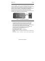
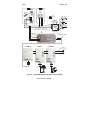
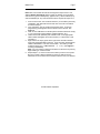
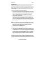
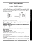
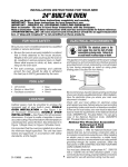
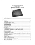
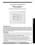
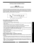
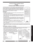
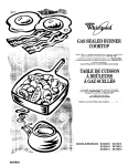
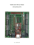
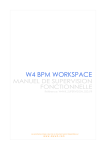
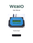
Page 1 Model IR-X10 INSTALLATION INSTRUCTIONS MODEL IR-X10 INTERFACE MODULE TABLE OF CONTENTS Section Title Page INTRODUCTION....................................................................................... 3 FEATURES AND SPECIFICATIONS ......................................................... 3 INSTALLATION......................................................................................... 5 IR-X10 SYSTEM COMMANDS .................................................................. 6 GETTING STARTED USING DRAGON DROP-IR SOFTWARE.................. 6 CHOOSING AND LISTING X10 MODULES ............................................... 7 PLACING X10 COMMANDS ON A VIRTUAL CONTROLLER ..................... 8 SCENE CONTROL.................................................................................... 9 Programming a Scene ...................................................................... 10 Scenes Setup ................................................................................... 11 Programming an X10 Scene Macro ................................................... 12 Transferring Data to a Real Controller ............................................... 13 Page 2 Model IR-X10 © 2002 Xantech Corporation. Model IR-X10 Page 3 INTRODUCTION ® The IR-X10, Figure 1, serves to connect the Xantech IR bus to the X10 Power Line Interface (PL513, PSC05, etc). Specifically, the IR-X10 converts unique IR control codes, generated by the Dragon Drop-IR software program, into X10 commands. This permits the unique lighting and control functions of the X10 system to be easily integrated into Xantech IR controlled whole-house AV systems. Refer to the Dragon Drop-IR Installation and Programming Instructions and the X10 User Manuals when planning overall configuration and operational details. X10 RJ11 Output Port Figure 1 – The IR-X10 Interface Module FEATURES AND SPECIFICATIONS • • • • • • • • • Converts specific Dragon Drop-IR code into X10 control signals IR signal & power inputs - plug-in screw-type terminals for fourconductor connections handles wire sizes from 24 to 12 gauge Opto-coupled IR IN and separate IR Gnd permits IR input to be isolated from chassis and power supply grounds, where needed IR IN accepts Xantech IR bus output from any of the Xantech IR receivers, keypads, connecting blocks, controllers, etc. X10 output jack – RJ11 modular connector RJ11-to-RJ11 cable included Power requirements – 12 VDC ± 1.5V @ 25mA Mounting – flanges, plus supplied screws permit easy mounting to flat surfaces Dimensions – 4-3/8” L x 1-7/8” W x 1-1/8” H (111mm x 48mm x 29mm) © 2002 Xantech Corporation. Page 4 Model IR-X10 ROOM 2 ROOM 1 780-10 J-Box IR Receiver GND +12V IR OUT GND GND +12 VDC IR OUT IR OUT 780-10 +12V Smart Pad J-BOX RECEIVER Hand Held Remote 782-00 Power Supply Satellite Receiver To 120 V AC (unswitched) 283M Emitter 789-44 VCR Connecting Block STATUS IR IN ® IR RCVR X10 283M Blink IR 4-Conductor Cable (RJ11 to RJ11, included) White Striped Side + Power Line Interface Emitter AV Receiver EMITTERS 789-44 GND Mono Mini-Plug to Stripped Ends, 2-Conductor Cable (part no. 06015900, not included) CONNECTING BLOCK 12VDC 283M +12 VDC X10 Lamp Module X10 Appliance Module To Additional Modules as Needed Power Line Control Link Lamp Module Appliance Module Figure 2 – Typical Multi-Room System Using the IR-X10 © 2002 Xantech Corporation. Model IR-X10 Page 5 INSTALLATION Figure 2 is a typical multi-room installation where X10 control is part of the system. A mixture of Xantech SmartPad3 keypads and IR receivers are the source of the IR control signals for both the AV products and X10. The systems is configured as follows: Note: Refer to your X10 manual for proper system configuration of X10 components. 1. Using 2-conductor cable (22AWG up to 600’, 20AWG up to 2000’ and 18AWG up to 5000’), connect PWR GND, and +12VDC connections from the IR-X10 module to the appropriate terminals on the connecting block. 2. Using a Mono Mini-Plug to Stripped Ends 2-Conductor cable (Xantech PN#06015900, not included), plug the Mini-Plug end into an available Emitter out on the Connector Block and wire the ‘Stripped End' in IR IN (White Stripe) and IR GND on the IR-X10. Note: If using Emitter Out is not practical, in Step #1 use 3Conductor (22AWG up to 600’, 20AWG up to 2000’ and 18AWG up to 5000’) to connect IR IN, PWR GND, and +12VDC connections from the IR-X10 module to the appropriate terminals on the connecting block. You must also connect a jumper wire from IR GND to PWR GND on the IR-X10. 3. Connect one end of the furnished RJ11 cable to the output port of the IR-X10 module and connect the other end into the X10 Power Line Interface (not included). 4. Plug the X10 Power Line Interface into an un-switched AC Line outlet. 5. The Dragon Drop-IR software is used to program learning remotes (used with the IR receivers), in addition to the SmartPads, with the IRX10 control commands. Note: The Xantech RC68+ (or RC68) Programmer Remote cannot be used to program IR-X10 commands! Use of Dragon Drop-IR is explained in the next section. © 2002 Xantech Corporation. Page 6 Model IR-X10 IR-X10 SYSTEM COMMANDS The IR-X10 module permits the generation of unique IR commands for the control of lighting and appliance products in X10 systems. It allows you to place such commands on any Xantech Dragon Drop-IR friendly remote or keypad controller (including: URC-2, SmartPad2, SmartPad3, Waterpad, MAC1, 590-10 and RS232IR). These commands can be placed on any key of the controller, which you later direct at a Xantech IR Receiver in an IR controlled system. The IR signal from the IR receiver must then be passed to the Xantech IR-X10 Interface Module, which converts the unique IR commands to X10 power-line carrier control signals. The IR-X10 then connects to an X10 Power Line Interface. Note: Refer to the Xantech IR-X10 Installation Instructions and the X10 User Manuals when planning overall configuration and operational details. To create IR-X10 control code using Dragon Drop-IR software, proceed as follows: GETTING STARTED USING DRAGON DROP-IR™ SOFTWARE Note: For additional reference regarding Dragon Drop-IR software, please refer to the Dragon Drop-IR manual. 1. 2. 3. 4. Start the Dragon Drop-IR Software via the Icon on your desktop or, from the START menu, choose Programs and select Drag[your version #] and click on the Dragon Drop-IR icon. From the File Menu, click New Project (CTL+N) to create a new project. (To add IR-X10 commands to an existing project, click Open Project (CTL+O) and select the project to be edited). For existing projects, go To Step 4. In the New Project window, type a file name such as joneshome1 and click OK. The proper file extension is added automatically. If the controller to be programmed (i.e. URC-2P or other) is not displayed in the Project window, click on the Base Unit menu and select the desired version of the controller you wish to program. If you are not sure of the unit, connect the unit to the serial port (refer to Dragon DropIR manual for proper connection instructions) and click “Who Am I”. A pop-up window will appear displaying the proper version # of controller. Note: For clarity of instructions, we will use the URC-2P/B as a programming example. © 2002 Xantech Corporation. Model IR-X10 Page 7 CHOOSING AND LISTING X10 MODULES Note: Each X10 module will need to be assigned a unique House / Unit Address. Before proceeding please confirm the settings on the modules and note the Type of module (Lamp, Appliance etc.), House Address (A-P), and Unit Address (#1-16). This information will be required for steps 3 & 4. 1. 2. 3. 4. 5. 6. From the X10 menu, click Create IR-X10 File. (To work with a previously created file, click Select IR-X10 File and click on the file to be edited. Proceed to Step 3). Type a filename, such as joneshmx10 and click Save. An IR-X10 programming panel appears with the filename in the title bar. See Figure 3). Click on an X10 Module from the drop down list that matches the one(s) in your X10 system (Lamp Module, Appliance Module, etc.). Under House Add. (Address) and Unit Add. Click on the appropriate letter/number that applies for the first module (i.e. House Add. A and Unit Add. 1) Right-Click in the empty space to the right of the Unit Add. selection area under the Module Name List Box. A pop-up button should appear labeled “Add Module”. Left-click on this button. This adds your first module to the list (e.g., LAMP MODULE A 1, etc.). (See Figure 3 Creating X10 Modules) Note: You can rename or delete the module from the list at any time by Right-Clicking on a listed module. Repeat steps 3, 4, and 5 for each X10 module you have in the system. Be sure to select a different address for each one and be sure the addresses set on the actual X10 modules match the ones you selected. © 2002 Xantech Corporation. Page 8 Model IR-X10 Figure 3 – Creating X10 Modules PLACING X10 COMMANDS ON A VIRTUAL CONTROLLER 1. 2. 3. 4. 5. Select the module in the Module Name List Box you would like to place on the Remote Controller by clicking once on the Module Name. The module should now be highlighted. Select a command Function from the Function List (i.e., On, On/Off Toggle, etc.) that you desire. CAUTION: The On/Off Toggle and All Lights On/Off Toggle commands will only work with the newer URC-2P/B remote and the MRC44. If you do not know which unit you have, use the “Who Am I” function under the Base Unit menu. Click a Source button on the virtual controller (URC-2P/B shown as example) where you want the command to be placed under (i.e. TV, SAT, AUX etc…). A blue outline will appear around the button and the “virtual” LED will turn red. Click a button on the virtual controller where you want the command (e.g. ‘D’). This button will now have a blue outline around it. Click Place. The command will appear in the command list (e.g., A2 On (XANTECH - IRX10). © 2002 Xantech Corporation. Model IR-X10 6. Page 9 The X10 function command is now programmed under button D of the AUX Source Bank on the virtual controller. Repeat this procedure for each module you have in the Module Name list. Refer to Figure 4 Placing X10 Commands on Controller. Figure 4 – Placing X10 Commands on Controller In this case, the X10 command for Lamp Module A2 ‘ON’ was placed on button ‘D’ under the AUX Source Bank. SCENE CONTROL The X10 Scene Control feature can also be implemented using Dragon Drop-IR software. For instance, you can create "scenes" that, with one button press, can cause several X10 Modules to set lighting to predetermined levels along with controlling other functions in the A/V system if so desired. First you need to program a Scene. © 2002 Xantech Corporation. Page 10 Model IR-X10 PROGRAMMING A SCENE 1. Right-Click in the empty space under Scene Module Level to the right of the Function List Box. A pop-up window should appear with the choices Add Light/Appliance Scene and Add Shutter Scene. 2. Select the scene for the module being controlled by left-clicking on the appropriate choice. You should now see confirmation of this choice in the Scene Module Window. For example, clicking on Add Light/Appliance Scene will post (A-1) L/A Scene. (A-1) stands for House Address A, Scene #1. 3. Click and Drag a Module from the Module Name List Box above and ‘drop it’ just below the scene line you just added. Drag and Drop as many of the X10 modules you wish to control. Refer to Figure 5. 4. Left click on each of the modules in the Scene Module Window, one at a time and adjust the Scene Module Level via the slide bar at the top of the window until the desired percentage of brightness is achieved. 5. Repeat step 4 for each module in the scene 6. The Scene is now ready for placement within a macro on the URC2P/B. Figure 5 – Programming a Scene © 2002 Xantech Corporation. Model IR-X10 Page 11 SCENES SETUP Before scenes can take effect when executed, a special Scene Setup set of codes must be issued first. This instructs each X10 module (an X10 requirement) to accept the Scene Module Level settings when sent later in a Macro. This only needs to be sent the first time being used or any time any of the X10 modules have been disconnected from the AC source or after Power Outages. There are two methods of issuing these commands. 1. Place the Scene Setup command on a dedicated button on the remote. When used for the first time or after power outages of any sort, select this button to issue the scene command and then continue to select any Macro containing a Scene Cmd (Scene Cmd explained in the next section). If a dedicated button is not available (all commands on controller used), use method #2. 2. Place the Scene Setup into a Macro following a ‘preferred’ Scene Cmd . This will save a button from only being used in Power Outages and place the Scene Cmd into a frequently used X10 Scene Macro. First time used, or after power outages, select this button twice (once to issue Scene Setup and second time will execute the desired Scene Cmd.) Method 2 will be described in the Programming an X10 Scene Macro section, Step #5. Note: You can also program a Scene Setup into Tier 2 of your controller. This way, after a Power Failure or first time use, Push & Hold the Tier 2 programmed button for more than 1 second to issue the Scene Setup. Please see your Dragon Drop-IR manual for further information regarding programming Tiered functions. Creating a Scene Setup via Method One: 1. Click Scenes Setup from the Function List Box. 2. Click a button on the URC-2P/B not used for any other function in your IR controlled system (e.g., the D button in the lower section of the URC2P/B remote). 3. Click Place from the Function section. A special set of commands will be placed under the selected URC-2P/B button. Option: To make this button accessible under any Source Bank, right-click this URC-2P/B button and then left click Punch. CAUTION: Every time you make a change in Scene Programming, you must perform a new Scenes Setup procedure by repeating steps 1 through 3. Be sure to delete the old command set before placing the new one on the controller. © 2002 Xantech Corporation. Page 12 Model IR-X10 PROGRAMMING AN X10 SCENE MACRO Creating a Scene Setup is the first half in creating a scene. This enables the X10 module to accept a Scene Command. Placing a Scene Command on the Virtual Controller: 1. In the Scene Module window, select the Scene you would like placed on the virtual Controller. (Scene Cmd in the Function List Box should change to reflect the proper scene number (i.e. Scene Cmd-(A-1)) 2. Click a Source button on the virtual controller (URC-2P/B shown as example) where you want the command to be placed under (i.e. TV, SAT, AUX etc…). A blue outline will appear around the button and the “virtual” LED will turn red. 3. Click a button on the virtual controller where you want the command. This button will now also have a blue outline around it. 4. Click Place. The command will appear in the command list (e.g., Scene Cmd – (A-1) (XANTECH - IRX10)). 5. To add a Scene Setup to this Macro (Method 2 from above), select Scene Setup in the Function List Box and then click Place. You should now see the Scene Setup commands added to the Command List window. (Refer to Figure 6) Now this Macro can be used as the Scene Command to set lighting to a predetermined level and be used to reset the X10 modules after a Power Failure. You can now add other commands to this macro in the same manner and cater it to your needs. For example, you can add a Play command for your DVD player. Now any time this macro is selected, the lights will dim to a preset level and the DVD will start. The possibilities are left to the user! © 2002 Xantech Corporation. Model IR-X10 Page 13 Figure 6 – Creating a Scene Command Macro TRANSFERRING DATA TO A REAL CONTROLLER When you have completed all programming of the virtual keypad and tested all commands to see that they operate the Controlled Equipment, you are then ready to do a Project Download that will transfer all data to a "real" controller (URC-2P/B in this example). Note: Testing X10 commands on a Virtual URC can sometimes be intermittent but when program is transferred to remote, all works fine. During Test Mode, the URC-2 will only emit ONE code burst. In normal use through a URC-2, the whole time a button is pressed, consecutive commands are transmitted. To simulate this, version 2.00 software or higher, has a REPEAT function. Add a REPEAT of ‘1’ or ‘2’ just before the command. This will not affect the button function in any way and will make the Test mode more accurate. © 2002 Xantech Corporation. Page 14 Model IR-X10 Proceed as follows: 1. Be sure the URC-2P/B (or other applicable Controller) is connected to the computer (refer to Dragon Drop-IR Software instructions for proper connection to PC). 2. From the File menu, select Base Unit Transfer (Ctrl+B). A Project Down Load window appears with the statement "Synching Please Wait", then "Transmitting Please Wait". 3. A transfer status bar is shown as the transmission of data progresses. See Figure 7. Also, the Status LED on the URC-2P/B blinks orange and green until the transfer completes. 4. The newly programmed unit should now operate all the IR-controlled equipment in your system. 5. Using the same procedure, you may transfer to any number of additional Controllers. Figure 7 – Transferring Data to a Real Controller © 2002 Xantech Corporation. Model IR-X10 Page 15 © 2002 Xantech Corporation. X10 is a registered trademark of X10 Ltd Corporation Bermuda, Hong Kong XANTECH CORPORATION 12950 Bradley Avenue, Sylmar CA 91342-3829 phone 818.362.0353 • fax 818.362.9506 www.xantech.com Part No. 08904870 Rev A 06-26-2002