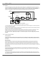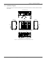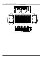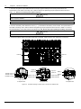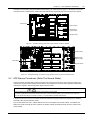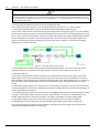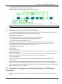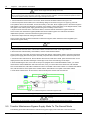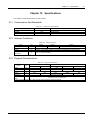
1
Liebert NXL UPS Single And "1+N" Parallel System 500/600/800kVA User Manual Version V1.6 Revision date BOM June 24, 2011 31012213 Emerson Network Power provides customers with technical support. Users may contact the nearest Emerson local sales office or service center. Copyright © 2009 by Emerson Network Power Co., Ltd. All rights reserved. The contents in this document are subject to change without notice. Emerson Network Power Co., Ltd. Address: No.1 Kefa Rd., Science & Industry Park, Nanshan District 518057, Shenzhen China Homepage: www.emersonnetworkpower.com.cn E-mail: [email protected] Important Notice This manual involves the relevant installation and operation documents of Liebert NXL 500/600/800kVA UPS single module and “1+N parallel system”. Please read carefully the relevant chapters of this manual before installation. The UPS must be commissioned by the engineer designated by the manufacturer or its agent before it can be used. Otherwise, the UPS damage caused will not be covered by the warranty. The Liebert NXL 500/600/800kVA UPS is used only for commercial and industrial purpose, and shall not be used as the power supply for life support equipment. This Manual Covers The Following Parts: Equipment 500kVA UPS (12-pulse) 600kVA UPS (12-pulse) 800kVA UPS (12-pulse) Options 500kVA trap filter (50Hz) 600kVA trap filter (50Hz) 800kVA trap filter (50Hz) Bypass current sharing inductor Surge protection device (Level D) BCB box BCB cabinet Common BCB box Common BCB cabinet SIC card Modbus card Battery temperature sensor Battery ground fault device Input contact isolator (ICI) boards Programmable relay board (PRB) Seismic anchor kit Model Liebert NXL 500kVA Liebert NXL 600kVA Liebert NXL 800kVA Model UF-BCB-NXL 500kVA UF-BCB-NXL 800kVA UF-BCB-NXL-COMM NXL-BCB-COMM-B UF-SNMP810 UF-MODBUS310 UF-BTS-NXL UF-BGFD-NXL UF-ICI-NXL UF-PRB-NXL Safety Precautions Compliance 警告 危and 险 standards This equipment complies with the following UPS reference standards: IEC60950-1, IEC62040-1 general safety requirements of UPS IEC/EN62040-2 EMC requirements IEC62040-3 performance requirements and test methods The equipment installation shall comply with the above requirements and use the accessories specified by the manufacturer. 警告Warning 危险 Large ground leakage current: before getting access to input power (including AC mains and batteries), the grounding must be reliable. Equipment grounding must comply with local electric regulations. 警告Warning 危险 The selection of the prestage distribution protection equipment of the UPS system must comply with the local electric regulations. 警告Warning 危险 When the internal fuse of the UPS is damaged, it must be replaced with fuse of the same electric parameters by professionals. 警告Caution 危险 This equipment is installed with EMC filter. The ground leakage current is 3.5mA~3000mA. When selecting the RCCB or other RCD, the transient state and steady state ground leakage current upon equipment startup shall be taken into consideration. RCCB which is sensitive to unidirectional DC pulse (class A) and insensitive to transient state current pulse must be selected. Pay attention that the load to ground leakage current will also pass the RCCB or RCD. 警告Warning 危险 This system provides control signal to be used together with the external automatic circuit breaker, so as to prevent the inverter voltage from feeding back to the input side through bypass static switch. If this protection function is not used together with the switch equipment for isolating the bypass circuit, the switch equipment must be labeled to alert the maintenance personnel that this circuit is connected with the UPS system. The text of the label has or is equivalent to the following meaning: risk of voltage backfeed. Before working on this circuit, please isolate the UPS and check all terminals (including the protective earth) for hazardous voltage. 警告Warning 危险 When this product is used for the commercial and industrial purposes in the environment of category 2, suppression device or additional measures shall be applied to suppress the interference. 警告General 危 险safety precautions Like other types of large power equipment, the UPS and battery box have high voltage inside. Because the components with high voltage can be accessed only when the front door (which is locked) is opened, the risk of contacting high voltage has been minimized. This equipment meets the IP20 standard, and other safety shields are provided inside the equipment. There will not be any danger when operating this equipment according to the general instructions and the steps recommended in this manual. All the equipment maintenances involve the contact with the internal parts, and such operations shall be conducted by the properly training personnel. 警告Battery 危险 The battery manufacturer has provided the precautions that should be complied with when using the large batteries or near the batteries. Such precautions must be complied with at any time. The relevant suggestions on the local environment conditions and the regulations on providing PPE, first aid equipment and fire fighting equipment shall be paid special attention to. 警告 危 险 This warning mark represents all the indications for human safety. Contents Chapter 1 Overview ............................................................................................................................................................ 1 1.1 Features ................................................................................................................................................................ 1 1.2 Design Concept .................................................................................................................................................... 1 1.2.1 System Design .......................................................................................................................................... 1 1.2.2 Bypass ....................................................................................................................................................... 2 1.2.3 System Control Principle ........................................................................................................................... 2 1.2.4 UPS Power Supply Switch Configuration .................................................................................................. 3 1.2.5 Battery Circuit Breaker............................................................................................................................... 3 1.2.6 Battery Temperature Compensation .......................................................................................................... 3 1.3 Modes Of Operation.............................................................................................................................................. 3 Chapter 2 Mechanical Installation ....................................................................................................................................... 5 2.1 Precautions ........................................................................................................................................................... 5 2.2 Environmental Requirement ................................................................................................................................. 5 2.2.1 UPS Location Selection ............................................................................................................................. 5 2.2.2 Battery Location Selection ......................................................................................................................... 6 2.3 Mechanical Requirement ...................................................................................................................................... 6 2.3.1 System Composition .................................................................................................................................. 6 2.3.2 Movement Of Cabinet ................................................................................................................................ 6 2.3.3 Operation Space ........................................................................................................................................ 6 2.3.4 Removing Transportation Rubber Strip And Fixing Device........................................................................ 6 2.3.5 Cable Access Mode ................................................................................................................................... 7 2.3.6 Mechanical Connection Between The Cabinets ........................................................................................ 7 2.4 Initial inspection .................................................................................................................................................... 8 2.5 Installation Diagram .............................................................................................................................................. 9 Chapter 3 Electrical Installation ......................................................................................................................................... 11 3.1 Wiring Of Power Cable ....................................................................................................................................... 11 3.1.1 System Configuration .............................................................................................................................. 11 3.1.2 Cable Specification .................................................................................................................................. 11 3.1.3 Notes ....................................................................................................................................................... 12 3.1.4 Battery Connecting Terminal ................................................................................................................... 12 3.1.5 Protection Ground ................................................................................................................................... 12 3.1.6 Protection Device .................................................................................................................................... 12 3.1.7 Power Cable Connection Steps ............................................................................................................... 13 3.2 Distance Between The UPS Connection Point And The Floor ............................................................................ 15 3.3 Wiring Of Control Cable ...................................................................................................................................... 15 3.3.1 Overview.................................................................................................................................................. 15 3.3.2 Input Dry Contact Interface ...................................................................................................................... 16 3.3.3 Output Dry Contact Interface ................................................................................................................... 18 3.3.4 EPO Input Interface ................................................................................................................................. 19 3.3.5 Battery Circuit Breaker Interface .............................................................................................................. 20 3.3.6 Interface TB1101 ..................................................................................................................................... 21 3.3.7 Cable Entry And Routing ......................................................................................................................... 21 3.4 Electrical Connection Between The Cabinets ..................................................................................................... 27 3.4.1 Power Connection ................................................................................................................................... 27 3.4.2 Signal Connection ................................................................................................................................... 31 Chapter 4 Operator Control And Display Panel ................................................................................................................. 34 4.1 Introduction ......................................................................................................................................................... 34 4.2 Types Of LCD Screen ......................................................................................................................................... 35 4.2.1 Startup Screen......................................................................................................................................... 35 4.2.2 Main Display Screen ................................................................................................................................ 36 4.3 Power Flow Diagram ........................................................................................................................................... 38 4.3.1 Overview.................................................................................................................................................. 38 4.3.2 Power Flow Diagram In Normal Mode ..................................................................................................... 39 4.3.3 Power Flow Diagram In Bypass Mode ..................................................................................................... 39 4.3.4 Power Flow Diagram In Battery Mode ..................................................................................................... 39 4.3.5 Power Flow Diagram In Maintenance Bypass Mode ............................................................................... 40 4.4 Detailed Menu ..................................................................................................................................................... 40 4.4.1 Configuration ........................................................................................................................................... 41 4.4.2 Status Report........................................................................................................................................... 46 4.4.3 Startup ..................................................................................................................................................... 46 4.4.4 Shutdown................................................................................................................................................. 46 4.4.5 Transfer ................................................................................................................................................... 47 4.4.6 Battery Management ............................................................................................................................... 48 4.4.7 Metering................................................................................................................................................... 50 4.4.8 Help ......................................................................................................................................................... 50 4.4.9 Reset ....................................................................................................................................................... 50 4.4.10 Silence ................................................................................................................................................... 50 4.5 EPO Button ......................................................................................................................................................... 50 4.6 UPS Event Record List ....................................................................................................................................... 51 Chapter 5 UPS Operation Introduction .............................................................................................................................. 58 5.1 Brief Introduction ................................................................................................................................................. 58 5.1.1 Precautions.............................................................................................................................................. 58 5.1.2 Power Supply Switch ............................................................................................................................... 58 5.2 UPS Startup Procedures (Enter The Normal Mode) ........................................................................................... 59 5.3 Operating Procedures Of Testing The Battery .................................................................................................... 61 5.4 Procedures For Operating From Maintenance Bypass (UPS Shutdown Procedures) ........................................ 61 5.5 Transfer Maintenance Bypass Supply Mode To The Normal Mode .................................................................... 62 5.6 Shutdown Procedures (Shut Down UPS And The Load Completely) ................................................................. 63 5.7 Emergency Power Off (EPO) Procedures ........................................................................................................... 64 5.8 UPS Reset Procedures After EPO ...................................................................................................................... 64 5.9 Automatic Restart ............................................................................................................................................... 64 5.10 Language Selection .......................................................................................................................................... 65 5.11 Change The Current Date And Time ................................................................................................................ 65 5.12 Change Password............................................................................................................................................. 65 Chapter 6 Battery .............................................................................................................................................................. 67 6.1 Introduction ......................................................................................................................................................... 67 6.2 Safety.................................................................................................................................................................. 67 6.3 UPS Battery ........................................................................................................................................................ 68 6.4 Precautions For Installation Design .................................................................................................................... 69 6.5 Battery Installation Environment And Number Of Batteries ................................................................................ 69 6.5.1 Installation Environment: ......................................................................................................................... 69 6.5.2 Number Of Batteries ................................................................................................................................ 70 6.6 Battery Protection ............................................................................................................................................... 70 6.7 Battery Connection ............................................................................................................................................. 71 6.7.1 Battery Assembly ..................................................................................................................................... 71 6.7.2 Battery Wiring .......................................................................................................................................... 71 6.8 Battery Installation .............................................................................................................................................. 71 6.9 BCB Box (Cabinet) (Option) ................................................................................................................................ 72 6.10 Battery Temperature Sensor (Option) ............................................................................................................... 72 6.11 Battery Maintenance ......................................................................................................................................... 72 6.12 Battery Recycling .............................................................................................................................................. 72 Chapter 7 1+N Parallel System Installation ....................................................................................................................... 74 7.1 Configuration....................................................................................................................................................... 74 7.1.1 Overview.................................................................................................................................................. 74 7.1.2 External Protection Device ...................................................................................................................... 75 7.1.3 Cabinet Installation .................................................................................................................................. 75 7.1.4 Power Cable ............................................................................................................................................ 75 7.1.5 Inter-Module Communications (IMC) Board ............................................................................................ 76 7.1.6 Control Cable........................................................................................................................................... 77 7.1.7 Remote Emergency Shutdown ................................................................................................................ 78 7.1.8 External Switch ........................................................................................................................................ 78 7.2 Operation Steps For “1+N” Parallel System ........................................................................................................ 79 7.2.1 Startup Steps ........................................................................................................................................... 79 7.2.2 Shutdown Steps (Complete Shutdown Of All The UPS And Load) ......................................................... 84 7.2.3 Operation Steps Of Transferring From The UPS To The Shared Maintenance Bypass .......................... 86 7.2.4 Transfer Maintenance Bypass Supply Mode To The Normal Mode ........................................................ 86 7.3 Dual-Bus System ................................................................................................................................................ 87 7.3.1 External Protection Device ...................................................................................................................... 87 7.3.2 Cabinet Installation .................................................................................................................................. 87 7.3.3 Power Cable ............................................................................................................................................ 88 7.3.4 Cable Control........................................................................................................................................... 88 Chapter 8 Communication................................................................................................................................................. 90 8.1 SNMP Protocol Communication.......................................................................................................................... 90 8.2 Modbus Protocol Communication ....................................................................................................................... 90 8.2.1 Communication Through Modbus Card ................................................................................................... 91 8.2.2 Communication Through HMI Control Board ........................................................................................... 92 8.3 Dry Contact Communication ............................................................................................................................... 93 8.3.1 Communication Through ICI Board And PRB.......................................................................................... 94 8.3.2 Communication Through EIB................................................................................................................... 94 Chapter 9 Maintenance ..................................................................................................................................................... 95 9.1 Safety.................................................................................................................................................................. 95 9.2 Key Components And Service Life Of UPS ........................................................................................................ 95 9.2.1 Magnetic Components: Transformers, Inductors ..................................................................................... 95 9.2.2 Power Semiconductor Devices ................................................................................................................ 95 9.2.3 Electrolytic Capacitor ............................................................................................................................... 95 9.2.4 AC Capacitor ........................................................................................................................................... 95 9.2.5 Air Filter ................................................................................................................................................... 96 9.2.6 Life Parameters And The Proposed Replacement Time Of Key Components ........................................ 96 9.2.7 The Replacement Of Fuse....................................................................................................................... 96 9.3 The Maintenance Of UPS And Options .............................................................................................................. 96 Chapter 10 Specifications ................................................................................................................................................. 97 10.1 Conformance And Standards ............................................................................................................................ 97 10.2 Ambient Conditions ........................................................................................................................................... 97 10.3 Physical Characteristics .................................................................................................................................... 97 10.4 UPS Electric Characteristics (Rectifier) ............................................................................................................. 98 10.5 UPS Electric Characteristics (DC Intermediate Circuit) ..................................................................................... 99 10.6 UPS Electric Characteristics (Inverter Output) .................................................................................................. 99 10.7 UPS Electric Characteristics (Bypass Input) ................................................................................................... 100 Appendix 1 Guidance For Removing Transport Fixtures................................................................................................. 101 1. Procedures For Removing 500kVA UPS Transport Fixtures .............................................................................. 101 1.1 Procedures For Removing The Fixed Screws Of The Rectifier Input Transformer ................................... 101 1.2 Procedures For Removing The Fixed Screws Of The Output Transformer In Inverter Cabinet ................ 102 2. Procedures For Removing 600kVA /800kVA UPS Transportation Restraint ...................................................... 103 2.1 Procedures For Removing The Fixed Screws Of The Rectifier Cabinet Input Transformer ..................... 103 2.2 Procedures For Removing The Fixed Screws Of The Inverter Cabinet Output Transformer .................... 104 Chapter 1 Overview 1 Chapter 1 Overview This chapter briefly introduces the features, design concepts and operating modes of Liebert NXL 500/600/800kVA UPS (hereinafter referred to as UPS). 1.1 Features The UPS is connected between the three-phase input power and the critical loads (e.g. computer) to provide high quality three-phase power for the loads. The UPS has the following advantages: Increase the power supply quality The UPS protects its output against the input power change through the internal voltage and frequency controller. Improve noise suppression Due to the application of AC-DC-AC conversion mode, the noise in the input power is effectively filtered, and the load gets clean power supply. Provide mains failure protection If the input power fails, the UPS will work in battery mode, and the power supply to the loads will not be interrupted. 1.2 Design Concept 1.2.1 System Design This section introduces the working principle of the UPS Single Module. The UPS adopts AC-DC-AC converter (as shown in Figure 1-1)The first stage conversion (AC-DC) adopts three-phase full bridge rectifier that uses SCR to convert the three-phase input voltage to stable DC bus voltage. Bypass AC supply Inverter Rectifier Static switch UPS AC output Rectifier AC supply Battery Figure 1-1 Block diagram for working principle of single module The rectifier also has the function of charger. It adopts advanced temperature compensation technology to effectively prolong the battery service life. The inverter mainly adopts large power Insulated Gate Bipolar Transistor (IGBT), and adopts advanced space vector pulse width modulation (SVPWM) technology for control, to invert the DC bus voltage back to AC voltage. When the mains is normal, the rectifier and inverter work together to supply the loads and charge the battery. When the mains is abnormal, the rectifier stops working, and the battery provides power to the loads through the inverter. If the battery voltage falls to end of discharge (EOD) voltage and the mains still has not been recovered, the UPS will shut down (if the bypass is normal, the system will transfer to bypass). The battery EOD voltage is preset. The time when the mains is abnormal and the battery maintains the UPS operation till the battery voltage is reduced to EOD voltage and the UPS shuts down is called backup time. The length of backup time depends on the battery capacity and the loads. Liebert NXL UPS Single And "1+N" Parallel System 500/600/800kVA User Manual 2 Chapter 1 Overview 1.2.2 Bypass Through the intelligent control of the static switch module containing the controllable electronic switch (as shown in Figure 1-2), the loads can be supplied by the inverter or the bypass. In normal situation, the loads are supplied by the inverter, in which case the static switch at inverter side is closed. In the case of overload (the overload delay time expires) or inverter failure, the static switch module will automatically transfer the loads to the bypass. Bypass mains supply Maintenance bypass switch Q3 UPS Bypass switch Q2 Rectifier Input mains supply Inverter Static switch DC bus Input switch Q1 Output switch Q4 UPS output C.B. Battery Battery circuit breaker Figure 1-2 UPS power supply switch configuration In normal operating state, to realize the uninterrupted transfer between inverter and bypass , the inverter output must be synchronized with the bypass. Therefore, when the bypass frequency is within the synchronization range, the inverter control circuit will synchronize the inverter output frequency with the bypass frequency. Besides, the UPS has a manual maintenance bypass switch for the shutdown of the UPS for maintenance. In this situation, the bypass will directly supply the critical loads through the manual maintenance bypass switch. Note: When the load is supplied by the bypass or maintenance bypass, the power supply quality cannot be ensured. 1.2.3 System Control Principle Normal operation Normal mode: It means that the UPS has normal input mains, the rectifier and inverter operate normally, the load is supplied by the inverter, the battery circuit breaker is closed, and the battery is in stable floating charge state with DC bus voltage. Mains abnormal When the mains fails or is abnormal, the rectifier will stop working automatically, and the system will transfer to battery output (through inverter). The length of the operation time in battery mode depends on the load and the battery capacity. During this period, if the battery voltage falls to the EOD voltage and the mains still has not been recovered, the inverter will stop working automatically, and the UPS operation control panel will display corresponding alarm message. Mains recovery When the mains resumes normal within allowable time, the rectifier will start automatically (at this time its output power will increase gradually) and supply the load and charge the battery again. Therefore, the power supply to the load will not be interrupted. Battery disconnection To disconnect the battery from the UPS system for maintenance, the external isolating switch can be used. At this time, except for the mains failure battery backup function, other functions and all the steady state performance of the UPS will not be affected. Liebert NXL UPS Single And "1+N" Parallel System 500/600/800kVA User Manual Chapter 1 Overview 3 UPS Single Module failure In case of inverter failure, the load will be automatically transferred to the bypass, and the output power supply will not be interrupted. In this situation, please contact the local customer service center of Emerson Network Power Co., Ltd for technical support. Overload If the inverter is overloaded or the inverter current remains outside the specifications (refer to Table 9-6) longer than the specified time, the load will be automatically transferred to the bypass without power interruption. If both the overload and the current are reduced to a level within the specified range, then the load will be transferred back to the inverter. In case of output short circuit, the load will be transferred to the bypass, and the inverter will shut down. One minute later, the inverter will start up automatically. If at this point the short circuit is removed, the load will be transferred back to the inverter. The transfer is determined first of all by the features of the protection device of the system. In the above two situations, the UPS operation control panel will display alarm message. Maintenance bypass The UPS has a second bypass circuit, i.e. maintenance bypass, which provides a safe working environment for the engineers to provide regular maintenance or repair to the UPS system and at the same time provide unregulated mains supply to the loads. The maintenance bypass can be manually selected through the maintenance bypass switch. It can be disconnected by turning the switch to OFF. 警告Warning 危险 If the UPS system is composed of more than 2 parallel UPS modules, do not use the internal maintenance bypass switch. Caution: If the input distribution does not have automatic circuit breaker, the output bus and the input bus of the UPS module that has shut down may have dangerous high voltage. 1.2.4 UPS Power Supply Switch Configuration Figure 1-2 describes the block diagram of the UPS Single Module that has split bypass power supply (that is, the bypass adopts independent mains input). In the split bypass, the static bypass and maintenance bypass share the same independent bypass power supply. During the normal operation of the UPS, except for the maintenance bypass switch Q3, all the other switches shall be closed. 1.2.5 Battery Circuit Breaker The battery shall connect to the DC bus through the battery circuit breaker. The battery circuit breaker is a standard option, which shall be installed near the battery. The battery circuit breaker is closed manually or electrically. The battery circuit breaker has undervoltage tripping coil. Upon the DC bus undervoltage, the UPS control circuit will send a signal to the coil to trip the battery circuit breaker. 1.2.6 Battery Temperature Compensation The UPS system has battery charge temperature compensation function. When the ambient temperature is increased, the DC bus voltage (which charges the battery) will be reduced correspondingly, so as to provide optimal charging voltage to the battery. The function must be used together with the battery temperature detection device. The battery temperature sensor is a standard option for battery temperature detection. 1.3 Modes Of Operation The UPS can be in one of the following operation modes: Normal mode The mains is rectified by the UPS rectifier and then inverted by the inverter to provide uninterrupted AC power supply to the loads. At the same time, the charger (i.e., the rectifier) will float or perform equalization charging to the battery. Liebert NXL UPS Single And "1+N" Parallel System 500/600/800kVA User Manual 4 Chapter 1 Overview Note: When the mains power comes from a generator, it is required to configure dry contact signals for the generator. For details, see 3.3.2 Input Dry Contact Interface. If dry contact signals cannot be configured for the generator, please make sure that the trap filter is open; if the trap filter is closed, please open it manually. For detailed procedures, see 4.4.4 Shutdown. Battery mode The operation mode in which the battery provides backup power supply to the loads through the inverter is called battery mode. Upon mains failure, the system will automatically transfer to the battery mode, and the power supply to the load will not be interrupted. When the mains is recovered, the system will automatically transfer back to the normal mode without any manual intervention, and the power supply to the load will not be interrupted. Automatic restart mode The UPS has automatic restart function. When the inverter shuts down because the mains fails and the battery discharges to EOD voltage, if the mains is recovered, the UPS will restart automatically after a certain time of delay. This function and the automatic restart type can be set by the commissioning engineer authorized by Emerson. Bypass mode The load is powered by the static bypass mains. This power supply mode can be considered as an intermediate power supply mode when the load transfers between the inverter and the maintenance bypass, or a power supply mode for abnormal working state. Maintenance bypass mode The UPS shuts down, and the load connects directly to the bypass power supply through the maintenance bypass switch. Joint power supply mode The UPS provides joint power supply mode to use the AC mains input power in a restricted pattern and at the same time fully meet the power supply requirement of the load. If the mains is insufficient to supply the load, the insufficiency can be supplemented by the battery. This function is suitable for the application where higher rate is charged for peak hours or there are not enough diesel generators to meet the power supply requirement of the load upon mains failure. Liebert NXL UPS Single And "1+N" Parallel System 500/600/800kVA User Manual Chapter 2 Mechanical Installation 5 Chapter 2 Mechanical Installation This chapter briefly introduces the mechanical installation of the UPS, including the precautions, environmental requirement, mechanical requirement, initial inspection before installation and installation diagram. 2.1 Precautions 警告Warning 危险 Before the arrival of the authorized engineer, do not power on the UPS. 警告Warning 危险 The UPS installation shall be carried out by qualified engineer according to the description of this chapter. Detailed mechanical and electric installation documents will be provided for all the equipment not covered in this manual upon delivery. 警告Warning: 危 险 battery danger Special care shall be taken when installing batteries. When connecting batteries, the battery terminal voltage will reach 540VDC, which is fatal to human being. 1. Please wear safety glasses to protect the eyes from being damaged by arc. 2. Remove all the metal items, including finger rings, watch, etc. 3. Use tools with insulated handle. 4. Wear rubber gloves. 5. If the battery has electrolyte leakage or the battery is damaged, it must be replaced. Place the battery into the container that can withstand sulfuric acid and dispose of it according to the local regulations. 6. If the skin contacts the electrolyte, flush it with water immediately. Warning 警告 危险 The UPS system can connect to the power system (i.e., IT system) whose neutral point is not earthed. This chapter introduces the environmental and mechanical requirements that must be considered for location selection and wiring of the UPS. Because each site has its particular characteristics, this chapter will not introduce any detailed installation procedures. It will provide general installation procedures and methods for the reference of the installation personnel, so that they can properly handle the specific situations of the sites. 2.2 Environmental Requirement 2.2.1 UPS Location Selection The UPS shall be installed in a cool, dry, clean and well ventilated environment in which the mounting floor shall be flat and even, and the ambient environmental parameters shall be within the specified range, as shown in Table 10-2. The UPS adopts forced air convection cooling which is provided by the internal fan. The cold air enters the UPS through the grills of the UPS cabinet and exhausts through the top grill of the UPS. If the UPS is mounted on the raised floor and adopts bottom inlet mode, the cold air can enter the UPS through the gap between the UPS and the floor. Exhaust fan shall be installed when necessary to accelerate the ambient air circulation. In the dusty environment, air filter shall be installed. Note 1: When the battery cabinet is installed near the UPS, the maximum allowable ambient temperature is dependent on the battery rather than the UPS. Note 2: The UPS shall be mounted on the concrete or other incombustible surface. Liebert NXL UPS Single And "1+N" Parallel System 500/600/800kVA User Manual 6 Chapter 2 Mechanical Installation Note 3: When the UPS is in the inverter mode, there will be large power consumption. Proper air conditioning system shall be selected according to the inverter operating mode. 2.2.2 Battery Location Selection The ambient temperature is the main factor that affects the battery capacity and life. The normal operating temperature of the battery is 20°C. If the ambient temperature is higher than 20°C, the battery life will be reduced. If it is lower than 20°C, the battery capacity will be reduced. In normal situation, the allowable ambient temperature for the battery is 15°C to 25°C. The ambient temperature of the battery shall be maintained constant, and the battery shall be kept away from heat source and air outlet. Battery can be installed inside the specialized battery cabinet which shall be close to the UPS. If the battery is placed on the raised floor, bracket shall be installed under the floor, just as for the UPS. If the battery adopts rack mounting or is mounted far from the UPS with other installation mode, the battery circuit breaker shall be installed near the battery, and the cabling distance shall be minimized. The battery interface board (BIB) and battery circuit breaker (BCB) shall be placed inside the BCB box (cabinet). 2.3 Mechanical Requirement 2.3.1 System Composition The 500kVA UPS cabinet includes rectifier cabinet and inverter cabinet. The 600kVA/800kVA UPS cabinet includes rectifier cabinet, inverter cabinet and switch cabinet. All the cabinets are of the same height and installed side by side for aesthetic effect. 2.3.2 Movement Of Cabinet Warning 警告 危险 1. The lifting equipment for moving the UPS cabinet shall have enough lift capacity. 2. Vertical hanging of cabinet is not allowed. Ensure that the UPS weight does not exceed the lifting capacity of the lifting equipment. For the UPS weight, refer to Table 10-3. The UPS cabinet can be moved by fork truck. The front, rear (or side) grids at the bottom of the cabinet shall be removed. 2.3.3 Operation Space Because the UPS has no grill at the two sides and the rear side, there is no special clearance requirement on the two sides and rear side. However, when space permitting, please reserve a clearance of 600mm for operating the rear magnetic components. Enough operation space shall be reserve at the front of the UPS, ensuring that operators can pass freely when the UPS door is completely opened. 2.3.4 Removing Transportation Rubber Strip And Fixing Device To minimize the friction between the outer door and inner door of the cabinet during the transportation, rubber strip is added between the outer door and inner door at the factory before delivery. When the equipment arrives at the user’s site, the rubber strips shall be removed. Before the UPS is in position, remove the transportation fixing device for fixing the input transformer and the output transformer. For detailed operations, refer to Appendix 1 Guidance For Removing Transport Fixtures. Liebert NXL UPS Single And "1+N" Parallel System 500/600/800kVA User Manual Chapter 2 Mechanical Installation 7 2.3.5 Cable Access Mode The UPS can adopt top cable access and bottom cable access. When adopting top cable access, remove the baffle plates at the top of the rectifier cabinet and switch cabinet, and you can see the copper busbar. When adopting bottom cable access, remove the left baffle plate at the bottom of the rectifier cabinet and the right baffle plate at the bottom of the switch cabinet, and you can see the copper busbar. For bottom cable access, the cables shall enter from the rear side of the rectifier cabinet and switch cabinet. Note: When power cable is connected to the UPS from the bottom, proper cable size and cabling mode shall be selected to ensure that the cable can be connected to the UPS copper busbar smoothly. 2.3.6 Mechanical Connection Between The Cabinets The UPS is composed of several cabinets, and mechanical connections between the cabinets shall be carried out. The cabinets shall be connected firmly to prevent any displacement because of vibration and provide reliable grounding. As shown in Figure 2-1, the 500kVA UPS cabinet includes rectifier cabinet and inverter cabinet. The cabinets shall be fixed with bolts at point A and point B at the front of the cabinet as well as the two corresponding positions at the rear side of the cabinet. The four points adopt the same bolts, with 2 bolts for each point. Therefore, 8 M10×30, 8 plain washer M10 and 8 spring washer M10 are needed for the connection between the cabinets. The recommended bolt tightening torque for M10 is 35Nm. A Rectifier cabinet B Inverter cabinet Bolt M10 × 30 (2 pcs) Flat washer M10 (2 pcs) Spring washer M10 (2 pcs) A amplified view Figure 2-1 Illustration drawing for mechanical connection between the cabinets of 500kVA UPS Liebert NXL UPS Single And "1+N" Parallel System 500/600/800kVA User Manual 8 Chapter 2 Mechanical Installation As shown in Figure 2-2, the 600kVA/800kVA UPS cabinet includes rectifier cabinet, inverter cabinet and switch cabinet. The cabinets shall be fixed with bolts at point A, point B, point C and point D at the front of the cabinet. Points A, C and D adopt the same bolts, with 2 bolts for each point. Point B adopts 1 bolt. At the corresponding place at the rear side of the cabinet, there are also 4 points for fixing with bolts. Points A, B, C and D at the rear side adopt the same bolts, with 2 bolts for each point. Therefore, 15 M10×30, 15 plain washer M10 and 15 spring washer M10 are needed for the mechanical connection between the cabinets. The recommended bolt tightening torque for M10 is 35Nm. B A Rectifier cabinet 整流柜 A B C D Inverter cabinet 逆变柜 开关柜 Switch cabinet Bolt (2 pcs) 螺栓M10×30(2颗) 平垫M10(2颗) Flat washer (2 pcs) 强垫M10(2颗) 弹 Spring washer (2 pcs) A A处放大图 amplified view Figure 2-2 Illustration drawing for mechanical connection between the cabinets of 600kVA/800kVA UPS 2.4 Initial inspection Before installing the UPS, carry out the following inspections: 1. Ensure that the environment of the UPS equipment room meets the environmental requirement specified in the product technical specifications, especially the ambient temperature, ventilation conditions, and the dust situations. 2. Unpack the UPS and battery and visually inspect whether the inside and outside of the UPS and battery have any transportation damage. If there is any damage, report to the carrier immediately. Liebert NXL UPS Single And "1+N" Parallel System 500/600/800kVA User Manual Chapter 2 Mechanical Installation 2.5 Installation Diagram Figure 2-3 and Figure 2-4 respectively describes the key mechanical characteristics of 500kVA, 600kVA and 800kVA UPS cabinets. Top view (door open) 1445 1774 Right view Front view Left view 篁牦? 左牦? Air outlet 1250 3?? ? Air inlet 1585 3?? ? Air outlet Air inlet 1950 ??? ? ??? ? 1000 Removable grill panel (can be removed for lifting with fork-lift truck, and installed for protection and ventilation) 95 497 497 269 316 665 74 839 81 161 2835 UPS/顶/正/侧/底视图(单位:mm) Bottom view Figure 2-3 Top/front/side/bottom view of the 500kVA UPS (unit: mm) Liebert NXL UPS Single And "1+N" Parallel System 500/600/800kVA User Manual 9 10 Chapter 2 Mechanical Installation Top 顶视图(门开) view (door open) 1890 1890 Right 右视图view Left左视图 view Front view 正视图 Air出风口 outlet 1585 1585 1570 1570 出风口 Air outlet 800 800 进风口 Air inlet 进风口 Air inlet 1950 1950 Removable grill panel 可拆卸栅板 1090 1090 1090 Removable grill panel (can be removed for lifting with fork-lift 可拆卸栅板 truck, and installed for protection and ventilation) (卸下栅板可用于叉车搬运,安装后可用于防护通风) 整流柜 逆变柜 Rectifier cabinet Inverter cabinet 底视图 269 269 316 665 665 316 269 269 316 316 316 316 开关柜 Switch cabinet 251 251 269 269 1090 1090 294 294 935 935 3955 3955 Bottom view Figure 2-4 Top/front/side/bottom view of the 600kVA/800kVA UPS (unit: mm) Liebert NXL UPS Single And "1+N" Parallel System 500/600/800kVA User Manual Chapter 3 Electrical Installation 11 Chapter 3 Electrical Installation This chapter mainly introduces the electrical installation of the UPS, including the power cable and control cable connecting procedures and methods, distance between UPS connecting point and the ground, connection of dry contact, and the electrical connection between the cabinets. After completing the mechanical connection of the UPS, it is required to connect the power cable and control cable of the UPS. All the control cables, whether shielded or not, shall be kept away from the power cables. The metal pipe is connected to the metal part of the cabinet connecting these power cables. 3.1 Wiring Of Power Cable 警告Warning 危险 Before wiring the UPS, further confirm the position and status of the UPS main input/bypass and mains distribution switches. Ensure that these switches are in OFF state, and stick alarm label to the switches to prevent others from operating them. For cable access mode, refer to 2.3.5 Cable Access Mode. 3.1.1 System Configuration The cable size of the system power cable shall meet the following requirement: UPS input cable The cable size of the UPS input cable differs with the UPS power ratings and input AC voltages, provided that it meets the requirement of maximum input current, including the maximum battery charge current, as shown in Table 3-1. UPS bypass and output cable The cable size of the UPS bypass and output cable differs with the UPS power rating and output AC voltages, provided that it meets the requirement of nominal output or bypass current, as shown in Table 3-1. Battery cable Each UPS connects to its battery through the cables connecting to the positive and negative poles. The cable size of the battery cable differs with the UPS power ratings, provided that it meets the battery discharge current requirement when the battery discharges to near EOD voltage, as shown in Table 3-1. 3.1.2 Cable Specification The power cable specification of the UPS is as shown in Table 3-1. Table 3-1 UPS power cable specification AmpsCurrent: Amps UPS power (kVA) Rated output/bypass current Bus stud bolt/nut specification 380V 400V 415V 380V 400V 415V Battery discharge current at minimum battery voltage2 500 1068 1041 1030 760 722 696 1174 M12 50 600 1267 1264 1278 912 866 835 1437 M12 50 800 1703 1689 1685 1216 1155 1113 1978 M12 50 Input current1 Input/battery/output/bypas s cable Recommended torque (Nm) Note: 1. EN50091-3: rated load, input rated voltage: 380V/400V/415V; considering that the capacity of the battery to charge with 15% of the rated input current, there is no trap filter 2. The minimum battery voltage is 400V (the minimum battery voltage can be set through the host) Liebert NXL UPS Single And "1+N" Parallel System 500/600/800kVA User Manual 12 Chapter 3 Electrical Installation The power cable must be selected according to the current and voltage values in Table 3-1 as well as the local wiring regulations, the specific application environments and the requirements in IEC60950-1 Table 3-B. 3.1.3 Notes The following points are for general guidance only. If there are relevant local regulations, the local regulations shall prevail. 1. The cable size of the neutral line shall be selected according to 1.1 times of the output/bypass phase current. 2. The cable size of the protection grounding wire shall be selected according to 2 times of the output/bypass cables (depending on the failure level, cable length and protection type). 3. For the cables with large current, parallel connection of small cables can be adopted to facilitate the installation. 4. When selecting the battery cable size, the current value in table 3-1 shall be referred to, and a maximum voltage drop of 3Vdc is allowed. 3.1.4 Battery Connecting Terminal The main input, bypass input, output and battery power cables are connected to the copper busbar beside the power supply switch, as shown in Figure 3-2. For details about the connection between external interface board (EIB) and battery interface board (BIB), and the connection of dry contact, refer to the sections from 3.3.2 Input Dry Contact Interface to 3.3.4 EPO Input Interface and 3.3.5 Battery Circuit Breaker Interface. 3.1.5 Protection Ground There is a grounding busbar near the input and output busbar, as shown in Figure 3-2. The protection grounding wires shall be connected to the grounding busbar and the cabinets of the system. The three cabinets shall be connected reliably through parallel bolts. All the cabinets and cable troughs shall be grounded according to the local regulations. The grounding wires shall be tied up reliably to prevent the loosening of the grounding wire tightening screws when the grounding wires are pulled. 警告Warning 危险 Failure to ground as required can cause electric shock or fire. 3.1.6 Protection Device To ensure the safety, it is necessary to install external circuit breaker for the input and battery of the UPS. Because of the difference of the specific installations, this section only provides general practical information for the installation engineer, including the operating practices, regulations and standards, equipment installation knowledge, etc. Rectifier and bypass input power supply 1. Input over-current and short-circuit protection Proper overcurrent protection device shall be installed on the mains input distribution line. The requirement on the power cable current-carrying capacity and system overload capacity shall be considered (refer to Table 10-6 and Table 10-7). 2. Split bypass Because the UPS adopts split bypass, independent protection device shall be installed respectively on the main input and bypass input distribution lines. The requirement on the power cable current-carrying capacity and system overload capacity shall be considered (refer to Table 10-6 and Table 10-7). 3. Ground fault protection If the pre-stage input power supply has residue current detector (RCD), the transient state and steady state ground leakage current upon the startup of the UPS shall be considered. Liebert NXL UPS Single And "1+N" Parallel System 500/600/800kVA User Manual Chapter 3 Electrical Installation 13 The residual current circuit breaker (RCCB) shall meet the following requirements: Be sensitive to the DC unidirectional pulse (class A) of the whole distribution network Be insensitive to transient state current pulse Have an average sensitivity which is 0.3A~3A adjustable The RCCB symbols are as shown in Figure 3-1. Figure 3-1 RCCB symbols The UPS has internal EMC filter, therefore the protection ground wire has leakage current which is 3.5mA~3000mA. It is suggested to confirm the RCD sensitivity of the upstream input distribution and the downstream distribution (to the load). Battery The battery protection is realized through the tripping mechanism of the automatic battery circuit breaker (the tripping range can be adjusted) controlled by the control circuit. This tripping mechanism adopts undervoltage tripping coil. This circuit breaker is very important to the battery maintenance, and is generally installed near the battery. System output If the load has independent external distribution unit, the selection of the protection device shall be different from the circuit breaker used at the UPS input to ensure the protection selectivity. 3.1.7 Power Cable Connection Steps When the equipment is properly located, connect the power cables according to Figure 3-2, Figure 3-3 and the following steps. 1. Ensure that all the input distribution switches of the UPS have been completely disconnected, and all the internal power switches of the UPS have been disconnected. Stick alarm label to the switches to prevent others from operating them. 2. Open the outer and inner doors of the UPS rectifier cabinet, inverter cabinet (500kVA) and switch cabinet (600kVA and 800kVA) to reveal the connecting copper busbar. 3. Connect the protection ground and other necessary ground cables to the grounding busbar of the UPS inverter cabinet (500kVA) and switch cabinet (600kVA and 800kVA) or rectifier cabinet. Note: the connection of the grounding cable and the neutral wire must comply with the relevant local and national regulations. Connection of split bypass 4. The UPS adopts split bypass configuration, and it is necessary to connect the AC input cable to the main input cable (U1-V1-W1 terminal), and connect the bypass input cable to the bypass input busbar (N2-U2-V2-W2). The specifications of the cable connecting nuts or bolts as well as the tightening torque requirement are as shown in Table 3-2. Ensure to maintain proper phase sequence. Table 3-2 Specifications of cable connecting nut/bolt/torque UPS connecting cable Main circuit input cable Bypass input cable Output cable Battery cable Grounding cable Bolt/nut M12 M12 M12 M12 M12 Recommended torque (Nm) 50 50 50 50 50 System output connection Liebert NXL UPS Single And "1+N" Parallel System 500/600/800kVA User Manual 14 Chapter 3 Electrical Installation 5. Connect the system output cable between the output copper busbar (N3-U3-V3-W3) and the load. The specifications of the cable connecting nuts or bolts as well as the tightening torque requirement are as shown in Table 3-2. Ensure to maintain proper phase sequence. 警告Warning 危险 If there is no power supply requirement for the load when the commissioning engineer is on site, please have the system output cable end properly insulated. Battery connection 6. Connect the battery cable between the UPS (+/-) terminals and the battery circuit breaker. The specifications of the cable connecting nuts or bolts as well as the tightening torque requirement are as shown in Table 3-2. Connect the shielded battery CAN cable between the BIB and the EIB. Ensure the proper polarity for battery connection. 警告Warning 危险 Do not close the battery circuit breaker before the completion of the equipment installation. 7. Confirm that all the cable connections have been completed. Close the inner door, and then the outer door. C A Earth bar Earth bar B Rectifier cabinet Inverter cabinet Output U3 Output V3 Output W3 Rectifier input U1 Rectifier input V1 Rectifier input W1 Output N3 Battery Bypass input W2 Bypass input N2 Bypass input U2 Bypass input V2 A amplified view Battery + B amplified view C amplified view Figure 3-2 Illustration drawing of power cable connection for 500kVA UPS 3-2 Liebert NXL UPS Single And "1+N" Parallel System 500/600/800kVA User Manual Chapter 3 Electrical Installation Q4 Q4 A A 15 输出N3 N3 N3Output 输出U3 U3Output Output U3 输出V3 V3Output V3 输出W3 W3Output W3 Q3 Q3 主路输入W1 U1 W1 Rectifier input W1 Rectifier 主路输入V1 V1 Rectifier input V1 input U1 主路输入U1 Rectifier input W1 U1 Q1 Q1 B BB Q2 Q2 Earth bar 接地排 Earth bar Rectifier cabinet 整流柜 Rectifier cabinet Inverter cabinet 逆变柜 Inverter cabinet Switch cabinet 开关柜 Switch cabinet 接地排 Earth bar 电池-+ Battery +电池+ A A处放大图 amplified view 旁路输入N2 N2Bypass input N2 旁路输入U2 U2Bypass Bypass U2 input 旁路输入V2 V2Bypass input input V2 旁路输入W2 W2Bypass input W2 B B处放大图 amplified view Figure 3-3 Illustration drawing of power cable connection for 600kVA/800kVA UPS 3.2 Distance Between The UPS Connection Point And The Floor The distance between the UPS connection point and the floor is as shown in Table 3-3. Table 3-3 Distance between the UPS connection point and the floor UPS connection point Main circuit AC input bus Bypass AC input bus UPS AC output bus Battery input bus Rectifier cabinet grounding bus Switch cabinet grounding bus Battery CAN wire 500kVA 1079 543 895 1703 600 759 1279 Minimum distance from the floor (mm) 600kVA 690 330 1323 1252 510 910 1200 800kVA 690 330 1323 1252 510 910 1200 3.3 Wiring Of Control Cable 3.3.1 Overview For on-site specific needs, the UPS needs auxiliary connection to realize battery system management, communicate with PC, provide alarm signal to external devices, realize remote EPO or provide bypass back feed circuit breaker signal. These functions are realized through the external interface board (EIB) at the back of the front door of the UPS rectifier cabinet and interface TB1101 on the CB interface board. As shown in Figure 3-4, the EIB provides the following interfaces: Input dry contact interface Output dry contact interface EPO input interface Battery circuit breaker interface Liebert NXL UPS Single And "1+N" Parallel System 500/600/800kVA User Manual 16 Chapter 3 Electrical Installation DUAC 34 CAN Isolation +24V_ EIB 20 3- term reg DUAC P 0804 P 0809 HMI RS 485 U PSC Service Terminal Intellislot connections MC9S 12DT128 circuit TB0831 TEMP1 TB0801 BATT GND FLT TB0832 TEMP2 TB0815 +24V to +48V, +24V, +12V, and +5 V Isolated Power Supply MOB/ QFS CAN TB 0811 MIB / QOP TB 0829 TB1154B TB1154A EXT CAN INT BATT CAN EXT BATT CAN TB 0823 EPO STATUS TB 0810 TB0816 ON GEN TB0813 TB0827 OPT TB 0812 TB 0825 REPO BIB/ Q22 TB 0820 KEY STATUS Intellislot Comms TB 0824 REPO FORM C TB0830 ACT F ILT STATUS RIB/Q11 MBB / QBP REPO TB 0826 LBS V OLTAGE TB0835 ACT FILT CNTL DB9 P0803 TB 1156 BATT MTR OP TB0821 MAINT BYP ENABLE TB0819 BYP CNTRL TB 0817 RECT CNTRL TB0818 INV CNTRL P0806 LEPO Figure 3-4 Illustration drawing of EIB interfaces 3.3.2 Input Dry Contact Interface Input dry contact interface includes: 1. Input dry contact of auxiliary switch TB0810, the status detection interface of external rectifier input circuit breaker (RIB/Q11) TB0811, the status detection interface of external output switch (MIB/QOP) TB0812, the status detection interface of external bypass input circuit breaker (BIB/Q22) TB0813, the status detection interface of external maintenance bypass circuit breaker (QBP) TB0815, the status detection interface of UPS module output circuit breaker (MIB/QEn) 2. Control status input dry contact Detection interface of active filter status (ACT FILT STATUS), TB0830 Detection interface of generator power supply (ON GEN), TB0816 Detection interface of MBB lock status (KEY STATUS), TB0820 Detection interface of maintenance bypass enabled (MAINT BYP ENABLE), TB0821 Detection interface of battery grounding failure (BATT GND FLT), P0801 The dry contacts are as shown in Figure 3-5 and described in Table 3-4. The UPS receives the external signal from the zero-voltage (dry contact) contact connected to the input dry contact terminal of the terminal produced by Phoenix Company. Through software setting, the signal is valid when these contacts are short circuited with the +24V or the ground. When the cable connected to the terminal produced by Phoenix Company must be laid out separately with the power cable and it is dual insulating cable, if the maximum 2 2 cabling distance is 25 to 50m, the sectional area is generally 0.5mm to 1.5mm . Liebert NXL UPS Single And "1+N" Parallel System 500/600/800kVA User Manual TB0821 Notice 警告 +24V_ISO_PTC Liebert NXL UPS Single And "1+N" Parallel System 500/600/800kVA P0801 Figure 3-5 Input dry contact interface 危险 The black block (■) in the diagram indicates pin 1, and it is the same case for the following diagrams. User Manual EIB_ACTFLT_NO T_OPERABLE TB0820 EIB_MBB_IS_C LOSED +24V_MBB EIB_MBB_IS_OPEN EI B_BIB_IS_CLOSED +24V_BIB EIB_BIB_IS_OPEN TB0812 +24V_SPARE2 EIB_ACTFLT_OPERABLE EIB_KEY_IS_REMOVED +24V_KEY TB 0816 EIB_GNDFLT_SIG1_L EIB_KEY_IS_INSERTED EIB_MIB_IS_CLOSED +24V_M IB EIB_MIB_IS_OPEN TB 0811 CGND EIB_GNDFLT_SIG2_L EIB_ON_GEN TB0815 +24V_ONGEN EIB_NOT_ON_GEN EIB_RIB_IS_CLOSED +24V_RIB EIB_RIB_IS_OPEN TB0810 EIB_RL Y_NOT_ACT IVE EIB_RLY_COM EIB_RLY_ACT IVE EIB_MOB_IS_CLOSED +24V_MOB EI B_M0B_IS_OPEN Chapter 3 Electrical Installation TB0813 TB 0830 17 18 Chapter 3 Electrical Installation Table 3-4 Input dry contact interface description Location TB0810.1 TB0810.2 TB0810.3 TB0811.1 TB0811.2 TB0811.3 TB0812.1 TB0812.2 TB0812.3 TB0813.1 TB0813.2 TB0813.3 TB0815.1 TB0815.2 TB0815.3 TB0830.1 TB0830.2 TB0830.3 TB0816.1 TB0816.2 TB0816.3 TB0820.1 TB0820.2 TB0820.3 TB0821.1 TB0821.2 TB0821.3 P0801.1 P0801.2 P0801.3 P0801.4 Label EIB_RIB_IS_CLOSED +24V_RIB EIB_RIB_IS_OPEN EIB_MIB_IS_CLOSED +24V_MIB EIB_MIB_IS_OPEN EIB_BIB_IS_CLOSED +24V_BIB EIB_BIB_IS_OPEN EIB_MBB_IS_CLOSED +24V_MBB EIB_MBB_IS_OPEN EIB_MOB_IS_CLOSED +24V_MOB EIB_MOB_IS_OPEN EIB_ACTFLT_OPERABLE +24V_SPARE2 EIB_ACTFLT_NOT_OPERABLE EIB_ON_GEN +24V_ONGEN EIB_NOT_ON_GEN EIB_KEY_IS_REMOVED +24V_KEY EIB_KEY_IS_INSERTED EIB_RLY_NOT_ACTIVE +24V_RLY_COM EIB_RLY_ACTIVE +24_ISO_PTC EIB_GNDFLT_SIG1_L CGND EIB_GNDFLT_SIG2_L Meaning Status detection of RIB or Q11 (normally closed) +24V power supply RIB status detection (normally open) Status detection of MIB or QOP (normally closed) +24V power supply MIB status detection (normally open) Status detection of BIB or Q22 (normally closed) +24V power supply BIB status detection (normally open) Status detection of MBB or QBP (normally closed) +24V power supply MBB status detection (normally open) Status detection of MOB or QFS (normally closed) +24V power supply MOB status detection (normally open) Active filter operable (normally closed) +24V power supply Active filter not operable (normally open) On generator (normally open) +24V power supply Note on generator (normally closed) MBB key removed (normally open) +24V power supply MBB key inserted (normally closed) Maintenance bypass disabled (normally closed) Power supply grounding Maintenance bypass enabled (normally open) +24V power supply Battery grounding failure signal 1 Signal grounding Battery grounding failure signal 2 Notice 警告 危险 All the auxiliary cables must adopt the dual insulating twisted cable, and the sectional area shall be 0.5mm 2 to 1.5mm2. Note 警告 危险 To prevent error action, the aforesaid auxiliary contact signals are valid only when the normally open and normally closed contacts act simultaneously. 3.3.3 Output Dry Contact Interface The output dry contact interface provides two output dry contact signals. The pin layout of the dry contact interface is shown in Figure 3-6, and the interface description in shown in Table 3-5. Liebert NXL UPS Single And "1+N" Parallel System 500/600/800kVA User Manual Chapter 3 Location TB0835.1 TB0835.2 TB0835.3 TB0823.1 TB0823.2 TB0823.3 E IB_EPO_I S_NOT_ACTIVE EIB_EPO_STATUS_COM EIB_EPO_IS_ACTIVE EIB_ACTFILT_CO M EIB_ACTFI LT_ON EIB_BYPASS_ON +24V_BYPVTRL EIB_BYPASS_OFF Figure 3-6 Table 3-5 19 TB0823 EIB_ACTFILT_OFF TB0835 TB0819 Electrical Installation Output dry contact interface Output dry contact interface description Name EIB_ACTFILT_OFF EIB_ACTFILT_COM EIB_ACTFILT_ON EIB_EPO_IS_NOT_ACTIVE EIB_EPO_STATUS_COM EIB_EPO_IS_ACTIVE Meaning Active filter on (normally open) Power supply grounding Active filter off (normally closed) EPO not active (normally closed) Power supply grounding EPO active (normally open) Notice 警告 危险 All the auxiliary cables must adopt the dual insulating twisted cable, and the sectional area shall be 0.5mm 2 to 1.5mm2. Note 警告 危险 To prevent error action, the aforesaid auxiliary contact signals are valid only when the normally open and normally closed contacts act simultaneously. 3.3.4 EPO Input Interface The UPS provides emergency power-off (EPO) function. This function is realized by pressing the EPO button on the UPS rectifier cabinet front door or the remote contact provided by the user. The UPS provides three kinds of EPO, i.e., REPO (remote EPO), REPO FORM C (remote EPO), and LEPO (local EPO). REPO and REPO FORM C have different interfaces, but they realize the same result. LEPO is the EPO button on the UPS rectifier cabinet front door. The input interfaces of the two kinds of remote EPO are shown in Figure 3-7. The REPO input interfaces NC and NO are compatible, while the REPO FORM C input interfaces NC and NO are mutually exclusive. The local EPO input interface is shown in Figure 3-8. The interface description of the three kinds of EPO is shown in Table 3-6. TB0825 TB 0824 NC NC NO REPO Figure 3-7 NO REPO FORM C Remote EOP input interface Liebert NXL UPS Single And "1+N" Parallel System 500/600/800kVA User Manual 20 Chapter 3 Electrical Installation P0806 NC LEPO Figure 3-8 LEPO input interface Table 3-6 EPO input contact relay Location TB0825.1 TB0825.2 TB0825.3 TB0825.4 TB0824.1 Name REPO_NO REPO_NO REPO_NC REPO_NC REPO FORM C_NO Meaning Trigger EPO when it is shorted with TB0825.2 Trigger EPO when it is shorted with TB0825.1 Trigger EPO when it is disconnected from TB0825.4 Trigger EPO when it is disconnected from TB0825.3 TB0824.2 REPO FORM C_NO(C) Trigger EPO when it is shorted with TB0824.1 and disconnecting TB0824.3 TB0824.3 P0806.1 P0806.2 REPO FORM C_NC LEPO_NC LEPO_NC Trigger EPO when it is disconnected from P0806.1 Trigger EPO when it is disconnected from P0806.2 The external EPO device needs to use shielded cable to connect to the normally open or normally closed remote EOP switch between the two terminals of REPO or REPO FORM C. If it is not necessary to use REPO function, carry out the following operations: 1. Disconnect Pins 1 and 2 of TB0825 and short circuit Pins 3 and 4 of TB0825. 2. Short circuit Pins 2 and 3 of TB0824, and disconnect Pin 1 of TB0824. If it is not necessary to use the LEPO function, short circuit Pins 1 and 2 of P0806. Notice 警告 危险 The UPS EPO operation will shut down the rectifier, inverter and static bypass, but will not disconnect the UPS mains input power internally. To completely power off the UPS, disconnect the upstream input switch when the EPO is triggered. 3.3.5 Battery Circuit Breaker Interface The EXT BATT CAN (TB1154A) is a battery circuit breaker interface. The battery circuit breaker (BCB) is controlled by BIB. BCB and BIB are located inside the BCB box (cabinet). The BIB controls the tripping coil of the BCB. The UPS control circuit sends signal to the coil and provide channel for the BCB auxiliary contact to send BCB status signal to the UPS control logic. The BIB and UPS are connected through the EXT BATT CAN (TB1154A) interface on the EIB of the UPS rectifier cabinet. The pin layout of interface TB1154A is as shown in Figure 3-9. The pin description of interface TB1154A is shown in Table 3-7. BATT +24V GND BATT CANH BATT CANL Figure 3-9 Pin layout of interface TB1154A Liebert NXL UPS Single And "1+N" Parallel System 500/600/800kVA User Manual Chapter 3 Electrical Installation 21 Table 3-7 Definition of interface TB1154A Pin Label Meaning 1 BATT+24V Power supply positive pole 2 3 4 GND BATT CANH BATT CANL Power supply grounding CAN signal CAN signal The battery circuit breaker control cables are connected to between EIB and BIB, and such cables shall be shielded cables. The battery temperature sensor is connected to P1153 of BIB. For detailed connection, refer to the user manual of the battery temperature sensor. Notice 警告 危险 If battery temperature compensation is used, the commissioning engineer shall enable this function through the host. 3.3.6 Interface TB1101 Interface TB1101 on the CB interface board provides driving signal of the 48Vdc coil, and sends the on/off signal of the bypass back feed circuit breaker (BFB) to the UPS control (UPSC) board. The pin layout of interface TB1101 is as shown in Figure 3-10, and the pin description is shown in Table 3-8. COM OPEN CL OSED 48V_COIL_DRIVE 48V_COIL TB1101 Figure 3-10 Pin layout of interface TB1101 Table 3-8 Pin description of interface TB1101 Pin TB1101.1 TB1101.2 TB1101.3 TB1101.4 TB1101.5 Name COM OPEN ClOSED 48V_COIL_DRIVE 48V_COIL Meaning 48V power supply negative pole CB open CB closed Driving signal of the 48Vdc coil 48V power supply positive pole Note: 1. After the BFB is enabled, the output of Pins 4 and 5 of TB1101 on the CB interface board is 0V low level. 2. When there is bypass back feed, the output of Pins 4 and 5 of TB1101 on the CB interface board is 48V/40ms pulse signal, which trips BFB. 3. The output load of TB1101 on the CB interface board needs to connect coil device 3.3.7 Cable Entry And Routing All UPS signal cables go into and out the UPS through the rectifier cabinet, using top cable entry method or bottom cable entry method. The following introduces the cable entry and routing method of all signal cables of these two cable entry methods respectively. Note 警告 危险 All cover boards removed in the following operation, excluding those on the top and bottom of the UPS, should be replaced after the cable connection is finished. Liebert NXL UPS Single And "1+N" Parallel System 500/600/800kVA User Manual 22 Chapter 3 Electrical Installation Top cable entry Figure 3-11 to Figure 3-14 illustrate the cable entry and routing method of all signal cables of the intelligent optional cards, input contact isolator (ICI) boards, programmable relay boards (PRBs), EIB board, HMI control board and inter-module communications (IMC) board of 500kVA UPS in top cable entry. A Step 1: Remove this cover board and lead the cables into the UPS. B A amplified view B amplified view Step 2: Lead the cables through this hole and connect them to: the ICI boards and PRBs (refer to their user manuals for their locations) the intelligent optional cards (refer to Figure 3-12 for the cabling route) the EIB board, HMI control board and IMC board (refer to Figure 3-13 for the cabling route) Figure 3-11 Cable entry and routing of signal cables of 500kVA UPS (top cable entry) Lead the cables out through this hole and connect them to the intelligent optional cards. A Intelligent optional cards Cabling route A amplified view Figure 3-12 Cabling route of signal cables of intelligent optional cards of 500kVA UPS (top cable entry) Liebert NXL UPS Single And "1+N" Parallel System 500/600/800kVA User Manual Chapter 3 Electrical Installation Route the cables inside Cabling route Connect the cables to the IMC board IMC board Lead the cables out through this hole and connect them to the HMI control board (refer to Figure 3-14) Lead the cables out through this hole and connect them to the EIB board (refer to Figure 3-14) Figure 3-13 Cabling route of signal cables of EIB board, HMI control board and IMC board of 500kVA UPS (top cable entry) HMI control board EIB board Figure 3-14 Locations of EIB board and HMI control board of 500kVA UPS Liebert NXL UPS Single And "1+N" Parallel System 500/600/800kVA User Manual 23 24 Chapter 3 Electrical Installation Figure 3-15 to Figure 3-17 illustrate the cable entry and routing method of all signal cables of the intelligent optional cards, ICI boards, PRBs, EIB board, HMI control board and IMC board of 600kVA/800kVA UPS in top cable entry. Step 1: Remove this cover board and lead the cables into the UPS. Step 2: Remove this cover board to reveal Hole 1. Hole 1 Hole 2 EIB board Step 3: Lead the cables through Hole 1 and Hole 2 and connect them to: the ICI boards and PRBs (refer to their user manuals for their locations) the EIB board the intelligent optional cards (refer to Figure 3-16 for the cabling route) the HMI control board and IMC board (refer to Figure 3-17 for the cabling route) Figure 3-15 Cable entry and routing of signal cables of 600kVA/800kVA UPS (top cable entry) Lead the cables out through this hole and connect them to the intelligent optional cards. A Intelligent optional cards Cabling route A amplified view Figure 3-16 Cabling route of signal cables of intelligent optional boards of 600kVA/800kVA UPS (top cable entry) Liebert NXL UPS Single And "1+N" Parallel System 500/600/800kVA User Manual Chapter 3 Electrical Installation Route the cables inside Cabling route Connect the cables to the IMC board IMC board Lead the cables out through this hole and connect them to the HMI control board HMI control board Figure 3-17 Cabling route of signal cables of HMI control board and IMC board of 600kVA/800kVA UPS (top cable entry) Liebert NXL UPS Single And "1+N" Parallel System 500/600/800kVA User Manual 25 26 Chapter 3 Electrical Installation Bottom cable entry Figure 3-18 and Figure 3-19 illustrate the cable entry and routing method of all signal cables of the intelligent optional cards, ICI boards, PRBs, EIB board, HMI control board and IMC board of 500kVA/600kVA/800kVA UPS in bottom cable entry. Step 1: Remove Cover board 1. Step 2: Remove Cover board 2 to reveal Cover board 3 on the bottom of the UPS. Cover board 1 Cover board 2 Step 3: Remove Cover board 3, lead the cables into the UPS and route them in the direction shown by the arrow. Cover board 3 A A amplified view Step 4: There are two situations: Lead the cables out Hole 1, and connect them to the ICI boards, PRBs (see their user manuals for their locations), EIB board, HMI control board and IMC board (see Figure 3-13 and Figure 3-14 for the cabling route and board locations) Lead the cables out Hole 1, and connect them to the intelligent optional cards throught Hole 2 A Hole 2 Intellislot intelligent slot (locations of intelligent optional cards) B A amplified view Hole 1 B amplified view Figure 3-18 Cable entry and routing of signal cables of 500kVA UPS (bottom cable entry) Liebert NXL UPS Single And "1+N" Parallel System 500/600/800kVA User Manual Chapter 3 Electrical Installation Step 1: Remove Cover board 1 to reveal Cover board 2 on the bottom of the UPS. Cover board 1 Step 2: Remove Cover board 2, lead the cables into the UPS and route them in the direction shown by the arrow. Step 3: There are two situations: Lead the cables out Hole 1, and connect them to the ICI boards, PRBs (see their user manuals for their locations), EIB board, HMI control board and IMC board (see Figure 3-16 and Figure 3-17 for the cabling route and board locations) Lead the cables out Hole 1, and connect them to the intelligent optional cards throught Hole 2 A Hole 2 Intellislot intelligent slot (locations of intelligent optional cards) B A amplified view Hole 1 Cover board 2 Figure 3-19 B amplified view Cable entry and routing of signal cables of 600kVA/800kVA UPS (bottom cable entry) 3.4 Electrical Connection Between The Cabinets The UPS cabinet includes several cabinets. After completing the mechanical connection between the cabinets, it is necessary to carry out electrical connection, including the power connection and signal connection. 3.4.1 Power Connection The power connection of the UPS cabinets uses accessory power cable or copper busbar. When connecting the copper busbar, the installation engineer shall operate strictly according to the illustration drawing. The power connection between the rectifier cabinet and inverter cabinet of the 500kVA UPS adopts only copper busbar connection, and there is no power cable connection. The copper busbar connection is as shown in Figure 3-20. The recommended bolt tightening torque for M10 is 35Nm. Liebert NXL UPS Single And "1+N" Parallel System 500/600/800kVA User Manual 27 28 Chapter 3 Electrical Installation A Rectifier cabinet Inverter cabinet Copper Copperbar bar 21 Square neck bolt M10 × 35 (8 pcs) Copper bar 1 Flat washer M10 (8 pcs) Spring washer M10 (8 pcs) Nut M10 (8 pcs) A amplified view Figure 3-20 Copper busbar connection between rectifier cabinet and inverter cabinet of 500kVA UPS For 600kVA/800kVA UPS, there is only copper busbar connection, and no power cable connection, between the rectifier cabinet and the inverter cabinet; there are both copper busbar connection and power cable connection between the inverter cabinet and switch cabinet. The power cable connection relationship is as shown in Table 3-9. Table 3-9 Power cable connection relationship table between inverter cabinet and switch cabinet of 600kVA /800kVA UPS Power cable label W28 Starting point (inverter cabinet) TOUT-X0, N lines of transformer Ending point (switch cabinet) N-wire copper busbar of Q4 Liebert NXL UPS Single And "1+N" Parallel System 500/600/800kVA Qty. 4 User Manual Meaning Output N lines Chapter 3 Electrical Installation 29 When connecting the power cable W28, it is required to use a cable tie to bind the cable at the switch cabinet end on a cable binding board, as shown in Figure 3-21. Power cable W28 A Cable binding board Use a cable tie to bind cable W28 here N-wire copper busbar Copper busbar 148 (1 piece) A amplified view Switch cabinet Figure 3-21 Binding power cable W28 The copper busbar connection between the rectifier cabinet, inverter cabinet and switch cabinet of the 600kVA/800kVA UPS is as shown in Figure 3-22 to Figure 3-27. The installation engineer shall connect the copper busbars strictly according to these figures. The recommended nut/bolt tightening torque for M12 is 50Nm. A B C D Rectifier cabinet Figure 3-22 Inverter cabinet Switch cabinet Copper busbar connection between rectifier cabinet, inverter cabinet and switch cabinet of 600/800kVA UPS Liebert NXL UPS Single And "1+N" Parallel System 500/600/800kVA User Manual 30 Chapter 3 Electrical Installation 铜排49(2个) Copper bar 49 (2 pcs) Copper bar 48 (2 pcs) 铜排48(2个) Bolt M10×30 (6 pcs) 螺栓M10×30(6颗) 弹垫M10(6颗) Flat washer M10 (6 pcs) 平垫圈M10(6颗) Spring washer M10 (6 pcs) 方颈螺栓M12×30(10颗) Square neck bolt M12×30 (10 pcs) 平垫圈M12(10颗) Flat washer M12 (10 pcs) 弹垫M12(10颗) Spring washer M12 (10 pcs) 螺母M12(10颗) Nut M12 (10 pcs) A A处放大图 amplified view Figure 3-23 Enlarged diagram for copper busbar connection between the rectifier cabinet and inverter cabinet of the 600/800kVA UPS A相 Phase A B相 Phase B C相 Phase C Figure 3-24 Illustration drawing for the connection of three phases (A/B/C) of the 600/800kVA UPS inverter cabinet Copper bar 154 (2 pcs) Sems screw M8×16 (2 pcs) Copper bar 146 (1 piece) Copper bar 147 (1 piece) Copper bar 143 (1 piece) Bolt M12×30 (4 pcs) Flat washer M12 (4 pcs) Spring washer M12 (4 pcs) Bolt M12×40 (4 pcs) Flat washer M12 (8 pcs) Spring washer M12 (4 pcs) Nut M12 (4 pcs) B amplified view Figure 3-25 Enlarged diagram for copper busbar connection bet. phase A of inverter cabinet and switch cabinet of 600/800kVA UPS Liebert NXL UPS Single And "1+N" Parallel System 500/600/800kVA User Manual Chapter 3 Electrical Installation 31 Copper bar 154 (2 pcs) Copper bar 144 (2 pcs) Bolt M12×30 (4 pcs) Flat washer M12 (4 pcs) Spring washer M12 (4 pcs) Bolt M12×40 (4 pcs) Flat washer M12 (8 pcs) Spring washer M12 (4 pcs) Nut M12 (4 pcs) C amplified view Figure 3-26 Enlarged diagram for copper busbar connection bet. phase B of inverter cabinet and switch cabinet of 600/800kVA UPS Copper bar 154 (2 pcs) Copper bar 145 (2 pcs) Bolt M12×30 (4 pcs) Flat washer M12 (4 pcs) Spring washer M12 (4 pcs) Bolt M12×40 (4 pcs) Flat washer M12 (8 pcs) Spring washer M12 (4 pcs) Nut M12 (4 pcs) D amplified view Figure 3-27 Enlarged diagram for copper busbar connection bet. phase C of inverter cabinet and switch cabinet of 600/800kVA UPS 3.4.2 Signal Connection Signal cable connection shall be carried out between the UPS cabinets. When connecting the signal cables between two cabinets, pay attention that the cables shall be connected to the corresponding interfaces of the relevant boards. The signal connection relationship between the rectifier cabinet and inverter cabinet of the 500kVA UPS is as shown in Table 3-10. Table 3-10 Connection of the signal cables between the rectifier cabinet and inverter cabinet of the 500kVA UPS Cable Rectifier cabinet label W121 02-806701 board, P0300SS interface* Inverter cabinet Qty. Meaning 1 Inverter output SCR drive 1 IGBT phase A drive 1 IGBT phase B drive 1 IGBT phase C drive W180 02-806708 board, P55 interface 02-806803O board, P0300 interface 02-806704 board, phase A P0400 interface 02-806704 board, phase B P0400 interface 02-806704 board, phase C P0400 interface UL544CSA8 board, P55A interface* 1 EIB board power supply W221 02-806710#1 board, P1011 interface UL544CSA8 board, P1011A interface* 1 Fan board 1 power supply W290 02-806708 board, P0814 interface UL544CSA8 board, P814A interface* 1 W300 02-806701 board, P0500 interface UL544CSA8 board, P0500A interface* 1 W301 02-806701 board, P0501 interface UL544CSA8 board, P0501A interface* 1 DC fuse detection BPSS board signal transmission BPSS board signal transmission W126 02-806701 board, P0400A interface* W133 02-806701 board, P0400B interface* W141 02-806701 board, P0400C interface* Liebert NXL UPS Single And "1+N" Parallel System 500/600/800kVA User Manual 32 Chapter 3 Electrical Installation Cable label Rectifier cabinet Inverter cabinet Qty. Meaning VILoad board signal transmission VILoad board signal transmission W302 02-806701 board, P0700 interface UL544CSA8 board, P0700A interface* 1 W303 02-806701 board, P0701 interface UL544CSA8 board, P0701A interface* 1 UL544CSA8 board, PAA interface* 1 CAN wire loop A UL544CSA8 board, PBA interface* 1 CAN wire loop B W308 02-806701 board, P1300 interface UL544CSA8 board, P1300A interface* 1 W309 02-806701 board, P1302 interface UL544CSA8 board, P1302A interface* 1 W306 W307 02-806701 board, P99 interface 02-806802 board, P966 interface 02-806710#1 board, P66 interface 02-806708 board, P99B interface Auxiliary power module signal transmission Auxiliary power module signal transmission Main circuit circuit breaker Q1_A2 copper busbar Auxiliary power module W311 UL544CSA8 board, P1304A interface* 1 current draw Main circuit circuit breaker Q1_B2 copper busbar Note*: The cables should be connected to these terminals. After finising the cabinet parallel connection, verify that the cables are properly connected to these terminals The signal connection relationship between the rectifier cabinet, inverter cabinet and switch cabinet of the 600kVA/800kVA UPS is as shown in Table 3-11. Table 3-11 Cable label W121 W126 W136 W146 W157 W158 W177 W178 W352 W220 W165 W156 W264 W199 W221 W262 W185 Connection of signal cable between rectifier cabinet, inverter cabinet and switch cabinet of 600/800kVA UPS Rectifier cabinet Inverter cabinet 02-806701 board, P0300SS interface* 02-806701 board, P0400A interface* 02-806701 board, P0400B interface* 02-806701 board, P0400C interface* 02-806701 board, P0500 interface* 02-806701 board, P0501 interface* 02-806701 board, P0700 interface* 02-806701 board, P0701 interface* 02-806708 board, P0831 interface* 02-806710#1 board, P1011 interface* 02-806711#2 board, P1100 interface* ULW346SX1 board, P44 interface 02-806708 board, P0814 interface ULW346SX1 board, P1305 interface 02-806710#1 board, P99 interface 02-806708 board, P66B interface 02-806803O board, P0300 interface 02-806704A board, phase A P0400 interface 02-806704B board, phase B P0400 interface 02-806704C board, phase C P0400 interface 02-806705 board, P0500 interface 02-806705 board, P0501 interface 02-806707 board, P0700 interface 02-806707 board, P0701 interface Switch cabinet Inverter SCR drive 1 IGBT phase A drive 1 IGBT phase B drive 1 IGBT phase C drive 1 Bypass detection signal 1 Bypass drive signal 1 Output current transformer CT7 Liebert NXL UPS Single And "1+N" Parallel System 500/600/800kVA Meaning 1 1 OUT_TS3 02-806716 board, P1011A interface 02-860705 board, P1100A interface 02-806705 board, P44 interface* DC fuse DCFAP and DCFFCN* 02-806716 board, P1305 interface * 02-806710#2 board, P66 interface * 02-806710#4 board, P99 interface * 02-806707 board, P0713 interface * Qty. 1 Load voltage/current detection Load voltage/current detection Switch cabinet air outlet temperature detection 1 Power supply 1 Bypass back feed control signal 1 Power supply 1 DC fuse status detection 1 Auxiliary power supply output current draw 1 CAN wire 1 CAN wire 1 Output phase A current detection User Manual Chapter 3 Cable label Rectifier cabinet Inverter cabinet Switch cabinet 02-806707 board, P0714 interface * 02-806707 board, P0715 interface * 02-806705 board, P0502 interface 02-806705 board, P1100B interface 02-806705 board, P1100C interface 02-806707 board, P0702 interface 02-806707 board, P0703 interface 02-806707 board, P1100 interface W186 W187 W159 W163 W164 W179 W180 W188 Qty. 1 1 33 Meaning Output phase B current detection Output phase C current detection 1 Bypass input detection 1 Switch status detection 1 Switch status detection 1 Output voltage detection Switch Q4-2 busbar* 1 N-phase module voltage detection Q4 auxiliary contact* 1 Switch status detectio Auxiliary power supply bypass current draw 02-806716 board, P1601 Fan N-phase current W271 Switch Q4-2 busbar* 1 interface draw 02-806740C board, E4 N-phase voltage W300 Switch Q2-2 busbar* 1 interface detection Note*: The cables should be connected to these terminals. After finising the cabinet parallel connection, verify that the cables are properly connected to these terminals W201 ULW346SX1 board, P1306 interface Output current transformer CT8 Output current transformer CT9 Switch Q2-3, Q2-5, Q2-7 busbars* Switch Q3 auxiliary contact* Switch Q2 auxiliary contact* Switch Q4-1, Q4-3, Q4-5, Q4-7 busbars* Electrical Installation FB3Fuse FB3* Note 警告 1 危险 In cabinet parallel connection, when routing the signal cables, please keep distance between the signal cables and the copper busbars within the cabinets, so as to avoid contact between them. Liebert NXL UPS Single And "1+N" Parallel System 500/600/800kVA User Manual 34 Chapter 4 Operator Control And Display Panel Chapter 4 Operator Control And Display Panel This chapter details the function and operation method of LCD screen and EPO button on the UPS Operator control and display panel, and provides detailed LCD screen information, including types of LCD, power flow diagram, detailed menu information and a list of UPS event records. 4.1 Introduction UPS operator control and display panel is located on the right door in front of the rectifier cabinet, as shown in Figure 4-1, Figure 4-2. Operator control and display panel has LCD screen and EPO button.UPS man-machine interface adopts the LCD of touch-screen type. Through the LCD screen, users can control the operation of UPS and query about UPS parameters, UPS status, battery status, as well as records of events and alarms. EPO button provides emergency shutdown function for the user. LCD Operator control EPO button and display panel Figure 4-1 The location of 500kVA UPS operator control and display panel LCD Operator control EPO button and display panel Figure 4-2 The location of 600kVA/800kVA UPS operator control and display panel Liebert NXL UPS Single And "1+N" Parallel System 500/600/800kVA User Manual Chapter 4 Operator Control And Display Panel 35 Through the LCD screen, users can carry out the following steps: Quickly know UPS operating states Monitor UPS power flow and query about input and output parameters Control UPS, such as startup and shutdown, transfer, trap filter closure, and etc. Query about the records of UPS events and alarms Set UPS parameters 4.2 Types Of LCD Screen 4.2.1 Startup Screen 500kVA, 600KVA and 800kVA UPS have the same monitoring system; take 800kVA UPS as an example below. When ® starting UPS, the system is powered on and the startup screen appears. Such words ‘HMI 2 Liebert NXL’ display for about 30 seconds, as shown in Figure 4-3. Figure 4-3 Startup screen Liebert NXL UPS Single And "1+N" Parallel System 500/600/800kVA User Manual 36 Chapter 4 Operator Control And Display Panel 4.2.2 Main Display Screen After the completion of UPS startup, the main screen appears, as shown in Figure 4-4 1 10 2 8 3 7 4 5 9 6 Figure 4-4 Main display screen After the system has operated for 15 minutes without any action, LCD backlight will automatically be turned off, into the dormant state; touch any place of LCD display, LCD will be activated and return to the main screen. The main screen can be divided into ten zones according to the functions, as shown in table 4-1. Table 4-1 Main screen zone description Zone number 1 2 3 4 5 6 7 8 9 10 Description Power flow diagram Event clearing and silence menu Current event Main menu button Current date and time Product Logo Phase-locked state Output parameter Input parameter Inlet air temperature Liebert NXL UPS Single And "1+N" Parallel System 500/600/800kVA User Manual Chapter 4 Operator Control And Display Panel If it is parallel UPS system, then the main screen is as shown in Figure 4-5. On the top right of the power flow diagram a System View menu appears. Click it, as shown in Figure 4-6, and the parallel system information will display. Figure 4-5 Main screen of parallel system Figure 4-6 Parallel system information Liebert NXL UPS Single And "1+N" Parallel System 500/600/800kVA User Manual 37 38 Chapter 4 Operator Control And Display Panel 4.3 Power Flow Diagram 4.3.1 Overview Power flow diagram is composed of the input, output, diagram, switch and power supply path, as shown in Figure 4-7. Power flow diagram is introduced as follows: Bypass Input: showing bypass input line-to-line voltage, frequency and the state of bypass switch Q2 (disconnected or closed). Main Input: showing the status of main input line-to-line voltage, current, frequency and the main input switch Q1 (disconnected or closed). Output: showing the output line-to-line voltage, phase voltage, current, apparent power, active power, power factor, frequency and load percentage; and displayed at the bottom of the frame: the remaining time before the switch and the transfer time after the switch when overload occurs. Bus: Displaying the voltage value of DC bus, charging status of the battery (equalizing charge or float charge) and charge or discharge current of the battery. Battery: displaying the state of battery’s voltage, temperature, capacity and circuit breaker (BCB) in each group. Bypass input Output Rectifier input Battery Bus Figure 4-7 Power flow diagram The power flow diagram directs the current operating state of UPS through the colors of power supply path (green, orange, gray, black) and the color and state of the frame (constant green, blinking, white). The color of power supply path and the meaning represented by the color and state of each frame is detailed in Table 4-2. Table 4-2 Meaning of the color and status of power supply path and frame Color of power supply path Green Orange Gray Black Meaning Work in normal Input voltage or frequency out of the normal range Abnormal input voltage or frequency, or UPS Power-off Not sure Color and state of Frame Constant green Stable operation Blinking In the startup or power-off process White Not working Meaning The power flow diagram of UPS system in all kinds of operation mode is introduced as follows: Liebert NXL UPS Single And "1+N" Parallel System 500/600/800kVA User Manual Chapter 4 Operator Control And Display Panel 39 4.3.2 Power Flow Diagram In Normal Mode Power flow diagram in normal mode is as shown in Figure 4-8. In the normal mode, if the inverter failed or its overload time is up, the system will transfer to bypass supply; if failure can be recovered or overload removed, the system will automatically transfer back to the inverter supply. Figure 4-8 Power flow diagram of the normal mode 4.3.3 Power Flow Diagram In Bypass Mode Power flow diagram in bypass mode is as shown in Figure 4-9. In the bypass mode, the load is supplied by bypass, when the power supply quality of load can not be guaranteed. In the system’s startup process or inverter failure, UPS is working in bypass mode. Figure 4-9 Power flow diagram in bypass mode 4.3.4 Power Flow Diagram In Battery Mode Power flow diagram in battery mode is shown in Figure 4-10. When the mains powers off or is outside specifications, the loads will be supplied by the battery. The supply time depends on the battery capacity and load. When the battery voltage is going to reach the end of discharge voltage, the alarm information ‘Low Batt Shutdown’ will display in the LCD operation panel. The battery frame in power flow diagram will show the battery voltage, battery discharge current, discharge time and charge percentage. Figure 4-10 Power flow diagram in battery mode Liebert NXL UPS Single And "1+N" Parallel System 500/600/800kVA User Manual 40 Chapter 4 Operator Control And Display Panel 4.3.5 Power Flow Diagram In Maintenance Bypass Mode Power flow diagram in maintenance bypass mode is as shown in Figure 4-11. In the bypass mode, the load is supplied by the maintenance bypass, when the supply quality of load can not be guaranteed. During system maintenance, the UPS will operate in maintenance bypass mode. Figure 4-11 Power flow diagram in maintenance bypass mode 4.4 Detailed Menu LCD provides 10 menus. The structure of menu is as shown in Figure 4-12. Main menu includes: Configuration, Status Reports, Start Up, Shut Down, Transfer, Battery Management, Metering, Help, Silence, Reset. If necessary, the sub-menu can be spread step by step for operations such as the relevant parameter setting, status browse, startup or shutdown of the system. Battery Management Configuration Status Reports Start Up Shut Down Transfer Ratings Event Log Manual Start Open Trap UPS Time Remaining Graph Device Control Open BCB Bypass Manual Battery Test Metering Silence Reset System Settings System Status Help Adjustable Setpoints UPS Manual Battery Equalize Battery Management System Battery Cycle Monitor Event Management Figure 4-12 Structural diagram of UPS menu tree The following sections detail the menu at all levels. Liebert NXL UPS Single And "1+N" Parallel System 500/600/800kVA User Manual Chapter 4 Operator Control And Display Panel 4.4.1 Configuration Ratings Click this menu, and LCD screen will show detailed UPS parameters, as shown in Figure 4-13. Figure 4-13 Nominal parameter diagram System setting Click the menu, and the following interface will pop up on LCD screen, as shown in Figure 4-14. Through this interface, users can change the system settings. Figure 4-14 Dialog box of system setting Liebert NXL UPS Single And "1+N" Parallel System 500/600/800kVA User Manual 41 42 Chapter 4 Operator Control And Display Panel Backlight brightness - high or low (low by default) Time (24 hours) - the hours, minutes and seconds are adjustable Date (format: month / day / year) - the month, day and year are adjustable Password – Reset the parameter setting password (case sensitive, set by commissioning engineer) Languages – English, Chinese, French, Spanish, German, Italian, Portuguese (display supports Chinese and English) Audio level- 1-10 level (the default setting is 5 level) Phase labeling - Automatic, ABC, RST, XYZ, RYB, RWB, UVW, 123, L1L2L3 (the default setting: Automatic) Module locator Location ID – letters or numbers are both acceptable System number- letters or numbers are both acceptable Module label-letters or numbers are both acceptable Adjustable settings for users The dialog box of user’s adjustable settings is as shown in Figure 4-15. Users can change alarm and alarm settings. Figure 4-15 The dialog box of user’s adjustable settings Maximum load exceeded The output A-phase load percentage - from 10% to 105% can be set (the default setting is 100%) The output B-phase load percentage - from 10% to 105% can be set (the default setting is 100%) The output C-phase load percentage - from 10% to 105% can be set (the default setting is 100%) Delay (seconds) - from 0-60 seconds can be set (the default setting is 5) Manual transfer bypass voltage limits The upper limit of Manual transfer bypass voltage limits - 1% to 15% (the default setting is 10%) The lower limit of Manual transfer bypass voltage limits - 1% to 20% (the default setting is 10%) Inlet air temperature alarm Manual transfer bypass voltage 30°C to 40°C (the default setting is 35°C) Note: the temperature will display in two unit system of °C and ℉. Liebert NXL UPS Single And "1+N" Parallel System 500/600/800kVA User Manual Chapter 4 Operator Control And Display Panel Battery management Battery-related settings can be modified through this menu. The dialog box of battery management is as shown in Figure 4-16. Figure 4-16 Dialog box of battery management Battery equalize settings Equalizing charge, each battery voltage - 2.3V to 2.45V (the default setting is 2.3V) Equalizing charge time (hour) - 0 to 200 hours (the default setting is 1) Note 警告 危险 Setting menu of battery equalize has to be set to enable so as to be displayed, otherwise the menu will not display and this function is not available. If the system is currently in the equalizing charge state, then after setting equalizing charge time, it will function when starting battery equalizeing next time. Battery Test Automatic test - enable /forbidden (the default setting is forbidden) Test cycle (weeks) - 1-26 weeks (the default setting is 13) Time of day - set the hours and minutes; used to set the starting time of battery automatic test. Start Date (month/ date / year) - set the month / day / year, for setting the start time of the battery automatic test Test duration (minutes) - 0.5 minutes to 30% of the total working time (the default setting is 0.5 minutes) Minimum battery voltage (only for lead-acid batteries) - 1.75VPC (VoltagePerCell) to 1.95VPC (the default setting is 1.75VPC), stopping when reaching the minimum voltage test. Battery temperature Battery temperature alarm: 30°C to 50°C (the default setting is 35°C) The upper limit of battery temperature: 35°C to 60°C (the default setting is 40°C) Tripper connection - enable / forbidden (the default setting is forbidden) Note 警告 危险 When the Tripper connection of battery is set to enable and meet the conditions confined by the battery temperature, the battery circuit breaker will automatically disconnect. Liebert NXL UPS Single And "1+N" Parallel System 500/600/800kVA User Manual 43 44 Chapter 4 Operator Control And Display Panel Low battery alarm time Alarm time (minute): from 2 to 120 minutes, depending on the battery used (the default setting is 10 minutes) Cell count adjustment The adjustment of battery numbers: from -12 to 6 (the default setting is 0) Float voltage Float Voltage (V /number): from 2.15 to 2.3 (the default setting is 2.25) Internal option settings Internal option settings can be modified through this menu. Note 警告 危险 The function must be set to enable through the host, otherwise the function is not available and the menu will not display. Internal option settings include the settings of input contact isolator (ICI) boards and programmable relay board (PRB). Setting dialog box is as shown in Figure 4-17 and Figure 4-18 respectively. Figure 4-17 Dialog box for setting input contact isolator (ICI) board Liebert NXL UPS Single And "1+N" Parallel System 500/600/800kVA User Manual Chapter 4 Figure 4-18 Operator Control And Display Panel Dialog box for setting programmable relay board (PRB) Input contact isolator (ICI) boards Setting: custom, pre-assigned (the default setting is prohibition) Delay (seconds): from 0 to 99.9 seconds (the default setting is 0) News– custom: from 0 to 19 characters Programmable relay board (PRB) Setting: from 0 to 4 events (the default setting is 0) Delay (seconds): from 0 to 99.9 seconds (the default setting is 0) Event management This menu modifies the alarm, fault and status information processing mechanism of UPS system, as shown in Figure 4-19 Figure 4-19 Dialog box of event management Liebert NXL UPS Single And "1+N" Parallel System 500/600/800kVA User Manual 45 46 Chapter 4 Operator Control And Display Panel latch (yes / no) - if “yes” is selected, after the event is activated, even if the failure is cleared, the event will still remain in the window until you clear the event log; if “no” is selected, the event will automatically disappear from the window after the fault is cleared. Silence (yes/no)-set whether to silence the alarm in case of events Event Log (Yes / No) - Set whether to display it in event log in case of events 4.4.2 Status Report The menu can be used to read all the records of current and historical events. Event log – able to store up to 1024 event logs; when all the 1024 events logs are full, the earliest event log will be replaced by the latest one. Click event log, and then the screen will display explaining information on the event. UPS event log list is as shown in Figure 4-3. System status The total number of operation hours - the total number of work hours when UPS has worked Battery operation time - the total discharge time of battery until the event log is finally cleared 4.4.3 Startup The menu can be used to start the UPS, the input trap filter, module battery disconnect (MBD) and BCB. Manual startup- to start the UPS. For detailed operation steps, refer to 5.2 Normal Mode). UPS Startup Procedures (Enter The Equipment control Close Trap: Close the input trap filter if it has been equipped. Close MBD/BCB—if MBD is electrically controlled, it can be closed with electricity; if not, it should be closed manually. If MBD is not equipped, it will not appear on the panel. Only BCB displays. 4.4.4 Shutdown The menu can be used to shut down UPS, the input trap filters, MBD and BCB, as shown in Figure 4-20. Figure 4-20 Shutdown interface Liebert NXL UPS Single And "1+N" Parallel System 500/600/800kVA User Manual Chapter 4 Operator Control And Display Panel 47 Open Trap: open input Trap Filter Open MBD/BCB: open MBD or BCB UPS: turn off the rectifier, inverter and BCB; if bypass switch conditions allow, UPS will transfer to bypass. Note 警告 危险 When UPS is to be shut down, a dialog box will pop up for confirmation, as shown in Figure 4-21.UPS will be shut down when pressing OK. Figure 4-21 UPS shutdown OK dialogue box System -turn off rectifier, inverter, bypass and the BCB, then the system will be completely shut down. Note 警告 危险 The command will make load power off. In order to avoid such risk, a confirmation dialog box will pop up, as shown in Figure 4-22.UPS will be shut down when pressing OK. Figure 4-22 UPS shutdown OK dialogue box 4.4.5 Transfer This menu allows the system to transfer between the normal mode and bypass mode. The window will display whether the bypass is in the synchronous range of UPS. If it is in the synchronous range, press the ‘bypass’ button, and UPS will transfer to bypass mode. Press the ‘UPS’ button, and the system will transfer back to the normal mode, as shown in Figure 4-23. Liebert NXL UPS Single And "1+N" Parallel System 500/600/800kVA User Manual 48 Chapter 4 Operator Control And Display Panel Figure 4-23 Transfer/retransfer confirmation interface 4.4.6 Battery Management The menu sets battery management parameters. Battery remaining time diagram - display the remaining time curve in the window. The corresponding curve of battery voltage and time during certain discharge process will be displayed (as shown in Figure 4-24). Figure 4-24 Battery remaining time diagram Liebert NXL UPS Single And "1+N" Parallel System 500/600/800kVA User Manual Chapter 4 Operator Control And Display Panel 49 Manual battery test: implementing or stopping manual battery test Manual battery equalize charging: implementing manual battery equalize charging. Note 警告 危险 Only after setting as enable through the host software, manual battery equalizing charge can be done. Battery cycle monitor – as shown in Figure 4-25, displaying how many times of charging have taken place in the following period, 0 ~ 30 seconds, 31 seconds to 90 seconds, 91 seconds ~ 240 seconds, 4 minutes to 15 minutes, 15 minutes ~ 30 minutes, 30 minutes to 60 minutes, 60 minutes ~ 240 minutes, 4 hours to 8 hours, more than 8 hours. Each discharge record will include: # Min kW Date Max kW Time AH Duration The initial temperature °C Start kW The terminal temperature °C Figure 4-25 Total records of battery cycle monitor Liebert NXL UPS Single And "1+N" Parallel System 500/600/800kVA User Manual 50 Chapter 4 Operator Control And Display Panel Summary As shown in Figure 4-26, the following can be seen in the menu: the battery commission date / time, the last battery discharge date/time, the total battery discharge time, the total battery AH and the total number of discharges. Figure 4-26 Battery cycle monitor summary Clear log - the command will reset the date of the first battery discharge. The dialog box warns users that these data will be permanently lost, and they should be downloaded before the next step. 4.4.7 Metering Press the menu, the relevant reading of the system will be displayed in the window 4.4.8 Help Press the menu, and the help information of the system will be displayed in the window 4.4.9 Reset Press the menu to clear all the locked but already disappeared event logs from the current event window. 4.4.10 Silence Press the menu to silence the alarm sound. 4.5 EPO Button There is an emergency shutdown (EPO) button in the front door of UPS rectifier cabinet, which is located in the right bottom of the operator control and display panel, as shown in Figure 4-1, Figure 4-2. The button is exactly the LEPO, as stated in 3.3.4 the emergency shutdown input interface. In order to prevent accidental operation, the outside of EPO button is covered by a security mask. When pressing EPO button, all the static switches will be blocked (load power-off); rectifier and inverter will be shut down and the battery circuit breaker will trip. In the normal state, because UPS adopts manual input circuit breaker, EPO can not disconnect the input power of UPS. Manually disconnecting Liebert NXL UPS Single And "1+N" Parallel System 500/600/800kVA User Manual Chapter 4 Operator Control And Display Panel 51 superior input switch is needed. If the UPS front-end input uses the switch with the electronic controlled tripping functions, the EPO switch drive can trip the external circuit breaker so as to disconnect the UPS input power. If the long-range contact point EPO is used, refer to 3.3.4 LEPO. EPO Input Interface for wiring, the same operation as 4.6 UPS Event Record List The event information in UPS is the indication, alarm and failure information of the system. In case of UPS incidents, it will be displayed in the current event window of LCD screen. After the end of the event, it will be recorded in the event record. LCD screen provides the record and browse of all kinds of event information. All the UPS events are listed in Table 4-3. The UPS classifies the events in different colors: green for status, orange for alarms, and red for faults. Table 4-3 UPS event record list Message of prompt window Explanation Input Not Avail Abnormal input power, including input under-voltage or over-voltage, input over-frequency or under-frequency, input phase loss, input power failure Input Phase Loss One or several phases of the rectifier input have abnormal voltage. Check if the main circuit input wire has not been properly connected or if the cable is damaged Inp Phase Rotation The input phase rotation of rectifier is not A-B-C. In normal situations, the input phase rotation of rectifier is clockwise, i.e. A-B-C. Phase B lags behind phase A for 120°, while phase C lags behind phase B for 120°. Power off and check if the rectifier has correct input phase rotation Input Undervoltage One or several phases of the input voltage are less than the specified percentage of the rated voltage. Check the rectifier input voltage Input Overvoltage One or several phases of the input voltage exceed the limit of the rectifier and cause the rectifier to shut down. Check the rectifier input voltage Input OF/UF The input frequency is out of the rectifier input frequency range and causes the rectifier to shut down. Check the rectifier input frequency Input Current Limiting When the input current RMS value reaches the input current limting threshold or it has been higher than the input current limiting threshold for a certain period of time, this alarm will be trigger. In generator mode, when the input current RMS value reaches the input current limiting value set for the generator mode, the alarm of input current limiting will also be reported Input Current Imbal Improper operation of the rectifier or input filter will cause the diference between the current of certain phase and the average current of the three phases to exceed 25% Rectifier Fault The rectifier failure, which causes the shutdown of the rectifier, including Imbalanced D/Y current, bus voltage detection failure and unlocked rectifier synchronization D/Y Current Imbal When the DC current difference between two rectifiers after rectification reaches 8% and the input power reaches 60% of the rated power, this alarm will be triggered Rectifier Sync Loss After the rectifier is started, the rectifier input cross-zero point is abnormal OtherModuleXfr In the parallel system, the modules report Tansfer to bypass MMSImbal The inverter loads of the modules in the parallel system have Imbalanced current Bypass Not Avail Bypass input power failure, including bypass synchronization error, bypass over-voltage or under-voltage, wrong bypass phase rotation, no bypass input voltage Bypass Line Fail The bypass input voltage RMS value is less than 30V Bypass Sync Error When the phase angle difference between the inverter and the bypass exceeds certain angle, the switch to bypass will be disabled Bypass Overvoltage One or several phases of the line-to-line voltage RMS value of the bypass exceed the specified percentage of the rated line-to-line voltage, and cause the bypass to shut down Bypass Undervoltage One or several phases of the line-to-line voltage RMS value of the bypass are less than the specified percentage of the rated line-to-line voltage, and cause the bypass to shut down Manual Xfer Inhibit When this event occurs, it indicats that the condition for manual switching to the bypass (the inverter must be synchronized with the bypass) is not satisfied Man Rexfer Inhibit When this event occurs, it indicats that the condition for manual switching to the inverter (the inverter must be synchronized with the bypass) is not satisfied Liebert NXL UPS Single And "1+N" Parallel System 500/600/800kVA User Manual 52 Chapter 4 Operator Control And Display Panel Message of prompt window Explanation Byp Overload Ph A Phase A has overload when the system is in bypass mode. That is, the current RMS value of the bypass phase A is higher than 110% of the rated current RMS value. If the overload is not cleared in a certain period of time, the controller will shut down the system. This time is reverse proportional to the overload amplitude. The larger the overload amplitude is, the less time for the system to support the load will be Byp Overload Ph B Phase B has overload when the system is in bypass mode. That is, the current RMS value of the bypass phase B is higher than 110% of the rated current RMS value. If the overload is not cleared in a certain period of time, the controller will shut down the system. This time is reverse proportional to the overload amplitude. The larger the overload amplitude is, the less time for the system to support the load will be Byp Overload Ph C Phase C has overload when the system is in bypass mode. That is, the current RMS value of the bypass phase C is higher than 110% of the RMS value of the rated current . If the overload is not cleared in a certain period of time, the controller will shut down the system. This time is reverse proportional to the overload amplitude. The larger the overload amplitude is, the less time for the system to support the load will be Bypass OF/UF The bypass frequency is out of the frequency range required for inverter synchronization Byp Phase Rotation In normal situations, the phase rotation of bypass is clockwise, i.e. A-B-C. Phase B lags behind phase A for 120°, while phase C lags behind phase B for 120°. Check if the bypass power supply has correct phase rotation. If not, correct it Auto Rexfer Primed Auto switch-back will be executed in priority under the existing conditions Auto Rexfer Failed The conditions that cause the failure of auto switch-back to bypass are not cleared within specified time Excess Auto Rexfers The number of auto switch-back times exceeds the allowable maximum value, and the system is locked in bypass mode System Time Lock The system time is not updated Low Battery Warning The calculated battery remaining time reaches the lower limit of battery alarm, and the UPS is about to shut down Low Batt Shutdown The battery reaches the end of discharge voltage (EOD) and does not have enough energy to support the load of the inverter. If the bypass is available, when the battery reaches EOD, the UPS can transfer to the bypass Low Batt Capacity This alarm indicates that the system includes several strings of battery, and at least one battery circuit breaker is closed, while at least one battery circuit breaker is open Batt Discharging The UPS is in battery mode, and the battery is discharging Batt Ovtemp Warning The battery temperature sensor reports that the temperature exceeds the set value. Check the battery temperature and ventilation Batt X Ovtemp Limit The temperature of battery string X reaches the set battery temperature limit. If BCB tripping enbled is set, the BCB will trip in case of over-temperature. Check the battery temperature and ventilation.Note: X represents the battery cabinet/battery string number: 1 ~ 8 DC OV Transient Whent the bus voltage exceeds certain percentage of the rated voltage, this alarm will be triggered. Bypass SCR short circuit failure is also a cause of this alarm. Battery circuit breaker tripping will also be caused DC Bus Qualified All the parameters of the bus are within the allowable range of the rectifier and inverter Inverter Fault The inverter has failure, which causes the inverter to shutdown. The failure includes bus transient over-voltage, inverter over-voltage, inverter under-voltage, inverter IGBT-A failure, inverter IGBT-B failure, inverter IGBT-C failure, DC bus current (IDC) peak value failure and inverter sensor failure Inv Current Limit The inverter current reaches the limit value Inv OV When the inverter output voltage transient value exceeds 125% of the rated voltage, and this situation lasts for 1 second, this failure will be triggered. The bypass SCR short circuit is also a cause of this failure. This failure will cause the inverter to shut down. If it is permitted, switch to the bypass Inv UV When the inverter output voltage transient value is less than 75% of the rated voltage under the situation that has no inverter current limiting, no soft start in the inverter mode, and this situation lasts for 1 second, this failure will be triggered. The bypass SCR short circuit is also a cause for triggering this alarm.This failure will cause the inverter to shut down. If it is permitted, switch to the bypass Liebert NXL UPS Single And "1+N" Parallel System 500/600/800kVA User Manual Chapter 4 Message of prompt window Operator Control And Display Panel 53 Explanation Inv Overload Ph A The inverter has phase A overload during the operation. That is, the current RMS value of phase A exeeds 105% of the rated current RMS value, or the output power of phase A exceeds 105% of the rated output power. When this alarm occurs, a count-down timer will be displayed on the power flowchart to indicate the remaining time for switching to the bypass. The length of the remaining time is in reverse proportion to the overload severity Inv Overload Ph B The inverter has phase B overload during the operation. That is, the current RMS value of phase B exeeds 105% of the rated current RMS value, or the output power of phase B exceeds 105% of the rated output power. When this alarm occurs, a count-down timer will be displayed on the power flowchart to indicate the remaining time for switching to the bypass. The length of the remaining time is in reverse proportion to the overload severity Inv Overload Ph C The inverter has phase C overload during the operation. That is, the current RMS value of phase C exeeds 105% of the rated current RMS value, or the output power of phase C exceeds 105% of the rated output power. When this alarm occurs, a count-down timer will be displayed on the power flowchart to indicate the remaining time for switching to the bypass. The length of the remaining time is in reverse proportion to the overload severity Inv Ovld Exceeded This message indicates that at least one phase has overload. When there is overload, there will be a count-down timer on the HMI to indicate the remaining time for switching to the bypass. The length of the remaining time is in reverse proportion to the overload amplitude. When the timer counts to 0, if it is permitted, the UPS switches to the bypass, and this alarm enters the active event window Inv A IGBT Fault The system detects IGBT phase A failure. The IGBT phase A short circuit is also a cause of this alarm. It will cause the rectifier to shut down. If the conditions permit, switch to the bypass Inv B IGBT Fault The system detects IGBT phase B failure. The IGBT phase B short circuit is also a cause of this alarm. It will cause the rectifier to shut down. If the conditions permit, switch to the bypass Inv C IGBT Fault The system detects IGBT phase C failure. The IGBT phase C short circuit is also a cause of this alarm. It will cause the rectifier to shut down. If the conditions permit, switch to the bypass Output Fault The output has failure, including output over-frequency/under-frequency, output over-voltage/under-voltage Output OF/UF The output frequency exceeds the allowable rated frequency range Output OV If the output voltage exceeds the upper limit and this situation lasts for a certain period of time (the time length depends on the over-voltage amplitude), this failure will be reported. The inverter SCR disconnection or bypass SCR short circuit fault could trigger this alarm. This failure will cause the inverter to shut down. If it is permitted, switch to the bypass Output UV If the output voltage is less than the lower limit and this situation lasts for a certain period of time (the time length depends on the under-voltage amplitude), this failure will be reported. The inverter SCR disconnection or bypass SCR short circuit fault could trigger this alarm. This failure will cause the inverter to shut down. If it is permitted, switch to the bypass Fan X Fail Fan X has failure. Note: X represents the fan number: 1~32 Manual Xfer to Byp The user starts the manual switching operation to switch to the bypass Manual Xfer to Inv The user starts the manual switching operation to switch back to the inverter mode Parallel Manual Xfr Sbs Inhibited Manul xfr sbs has inhibited Trap Fuse Fail When the module is installed with input filters, one or several filter fuses have failure Out Fuse Fail One or several output fuses have failure LNA - HF Filter Fuse Fail The high-frequency filter (GrassFilter) fuse has failure Load on UPS The output is powered by the inverter, and the UPS is in normal mode Load on Bypass The output is powered by the bypass, and the UPS is in bypass mode Load on Maint Byp The load is powered by the maintenance bypass, and the UPS is in maintenance bypass mode Low Power Factor The load power factor is lower than the rated lower limit for the maximum system load. For certain load, the UPS output current is increased with the reduction of the power factor, which will cause the derating of the UPS output power BFB Open The backfeed switch is disconnected CB3 Open Fail The bypass circuit breaker cannot be opened CB3 Close Fail The bypass circuit breaker cannot be closed CB2 Close Fail The inverter output switch cannot be closed CB2 Trip Fail The inverter output switch has not response to the disconnection signal History Log Full All the history records are full Liebert NXL UPS Single And "1+N" Parallel System 500/600/800kVA User Manual 54 Chapter 4 Operator Control And Display Panel Message of prompt window Explanation History Log 1 Clear As required by the user, history record 1 has been cleared History Log 2 Clear As required by the user, history record 2 has been cleared History Log 3 Clear As required by the user, history record 3 has been cleared Xfer to Byp Failed The system attempts to switch to the bypass automatically for certain event (e.g., inverter failure), but the switching failed On Gen Active The system is powered by the generator Rect Off Inp Low One or several phases of input have low voltage, and cause the rectifier to shut down. Please check the input voltage Input Line Fail The input has failure and causes the rectifier to shut down. Please check the input voltage IMC Comm Fail The communication failure between IMC and other modules Event Log Clear The event record is cleared Batt Equalizing Battery status (under equalizing charge) Batt Self Test The UPS performs battery self detection PRB #1 Comm Fail Output dry contact interface board 1 has failure upon timed communication PRB #2 Comm Fail Output dry contact interface board 2 has failure upon timed communication EPO Shutdown This failure will occur when the EPO off command is detected, the system is shut down upon emergency and the EPO button is pressed manually. This failure is unrecoverable. REPO Shutdown This failure will occur when the remote EPO off command is detected, the system is shut down upon emergency and the REPO button is pressed manually. This failure is unrecoverable Batt Sense X Fail The data detected by the battery temperature sensor X is out of the normal range. For instance, the detected temperature is too high, too low, or the difference is too large within 1 second. Note: X represents the battery temperature sensor number: 1 ~ 8 Batt Sensor Fail At least one of the eight groups of battery temperature sensors detected incorrect data Batt Temp Imbalance The battery temperature difference detected by the battery temperature sensor exceeds 5°C Batt Test Failed Automatic or manual battery detection failed. The battery detection lasting time is adjustable. The battery detection failure judgment criteria are triggered before the end of the battery detection lasting time Batt Test Passed The battery passed the detection. Inverter Backfeed When the system detects backfeed of inverter power, and the backfeed power exceeds certain value, and this situation lasts for a certain period of time in the inverter mode, this alarm will be triggered. The bypass SCR short circuit will also trigger this alarm Redundant Fan Fail This alarm indicates that a fan has failed. FIB 1 Comm Fail Fan interface board 1 (FIB1) communication failure FIB 2 Comm Fail Fan interface board 2 (FIB2) communication failure FIB 3 Comm Fail Fan interface board 3 (FIB3) communication failure FIB 4 Comm Fail Fan interface board 4 (FIB4) communication failure Config Modified The user changes and saves one or several configurations in the configuration menu User Shutdown The user shuts down the inverter or the system DC Fuse Fail The inverter DC input fuse is open Input P/S Fail The auxiliary power supply sourced from input source link has failed, but the UPS still operates normally Bypass P/S Fail The auxiliary power supply sourced from bypass source link has failed, but the UPS still operates normally DC P/S Fail The auxiliary power supply sourced from the DC link has failed., but the UPS still operates normally Option P/S Fail The option auxiliary power supply fails, but the UPS still operates normally Output P/S Fail The output auxiliary power fails, but the UPS still operates normally EPO P/S Fail The EPO auxiliary power supply fails, but the UPS still operates normally Power Supply Fail The auxiliary power supply fails BFB Trip Signaled The backfeed protection circuit breaker receives the tripping signal BFB Open Fail The feedback protection circuit breaker does not disconnect normally after receiving the disconnection signal CB1 Open Fail The rectifier input circuit breaker does not disconnect normally after receiving the disconnection signal CB1 Close Fail The rectifier input circuit breaker does not close normally after receiving the close signal Liebert NXL UPS Single And "1+N" Parallel System 500/600/800kVA User Manual Chapter 4 Message of prompt window Operator Control And Display Panel 55 Explanation Batt CBX Open The battery circuit breaker X (MBD/BIS/BCB) cannot respond to the disconnection signal. Note: X represents the battery circuit breaker (MBD/BIS/BCB) number: 1 ~ 5. BIS: When there is no common battery circuit breaker, the BIB is the BIS Batt CBX Close Fail The battery circuit breaker X (MBD/BIS/BCB) cannot respond to the close signal. Note: X represents the battery circuit breaker (MBD/BIS/BCB) number: 1 ~ 5 Batt CBX Open Status of battery circuit breaker 1 (disconnect). Note: X represents the battery circuit breaker (BIS) number: 1 ~ 8 Inlet Ovtemp The inlet air temperature of the UPS module exceeds the set maximum value. The UPS only generates alarm, but has no other actions Outlet Ovtemp Limit The difference beween the outlet air temperature and the inlet air temperature exceeds the specified maximum temperature difference. The inverter will be shut down. If it is permitted, switch to the bypass Equip Ovtemp The UPS is approaching the over-temperature threshold, including rectifier over-temperature, bypass static switch (BPSS0 over-temperature, inverter over-temperature, inverter statis switch (ISS) over-temperature. The UPS only generates alarm, but has no other actions Equip Ovtemp Limit One or several internal temperatures exceed the set maximum temperature, including rectifier over-temperature that exceeds threshold, BPSS over-temperature that exceeds threshold, inverter over-temperature that exceeds threshold, ISS over-temperature that exceeds threshold Rect Ovtemp The temperature of the rectifier semiconductor heatsink exceeds the steady state temperature. The UPS only generates alarm, but has no other actions Rect Ovtemp Limit The temperature of the rectifier semiconductor heatsink exceeds the maximum temperature threshold. The rectifier will be shut down. If it is permitted, transfer to battery or bypass mode Inv Ovtemp The temperature of the inverter semiconductor heatsink exceeds the steady state temperature. The UPS only generates alarm, but has no other actions Inv Ovtemp Limit The temperature of the inverter semiconductor heatsink exceeds the maximum temperature threshold. The inverter will be shut down. If it is permitted, transfer to the bypass Temp Sense Fail The temperature detected by the temperature sensor exceeds the measuring range of the sensor. For instance, the detected temperature is too high, too low, or the difference is too large within 1 second Main Control Fault The main controller fails DSP Comm Failure The communication failure between control DSP and system DSP Control DSP Failure The control DSP has failure Battery Protect After the BLVD, the system takes measures to prevent the over-discharge of the battery BPSS Brd Comm Fail The bypass statis switch system has failure Batt Log Cleared The battery discharge event record has been cleared Batt Cycle Log Full The battery cycle record is full Batt Ovtemp Limit The temperature detected by the battery temperature sensor exceeds the set value Password Changed The user’s password is changed CB3 Open Status of the bypass circuit breaker CB3 (disconnect) SW1 Open Status of the bypass switch SW1 (open) CB1 Open Status of rectifier input circuit breaker CB1 (disconnect) CB2 Open Status of output circuit breaker CB2 (disconnect) MBB Open Status of the maintenance bypass circuit breaker MBB (disconnect) MIB Open Status of the maintenance isolating circuit breaker MIB (disconnect) MBDX/BISX Comm Fail MBDX/BISX communication failure.Note: X represents the number of MBD or BIS: 1 ~ 5 BISX Comm Fail BIS communication failure Note: X represents the BIS number: 6 ~ 8 EIB Comm Fail EIB timed communication failure Byp Disconnect Q2 Open Status of the bypass input switch Q2 (disconnect) Main Byp Iso Q3 Open Status of the maintenance bypass switch Q3 (disconnect) Output Iso Q4 Open Status of output switch Q4 (disconnect) Input Disconnect Q11 Open Status of the external main circuit input switch Q11 (disconnect) Bypass Disconnect Q22 Open Status of the external bypass input switch Q22 (disconnect) Maint Bypass Iso QBP Open Status of the external maintenance bypass isolating switch QBP (disconnect) Input Disconnect Q1 Open Status of the main circuit input switch Q1 (disconnect) Output Iso QOP Open Status of the external output isolating switch QOP (disconnect) Liebert NXL UPS Single And "1+N" Parallel System 500/600/800kVA User Manual 56 Chapter 4 Operator Control And Display Panel Message of prompt window Explanation Batt Test Stopped Battery self detection is stopped Batt Test Inhibit Battery self detection is disabled RIB Open Status of rectifier input circuit breaker RIB (disconnect) BIB Open Status of the bypass isolating circuit breaker BIB (disconnect) MBD/BCB Comm Fail MBD/BCB communication failure see Input Contact Interface X Message The input contact isolating board is triggered by the external contact signal. Note: X represents the number of dry contact: 11~18 and 21~28 Remote Off Rect The rectifier is shut down by external signal. This state indicates that the external signal, which triggers shutdown of the rectifier, is activated. The signal is received by the Input contact isolator (ICI) boards, and one of the channels is defined as rectifier remote shutdown Remote Off Inv The inverter is shut down by external signal. This state indicates that the external signal, which triggers shutdown of the inverter, is activated. The signal is received by the Input contact isolator (ICI) boards, and one of the channels is defined as inverter remote shutdown MBD/BCB Open Fail The MBD/BCB cannot disconnect MBD/BCB Close Fail The MBD/BCB cannot close MBD/BCB Open t Status of MBD/BCB (disconnect) HMI Comm Fail Real time communication failure of HMI ICI #1 Comm Fail ICI#1 communication failure ICI #2 Comm Fail ICI#2 communication failure Internal Comm Error The internal bus communication failure of the control board Fuse Fail The fuse has failure. It indicates that among the input filter fuse, output filter fuse, rectifier fuse, inverter fuse, high-frequency fuse and output fuse, at least one fuse has failure Controller Error The controller has failure Breaker Open Fail This failure is a comprehensive event, indicating that certain circuit breaker is disconnected or certain breaker is disconnected manually, but the circuit breaker does not report the disconnection state Breaker Close Fai This failure is a comprehensive event, indicating that certain circuit breaker is closed or certain breaker is closed manually, but the circuit breaker does not report the close state Input Filter cycle The input filter opens and closes automatically for 9 times within 1 hours, and it cannot automatically close any more Stop Chrg Batt OT Because the battery temperature detection value exceeds the set value, the battery charing stops Multiple Fan Fail This comphensive event indicates that more than one fan in the system fails Out Filtr Fuse Fail One or several fuses in the output filter fail DC Link Gnd Fault+ The positive of DC bus has earth fault DC Link Gnd Fault- The negative of DC bus has earth fault Batt Ground Fault The battery current detected by system exceeds the rated tripping value Auto Restart Fail Automatic restart is enabled, but it does not complete successfully. Reasons: Manual shut down during the process of automatic restart, bypass power or main circuit power is abnormal during the restart process; or the bus voltage does not meet the starting up requirement of the inverter; or the system does not transfer the main circuit to supply the load, any of the above situations could trigger the alarm Restart Inhibited When the specific signal coming from the interface board of input dry contact is valid, automatic startup function will be disabled Restart in Process Automatic startup is proceeding. Manual startup is disabled at the moment User Event Resetr The user carries out event clearing operation IDC Peak Fault The system detects IDC peak value fault. IGBT short circuit fault or bypass SCR short circuit fault could trigger this alarm Service Code Active This event is used to inform the user that the service code is valid currently LBS Inhibited The system has detected that conditions to perform Load Bus Sync are not satisfied Regen Active This state informs the user that UPS is in automatic aging mode Regen Terminated This state informs the user that UPS is no longer in automatic aging mode. Automatic aging time is up, or automatic aging is stopped manually Regen Failure Automatic aging mode is started or terminated under abnormal situations Leading Pwr Factor Leading power factor may cause energy waste. If the power factor is less than 0.95, UPS will derate the output to compensate the output loss Liebert NXL UPS Single And "1+N" Parallel System 500/600/800kVA User Manual Chapter 4 Message of prompt window Operator Control And Display Panel 57 Explanation BPSS Ovld Exceeded Bypass static switch closes because of continuous overload and overtime BPSS Unable Bypass static switch could not be operated in normal mode BPSS Phase Open When the system opens bypass, single phase or polyphase bypass thyristor opens circuit Output Static Switch SCR Shorted One or several static switches have short circuit. The fault may be miss reported BPSS Ovtemp The temperature of the bypass static switch heatsink exceeds the steady state temperature. The UPS only generates alarm, but has no other actions BPSS Ovtemp Limit The temperature of the bypass static switch heatsink exceeds the highest temperature limit. Set the bypass close enable/disable through the back ground software Remote Off Byp Turn off the bypass static switch according to the external signal. This state indicates that the external signal, which triggers the static bypass to close, is activated. The signal is received by the programmable relay board (PRB), and one of the channels is defined as BPSS remote shut down Vdc Sense Fail The system detects the test fault of DC bus voltage. The alarm is triggered when the bus voltages detected fore and after have a great discrepancy Controls Reset Req The alarm indicates that one or several setting values are changed during the working process of UPS. Reset the system through power down or press the reset key on UPSC board BPSS SCR Shorted The fault is reported under the following situations: when the inverter is turned off, the output switch is disconnected, and the fuse is normal, however, the detected voltage on the inverter side of the inverter static switch is still greater than the rated voltage at a certain percentage Sss Overtemp Warn The temperature of ISS heatsink exceeds the steady state temperature. The UPS only generates alarm, but has no other actions Sss Overtemp Limit The temperature of the output static switch heatsink exceeds the highest temperature limit. The inverter will be shut down. If it is permitted, switch to the bypass Input Filter Open The input filter is in disconnected state Controls Comm Fail The control system DSP has fault with the external communication Rectifier Fuse Fail One or several fuses of the rectifier have faults Load Exceeded Ph A The load exceeds the highest load alarm value of phase A. The user can set the alarm value through HMI and the delay time of detecting alarms Load Exceeded Ph B The load exceeds the highest load alarm value of phase B. The user can set the alarm value through HMI and the delay time of detecting alarms Load Exceeded Ph C The load exceeds the highest load alarm value of phase C. The user can set the alarm value through HMI and the delay time of detecting alarms LBS Active LBS is enable and in activated state Loss of Redundancy The multi-module system has less than one online redundancy module Mod Output Brkr MOB Open The module output switch is disconnected Mod Output Iso QE Open The output isolator of external installation is disconnected Imc CAN Comm Fail In the parallel UPS system, System CAN or Power Share CAN has communication failure Imc FPGA Comm Fail In the parallel UPS system, discrete signal or synchronous signal has communication failure Liebert NXL UPS Single And "1+N" Parallel System 500/600/800kVA User Manual 58 Chapter 5 UPS Operation Introduction Chapter 5 UPS Operation Introduction This chapter introduces the operating precautions and daily operating methods of UPS in detail. 5.1 Brief Introduction 5.1.1 Precautions 警告Important 危险 The user can conduct relative operation only after the authorized engineer carries out the first power on and test. The parts behind the inside door, which could be opened only by tools, should not be operated by users. Only the qualified maintainers are allowed to open the inner door. The AC input and output terminals of UPS have dangerous voltage at any time.If the cabinet is equipped with an EMC filter, the filter may have dangerous voltage. 1. For the operation control panel, buttons and power switch related to all the operating steps, refer to Chapter 4 Operator Control And Display Panel. 2. When UPS uses traditional lead-acid battery, the system provides equalizing charge optional function. If the lead-acid battery is used, when the mains returns after an extended mains failure, the charging voltage of the battery will be higher than the normal charging voltage (540V).This is normal, and the charging voltage of the battery will return to normal value after a few hours’ charging. 5.1.2 Power Supply Switch The power supply switches in the UPS can be seen after open the front door with a key. Figures 5-1 and 5-2 show the positions of the following power switches: Q1: Input switch, which connects UPS to the main circuit power. Q2: Bypass switch, which connects UPS to the bypass. Q3: Maintenance bypass switch (locked), which supplies power to the load when UPS is being maintained. If the UPS system is composed of more than 2 paralleled UPS modules, do not use the internal maintenance bypass switch. Q4: Output switch, which connects UPS output to the load. Note 警告 危险 To operate switch Q1 of 500kVA UPS, please remove the handle and install it on switch Q1. After operating the switch, replace the handle. To operate switches Q2 ~ Q4 of 600kVA/800kVA UPS, please remove the handles and install them on the swithces; to operate switch Q1 of 600kVA/800kVA UPS, you need to add the extension bar to the handle additionally, so as to prevent injurying your hand. After operating the swithces, replace the handles and extension bar. Liebert NXL UPS Single And "1+N" Parallel System 500/600/800kVA User Manual Chapter 5 UPS Operation Introduction 59 The battery circuit breaker shall be installed near the battery, not inside the UPS. Figure 5-1 and Figure 5-2 are the mechanical views of 500kVA UPS, 600kVA UPS and 800kVA UPS respectively after their front doors are opened. Q1 Input switch Q4 Output switch Q3 Maintenance bypass switch Q2 Bypass switch Rectifier cabinet Inverter cabinet Figure 5-1 Illustrated drawing of the power supply switches' position in 500kVA Q4 输出开关 Output switch Q3 Q1 Maintenance 维修旁路 bypass switch 开关 Input输入开关 switch Q2 Bypass switch 旁路开关 Rectifier cabinet 整流柜 Inverter cabinet 逆变柜 Switch cabinet 开关柜 Figure 5-2 Illustrated drawings of the power supply switches’ position in 600kVA and 800kVA UPS 5.2 UPS Startup Procedures (Enter The Normal Mode) These procedures are applicable to startup the UPS under total power-down state, which means the UPS or the maintenance bypass has not supplied the load before. Here suppose the UPS has been completely installed and tested by the engineer, and external power supply switch is closed. 警告Warning: 危 险 The output terminals of UPS will have the mains voltage These procedures will make the output terminals of UPS have the mains voltage. If necessary, please disconnect the downstream load switch, and stick a warning label on the connection point of the load.. You must operate according to the power-on orders, or you shall take the possible consequences. 1. Open the front door of UPS, ensure that the internal maintenance bypass switch Q3 is disconnected, while the fuses FB1, FB2, FB3 and FB4 are closed. Note: As the labels show, FB1 ~ FB4 of 500kVA UPS are in the middle of the inverter cabinet. For 600kVA and 800kVA UPS, FB1 and FB2 are in the upside of the rectifier cabinet, while FB3 and FB4 are in the upside of the switch cabinet. Liebert NXL UPS Single And "1+N" Parallel System 500/600/800kVA User Manual 60 Chapter 5 UPS Operation Introduction Note 警告 危险 All operations relating to disconnect or close the switch of maintenance bypass shall be finished in three seconds, in case of misreporting as faults. The operations in 5.4 Procedures For Operating From Maintenance Bypass (UPS Shutdown Procedures), 5.5 Transfer Maintenance Bypass Supply Mode To The Normal Mode and 5.6 Shutdown Procedures (Shut Down UPS And The Load Completely) are the same. 2. Close the external distribution switches of main circuit and bypass input. At the moment, the system is power on, and the startup screen pops up. Refer to 4.2.1 Startup Screen. 3. Close bypass switch Q2, output switch Q4, and all the external output isolating switches (if any). At the moment, confirm that the LCD shows the input power supply path of the bypass is green; if not, check whether the switches Q2 and Q4 are closed. Choose Manual Startup from the Startup menu. The following dialog box pops up on the screen ‘Press OK to Start Bypass, or Skip into Rectifier’. After pressing OK, another dialog box pops up ‘Press OK to Issue Bypass On Command’. Press OK, the bypass starts, and the UPS works in the bypass supply mode. Figure 5-3 is the power flow diagram displaying on the LCD at the moment. Figure 5-3 is the power flow diagram displaying on the LCD at the moment. Figure 5-3 Power flow diagram in bypass mode 4. Check whether the LCD shows that the current window has abnormal alarms. If any, power down and check it according to Table 4-3 or contact the local customer service center of Emerson Network Power Co., Ltd. 5. Close input switch Q1. At the moment, confirm that the LCD shows the input power supply path of the main circuit is green; if not, check whether switch Q1 is closed. The following dialog box pops up on LCD ‘Press OK to Issue Rectifier On Command’. After pressing OK, the rectifier starts up in soft-start mode with its frame in the diagram blinking green. A few seconds later, the rectifier starts to operate stably with its frame in the diagram in green constantly and the bus at a rated voltage. 6. The following dialog box pops up on LCD ‘Press OK to Issue Inverter On Command’. Press OK, the inverter starts to operate normally after its frame in the diagram becomes green constantly. When the system detects the battery, its frame in the diagram becomes green. 7. The following dialog box pops up on LCD ‘Press OK to Issue MBD Enable Command’. Confirm that the bus voltage is normal, and the battery’s polarity is right. Press OK to charge the battery, and close the external battery circuit breaker; while press Ignore to disconnect the battery. The battery circuit breaker is inside the BCB cabinet. 8. The following dialog box pops up on LCD ‘Press OK to Issue Transfer Command’. When the bypass is synchronized with the inverter, press OK, then UPS transfers bypass supply mode to inverter supply mode. At the moment, the frame of bypass static switch darkens, while the frame of output static switch becomes green constantly, which means the UPS is in normal mode. Liebert NXL UPS Single And "1+N" Parallel System 500/600/800kVA User Manual Chapter 5 UPS Operation Introduction 61 9. Close the cabinet door, and check whether there is abnormal alarms in the current window. Confirm the power flow diagram displayed on the LCD is the same as Figure 5-4. If there is any alarm message, handle the fault according to Table 4-3. Figure 5-4 Power flow diagram in normal mode UPS operated in normal mode 5.3 Operating Procedures Of Testing The Battery To do the battery test, UPS will transfer to joint power supply mode. In this mode, the battery supplies 15% power to the load, while the insufficiency may be supplemented by AC input mains. Preconditions for battery test The operator can do the battery test only when the following two conditions are met: The total load must be 15% greater than the rated capacity of the UPS The battery capacity must be higher than 95% The battery test is operated through the LCD menu in the operation control panel. If the battery or mains fault happens, the battery test will be stopped automatically. The mains or battery will supply power to the load independently, which makes the load work without any interruption. Operating method of battery test 1. Manual test Do the battery test Choose Manual Battery Test from the Battery Management menu in the operation control panel, then press the Start button to test the battery. After finishing the battery test, the system updates the data automatically, which includes the battery’s back up time. Battery’s back up time refers to the discharging time when the battery is supplying power. Stop the battery test During the testing process, you can press the Stop button in the Manual Battery Test menu to stop the test. 2. Automatic test After choosing the Automatic Test from Battery Management in Configuration menu on the LCD in the operation control panel, a dialog box of setting the automatic test parameter pops up; set the Automatic Test to Enable, set and save the relative automatic test parameter. The battery will enter automatic test at the setting time For details see the Battery Management in 4.4.1 Configuration. 5.4 Procedures For Operating From Maintenance Bypass (UPS Shutdown Procedures) The following procedures will transfer the load from the protected UPS power supply to the maintenance bypass switch. Liebert NXL UPS Single And "1+N" Parallel System 500/600/800kVA User Manual 62 Chapter 5 UPS Operation Introduction Caution: 警告Power 危 险supply interruption danger of the load Except emergency, please confirm that the lower left corner of UPS screen shows no alarm notification before the operation, in order to avoid the power supply interruption of the load. If there is the alarm notification, the screen will ask the operator to confirm or cancel the operation that may cause the power supply interruption of the load. 1. Choose Shutdown menu from the LCD screen, which shows the shutdown interface as Figure 4-20. 2. Choose and press the UPS button, then the following dialog box as shown in Figure 4-21 pops up, press OK. The operation will turn off the rectifier, inverter and battery of the UPS, which supplies power to the load through the static bypass. In the power flow diagram, the frames of the rectifier, inverter and battery in the diagram darken, while the bypass’ frame and the power supply path become green constantly at the moment. 3. Open the outer and inner doors of the switch cabinet, and close internal maintenance bypass switch Q3. At the moment, the maintenance bypass parallels with the UPS static bypass. The LCD shows the relative implemented operation, which is maintenance bypass power supply. 4. Disconnect output switch Q4 and bypass switch Q2. At the moment, the load has been transferred to maintenance bypass, which means the load is supplied by the maintenance bypass directly. Note 警告 危险 The load equipment does not have AC power abnormal protection at the moment. 5. Open the outer and inner doors of the rectifier cabinet, and disconnect main circuit input switch Q1. 6. Disconnect the external battery circuit breaker, which is inside the BCB cabinet. At the moment, the LCD screen shows that in the power flow diagram, all the frames darken, while the maintenance bypass power supply path becomes green constantly, and power flow is detected. Figure 5-5 shows the power flow. 7. Confirm that the LCD shows Q1, Q2 and Q4 are disconnected, while Q3 is closed; press the Reset button on the display board to clear the alarm messages of ‘Main Byp Iso Q3 close’ and ‘Main Byp Iso Q3 Open’. 8. When maintaining the UPS, if the main circuit input is equipped with an external distribution switch, you need to disconnect the external distribution switch and fuse FB3; if not, you need to disconnect fuses FB1, FB2 and FB3. Note: As the labels show, FB1~FB4 of 500kVA UPS are in the middle of the inverter cabinet. For 600kVA and 800kVA UPS, FB1 and FB2 are in the upside of the rectifier cabinet, while FB3 is in the upside of the switch cabinet. 9. Close all the cabinet doors. At the moment, all the internal power and the LCD are turned off. Figure 5-5 Power flow diagram in maintenance bypass mode At the moment, the load is supplied by the maintenance bypass, while UPS is shut down completely. 警告Warning 危险 At the moment, the input switches of the main circuit and bypass, the output side of Q4 all have the mains voltage. 5.5 Transfer Maintenance Bypass Supply Mode To The Normal Mode The following procedures will transfer the maintenance bypass supply mode of the UPS to the normal mode. Liebert NXL UPS Single And "1+N" Parallel System 500/600/800kVA User Manual Chapter 5 UPS Operation Introduction 63 1. Open the outer and inner doors of the cabinet; ensure the fuses FB1, FB2, FB3 and FB4 are closed. Note: As the labels show, FB1 ~ FB4 of 500kVA UPS are in the middle of the inverter cabinet. For 600kVA and 800kVA UPS, FB1 and FB2 are in the upside of the rectifier cabinet, while FB3 and FB4 are in the upside of the switch cabinet. 2. After starting the LCD, confirm that the bypass input supply path in the power flow diagram is green, then close bypass input switch Q2 and output switch Q4. Choose Manual Startup from the Startup menu on the LCD screen. The following dialog box pops up on the screen ‘Press OK to Start Bypass, or Skip into Rectifier’. Press OK, another dialog pops up ‘Press OK to Issue Bypass On Command’. Press OK, the bypass starts, and the UPS works in the bypass supply mode. At the moment, Figure 5-3 shows the power flow diagram displaying on LCD. Warning 警告 危险 You must start the bypass first, and then disconnect the maintenance bypass switch; or it will make output load power failure. 3. Disconnect internal maintenance bypass switch Q3. 4. Close input switch Q1. At the moment, confirm that the LCD shows the input power supply path of the main circuit is green; if not, check whether switch Q1 is closed. The following dialog box pops up on LCD ‘Press OK to Issue Rectifier On Command’. After pressing OK, the rectifier starts up in soft-start mode with its frame in the diagram blinking green. A few seconds later, the rectifier starts to operate stably with its frame in the diagram becomes green constantly and the bus at a rated voltage. 5. The following dialog box pops up on LCD ‘Press OK to Issue Inverter On Command’; press OK. The inverter starts to operate normally after its frame in the diagram becomes green constantly. When the system detects the battery, its frame in the diagram becomes green. 6. The following dialog box pops up on LCD ‘Press OK to Issue MBD Enable Command’. Confirm that the bus voltage is normal, and the battery’s polarity is right. Press OK to charge the battery, and close the external battery circuit breaker; while press Ignore to disconnect the battery. The battery circuit breaker is inside the BCB cabinet. 7. The following dialog box pops up on LCD ‘Press OK to Issue Transfer Command’. When the bypass is synchronized with the inverter, press OK, then UPS transfers bypass supply mode to inverter supply mode. At the moment, the frame of bypass static switch in the diagram darkens, while the frame of output static switch becomes green constantly, which means the UPS works in the normal mode. 8. Close the cabinet door, and check whether LCD shows that the current window has abnormal alarms. Confirm the power flow diagram displaying on the LCD is shown in Figure 5-4. If there is any alarm message, handle the fault according to Table 4-3. At the moment, the load has transferred to UPS normal mode. 5.6 Shutdown Procedures (Shut Down UPS And The Load Completely) Complete UPS shutdown and load power-off should follow this procedure. All power switches and breakers are disconnected, and then UPS no longer supplies power to load. Caution 警告 危险 The following procedures will cut off the load power, making the load completely power off. 1. Choose Shutdown menu from the LCD screen, which shows the shutdown interface as Figure 4-20. Choose and press the System button, as shown in Figure 4-22, a dialog box pops up indicating ‘Pressing OK will shut off the UPS output completely – Load Drop will occur’. Press OK. This operation will turn off the rectifier and inverter, disconnect the bypass static switch and the battery, and make the load power off. Open the front door of UPS, disconnect input switch Q1, external battery circuit breaker, output switch Q4 and bypass switch Q2 in sequence. Liebert NXL UPS Single And "1+N" Parallel System 500/600/800kVA User Manual 64 Chapter 5 UPS Operation Introduction 2. Confirm that maintenance bypass switch Q3 is disconnected, and all the switches in the power flow diagram displaying on LCD screen are in disconnected state. If not, check the switches. 3. For UPS completely power off, if the main circuit and bypass have external distribution switches, you must disconnect the switches respectively; or you must disconnect fuses FB1, FB2 and FB3, and stick the warning label. Note: As the labels show, FB1 ~ FB4 of 500kVA UPS are in the middle of the inverter cabinet. For 600kVA and 800kVA UPS, FB1 and FB2 are in the upside of the rectifier cabinet, while FB3 is in the upside of the switch cabinet. 4. Disconnect external output switch. As all internal power drove by the external power shut off, all the frames in the power flow diagram on LCD screen darken. 5.7 Emergency Power Off (EPO) Procedures The front door of UPS rectifier cabinet has an Emergency Power Off (EPO) button, which can be used to shut down UPS under emergent conditions, such as fire hazard and flood. To carry out EPO, you just need to press the EPO button, then the system turns off the rectifier and inverter, cuts off the load power supply quickly (including the inverter and bypass output), and makes the battery stop charging or discharging. If UPS has the mains input, it means the UPS control circuit still has power, but UPS output has been turned off. To cut off the mains power of UPS completely, refer to procedures 2~5 in 5.6 UPS And The Load Completely). Shutdown Procedures (Shut Down 5.8 UPS Reset Procedures After EPO After shut down the UPS through EPO, clear the fault according to the alarm message displaying on LCD screen. Then carry out the following reset procedures to make UPS resume normal operation. After confirming the fault has been cleared and no remote EPO signal is received, the user can carry out the following procedures: 1. After EPO, a dialog box pops up on LCD screen indicating ‘Press OK to Reset EPO Latched Signal’. Press OK to make the system out of the EPO mode. 2. Choose Manual Startup from Startup menu on LCD screen. 3. Carry out the operating procedures in 5.2 UPS Startup Procedures (Enter The Normal Mode). Warning 警告 危 险 If internal maintenance bypass switch Q3 is closed, and UPS has input power, it means UPS has outputs. 5.9 Automatic Restart When the mains failure happens, UPS, which supplies the load through the battery, does not stop outputting until the battery reaches its end of discharge voltage (EOD). UPS will restart automatically only when the following conditions are met. The return of the supply power UPS has set Automatic restart to Enable, and the type of automatic restart (the default configuration is charge only). There are three types of automatic restart: bypass only, charge only, full system on. After automatic restart delays Note 警告 危险 During the automatic restart process, manual startup is disabled. Automatic restart must be set by Emerson’s authorized commission engineer through host software. Liebert NXL UPS Single And "1+N" Parallel System 500/600/800kVA User Manual Chapter 5 UPS Operation Introduction 5.10 Language Selection The LCD menu and data can be displayed in two languages: Chinese and English. Carry out the following procedures to select the language you want. 1. Choose System Settings from the Configuration menu on LCD screen, a dialog box as shown in Figure 5-6 pops up. Figure 5-6 Dialog box of selecting the language and changing the current date and time 2. Press the button beside Language, and there are two selectable languages: Chinese and English. 3. Select the language you want, and press OK to return to the dialog box as shown in Figure 5-6. 4. Press the Save button, and a dialog box of password authentication pops up. 5. Input the password, and press OK to complete the setting. 5.11 Change The Current Date And Time To change the system’s date and time, carry out the following procedures: 1. Choose System Settings from the Configuration menu on LCD screen, a dialog box as shown in Figure 5-6 pops up. 2. Press the button beside the Date, and a dialog box of date setting pops up. 3. After setting ‘month/date/year’, press OK to return to the dialog box as shown in Figure 5-6. 4. Press the button beside the Time, and a dialog box of time setting pops up. 5. After setting ‘hour/minute/second’, press OK to return to the dialog box as shown in Figure 5-6. 6. Press the Save button, and a dialog box of password authentication pops up. 7. Input the password, and press OK to complete the setting. 5.12 Change Password The system provides password protection, which can restrict the setting and control operation of the operator. To prevent user misoperation, the system provides password protection for operations like switching on, switching off, Liebert NXL UPS Single And "1+N" Parallel System 500/600/800kVA User Manual 65 66 Chapter 5 UPS Operation Introduction and transferring the system. The default password is NXL. The password for parameter setting differs from the aforesaid password. When you need to set the parameters, please contact the local customer service center of Emerson. To change password, carry out the following procedures: 1. Choose System Settings from the Configuration menu on LCD screen, a dialog box as shown in Figure 5-6 pops up. 2. Press the button beside Password, and a dialog box of changing password pops up. 3. Input the current password, then the new password; input the new password again, and press OK to return to the dialog box as shown in Figure 5-6. 4. Press the Save button to complete the setting. Liebert NXL UPS Single And "1+N" Parallel System 500/600/800kVA User Manual Chapter 6 Battery 67 Chapter 6 Battery This chapter introduces the battery, including the battery safety, installation and maintenance information, battery protection function, as well as the connection of BCB box (cabinet) and battery temperature sensor. 6.1 Introduction The UPS battery string is composed of several batteries in series connection and provides rated DC input voltage for the UPS inverter. The required battery backup time (i.e. the time for battery to supply load upon mains failure) is subject to the ampere-hour value of the battery. Sometimes, it is necessary to connect several strings of battery in parallel. To facilitate the UPS installation, the battery is generally installed on the specially designed battery rack or in the battery room. During the maintenance or repair, the battery must be disconnected from the UPS. This operation may be realized by the battery circuit breaker of proper capacity. This circuit breaker shall be located as close as possible to the battery connecting terminal, and the wiring distance of the power and control cables connected to the UPS shall be minimized. When several strings of battery are paralleled to increase the battery backup time, disconnecting device shall be equipped, so that the maintenance operation on a certain battery string will not affect the normal operation of other battery strings. 6.2 Safety Take care when operating the UPS battery. When all the cells are connected, the voltage of the battery string may reach 540Vdc, which is fatal to human being. Ensure the compliance with the high-voltage operation precautions. Only the qualified personnel is allowed to install and maintain the battery. To ensure the safety, the batteries shall be installed inside the locked cabinet or specially designed battery room, so that they are kept away from human being (except for the qualified maintenance engineer). 警告Warning 危险 1. The battery shall be firmly and reliably connected. After the connection is completed, the screw connections between all the terminals and the batteries shall be calibrated. The requirements on torque specified in the specifications or user manual provided by the battery manufacturer shall be satisfied. The connections between all the wiring terminals and the batteries shall be inspected and tightened at least once a year. Otherwise it may cause fire! Proper connection mode Improper connection mode Tighten the terminal bolt of the battery with specified torque Too large or too small torque may cause poor connection of the terminal. Under certain conditions, the terminal may have arcing or heat accumulation, which finally will cause fire Liebert NXL UPS Single And "1+N" Parallel System 500/600/800kVA User Manual 68 Chapter 6 Battery 警告Warning 危险 2. The battery appearance must be inspected before accepting and using the battery. If there exists any package damage, dirty battery terminal, terminal erosion, rust, or enclosure crack, deformation or liquid leakage, replace it with a new battery. Otherwise, battery capacity reduction, electric leakage or fire may be caused Battery damaged during handling or transportation After a week of normal charge/discharge experiment 3. The battery is very heavy. Please use proper method to move and lift the battery, so as to prevent any damage to human being or the battery terminal. Severe damage to the battery may cause fire 4. The battery connecting terminal shall not be subject to any force, such as the pulling force or twisting force of the cable, otherwise, the internal connection of the battery may be damaged. Severe damage to the battery may cause fire 5. The battery shall be installed and stored in a clean, cool and dry environment. Do not install the battery in a sealed battery chamber or a sealed room. The battery room ventilation shall at least meet the requirement of EN50272-2001. Otherwise, battery bulging, fire or even human injury may be caused 6. The battery shall be installed far away from the heating products (e.g. transformer), used or stored far away from any fire source, and shall not be burnt or put into fire for heating. Otherwise, battery leakage, bulging, fire or explosion may be caused 7. Do not directly connect any conductor between the positive and negative terminals of the battery. Remove the finger rings, watch, necklace, bracelet and other meta items before operating the battery, and ensure that the tools (e.g., wrench) are covered with insulating material. Otherwise, battery burning, human death/injury or explosion may be caused 8. Do not disassemble, modify or demolish the battery. Otherwise, battery short circuit, liquid leakage or even human injury may be caused 9. Clean the battery enclosure with the wringed wet cloth. To avoid any static or arcing, do not use dry cloth or duster to clean the battery. Do not use the organic solvent (such as thinner, gasoline, volatile oil) to clean the battery. Otherwise, the battery enclosure may be cracked. In worst case, fire may be caused 10. The battery has diluted sulfuric acid. In normal use, the diluted sulfuric acid will be absorbed to the baffle and polar plate of the battery. However, if the battery is damaged, the acid may leak from the battery. Therefore, personal protective equipment (e.g., protective glasses, rubber gloves and apron) must be used when operating the battery. Otherwise, if the diluted sulfuric acid enter the eyes, blindness may be caused; if it contacts the skin, the skin may be burnt 11. The battery may have short circuit, electrolyte dry-up or positive pole erosion failure at the end of its life. If it is still used under this state, the battery may have thermorunaway, bulging or liquid leakage. Please replace the battery before it becomes this state 6.3 UPS Battery The UPS battery generally adopts valve-regulated battery. At present, “valve-regulated” means the “sealed type” or “maintenance free” mentioned in the past. The valve-regulated battery is not completely sealed. Especially when it is over-charged, there will be gas escape. The volume of the gas escape is less than the water injection battery. However, during the installation design of the battery, temperature rise shall be taken into account, and enough room shall be reserved to ensure good ventilation. Besides, the valve-regulated battery is not maintenance free. The valve-regulated battery must be kept clean, and it shall be inspected regularly to check if the connection is reliable, and if it is corroded. For details, please refer to 6.11 Battery Maintenance. It is suggested to connect no more than 4 strings of batteries in parallel. Batteries of different types, names or newness shall not be used together. Otherwise, the battery inconsistency will cause frequent over-discharge or Liebert NXL UPS Single And "1+N" Parallel System 500/600/800kVA User Manual Chapter 6 Battery 69 under-charge of certain battery. At last, the battery will have premature failure, and the entire string of battery will have insufficient backup time. The battery must be stored in fully charged state. The battery will lose certain capacity because of self discharge during the transportation or storage. Charge the battery before use. During the storage, ensure that the ambient temperature shall not exceed the range of -15°C ~+45°C, and the optimal temperature is 20°C ~25°C. To compensate for the self discharge of the battery during the storage. The battery shall be charged every 3 months during the storage. The specific time may differ for different batteries. For details, refer to the requirement of the battery manufacturer. It is very important to fully charge the battery before carrying out onsite test on the battery backup time. The test may take several days. Therefore, it should be conducted after the battery has been subject to uninterrupted float charging for at least one week. When the battery has been running for several weeks or subject to two to three charge and discharge cycles, the battery performance will be increased. To avoid the battery over-charge or under-charge, please set the battery management parameters according to the equalizing/float charge voltage and temperature compensation factor specified in the manuals provided by the battery manufacturer. Please charge the battery immediately after discharge. 6.4 Precautions For Installation Design Note 警告 危险 Precautions for installation, use and maintenance of the battery are described iin the relevant battery manual provided by the battery manufacturer. The safety precautions described in this section include the important matters that must be considered during the installation design. The design results may be changed according to the local situations. 6.5 Battery Installation Environment And Number Of Batteries 6.5.1 Installation Environment: Fresh air volume (EN50272-2001) The operating environment of the battery must be ventilated. During the operation of the battery, the following requirement for the fresh air ventilation shall be satisfied: –3 3 Q=0.05×n×Igas×Crt×10 [m /h] Where: 3 Q―The fresh air ventilation volume per hour, the unit is m /h n―Number of cells Igas―The gas evolving current density under battery float charging or equlaizing charge conditions, the unit is mA/Ah Igas=1, under the float charging condition of 2.27V/cell Igas=8, under the equlaizing charge condition of 2.35V/cell Crt―20hr battery rated capacity Temperature Table 6-1 Ambient temperature range Type Recommended optimal temperature Short time allowable temperature Temperature value 20°C ~ 25°C -15°C ~ 45°C Remark The ambient temperature for the battery operation shall not be too high or too low. If the average operating temperature of the battery rises from 25°C to 35°C, the service life of the battery will be reduced by 50%. If the operating temperature of the battery is over 40°C, the service life of the battery will be reduced exponentially each day Liebert NXL UPS Single And "1+N" Parallel System 500/600/800kVA User Manual 70 Chapter 6 Battery The higher the temperature is, the shorter the battery service life will be. At low temperature, the charge/discharge performance of the battery will be significantly reduced. The battery must be installed in cool and dry environment with the humidity less than 90%, and be protected from the heat source and direct sunshine. The ambient temperature, ventilation, space, float/equlaizing charge voltage and ripple current will affect the battery temperature. Uneven temperature among the battery strings will cause uneven voltage distribution and thus result in problem. Therefore, it is very important to maintain balanced temperature in the battery string, and the temperature difference between batteries of different layers shall be kept within 3°C. Valve-regulated battery is very sensitive to the temperature, therefore, valve-regulated battery shall be used in 15°C ~ 25°C. If the battery cabinet is installed near the UPS, the maximum design ambient temperature shall be determined according to the battery rather than the UPS. That is, if valve-regulated battery is used, the indoor ambient temperature shall be 15°C ~ 25°C rather than the operating temperature range of the main equipment. Under the precondition that the average temperature will not exceed 25°C, it is allowed to have short time temperature deviation. 6.5.2 Number Of Batteries Set the DC bus voltage and battery float charging voltage, which is usually 540Vdc, according to the rated input/output voltage of the UPS, to ensure that the expected cell float charging voltage is 2.25V. The number of batteries, EOD voltage, float charging voltage under the 380V/400V/415V voltage system are consistent, as shown in Table 6-2. Table 6-2 Number of batteries Parameter Number of cells (standard) End of discharge voltage Float charging voltage 380V/400V/415V 228~246 PCS, 240PCS is recommanded 1.60Vdc/Cell ~ 1.88Vdc/Cell, 1.62V/cell recommended, that is the EOD voltage is 389V 2.15Vdc/Cell ~ 2.3Vdc/Cell, 2.25V/cell recommended, that is the float charging voltage is 540V 6.6 Battery Protection Note 警告 危险 Battery circuit breaker of Emerson is recommended, otherwise, danger may be caused. The battery is connected to the UPS through the battery circuit breaker. The battery circuit breaker can be manually closed and has the electronic tripping device controlled by the UPS control circuit. If the battery adopts rack mounting (or is far away from the UPS cabinet), the battery circuit breaker shall be installed as close to the battery as possible, and the wiring distance of the power and control cables connected to the UPS shall be minimized. The battery circuit breaker has the following features: Isolated with the battery, safe and reliable Short circuit protection In case the inverter is locked because of battery under-voltage, the circuit breaker will be disconnected automatically to avoid battery over-discharge. If remote EPO button is installed, the EPO button can be used to disconnect the circuit breaker Mis-operation protection To obtain the required backup time, the batteries may be connected in parallel. In this situation, the battery circuit breaker shall be installed in the after-stage of all the paralleled batteries. Note 警告 危险 Only the properly trained personnel can maintain the battery circuit breaker. Liebert NXL UPS Single And "1+N" Parallel System 500/600/800kVA User Manual Chapter 6 Battery 71 6.7 Battery Connection 6.7.1 Battery Assembly 1. Before installation, check the battery appearance to ensure that there is no damage, inspect and count the accessories, and carefully read this manual and the user manual or installation instruction provided by the battery manufacturer. 2. There shall be at least 10mm gap between the batteries in vertical direction, to ensure the free circulation of the ambient air of the batteries. 3. Certain clearance shall be maintained between the battery top and the upper layer to facilitate the monitoring and maintenance of the battery. 4. The batteries shall be installed from the bottom layer and from bottom to top, so as to avoid a too high gravity center. The battery shall be properly installed and protected from vibration or shock. 6.7.2 Battery Wiring 1. All the battery cabinets or battery racks must be connected together and properly grounded. 2. When multiple batteries are used, they shall be connected in series and then in parallel. Before loading and power-up, it must be detected that the total voltage of the batteries is as specified. The negative and positive poles of the batteries must be connected to the negative and positive battery terminals of the UPS according to the labels on the battery and UPS. If the battery is reversely connected, explosion and fire may be caused, it may result in battery and UPS damage or even human injury. 3. When the battery cable connection is completed, install insulating shield for the terminals. 4. When connecting the cable between the battery terminal and the battery circuit breaker, the circuit breaker end shall be connected first. 5. The bending radius of the cable shall be larger than 10D, wherein D is the outer diameter of the cable. 6. When the battery cable is connected, it is prohibited to pull the battery cable or the cable terminal. 7. Do not cross the battery cables during the connection, and do not tie the battery cables together. 6.8 Battery Installation No matter which type of installation system is adopted, the following items shall be paid special attention to (refer to Figure 6-1): Layout of cells No matter which battery installation system is used, the battery shall be located in a matter that it will not contact two naked live parts with the potential difference over 150V at the same time. If it is unavoidable, insulated terminal shield and insulated cable shall be used for the connection. Workbench The workbench (or pedal) must be skid-proof and insulated, and at least 1m wide. Wiring All the wiring distances shall be minimized. Battery circuit breaker The battery circuit breaker is generally installed in the wall-mounted box near the battery. The connection method for the UPS BCB box (cabinet) is described in the following section. Liebert NXL UPS Single And "1+N" Parallel System 500/600/800kVA User Manual 72 Chapter 6 Battery Figure 6-1 Battery room design 6.9 BCB Box (Cabinet) (Option) Emerson provides BCB box (cabinet) option (the features depend on the UPS capacity). In general situations, each set of UPS must be equipped with corresponding battery circuit breaker to ensure that the connection to the battery can be disconnected during the maintenance or when the UPS fails. The BCB box (cabinet) contains battery interface board (BIB). The 500kVA BCB box adopts wall-mounting, while the 600kVA/800kVA battery BCB cabinet adopts floor mounting and connects to between the UPS and the battery. For details, refer to the user manual of the BCB box or BCB cabinet as appropriate. 6.10 Battery Temperature Sensor (Option) The battery temperature sensor is used to detect the battery temperature. It is a negative temperature coefficient (NTC) detection resistor mounted tightly on the surface of the battery close the battery circuit breaker. The sensor is connected to the BIB interface P1153 through the detection cable and connected to the UPS logic circuit through the BIB. For detailed connection, refer to the user manual of the battery temperature sensor. With this function, we can adjust the float charging voltage of the battery to make it inversely proportional to the ambient temperature of the battery cabinet/chamber, so as to prevent the over-charge of the battery under high ambient temperature. 6.11 Battery Maintenance For the battery maintenance and maintenance precautions, refer to IEEE-Std-1188-2005 and the relevant manuals provided by the battery manufacturer. Note 警告 危险 1. Periodically check the screws of the battery connection parts and confirm that they are firmly tightened. If there is any loosened screw, tighten it immediately. 2. Check to ensure that all the safety devices are in place and operate normally, and that the battery management parameters are set properly. 3. Measure and record the air temperature inside the battery room. 4. Check to ensure that the battery terminals have no damage or heat generating trace, and the battery enclosure and terminal shields are intact. 6.12 Battery Recycling If the battery has liquid leakage or is damaged, place the battery into the container that can withstand sulphuric acid and discard it according to the local regulations. Used lead acid storage battery belongs to dangerous waste, and it is a key item for used battery pollution control. The storage, transportation, use and disposal of the battery shall comply with the national and local laws and regulations on dangerous waste and used battery pollution prevention and other standards. According to the relevant national regulations, the used lead acid storage battery must be recycled and shall not be disposed of with other methods. Random discard or any other improper disposal of the used lead acid storage battery Liebert NXL UPS Single And "1+N" Parallel System 500/600/800kVA User Manual Chapter 6 Battery 73 may cause severe environment pollution and the relevant person will be investigated of corresponding legal responsibilities. As a lead acid storage battery supplier, Emerson Network Power Co., Ltd has built a perfect service network and used battery recycling system to help the customer legally and properly dispose of the lead acid storage battery. For detailed information about the used battery recycling system of Emerson Network Power Co., Ltd, please consult the local customer service center or representative office of Emerson. If the customer refuses to accept this special note or does not use the used battery recycling system of Emerson Network Power Co., Ltd, Emerson Network Power Co., Ltd will not undertake any environment responsibility caused by the improper disposal of the used battery products. Liebert NXL UPS Single And "1+N" Parallel System 500/600/800kVA User Manual 74 Chapter 7 1+N Parallel System Installation Chapter 7 1+N Parallel System Installation This chapter gives details on the installation of 1+N parallel system. 7.1 Configuration UPS has two main configurations: UPS single module (capacity can be expanded) N +1 configuration (with centralized bypass cabinet) UPS single module is suitable for: UPS single module System (composed of one UPS module) 1+1 Redundant system 1 + N parallel UPS system (with distributed bypass static switch) This manual introduces UPS single module and 1+N parallel UPS system. 1+N system is composed of two or more (up to eight) UPS modules with the same power, which can share loads. 1+N system has the following two types: Expansion parallel UPS: The system is composed of minimum number of UPS modules that can meet the load requirements. Redundant parallel UPS: The system is composed of more than minimum number of UPS modules that can meet the load requirements. The basic installation steps of 1 + N parallel UPS system is the same as that of UPS single module system as described in the previous chapters. This chapter only introduces specific installation steps of parallel UPS system. Note 警告 危险 For the expansion parallel UPS system composed of two or more UPS modules whose load capacity is larger than the rated capcity of UPS module, it is required to install external maintenance bypass. 7.1.1 Overview The parallel system composed of a group of UPS modules is equivalent to a large-power UPS with higher reliability. In order to ensure equal use of all UPS modules and accord with the relevant wiring provisions, please meet the following requirements: 1. The rated power, voltage and frequency of all the UPS modules must be the same. 2. The output of all the UPS modules must be connected with the same output bus. 3. The redundant parallel UPS system composed of more than three UPS modules (or expansion parallel UPS system composed of two or more UPS modules) are required to install the bypass load sharing inductor options. Refer to the user manual of the bypass load sharing inductor. 1+N parallel UPS system requires the use of parallel control signals to manage load sharing, synchronization and bypass switch among UPS modules. "parallel control line" in Figure 7-1 can provide this function. Parallel control line is multicore ribbon cables connecting the UPS module. Liebert NXL UPS Single And "1+N" Parallel System 500/600/800kVA User Manual Chapter 7 1+N Parallel System Installation 75 7.1.2 External Protection Device 警告Warning 危险 Large ground leakage current: before connecting the input power (including AC mains and batteries), the grounding must be reliable. Equipment grounding must comply with local electric regulations. 1. In a system where main and bypass have different power and each UPS module equipped with an independent battery, if the differential switch is to be used in the UPS input, then it is requested to install in the system bypass input. 2. In the system configuration of all the UPS shared batteries, if the main and bypass share the same power, a differential switch is required to install for all the input power on condition that it is used in the UPS input; if not, then the differential switch is also needed to install for all the bypass input. 7.1.3 Cabinet Installation Place side-by-side each UPS module, as shown in Figure 7-1. Follow the electric installation instructions in Chapter III for wiring. Input distribution Supplied by others Input mains supply Bypass mains supply U3/V3/W3/N3 U1/V1/W1 U3/V3/W3/N3 U1/V1/W1 Intermodule control bus Intermodule control bus BCB 1 Q1 Q1 Q1 Rectifier Battery 1 B3 B2 CB CB EIB BIB TB-0821 MBE MBE BIB EIB BIB Q2 EIB Q2 Q2 Q3 TB-0821 MBE Q4 Q4 MBE Tb0815-MOB MOB CB Inverter STS U1/V1/W1 U3/V3/W3/N3 Q4 MBE Tb0815-MOB Tb0815-MOB U2/V2/W2/N2 UPS1 output QE1 QOP MOB Q3 Q3 U2/V2/W2/N2 MOB U2/V2/W2/N2 UPS2 output QE2 Distribution panel QE3 MBE QBP To load Figure 7-1 1 + N system schematic diagram of disconnected battery configuration To facilitate the maintenance and system testing, external maintenance bypass cabinet is recommended. 7.1.4 Power Cable For the connection method of each UPS module power cable, refer to 3.1 Wiring Of Power Cable. In the UPS module of parallel system, the length difference of power cable should be controlled within ± 20%. Liebert NXL UPS Single And "1+N" Parallel System 500/600/800kVA User Manual 76 Chapter 7 1+N Parallel System Installation 7.1.5 Inter-Module Communications (IMC) Board IMC board interface layout is shown in Figure 7-2. IMC board can realize communication among UPS modules in 1+N parallel system. Each UPS module has an IMC board, enabling communication between each UPS module with others in 1+N system. IMC board provides three communication bus accesses among UPS modules, respectively system CAN bus, load-sharing CAN bus and disconnected I/O bus. P3105 P26 P3108 P3109 P3101 P3103 P3000 P99A P3107 P66A Figure 7-2 Inter-module communications (IMC) board interface layout diagram As shown in Figure 7-3, RS232 cable can be used to connect personal computer and UPS serial communication port to program IMC. From UPSC 50 J3000 P26 P3107 J3107 P66/J66 J99 P99 To auxiliary power P3000 4 ID_CAN IMC board P3105 J3105 ID_CAN J66 J99/P99 P66 From HMI 02-806730-xx 4 12 4 P3101 J3101 P3103 J3103 P3108 J3108 P3109 J3109 Analog LBS interface 14 14 Multi-module interface 4 4 Digital LBS interface Figure 7-3 Inter-module communications (IMC) board signal connection diagram Liebert NXL UPS Single And "1+N" Parallel System 500/600/800kVA User Manual Chapter 7 1+N Parallel System Installation 77 7.1.6 Control Cable As shown in Figure 7-4, the connection among UPS modules is chain redundant connection This connection method can ensure high-reliability control. Even if one of several cables is disconnected, it will not affect the transmission of control signals, the management of UPS module synchronization, load sharing, the battery charge current sharing (shared battery configuration), load transferring operation and other general control and warnings. IMC board is located at the back of rectifier cabinet control door. System 1 Module 1 P3105 IMC board Module 2 P3107 Analog LBS Multi-module Digital LBS UPS P3101 P3103 P3108 P3109 P3105 Source 1 P3107 IMC board Analog LBS Multi-module Digital LBS UPS P3101 P3103 P3108 P3109 UPS n System 2 Module 1 P3105 P3103 P3108 STS Source 2 Module 2 P3107 IMC board Analog LBS Multi-module Digital LBS UPS P3101 Output power P3109 P3105 P3107 IMC board Analog LBS Multi-module Digital LBS UPS P3101 P3103 P3108 P3109 UPS n Note: The I/0 of P3101 and P3103 are connected by means of T-shape connectors. Figure 7-4 Parallel signal connection Basic connection: use one parallel cable to connect from UPS # 1 (P3101) to UPS # 2 (P3101), and then from UPS # 2 (P3101) to the next Redundant connection: use one parallel cable to connect from UPS#1(P3103)to UPS#2(P3103), and then from UPS#2(P3103)to the next. The final IMC board circuit in chain connection must have CAN terminal resistor Set CAN termination jumper: P101 ~ P112 Pin 1-2 = resistance in the circuit; pin 2-3 = no resistance in the circuit. When there are more than 2 parallel UPS, only toggle these jumpers at both ends of parallel units to the position 1-2. Note: For each UPS in the parallel system, it is needed to change the UPS module to 1 + N configuration through the host software by the commission engineer. The maximum length of communication cables for parallel UPS is 280m. As a result, in the parallel system composed of eight UPS modules, among which the distance is the same, the maximum length of the cable among the UPS modules is 40m. The system provides these cable options. Liebert NXL UPS Single And "1+N" Parallel System 500/600/800kVA User Manual 78 Chapter 7 1+N Parallel System Installation 7.1.7 Remote Emergency Shutdown In addition to the local emergency shutdown (EPO) button (to shut down local UPS) provided by UPS front cover plate, UPS also supports remote EPO to shutdown several UPS. EPO connection is shown in Figure 7-5. Note: Remote EPO switch should be normally open or closed passive switch Provided open-circuit voltage is 12Vdc and current is less than 10mA External EPO can provide the second set of contacts, which can be used to disconnect user’s input mains circuit breaker or bypass circuit breaker with remote tripping device Normally closed LEPO-J0806-1-2 terminals: they have already been connected at delivery, on the external interface board (EIB). EIB Auxiliary wiring inside UPS 1 2 LEPO Form C contacts LEPO J6=1-2 To enable 2-3 To disable NXL UPS Supplied by others NC P0806 COM 3 2 1 REPO NC TB0824 COM Form C REPO NO contacts J5=1-2 To enable 2-3 To disable Supplied by others 3 4 REPO (NC) COM TB0825 input REPO NC J4=1-2 To enable 2-3 To disable Supplied by others 1 COM TB0825 input 2 NO REPO REPO (NO) Figure 7-5 EPO connection 7.1.8 External Switch As shown in Figure 7-1, 1 + N parallel system can be configured with three external switches: output isolator QEn (n stands for the number of the module), output isolation switch QOP, maintenance bypass isolator QBP. The status signals of these switches are connected with the input contact point on the external interface board (EIB), as shown in Figure 7-6, among which the status signal of output isolator QEn is connected to the EIB board of this machine in Liebert NXL UPS Single And "1+N" Parallel System 500/600/800kVA User Manual Chapter 7 1+N Parallel System Installation 79 the parallel system. The status signal of output isolation switch QOP and maintenance bypass isolator QBP are connected to the EIB board of all the single units in the parallel system. Closure requirements for external switch: Closure requirements for QEn: this machine has not power Closure requirements for QOP: QBP does not close or all the machines in the parallel system are not supplied by the inverter (QBP and bypass of parallel system have the same source) Closure requirements for QBP: QOP does not close or all the machines in the parallel system are not supplied by the inverter (QBP and bypass of parallel system have the same source) There is no requirement for disconnecting external switch, which can be disconnected at any time if necessary. 2 TB0811 1 3 EIB 2 1 TB0815 3 QOP 2 TB0813 1 3 QEn QBP Figure 7-6 External switch connnection 7.2 Operation Steps For “1+N” Parallel System Warning 警告 危险 If UPS input uses residue current detector (RCD), differential switch is only used in the system’s bypass mains supply.At the moment of electrical connection, current may not be immediately separated, which may result in the tripping of leakage circuit breakers (RCCB) respectively. Only one step is needed for once, and only after finishing this operation step of each UPS module, the next step can be carried on. 7.2.1 Startup Steps These procedures are applicable to start the UPS under total power-down state, which means the UPS or the maintenance bypass has not supplied the load before. Make sure UPS has been completely installed and commissioned by the engineer, and external power supply switch has been turned off. 警告Warning: 危 险 The output terminal of UPS will have dangerous voltage These procedures will make the output terminals of UPS have dangerous voltage. If necessary, please disconnect subordinate load connection switches and attach warning label to the connection points of the load. 1. Close bypass input switch Q2, output switch Q4 and the main input switch Q1 in sequence. Disconnect maintenance switch Q3, BCB and user’s battery circuit breaker (if any). Liebert NXL UPS Single And "1+N" Parallel System 500/600/800kVA User Manual 80 Chapter 7 1+N Parallel System Installation 2. Start the bypass: press the Startup button of LCD screen to choose manually startup, and then select OK (entering bypass startup process) or select ‘skip’ (Skip bypass and enter directly into the rectifier startup process, to the fourth step), as shown in Figure 7-7. Figure 7-7 Startup menu 3. After clicking OK, wait for the bypass startup, by selecting ‘This module’ (only to start the bypass of this machine) or ‘all modules’ (to start all the bypass of machines which are waiting for online operation in the parallel system), as shown in Figure 7- 8. Figure 7-8 Waiting for bypass startup Liebert NXL UPS Single And "1+N" Parallel System 500/600/800kVA User Manual Chapter 7 1+N Parallel System Installation 81 Click any of the two options to start bypass power supply, as shown in Figure 7-9. Figure 7-9 Start bypass, waiting for rectifier startup 4. Start the rectifier: after the bypass starts up, the screen will automatically enter into rectifier interface, as shown in Figure 7-9. Press OK to start the rectifier, as shown in Figure 7-10. Figure 7-10 Start the rectifier, waiting to start the inverter Liebert NXL UPS Single And "1+N" Parallel System 500/600/800kVA User Manual 82 Chapter 7 1+N Parallel System Installation 5. Start the inverter: after the rectifier is completely started, the screen will automatically enter into the interface for confirmation of starting inverter, as shown in Figure 7-10. Press OK to run the inverter, as shown in Figure 7-11. Figure 7-11 Start the inverter and wait to enable MBD 6. Close battery circuit breaker: after successfully starting inverter, the screen automatically displays enable MBD1 options, as shown in Figure 7-11, (if any switch is equipped between the customer's battery and BCB, then it needs to be closed firstly).After clicking OK, if BCB is equipped with electrical console switch, the battery BCB will be automatically closed; If not, the system will indicate closing BCB. The battery is connected to the system after manually closed, as shown in Figure 7-12. Figure 7-12 Enable MBD, waiting for transfer Liebert NXL UPS Single And "1+N" Parallel System 500/600/800kVA User Manual Chapter 7 1+N Parallel System Installation 83 7. Start the other machines in the parallel system: start the other machines in the parallel system according to step 1 to step 6. 8. Parallel system is transferred to the inverter mode: after starting the inverter and connecting the battery, when the voltage frequency of all the modules’ inverters and the bypass synchronizes, the screen displays as shown in Figure 7-12 (if non-synchronous, the OK button is gray). Click OK, and the parallel system transfers to the inverter, as shown in Figure 7-13. Figure 7-13 Parallel system transferring to inverter Now press the System View button on the upper right of the screen, so that the overall parallel system diagram can be observed. QOP is the output switch of the system, as shown in Figure 7-14. Figure 7-14 The overall power diagram of the parallel UPS system (1+2 system) Liebert NXL UPS Single And "1+N" Parallel System 500/600/800kVA User Manual 84 Chapter 7 1+N Parallel System Installation 9. Other modules added in parallel system: for the modules added later, skip the bypass startup and start the rectifier, the inverter, close battery and transfer to the inverter. UPS operated in inverter supply mode 7.2.2 Shutdown Steps (Complete Shutdown Of All The UPS And Load) Complete UPS shutdown and load power-off should follow this step. All power switches and breakers are disconnected, and then UPS is no longer to supply power to load. Caution 警告 危险 The following steps will cut off the load power, making load completely power off. 1. Select the ‘shutdown’ menu on the screen, select ‘This Module’, and then the follow-up steps refer to 5.6 Shutdown Procedures (Shut Down UPS And The Load Completely); select ‘All Modules’, and the screen is shown in Figure 7-15. Figure 7-15 Shutdown menu of parallel system Liebert NXL UPS Single And "1+N" Parallel System 500/600/800kVA User Manual Chapter 7 1+N Parallel System Installation 85 2. Select ‘1 + N UPS’, and then it indicates the system will transfer to the bypass, as shown in Figure 7-16. Select OK, and the system transfers to the bypass. Figure 7-16 Close “1 + N UPS” confirmation menu 3. Select ‘1 + N System’, and then the screen shows to close all the modules, as shown in Figure 7-17. Select OK, and then all the modules are closed; the output is power off. Figure 7-17 Close "1 + N system" confirmation menu Liebert NXL UPS Single And "1+N" Parallel System 500/600/800kVA User Manual 86 Chapter 7 1+N Parallel System Installation 7.2.3 Operation Steps Of Transferring From The UPS To The Shared Maintenance Bypass 警告Warning 危险 If the parallel system is composed of more than two parallel single modules, please do not use the internal maintenance bypass. The following steps will transfer the load from the UPS output terminal to the shared maintenance bypass so as to directly connect to the AC input power. Caution: 警告Power 危 险supply interruption danger of the load Except emergency, please confirm that the lower left corner of UPS screen shows no alarm notification before the operation, in order to avoid the power supply interruption of the load. If there is the alarm notification, the screen will ask the operator to confirm or cancel the operation that may cause the power supply interruption of the load. 1. Select the ‘shutdown’ menu from the screen and select ‘All Modules’. The screen is as shown in Figure 7-15. 2. Select and press the ‘1+N UPS’ button, then the following dialog box will pop up, as shown in Figure 4-21. Press OK. The operation will shut down all the rectifier, inverter and batteries of the UPS, which supplies power to the load through the static bypass. 3. Close the external shared maintenance bypass isolator QBP. At the moment, the shared maintenance bypass parallels with the UPS static bypass. 4. Disconnect all the UPS output switch Q4, the bypass switch Q2, the module output isolator QEn (if any) and the output isolation switch QOP (if any). At the moment, the transfer from UPS to the shared maintenance bypass has been finished. The load is supplied by the shared maintenance bypass directly. Note 警告 危险 The load equipment does not have AC power abnormal protection at the moment. 7.2.4 Transfer Maintenance Bypass Supply Mode To The Normal Mode The following steps will transfer the load from shared maintenance bypass supply mode to the normal supply mode. 1. Close the bypass input switch Q2, output switch Q4, the module output isolator QEn (if any) and the output isolation switch QOP (if any) of all the machines in the parallel system. Press the ‘startup’ button on the LCD screen to select manual startup, and then select OK to enter into the bypass startup process. 2. Click OK, and then wait for starting the bypass. Select ‘This Module’ (only to start the bypass) or ‘All Modules’ (to start all the bypass waiting online for startup in the parallel system) and click ‘All Modules’ to start the bypass of all the machines in the parallel system. Warning 警告 危险 The bypass should be started first, and then disconnect the shared maintenance bypass switch; otherwise it will make the load power off. 3. Disconnect the shared maintenance bypass isolator QBP. 4. Close the input switch Q1, turn on the rectifier and the inverter of all the machines, connect to the battery, and transfer the parallel system to the inverter. For details, refer to the step 4 to step 8 in 7.2.1 Startup Steps. the险 moment, the load has transferred to UPS normal mode. 警告At危 Liebert NXL UPS Single And "1+N" Parallel System 500/600/800kVA User Manual Chapter 7 1+N Parallel System Installation 87 7.3 Dual-Bus System The dual-bus system is composed of two independent UPS systems. Each UPS system may include one or several UPS modules. The dual-bus system has high reliability and is applicable to the load with multiple input terminals. If the load is single input, it is needed to select the static switch, and activate the UPS’s load bus synchronization System (LBS).LBS maintains synchronous output of two independent UPS (or parallel system) A system has been designated as the master, and the other system the slave. LBS is able to supply power for two independent UPS. Note 警告 危险 In a dual-bus system, the two UPS systems must have the same power rating, voltage and frequency, and the load must not exceed the power rating of a single UPS system. 7.3.1 External Protection Device Refer to 3.1.6 Protection Device. 7.3.2 Cabinet Installation For side-by-side placement of the UPS modules, refer to Figure 7-18 cable connection. Liebert NXL UPS Single And "1+N" Parallel System 500/600/800kVA User Manual 88 Chapter 7 1+N Parallel System Installation LBS Parallel cable Parallel cable Single corded PDU Single corded PDU Double corded load Figure 7-18 Dual-bus system 7.3.3 Power Cable The power cable of dual-bus power system is similar to that of single system. Refer to 3.1 Wiring Of Power Cable. 7.3.4 Cable Control For dual-bus configuration of Liebert NXL and Liebert NXL, refer to Figure 7-19. Use optional LBS cable to connect any two digital LBS access of two UPS systems. Refer to 3.3.7 Cable Entry And Routing for the cabling route of the LBS cable in the cabinet. Liebert NXL UPS Single And "1+N" Parallel System 500/600/800kVA User Manual Chapter 7 1+N Parallel System Installation Multi-module UPS ALBS ALBS MMS IMC IMC MMS MMS IMC IMC MMS LBS LBS STS LBS LBS Multi-module UPS ALBS ALBS MMS IMC IMC MMS LBS MMS MMS LBS LBS LBS Figure 7-19 Dual-bus system: single cable connection 1. The power, voltage and frequency of two UPS systems must be the same. 2. Load can not be larger than the rated power of a UPS module system. Note 警告 危险 If you make the LBS cable yourself, note that the LBS cable shall not be longer than 320m. Liebert NXL UPS Single And "1+N" Parallel System 500/600/800kVA User Manual 89 90 Chapter 8 Communication Chapter 8 Communication The UPS supports simple network monitoring protocol (SNMP) communication, Modbus protocol communication and dry contact communication. This chapter provides information relevant to these types of communication. 8.1 SNMP Protocol Communication If you need to monitor the UPS through network, you may select the SIC card provided by Emerson Network Power Co., Ltd. This card supports SNMP protocol. The SIC card is a network management card. It can make the UPS made by Emerson Network Power Co., Ltd real network equipment. It can also be connected to the IRM series sensor to provide environment monitoring function. When the intelligent equipment generates an alarm, the SIC card can notify the user by recording the log, sending trap information, and sending a mail. The SIC card provides three approaches for you to monitor your intelligent equipment and equipment room environment: Web browser. You can use Web browser to monitor your intelligent equipment and equipment room environment through the Web server function provided by the SIC card Network management system (NMS). You can use NMS to monitor your intelligent equipment and equipment room environment through the SNMP function provided by the SIC card SiteMonitor, a network management software for equipment room power and environment. You can use SiteMonitor to monitor your intelligent equipment and equipment room environment through the TCP/IP interface provided by the SIC card The SIC card can also work with the Network Shutdown computer safe shutdown program developed by Emerson Network Power Co., Ltd. to provide automatic safe shutdown function for your computer installed with Network Shutdown, so as to prevent data loss. The SIC card should be installed in the Intellislot intelligent slot in the UPS, that is, the location of the intelligent optional cards shown in Figure 3-12. For the entry and routing method of the communication line, refer to 3.3.7 Cable Entry And Routing. For the installation and setting information of the SIC card, refer to the Site Interface Web/SNMP Agent Card User Manual. 8.2 Modbus Protocol Communication The UPS provides the following two Modbus protocol communication approaches: Modbus card J4 interface on HMI control board of UPS You may use any one of the preceding approaches or both. Liebert NXL UPS Single And "1+N" Parallel System 500/600/800kVA User Manual Chapter 8 Communication 91 8.2.1 Communication Through Modbus Card The Modbus card developed by Emerson Network Power Co., Ltd. can realize the conversion from UPS internal protocol to Modbus RTU protocol, so the user can use the Modbus RTU protocol to acquire the UPS switch values to achieve UPS monitoring. One UPS can be installed with up to four Modbus cards, so the user can monitor the UPS through multiple hosts. The Modbus card is a built-in card. Its appearance is shown in Figure 8-1, and its hardware functions are described in Table 8-1. COM1 interface Front panel RUN indicator COM2 interface Front panel USB interface Figure 8-1 Appearance of Modbus card Table 8-1 Hardware functions of Modbus card Component Function ON: The Modbus card is powered on RUN indicator (yellow) USB interface COM1 interface COM2 interface Blinking once every second: The communication between the Modbus card and UPS is normal. Blinking once every five seconds: The communication between the Modbus card and UPS is interrupted Connect to computer by means of the USB cable delivered with the Modbus card. Used for parameter configuration Connect to host computer supporting Modbus RTU protocol The Modbus card provides the COM1 and COM2 interfaces for the user. These two interfaces are RJ45 interfaces. They have the same function and both support RS485 communication. The pins of the COM1 and COM2 interfaces are defined in Table 8-2. Table 8-2 Pin definition of COM1 and COM2 interfaces Pin 1, 2 3, 6 4, 5 7 8 Definition +12/24V NC GND D+ D- Description Power Not connected Ground RS485+ RS485 For the installation and basic setting of the Modbus card, refer to the user manual of the card. Liebert NXL UPS Single And "1+N" Parallel System 500/600/800kVA User Manual 92 Chapter 8 Communication 8.2.2 Communication Through HMI Control Board Direct Modbus protocol communication can be realized between the UPS and host through the J14 interface (see Figure 8-2) on the HMI control board to achieve transmission of data and status information. USB Host Port Ethernet J448 Compact Flash Card slot P 131A TS Connector (8- wire) J451 J20 P130 A (14 pin) P130 B (20 pin ) HMI2 Mircoprocessor Board J11 J12 P 130C ( 14 pin ) HMI -II ASSY NO 02 - 817849 -XX REV .X BASE BOARD ASSY NO 02 - 806802 -XX REV X EMERSON TM Network Power J13 P 132 P 200 (26 pin) J232 RS 232 DB 9 HMI SVT P 232 RS 232 LGS 6 -pin J15 RS 232 DB9 Linux Console RS485 YDN 23 J14 J5 P 111 P222 P 333 CAN, +24 VDC P 99 CAN, +24 VDC P 66 J14 interface Figure 8-2 J14 interface on HMI control board Figure 8-3 defines the pins of the J14 interface. J14 PIN 2 RS485- PIN 1 RS485+ Figure 8-3 Pin definition of J14 interface Liebert NXL UPS Single And "1+N" Parallel System 500/600/800kVA User Manual Chapter 8 Note 警告 Communication 93 危险 It is required to power off the UPS before connecting the communication line to the J14 interface. Failure to observe this is risky. Note 警告 危险 The J14 interface enables communication with the host through Modbus protocol. The J14 interface is self-adaptivel, you just need to connect the host to the J14 interface of the HMI control board, with no need to set the protocol. The UPS can identify the communication protocol automatically to achieve communication with the host. After connecting the communication line, it is required to set the communication address of the UPS through the LCD menu on the UPS operator control and display panel. The setting procedures are as follows: 1. On the main screen, select the menu CONFIG -> User Settings -> System Settings,and the System Settings interface shown in Figure 8-4 will appear. Figure 8-4 System Settings and Communication Address interfaces 2. Press the Comm Address button to enter the communication address setting interface, as shown in Figure 8-4. 3. Press the Up or Down button to select the communication address, press the OK button to return to the System Settings interface, and press the Save button. The setting range of the host communication address is from 1 to 254, and the default baud rate 9600bps. 8.3 Dry Contact Communication The UPS provides the following two dry contact communication approaches: Input contact isolator (ICI) board and programmable relay board (PRB) Dry contact interface on external interface board (EIB) of UPS Liebert NXL UPS Single And "1+N" Parallel System 500/600/800kVA User Manual 94 Chapter 8 Communication 8.3.1 Communication Through ICI Board And PRB Emerson Network Power Co., Ltd. provides ICI boards and PRBs for the user to use dry contact signals to monitor the UPS. The ICI board provides an 8-channel terminal block to input up to eight external events to the UPS. The eight relays are all common dry contact relays. When a relay closes, an event will be triggered. For the installation and setting information of the ICI board, refer to the user manual of the ICI board. The PRB can output dry contact signals. When a UPS event happens, the PRB provides an approach to trigger the external equipment. Each PRB has eight channels. Each channel has two sets of form-C dry contacts, rated at either 1A@30Vdc or 250mA@125Vac. For the installation and setting information of the PRB, refer to the user manual of the PRB. 8.3.2 Communication Through EIB For on-site specific needs, the UPS may need auxiliary connection to achieve functions like acquiring external equipment status information, providing alarm signals to external devices, and remote EPO. These functions are realized through the following interfaces on the external interface board (EIB). Input dry contact interface Output dry contact interface EPO input interface For the functions and detailed information of these interfaces, refer to 3.3.2 Input Dry Contact Interface~3.3.4 EPO Input Interface. Liebert NXL UPS Single And "1+N" Parallel System 500/600/800kVA User Manual Chapter 9 Maintenance 95 Chapter 9 Maintenance UPS system (including battery) needs regular maintenance in the long-term operation. This chapter mainly elaborates the advice on service life, regular inspection and maintenance of UPS key components, as well as the maintenance of UPS and the optional parts .Effective maintenance of UPS systems can reduce the risk of UPS failure and enable longer use of UPS. 9.1 Safety 警告Warning 危险 Daily inspection of UPS systems can be executed by people who have received relevant training, and the inspection and replacement of devices should be operated by authorized professionals. 9.2 Key Components And Service Life Of UPS When in use, some devices of UPS system will have shorter service life than UPS itself due to abrasion in work. For the safety of UPS supply system, it is necessary to have regular inspection and replacement of these devices. This section introduces the key components of UPS and the reference years of service life. For systems under different conditions (environment, load rate, and etc.), assessment and advice by professionals on whether to replace the device are required with reference to the information provided in this section. 9.2.1 Magnetic Components: Transformers, Inductors The designed service life of magnetic components is 20 years. Key factors that affect their service life are insulation system to use and temperature rise at work among windings. H-class insulation system is used in UPS, which is able to tolerate temperature up to 220°C, usually working in the forced air-cooled conditions of the system. 9.2.2 Power Semiconductor Devices Power semiconductor devices include silicon-controlled rectifier (SCR) and Insulated Gate Bipolar Transistor (IGBT).In normal state, the power semiconductor devices have not rated years of service life. Failure of SCR and IGBT is always caused by other problems, not their own limited service life. However, in the process of the maintenance of the system, regular check should be made once a year on whether there is corrosion or damaged enclosure in the appearance of power semiconductor devices. Devices that have been checked to have the risk of failure should be replaced. 9.2.3 Electrolytic Capacitor The actual operating life of electrolytic capacitor is mainly affected by the system’s DC bus voltage, capacitor ripple current and UPS’s ambient temperature. In order to ensure the safety and stability of UPS power supply system, it is recommended to have regular inspection once a year on the operation state of electrolytic capacitor. Electrolytic capacitor must be replaced before the end of the operating life. The replacing years of electrolytic capacitors is proposed to be 5 years to 6 years. 9.2.4 AC Capacitor It is recommended to replace AC Capacitor after 5 to 6 years’ continuous work. It is recommended to have a regular inspection every six months on AC Capacitor. If there is any deformation of appearance, the AC Capacitor should be replaced. Liebert NXL UPS Single And "1+N" Parallel System 500/600/800kVA User Manual 96 Chapter 9 Maintenance 9.2.5 Air Filter Air filter needs regular inspection and replacement, whose time interval is related to the environmental conditions under which UPS is working. Under normal environmental conditions, the air filter should be cleaned or replaced every two months and need more frequent cleaning and replacement in dusty or other bad environment. Frequent inspection or replacement should also be made in newly-built construction. The air filter is located on the front door of the cabinet, and can be replaced during UPS operation. 9.2.6 Life Parameters And The Proposed Replacement Time Of Key Components Key components in Table 9-1 are used in the UPS system. In order to prevent system failures due to some of the devices’ failure by wear, it is proposed to carry out regular inspection and replacement during its estimated life. Table 9-1 Life parameters and the proposed replacement time of key components Key components AC Capacitor Electrolytic capacitor Fan Air filter VRLA battery (5-year life) VRLA battery (10-year life) Estimated life Not less than 7 years (about 62,000 hours) Not less than 7 years (about 62,000 hours) Not less than 7 years (about 62,000 hours) One year to three years Five years 10 years Proposed replacement time Proposed inspection circle Five years to six years Six months Five years to six years One year Five years to six years One year One year to two years Three year to four years Six years to eight years Two months Six months Six months 9.2.7 The Replacement Of Fuse When replacing the fuse on high-voltage interface board or inside the fuse box, the same model as the original should be used to avoid the misleading by parameter silk screen printing on the fuse box . In the system AC fuse and DC fuse are not interchangeable. 9.3 The Maintenance Of UPS And Options UPS and the options need common maintenance: 1. Keep good history record. Keeping good history record facilitates failure treatment. 2. Keep clean, so as to prevent UPS from the invasion of dust and moisture. 3. Maintain appropriate ambient temperature. The most appropriate temperature for battery is 20°C to 25°C. Too low temperature will reduce the battery capacity and too high temperature will reduce the battery life. 4. Check the wiring; Check the tightening of all connected screws, and there should be routine tightening at least once a year. 5. Check regularly if there is any abnormity in the superior or subordinate switch to ensure cutting off the import or export when the current is too large. Maintenance staff should be familiar with the typical ambient conditions where UPS is working in order to rapidly position which ambient conditions are unusual; the setting of UPS operation control panel should be known as well. For UPS Battery Maintenance, refer to 6.11 Battery Maintenance. Liebert NXL UPS Single And "1+N" Parallel System 500/600/800kVA User Manual Chapter 10 Specifications 97 Chapter 10 Specifications This chapter provides specifications for UPS products. 10.1 Conformance And Standards Table 10-1 Project Safety standards EMCEMC Design and test methods Conformance and standards Year 2008 2005 1999 Standard IEC60950-1, IEC62040-1 IEC/EN62040-2 3IEC62040-3 10.2 Ambient Conditions Table 10-2 Ambient conditions Project Operating temperature Relative humidity Altitude Storage/transport temperature Unit °C mm 500kVA 600kVA 800kVA 0 ~ 40 0 ~ 40 0 ~ 35 (Output power factor 0.9) In 20°C, 5% ~ 95% no condensation ≤1500m, if over 1500m, derating in accordance with GB/T3859.2-1993 provisions °C -25 ~ 70°C (without battery) 10.3 Physical Characteristics Table 10-3 Physical characteristics Project Unit 500kVA Rectifier cabinet Inverter cabinet Rectifier cabinet 1950 1585 600kVA and 800kVA Inverter cabinet Height mm Width mm 1250 1585 1570 Depth mm 1000 1090 Weight kg 1750 1940 2736 2882 Ventilation The use of internal fans Cable access The bottom or top of the machine mode Note: The volume (height/ width / depth) and the weight all exclude packaging materials Liebert NXL UPS Single And "1+N" Parallel System 500/600/800kVA User Manual Switch cabinet 800 454 98 Chapter 10 Specifications 10.4 UPS Electric Characteristics (Rectifier) Table 10-4 Electric characteristics (input rectifier) Project Rated input voltage Input power type Unit Vac Input voltage range1 % Input current harmonic (THDi) 2 Power factor 500kVA 600kVA 800kVA 380/400/415 (Line-to-line voltage) Three-phase three-wire, no neutral line 380V system: -23% ~ +15%, 291V ~ 438V (line-to-line voltage), recovery point (lower limit 302V upper limit: 427V) 400V system: -23% ~ +15%, 300V ~ 460V (line-to-line voltage), recovery point (lower limit 310V upper limit: 450V) 415V system: -25% ~ +15%, 310V ~ 477V (line-to-line voltage), recovery point (lower limit: 322V upper limit: 467V) <10% (no filter) <5% (trap filter) <3% (trap filter plus active filter) ≥0.82 (lag) (no filter) ≥0.93 (lag) (trap filter)3 ≥0.98 (lag) (trap filter plus active filter) Conditions: 380V input voltage, 100% kW load 50/60 Frequency Hz Input frequency Hz 45 ~ 55 (50Hz), 54 ~ 66 (60Hz) range Rated input kVA 609 732 979 apparent power3 3 Rated input current A 925 1112 1488 Maximum output kVA 761 915 1224 apparent power4 maximum output A 1156 1390 1860 current4 Power stepping ss 3 ~ 30 time5 Note: 1. Use the recommended quantity of batteries. In the -20% of input voltage point, UPS can guarantee output rated voltage under rated output load, without discharge of the battery, but can not guarantee the float voltage of the battery. 2. 100% load, THDi: <8.5% (without filter), <2.5% ( trap filter). 3. When the load power factor is 0.8, the input power factor ≥0.95 (trap filter). 3. IEC62040-3 (5.2..2): UPS, rated load, input rated voltage 380V, no battery charge current. 4. IEC62040-3 (5.2.2): UPS, rated load, input rated voltage 380V. Battery can have equalizing charge under the maximum allowable current. 5. Setting through specialized host software Liebert NXL UPS Single And "1+N" Parallel System 500/600/800kVA User Manual Chapter 10 Specifications 10.5 UPS Electric Characteristics (DC Intermediate Circuit) Table 10-5 UPS electric characteristics (intermediate DC link) Project Unit 500kVA, 600kVA and 800kVA Rated DC bus voltage Vdc 540 The quantity of batteries1 numer 228 ~ 246, 240 is recommanded Float charge voltage Vdc/Cell 2.15 ~ 2.3, 2.25 is recommanded Equalizing charge voltage Vdc/Cell 2.30 ~ 2.45, 2.35 is recommanded End of discharge voltage Vdc/Cell 1.60 ~ 1.88 Battery protection Voltage 2.45Vdc/Cell1 Vdc 603 Maximum equalizing charge2 h 200 Threshold current of equalizing A 0.001C~0.025C0.001C~0.025C charge-float charge3 Ripple voltage4 % ≤1 (RMS value) ≤3.4 (Vpp value) Note: 1. Relative to rated voltage 2. The quantity of batteries and monomer voltage can be set by setting software 3 Software setting 4. without access to batteries, the effective value of ripple voltage is relative to the percentage of DC voltage 10.6 UPS Electric Characteristics (Inverter Output) Table 10-6 Project Rated output voltage1 Output power type Rated power when Power factor is 0.9 Rated power when Power factor is 1 Three-phase overloadtime2 UPS electrical characteristics (input rectifier) Unit Vac kVA kW Min, /In The maximum allowed non-linear load3 kVA 500kVA 600kVA 380/400/415 Three phase four wire, with neutral line 500 600 450 540 60, 110% 10, 125% 1, 150% 100 ± 1% (balanced load) ± 2% (imbalanced load) 800kVA 800 720 Voltage stability, steady-state test2 % Voltage stability, transient-state test4 % ±5% RMS±5%RMS % % 1% (phase voltage) 2.5% (phase voltage) ± 1% (balanced load) 120°±1°(imbalanced load) Synchronization status, tracking bypass input, bypass synchronous window can be set to be 0. 3Hz to 5Hz up (step length 0.1Hz) 0.1Hz / s ~ 3Hz / s (can be set, step length 0.1Hz / s) Inverter and bypass synchronize, transfer time is 0; Inverter and bypass synchronize, transfer time is less than 20ms 0 5 Voltage distortion (linear load) Voltage distortion (non-linear load) 3 Three-phase phase difference Frequency range Hz Frequency trace rate6 Hz/s Bypass transfer time ms Battery transfer time ms Note: 1. Delivery set of 380V, 400V or 415-voltage can be set through host software 2. IEC62040-3 (5.3.2) 3. IEC62040-3 (ANNEXE) provides the benchmark non-linear load requirements 4. IEC62040-3 (5.3.1), including 0 ~ 100% ~ 0 Load Transient, recovery time falls from 20ms to 1% accuracy range 5. Load in the 0 ~ 110% range 6. Default set is 1Hz / s, adjustable through software Liebert NXL UPS Single And "1+N" Parallel System 500/600/800kVA User Manual 99 100 Chapter 10 Specifications 10.7 UPS Electric Characteristics (Bypass Input) Table 10-7 Electric characteristics (bypass input) Project Rated voltage Power type Rated input current 380Vac 400Vac 415Vac Bypass voltage range Confirming Time of bypass voltage recovery Inverter output voltage window Frequency Input frequency range Maximum Frequency trace rate Neutral line current rate Unit Vac % 600kVA 380/400/415 Three phase four wire, with neutral line 912 866 835 -20% ~ +15% s 2 A 500kVA 760 722 696 % Hz % Hz/s 800kVA 1216 1155 1113 ±1 50/60 ±10 3 1.1In Need to re-install an external protection device on the input distribution system of Protection, branch bypass branch bypass, whose volume should be different from load protection Bypass overload capacity I/In 190%, 1 second; 150%, 1 minute; 125%, 10 minutes; 110%, long-term Note: 380V is the default setting; 400V and 415V voltage can be set through the host software Liebert NXL UPS Single And "1+N" Parallel System 500/600/800kVA User Manual Appendix 1 Guidance For Removing Transport Fixtures 101 Appendix 1 Guidance For Removing Transport Fixtures 1. Procedures For Removing 500kVA UPS Transport Fixtures 1.1 Procedures For Removing The Fixed Screws Of The Rectifier Input Transformer 1. Take off the back panel of the rectifier cabinet, and the transportation restraint at the bottom of input transformer can be seen, as shown in Figure 1. Transportation restraint M16 screw A amplified view A Figure 1 Removing the fixed screws of input transformer 2. There is a transport restraint on each side of the bottom of input transformer. Firstly remove the two M16 screws below the transportation restraint. 3. Make sure of retaining the removed screw. Note 警告 危险 Just remove the screw below the transport restraint , without any need of removing those above 4. Install the back panel of rectifier cabinet to its original position. Liebert NXL UPS Single And "1+N" Parallel System 500/600/800kVA User Manual 102 Appendix 1 Guidance For Removing Transport Fixtures 1.2 Procedures For Removing The Fixed Screws Of The Output Transformer In Inverter Cabinet 1. Take off the back panel of the inverter cabinet, and the transportation restraint at the bottom of output transformer can be seen, as shown in Figure 2. Transportation restraint M16 screw A amplified view A Figure 2 Removing the fixed screws of output transformer 2. There is a transportation restraint on each side of the bottom of Input transformer. Firstly remove the two M16 screws below the transportation restraint. Make sure of retaining the removed screws. Note 警告 危险 Just remove the screw below the transport restraint , without any need of removing those above 3. Install the back panel of inverter cabinet to its original position. Liebert NXL UPS Single And "1+N" Parallel System 500/600/800kVA User Manual Appendix 1 Guidance For Removing Transport Fixtures 103 2. Procedures For Removing 600kVA /800kVA UPS Transportation Restraint 2.1 Procedures For Removing The Fixed Screws Of The Rectifier Cabinet Input Transformer 1. Remove the metal cover at the left bottom of the rectifier backside, and the transportation restraint at the bottom of input transformer can be seen, as shown in Figure 3. Make sure of retaining the removed screw. M16 screw Transportation restraint A amplified view Location of A metal cover r Rea Figure 3 Removing the fixed screws of the input transformer 2. There is a transportation restraint on each side of the bottom of Input transformer. Firstly remove the two M16 screws at the bottom of transportation restraint on one side as shown in Figure 3 Notice 警告 危险 Just remove the screw below the transportation restraint, without any need of removing those above 3. Then remove the right side panel of rectifier cabinet, and a metal cover can be seen at the bottom of the same position as mentioned above. Make sure of retaining the removed screw. 4. Remove the metal cover to expose the transportation restraint on the other side of the bottom of input transformer. Make sure of retaining the removed screw. 5. Remove two M16 screws under the transportation restraint. 6. Install the metal cover at the bottom of both sides of the rectifier back to the original place. 7. Install the right panel of Rectifier cabinet to its original position. The step can be carried out upon completion of equipment testing. Liebert NXL UPS Single And "1+N" Parallel System 500/600/800kVA User Manual 104 Appendix 1 Guidance For Removing Transport Fixtures 2.2 Procedures For Removing The Fixed Screws Of The Inverter Cabinet Output Transformer 1. Remove the metal cover at the left bottom of the inverter front sight, and the transportation restraint at the bottom of output transformers can be seen, as shown in Figure 4. Make sure of retaining the removed screw. M16 screw Transportation restraint A amplified view nt 后面 Fro Location of A metal cover Figure 4 Removing the fixed screws of the output transformer 2. There is a transport restraint on each side of output transformer. Firstly remove the two M16 screws at the bottom of the transportation restraint on one side as shown in Figure 4 Notice 警告 危险 Just remove the screw below the transport restraint, without any need of removing those above 3. Remove the metal cover at the same right bottom of inverter cabinet as the above position, and then the transportation restraint on the other side of the bottom of the output transformer will be exposed. Make sure of retaining the removed screws. Note: on the left side of the metal cover, a bus discharge resistor base plate that blocks the metal cover should be firstly moved to left for about 30cm, and then the metal cover can be removed. 4. Remove two M16 screws under the transport restraint. 5. Install the metal cover at the bottom of both sides of the inverter cabinet back to its original place, and move the discharge resistor base plate back. Liebert NXL UPS Single And "1+N" Parallel System 500/600/800kVA User Manual