1
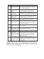
Liebert NXL UPS GUIDE SPECIFICATIONS for a 500/600/800kVA (50 or 60Hz) Single Module & 1+N Expandable Uninterruptible Power System 1.0 GENERAL 1.1 SUMMARY This specification describes the requirements for a DSP control Digital Uninterruptible Power System (UPS) using Vector Control Technology to increase the performance of power components and enable active conditioning of the load. The scope of this specification shall consist of the configuration of one or more UPS units designed to operate individually or with paralleled outputs. 1 + N expandable configuration shall consist of one or more single module UPS units (maximum of 6 units) that may be connected in parallel without the need for either an additional system control unit or a centralized main bypass static switch. The UPS shall automatically maintain clean AC power to the critical load within specified tolerances, without interruption during failure or deterioration of the mains power supply (for a specified duration as per battery run time). The UPS shall be expandable by paralleling additional modules of the same rating, to provide for module redundancy or load growth requirements. The manufacturer shall design and furnish all materials and equipment to be fully compatible with electrical, environmental, and space conditions at the installation sites that complies with applicable ROHS standard, applicable local codes, and standards. It shall include termination facilities to properly interface with the input AC power source and intended load. The UPS shall be designed for unattended operation except where operator start-up acknowledgment is required for safety reasons. 1.2 STANDARDS The UPS and all associated equipment and components shall be manufactured in accordance with the following applicable standards: • IEC 62040-1-1 • EN 50091-2 • IEC 62040-2 General and Safety requirements. : EMC Requirements : Uninterruptible Power System (UPS) part 2: EMC requirements • IEC 62040-3 • EN 60950-1 • EN 60529 : : : Design and Test Methods Information Technology equipment Degrees of protection provided by enclosures (IP Code) The UPS shall be CE marked in accordance with EEC directives 73/23 “low voltage” and 89/336 “electromagnetic compatibility.” The Quality System for the engineering and manufacturing facility shall be certificated to conform to Quality System Standard ISO 9001 for the design and manufacture of power protection systems for computers and other sensitive electronics and shall also be in conformance to ISO 14001 for environmental management system. 1.3 SYSTEM DESCRIPTION 1.3.1 Design Requirements A. For non-redundant operation (applicable/not applicable), the UPS system shall be sized to provide a maximum of 500/600/800kVA (delete whichever is not applicable) and a maximum of 450/540/720 kW (Delete whichever is not applicable) output at 0.9 output power factor. B. For redundant operation (applicable/not applicable), the UPS systems shall be sized to provide a maximum of ----------kVA and a maximum of --------kW output with one(1)module out of service (Insert applicable value). C. Load voltage and bypass line voltage will be 380/400/415 Vac, three phase and neutral. Input voltage will be 380/400/415 Vac, three phase. The UPS should be able to operate both on 3-phase 3-wire input system as well as 3-phase 4 wire input system. It should be in a position to accept two different electrical sources, one at it’s rectifier and another as it’s bypass supply. D. The battery system shall have a capacity to support ____kW UPS load for at least ___minutes at 25ºC ambient temperature. The battery will be installed: On open racks ( ) In battery cabinets ( ) E. The UPS system shall be expandable (up to a maximum of 8 units) in the future without any additional parallel card or centralized static switch. 1.3.2 Modes of Operation The UPS system shall operate as a true on-line system in the following modes: A. Normal: The critical AC load is continuously powered by the UPS inverter(s). The rectifier/charger(s) derives power from the mains AC power supply source converting this to DC power to supply the inverter(s), while simultaneously float charging the battery system. Power supplied by the UPS inverter(s) shall remain within close tolerances, at rated voltage and frequency. B. Emergency: Upon failure of the mains AC power supply source, the critical AC load is powered by the inverter(s) which, without any switching, obtain power from the battery system(s). There shall be no interruption in power to the critical load upon failure or restoration of the mains AC power supply source. C. Recharge: Upon restoration of the mains AC power supply source, power to the rectifier/charger(s) initially is restricted by a gradual power walk-in. Following this relatively short power walk-in period, the rectifier/charger(s) power the inverter(s) and simultaneously recharge the battery. This shall be an automatic function and shall cause no interruption to the critical load. D. Static Bypass: If the inverter fails, or the inverter overload capacity is exceeded, or upon receipt of a manual transfer command from the user interface, and at this time the inverter is synchronous with the bypass, the inverter static switch shall perform a transfer of the load from the inverter to the bypass source with no interruption in power to the critical AC load. If the inverter is asynchronous with the bypass, the inverter static switch will perform a transfer of the load from the inverter to the bypass static switch with interruption in power to critical AC load. This interruption must be less than 20ms (50 Hz), or less than 16.67ms (60 Hz), selectable. E. Off-Battery or Frequency Converter: If the battery system only is taken out of service for maintenance or the UPS is used as a frequency converter, it is disconnected from the rectifier/charger and inverter by means of an external disconnect breaker. The UPS shall continue to function and meet all of the specified steady-state performance criteria, except for the power outage back-up time capability. F. Source Share Mode: A part of the critical AC load is supplied by mains AC input, and the remainder of the critical AC load is supplied by the battery. This mode shall be user-activated and the ratio of the mains AC input power is programmable from 20% to 100% of the rated UPS power. This mode will be used in generator mode when a smaller capacity generator power is employed to support a larger rating UPS system. This function will be activated through a dry contact signal that will intimate UPS that that is running on Generator. G. ECO Mode (for single UPS only): In economic operation mode, the bypass is the preferred source of the load while the inverter is in stand-by mode. This is a user selectable mode and possible only while the mains AC supply voltage is within an acceptable voltage window (±10%) and frequency (±2 Hz). Failure of the bypass AC supply and frequency to remain within these pre-defined limits results in transfer of the load to the inverter. In this mode, the efficiency shall be 97%. H. Parallel (1+N Expandable): For higher capacity or higher reliability, the UPS outputs (3ph/4W) can be directly paralleled; parallel controllers in every UPS automatically share the load. Each UPS module shall be capable of operation in parallel and the maximum parallel capacity is up to six times the nominal load of each unit composing the system. I. Master / Slave Passive Redundancy (also known as Hot Standby): The master unit connects to the critical AC load and the slave unit connects to the bypass of the master unit. J. Auto-Restart Mode: If the battery system was completely depleted due to prolonged AC mains failure and the inverter shuts down when the battery reaches the End of Discharge Voltage (EOD), the UPS system can be programmed to auto-recovery after EOD after a set variable time. This mode and delay time is configurable via the service software or LCD panel. K. Maintenance Bypass: A second bypass circuit contained in the UPS cabinet identified as the maintenance bypass line is included to enable a raw mains supply to be made available to the load for carrying out a scheduled maintenance or troubleshooting. The bypass circuit is manually selected by switching the maintenance bypass power switch in the OFF position. L. Intelligent Parallel Mode of Operation: This mode will be user enabled or disabled mode and will be applicable for a N+1 UPS system. In case the load is smaller than installed UPS capacity, UPS should be able to intelligently detect load level and switch-off one or more active UPS modules, keeping sufficient numbers of modules active to support load without getting overloaded and still maintaining required level of redundancy, settable by the user. The switched off module should automatically become active and connected on-line in case the load increases and demands more active modules to support it or maintain redundancy. A rotational designation method will be applied to decide which UPS module will get switched off/on. It should also be possible to schedule switching off/on particular number of active modules during off-peak and peak hours of operation. M: Regeneration Mode of Operation: The UPS should be equipped with a feature where it will not need any additional, external load bank to run a full-load test of it’s rectifier, inverter and static switch components. In this mode, during on-site load testing, the UPS should be able to feed back the power to it’s utility and thus will consume only it’s losses from utility sources. With help of this Regeneration mode of operation the UPS should be able to perform a battery run-time test at site, without deploying actual load bank, 1.3.3 Performance Requirements The UPS is VFI classified (according to IEC 62040-3) producing an output waveform that is independent of both the input supply frequency and voltage. 1.3.3.1 UPS Module AC Input A. Input voltage range for rectifier operation: -25% to +15% of 380/400/415 Vac With mains at -15% and suggested battery elements, the UPS should maintain the rated output voltage at rated load but need not guarantee float charge to battery; the battery should not discharge below -15% till 290V input voltage. B. Frequency Range: 47 – 63Hz C. Power walk-in: 5-30seconds (selectable) D. Input Power Factor: should be 0.86/0.90/ 0.95 (Select whichever is applicable) at full load. E. Input Current Limit: Maximum of 115% normal full load input current. (selectable from 50% to 100% for generator operation.) F. Temperature Compensated Charging: Above 25ºC the battery charge voltage shall be settable to reduce from 0 to 5mV per cell per ºC in order to optimize on the battery lifetime. G. Current Harmonic Distortion: < 3% 1.3.3.2 UPS Module AC Output A. Load Rating: 100% continuous load rating at 35ºC/40 ºC (Select whichever is applicable) for combination of linear and non-linear loads as per IEC 62040-3 standard) B. Voltage Regulation: 1% steady state for balanced load, 2% for 100% unbalanced load as per IEC 62040-3, 5.3.1. C. Nominal Output Power Factor: 0.9 for KW rating of UPS. However UPS module should be able to operate for load power factor from 0.5 lag to 0.8 lead with suitable de-rating factor. D. Frequency Regulation: ± 1Hz synchronized with bypass source, ± 0.05Hz free running or on battery operation. E. Frequency Slew Rate: 0.1 up to1.0Hz per second (selectable) F. Efficiency: Defined as output kW / input kW at a load power factor of 0.9 lagging. 800kVA: 92.5% efficient at full rated load for 12 pulse rectifier. G. Phase Imbalance: 120º ±0.5º el. for balanced loads. 120º ±1º el. for 100% unbalanced loads H. Voltage Transients: ± 5% for 100% output load step (in accordance with IEC 62040-3). I. Transient Recovery Time: To within 95% of steady state output voltage within 20ms. J. Voltage Distortion (at 100% rated load with crest factor 3:1): <2.5% Ph/Ph voltage total harmonic distortion (THDv) K. Overload Capability at Rated Output Voltage: UPS should be able to support following overload conditions. 110% of rated load for 60 minutes. 125% of rated load for 10 minutes. 150% of full load for a minimum of 1 minute. L. Current Limit: 150% of rated three phase current for up to 5 seconds (in accordance with EN 50091-1-1.) 290% of rated single phase current for up to 5 seconds (in accordance with EN 50091-1-1.) 1.3.3.3 UPS System Bypass A. Voltage Range: +10% Upper Limit, -15% default Lower limit, (other values should be selectable with software setting) B. Frequency Range: ± 5% (other values should be selectable with software setting) C. Overload Capability: (specified without fuses) 11.5 times for 10ms 10.5 times for 20ms 7.7 times for 100ms 4.6 times for 5 seconds 1.1 times continuous 1.3.3.4 Earthing The AC output neutral shall be electrically isolated from the UPS chassis. The UPS chassis shall have an equipment earth terminal. Provisions for local bonding are to be provided. 1.4 ENVIRONMENTAL CONDITIONS 1.4.1 Operating Ambient Temperature UPS: 0ºC to 35ºC/40ºC (Select whichever is applicable) Battery: 25ºC for optimum battery performance. 1.4.2 Storage/Transport Ambient Temperature UPS: -25ºC to 70ºC. Battery: 20ºC for optimum battery storage. 1.4.3 Relative Humidity : 0 to 95%, non-condensing. 1.4.4 Altitude Operating: ≤1500m above sea level without de-rating (de-rate power by 1% per 100m between 1500m and 3000m). Storage: ≥1500m above sea level for continuous storage. 1.4.5 Electrostatic Discharge The UPS shall be able to withstand an electrostatic discharge compliant to IEC 801-2 level 3 (8kVA through air, 6kV contact) without damage to equipment or the connected load. 1.5 UPS DELIVERY SUBMITTALS The specified UPS shall be supplied with one (1) user manual to include details of: A. Functional description of the equipment with block diagrams. B. Detailed installation drawings, including all terminal locations for power and control connections for both the UPS and battery system. C. Safety precautions. D. Step-by-step operating procedures E. General maintenance guidelines The UPS shall be supplied with a record of pre-shipment final factory test report. 1.6 WARRANTY 1.6.1 UPS Warranty The UPS manufacturer shall warrant the unit against defects in workmanship and materials for 12 months after initial start-up or 15 months after ship date, whichever comes first. 1.6.2 Battery Warranty The battery manufacturer's standard warranty shall be passed through to the end user. 1.7 QUALITY ASSURANCE 1.7.1 Manufacturer Qualifications A minimum of twenty years experience in the design, manufacture and testing of solid-state UPS systems is required. The manufacturer shall be certified to ISO 9001 and ISO 14001. 1.7.2 Factory Testing Before shipment, the system shall be fully and completely tested to ensure compliance with the specification. 2.0 PRODUCT 2.1 FABRICATION 2.1.1 Materials All materials of the UPS shall be new, of current manufacture, high grade and shall not have been in prior service except as required during factory testing. All active electronic devices shall be solid-state. Control logic and fuses shall be physically isolated from power train components to ensure operator safety and protection from heat. All electronic components shall be accessible from the front without removing sub-assemblies for service access. 2.1.2 Wiring Wiring practices, materials and coding shall be in accordance with the requirements of IEC. All electrical power connections shall be torque to the required value and marked with a visual indicator. Provision shall be made in the cabinets to permit installation of input, output, and external control cabling. Provision shall be made for top, side, or bottom access, allowing for adequate cable bend radius to the input and output connections. 2.1.3 Construction The UPS shall be housed in an IP20 enclosure, designed for floor mounting. The UPS shall be structurally adequate and have provisions for hoisting, jacking, and forklift handling. 2.1.4 Cooling Adequate ventilation shall be provided to ensure that all components are operated well within temperature ratings. Temperature sensors shall be provided to monitor UPS internal temperature. Upon detection of temperatures in excess of manufacturer’s recommendations, the sensors shall cause audible and visual alarms to be sounded at the UPS control panel. A separate room ambient temperature sensor shall be provided to allow control of the battery charging voltage with change of temperature. On request shall be available the Fan Failure Alarm Indicator that provide the alarm on UPS front panel or remotely when one or more fans are faulty. No clearance shall be required at the side and rear of the UPS for the purpose of ventilation or otherwise. 2.2 EQUIPMENT 2.2.1 UPS System The UPS system shall consist of a single module unit for stand-alone configuration or an appropriate number of single module units to meet capacity and redundancy requirements. Each UPS module shall consist of a 12Pulse rectifier/charger (with 30º phase shifted transformer for 12-pulse rectifier), three-phase inverter with associated transformers, mains bypass static switch, inverter static transfer switch, protective devices, passive filter, and accessories as specified. 2.2.2 Configurations The UPS system shall consist of either a single module unit, or more (up to a maximum of six) of the same kVA rating. Systems greater than one module shall operate simultaneously in a parallel configuration with the load shared equally among the connected modules. With the exception of a single module configuration, the system shall be redundant or non-redundant as stated elsewhere in this specification. A. Non-redundant system: All the modules making up the UPS system shall supply the full rated load. If a module should malfunction, the load is to be transferred, automatically and uninterrupted, to the bypass line by the use of the static mains bypass switch. B. Redundant system: The UPS system shall have one or more module(s) than required to supply the full rated load. The malfunction of one of the modules shall cause that module to be disconnected from the critical load and the remaining module(s) shall continue to carry the load. Upon repair of the module, it shall be reconnected to the critical load to resume redundant operation. Any module shall also be capable of being taken off the critical load manually for maintenance without disturbing the critical load bus. Module redundancy level shall be a predefined number of modules that are required to supply the full rated load. With the number of connected modules equal to this value, a malfunction of another module shall cause the load to be transferred automatically and uninterrupted to the bypass line by the use of the static mains bypass switch. 2.2.3 System Protection A. The UPS shall have built-in protection against: surges, sags, and over-current from the AC source, overvoltage and voltage surges from output terminals of paralleled sources, and load switching and circuit breaker operation in the distribution system. The UPS shall be protected against sudden changes in output load and short circuits at the output terminals. B. The UPS shall have a built-in protection against permanent damage to itself and the connected load for all predictable types of malfunctions. Fast acting software and control with a true DSP design shall be used to detect failure and abnormal conditions. Upon detection of the failure or abnormal condition, the DSP software shall gate-off the circuit to protect against cascading failure of solid-state devices Additional current limiting devices such as fast-acting fuses and contactors shall back-up the software to provide maximum protection. Internal UPS malfunctions shall cause the module to trip off-line with minimum damage to the module and provide backup information to maintenance personnel regarding the reason for tripping off line. The load shall be automatically transferred to the bypass line uninterrupted, should the connected critical load exceed the capacity of the available on-line modules. The status of protective devices shall be indicated on the LCD graphic display screen on the front of the unit. C. The UPS system shall be capable of protecting itself from excessive retransfers in an hour due to inverter overload. The number of retransfer time limit shall be settable from 1-10 times in an hour. If the limit was reached, the load shall be transferred to bypass source permanently until such time that the load returns to normal condition. This feature is an important factor to increase the MTBF of the UPS system and shall act as guide or notification for the end users to reduce the load or addition of UPS system due to load growth. 2.2.4 Diagnosis The UPS system shall be capable of self-diagnostics to monitor parameters of main modules such as rectifier, inverter, and monitor. It shall also have in its memory important data such as fault records, alarms, and history logs. 2.3 COMPONENTS 2.3.1 Rectifier/Charger The term rectifier/charger shall denote the 12Pulse solid-state rectifier equipment and controls necessary to convert AC to regulated DC for input to the inverter and for charging the battery. A. Input Current Total Harmonic Distortion: Overall current harmonic distortion at the input of rectifier should < 3%. B. AC Input Current Limiting: The rectifier/charger shall include a circuit to limit AC input current to 115% of the full input current rating. The UPS should have a standard option that will provide input current limiting to 100% during generator operation, on receipt of an external low voltage signal. C. Battery Charge Current Limiting: The rectifier/charger shall include a circuit to limit the battery charging capacity to 15% UPS output KW rating. An optional secondary circuit shall reduce the charging current to 0% on receipt of an external low voltage signal, during generator operation. D. Battery Charge Compensation: The rectifier/charger shall automatically adjust the battery float charging voltage by ±5mV per cell per ºC when used in conjunction with an optional remote temperature sensor. The nominal DC bus voltage, and therefore battery float voltage & battery end cell voltage should be (Select whichever is applicable). E. Input Power Walk-in: The rectifier/charger shall provide a feature that limits the total initial power requirements to 20% of rated load, and gradually increases power to 100% of full rating over a 10 second time interval. For redundant configuration, the power walk-in starting time shall be delay configurable from 5 to 30 seconds in order to reduce the impact to the Generator. F. Input Isolator: The rectifier/charger shall have an input isolator and shall be fuse protected. The isolator shall be of the frame size to supply full rated load and recharge the battery at the same time G. Fuse Protection: Each AC phase shall be individually fused with fast acting fuses so that loss of any semiconductor shall not cause cascading failures. H. DC Filter: The rectifier/charger shall have an output filter to minimize ripple current in to the battery. The AC ripple voltage of the rectifier DC output shall not exceed 1% RMS of the float voltage. The filter shall be adequate to ensure that the DC output of the rectifier/charger will meet the input requirements of the inverter without the battery connected. I. Battery Recharge: In addition to supplying power to the load, the rectifier/charger shall be capable of producing battery charging current sufficient to replace 95% of the battery discharge power within ten (10) times the discharge time. After the battery is recharged, the rectifier/charger shall maintain the battery at full charge until the next emergency operation. In case the load is less that UPS capacity, the balance, reserve rectifier capacity should be usable to increase battery charging current. 2.3.2 Inverter The term inverter shall denote utilizing the latest IGBT switching Vector Controlled DC – AC converter (also known as Space Vector Pulse Width Modulation) that provides the second conversion phase, which is, convert DC from the rectifier/charger or battery to provide AC power to the critical load. The inverter shall be solid-state, capable of providing rated output power. The inverter shall be of Vector Controlled design using the latest DSP and utilize insulated gate bipolar transistors (IGBTs), switching at high frequency in order to minimize output voltage distortion and cross currents in redundant configuration. A. Overload Capability: The inverter shall be able to sustain an overload across its output terminals up to 150% with ±5% output voltage regulation. The inverter shall be capable of supplying at least 150% current under short circuit conditions for 5 seconds if the Bypass source is not healthy. If the bypass supply is healthy, inverter should transfer the load to bypass during a short circuit current overload beyond 150% and disconnect itself from critical bus. B. Output Frequency: The inverter shall track the bypass mains supply continuously providing the bypass source maintains the rated frequency (of either 50 or 60Hz). The inverter will change its frequency at 0.1Hz per second (adjustable from 0.1 to 1.0Hz per second) to maintain synchronous operation with the bypass. This shall allow make-before-break manual or automatic transfers of the load between the inverter and the bypass mains supply. If the bypass mains supply frequency falls outside of these limits, the inverter shall revert to an internal digital oscillator and hold the inverter output frequency to within ±0.01Hz of the rated frequency for steady state and transient conditions. Drift shall not exceed 0.1% during any 24 hour period. Total frequency deviation, including short time fluctuations and drift, shall not exceed 0.1Hz from the rated frequency. C. Phase-to-Phase Balance: System logic (DSP) shall provide individual phase voltage compensation to obtain phase balance of ±1% under all conditions including up to 100% load unbalance. D. Fault Sensing and Isolation: Fault sensing shall be provided to isolate a malfunctioning inverter from the critical load bus to prevent disturbance of the critical load voltage beyond the specified limits. The inverter output static switch shall be switched off to isolate a malfunctioning module from the critical load. E. Battery Protection: The inverter shall be provided with monitoring and control circuits to protect the battery system from damage due to excessive discharge. Shutdown of the inverter shall be initiated when the battery has reached the end of discharge (EOD) voltage. The battery EOD voltage shall be calculated and automatically adjusted for reduced load conditions to allow for extended autonomy periods without damage to the battery. Automatic shutdown control shall not be a function of discharge time. F. Self-Ageing: The inverter shall be able to provide up to 80% load to the UPS system itself to test its complete functionality. This shall be done via the service software parameters setting. The UPS system shall display all values such as input & output voltages, input & output kW, frequency, currents, etc. This self-ageing mode shall be done to replace the traditional “resistive load testing” of the UPS system at the installation site. 2.3.3 Static Bypass When a scheduled maintenance is required or when an overload condition is sustained for a time period in excess of the inverter output capability or due to malfunction, a bypass circuit shall be provided for each single module that forms as an integral part of the UPS system. The modular bypass circuit(s) shall provide for isolation of the inverter(s) and provide a path for power directly from an alternate AC bypass source. The UPS logic control shall constantly monitor the availability of the static bypass line in case of a need to perform a transfer. The bypass of each module shall consist of a bypass static switch, operating in conjunction with the inverter output static switch. The static switches shall be solid state devices that, operating simultaneously, can instantaneously connect the load to the alternate AC source. A. Manual Load Transfers: A manual load transfer between the inverter output and the alternate AC source shall be initiated from the control panel. The transfer shall be no-break utilizing the inverter output and bypass static switch.. B. Automatic Load Transfers: An automatic load transfer between the inverter output and the alternate AC source shall be initiated if an overload or short circuit condition is sustained for a period in excess of the inverter output capability or due to a malfunction that would affect the output voltage. Transfers caused by overloads shall initiate an automatic retransfer of the load back to the inverter only after the load has returned to a level within the rating of the inverter source. C. Back-feed Protection: The static bypass shall be provided with detection and control circuits, to be used in conjunction with external automatic switchgear, in order to disconnect the bypass line in the event of a short-circuit being detected in the solid-state devices that form the bypass static transfer switch. The purpose of this requirement is to prevent the risk of electrical shock on the distribution system when the normal source of power is disconnected. Furthermore, failure of bypass SCR’(s) shall not back-feed UPS power to the bypass distribution while the UPS is operating on battery mode. 2.3.4 Internal Maintenance Bypass A fully rated bypass circuit shall be fitted on all single module UPS systems to provide an alternative path for power flow from the alternate AC supply to the critical load for the purpose of maintaining the UPS when it is completely powered down. A maintenance bypass interlock shall activate the static bypass circuit to protect against cross-feed between inverter and bypass circuits if the Maintenance Bypass Switch is closed before the inverter is shutdown. 2.3.5 Human Machine Interface A. UPS Display and Control Panel: Each UPS module shall be equipped with a large LCD touch screen color display. This shall automatically provide all information relating to the current status of the UPS or the system load, respectively, as well as being capable of displaying metered values. The display shall be menu-driven, permitting the user to easily navigate through operator screens. The LCD screen shall also display a Prompt Window to alert users of UPS certain conditions that require confirmations of a command (see table below). The user should be able to view UPS operation manual & configure user selectable options directly from the display without any external tool. No. 1 2 3 4 5 6 7 8 9 Prompt Transfer with interrupt, confirm or cancel The load is too high to be transferred with interrupt This operation leads to output shutdown, confirm or cancel This operation leads to inverter overload, confirm or cancel Turn on more UPS to carry current load Battery will be depleted, confirm or cancel System selftest finished, everything is ok System selftest finished, please check the current warnings Enter control password 10 Battery selftest condition is low, please check battery state and loadlevel 11 Freshening charge condition is low, please check battery settings and state Meaning Inverter and Bypass supplies are not synchronised and any load transfer between the supplies will cause a brief load interruption The total load must be less than the capacity of one unit to allow a parallel system to perform an interrupted transfer from bypass to inverter No alternative supply is available and any Inverter Off operation will cause the load to be de-energised Turning off this inverter will lead to the overload of remaining inverter(s) in a parallel system The number of paralleled inverters already turned on is insufficient to carry the existing load Battery capacity test discharges the battery 100%. This prompt apears to require your confirmation. Cancelling the test will ends the test and transfers the UPS to Normal mode No action required Check the current record window Required for battery or UPS test Battery test condition is not met. Please check whether the battery is in boost charge state and the load level meet the battery test conditions. To initiate the battery test, the load must range between 20% and 80% This prompt appears when you select the freshening charge command while the freshening charge condition is not met (such as no battery, charger failure) B. Metered Values: A DSP shall control the display functions of the monitoring system. All three-phase parameters shall be displayed simultaneously. All voltage and current parameters shall be monitored using true RMS measurements for accurate (±1%) representation of non-sinusoidal waveforms typical of computers and other sensitive loads. The following parameters shall be displayed: Main Input: Three phase Line to Line voltage Main Input Frequency Bypass: Bypass input Line to Neutral voltage Bypass input Line to Line voltage Bypass input Frequency UPS Output: Per phase output voltage Per phase output current Line to Line voltage Output frequency Output power factor Local Load: Load on each phase (% of total load) Active power, apparent power, and reactive power of each phase Load crest factor System Load: Active power, apparent power, and reactive power Single system, no parallel data Battery: Battery bus voltage Battery bus current Internal battery temperature ºC Battery run time (remaining) Battery boost charging Battery float charging Battery not connected Records / Event History: Displays 512 events log indicating system status and time stamp for each event Settings: Language Contrast Date format Date & time Com1 baud rate, Com2 baud rate, Com3 baud rate RS-232 & RS-485 Password Command: Battery maintenance test Battery capacity test System test stop test Freshening charge C. Power Flow Mimic: Each UPS module shall be equipped with a mimic to indicate power flow to the critical load along with an indication of the availability of the rectifier/charger, battery, static bypass, inverter, and load. The mimic shall provide a quick and easy indication of load level (displayed on LCD), to include overload conditions (displayed on LCD). This power flow shall also be seen in the LCD display. D. Alarms and Status Information: Alarm and status conditions shall be reported at a single module UPS system or at the paralleled module or both. The display and control panel shall report the alarms and status information listed below. Each alarm shall be visually displayed in text form and an audible alarm will sound for each alarm displayed (see table below). Alarm message Rectifier comm. fail Rectifier block Rectifier current limt Rectifier over temp. REC drive circuit fault REC input Ph. missing Mains Volt abnormal Mains undervoltage Mains freq. abnormal Mains phase reversed Control power 1 fail Control power 2 fail Soft start fail Input filter fault Filter contactor fault Filter overcurrent DC bus over voltage Unit over load Alarm message Bus capacitor overvolt EPO Input disconnect open Input disconnect closed Normal mode Source share mode PPF online PPF disconnecting Auto start Battery mode No battery Battery Room Alarm BCB open BCB closed Battery float charging Battery boost charging Battery discharging Battery period testing System over load Batt. capacity testing Unit over load timeout Battery ground fault Byp. abnormal shutdown Bypass unable to trace Battery maint. testing Battery end of discharge Bypass phase reverse Battery overtemp. Load impact transfer Transfer time-out Load sharing fault DC bus abnormal System transfer Parallel board fault Parallel connect fault Bypass over current LBS Active LBS abnormal Byp. induct overtemp. Input fuse fail Ambient overtemp. Battery fuse fail Battery fault Battery maintained Battery low pre-warning Setting save error Inverter comm. fail Parallel comm. fail Inverter over current INV drive circuit fault Inverter asynchronous Inverter output abnormal Inverter overtemp. Inverter STS fail Alarm message Protocol version clash UPS system testing Inverter in setting Rectifier in setting Generator connected REC flash update INV flash update Monitor flash update Unit off confirm System off confirm Fault reset Alarm silence Turn on fail Alarm reset Transfer confirm Transfer cancel Manual turn on Manual turn off Bypass disconnect closed Bypass disconnect open Maint. disconnect closed Maint. disconnect open Output disconnect closed Output disconnect open Check UPS output Output disabled Normal mode Battery mode Source share mode Bypass mode Static Sw. overtemp. Byp. feedback fault Bypass abnormal Fan fault Bypass STS fail Operation invalid E. Inverter ON/OFF: Each UPS module shall be equipped with an inverter ON/OFF button which will transfer the load from all UPS modules to the bypass mains supply, if it is available. The inverter ON/OFF button shall be activated by pressing and holding the buttons for approximately 2 seconds until a beeping sound is heard. F. EPO Button: Each UPS module shall be equipped with an EPO button and shall be housed beneath a safety cover to protect against inadvertent operation. It shall be conspicuously located at the UPS doors. The EPO button shall be activated by pressing and holding the button for approximately 2 seconds, after which, it disables the entire static switch block, inverter, rectifier / charger, and trips the battery circuit breaker. It shall also be used to trip the external input circuit breaker to disconnect from UPS input power or AC mains supply (circuit breaker connected to an external trip facility). 2.3.6 Power Supply Each UPS module shall be equipped with redundant control power supply boards. Redundant power supplies will feed a DC dual-bus for control power supply that will be used through out the unit to prevent any single-point power supply failure modes. 2.3.7 Load Bus Synchronizer (LBS) Each UPS module shall be equipped with a Load Bus Synchronizer (LBS) functionality to assure that the output of two independent UPS systems (or parallel systems) remain synchronized even when the UPS systems are operating in different modes ( bypass, inverter, or battery). The LBS shall be used in conjunction with a Static Transfer System to achieve Dual Bus Configuration to support single input loads. The LBS shall be able to synchronize UPS units of the same type and brand. The UPS system shall also support an optional LBS adapter to synchronize UPS units of different type and brand (with two completely different sources of incoming power). No additional external box should be applied for LBS between the same model of UPS system from same manufacturer. 2.3.8 Firmware The UPS system shall have the ability to be updated with the latest release of firmware version or the same release version as needed. The flash update shall be done to the Monitor Board, Rectifier Board, and Inverter Board so as to be loaded with the latest release version as recommended by the manufacturer for control enhancement. Flashing of firmware to the replacement board needed to be loaded with the old release version for compatibility with other firmware shall also be possible. This shall be done via the service software parameter setting used by the commissioning engineers and shall also be possible using remote connectivity. 2.4 OPTIONAL COMMUNICATIONS A. SNMP/HTTP Network Interface Card: The UPS shall have an optional, internally fitted, Simple Network Management Protocol (SNMP) to provide real time status information over a 10/100 base T Ethernet connection. The SNMP will support SNMPv1, and shall be MIBII compliant for integration into Network Management System. This card support traps for up to 8 destinations and supports LGP and MIBII definitions. UPS information will also be available over the network by using a web browser via a HTTP page. The SNMP supports static as well as DHCP, and boot modes for plug-and-play network installation. It shall also be configurable via HTTP, Telnet, FTP, web page, or serial interface. The card provides configuration and control security through a user name and password. The cards firmware can also be updated such that future releases can be downloaded to enjoy card enhancements. B. RS-485 Interface Card: The UPS shall have an optional, internally fitted RS-485 interface card that will provide real time status information over a 2 or 4-wire RS-485 connection. This interface will support MODBUS, JBUS, and RTU protocol. C. Relay Card: The UPS shall have an optional, internally fitted relay card that will provide real time status information of the following UPS conditions: UPS ON / UPS FAILURE UPS ON BATTERY UPS ON BYPASS BATTERY LOW The relay card will function via a contact closure interface rated at 24Vdc, 1A. The card will allow interfacing with AS400 or remote monitoring devices, such as a Remote Alarm Panel. 2.4.1 Software Compatibility: The UPS shall have optional software for monitoring, control, and event management for almost all available operating systems. The available solutions shall provide: Users with basic UPS operating status plus automated shutdown of computers operating systems in the event of an extended power outage. Cost-efficient centralized monitoring and event management of UPS, environmental and Power systems that can utilize an existing infrastructure network. 2.5 OTHER OPTIONS: 2.5.1 Battery Circuit Breaker (BCB) Each UPS module shall have a properly rated circuit breaker to isolate it from the battery. This Battery Circuit Breaker is to be housed in a separate enclosure for wall mounting, or mounted inside an optional battery cabinet and must be installed as close as possible to the battery systems and UPS. It shall contain a BCB and a BCB control board. It shall function as required by the E.P.O. button and the BCB shall trip once the E.P.O. button is pressed. The UPS should be able to control/trip up to 4 battery circuit breakers for up to 4 strings of battery that can be connected. 2.4.2 Battery Cabinet: Batteries shall be housed in a suitable cabinet matching in height, and depth of the UPS modules 2.4.3 External Battery Temperature Sensor: To ensure temperature compensated charging to protect battery life, a battery temperature monitoring probe is necessary to monitor the battery enclosure temperature rise caused by the AC mains failure and of the battery’s internal resistance when operating. The probe system includes one battery temperature sensor and one temperature transport. 2.4.3 Static Transfer Systems: To provide automatic dual source switching for redundant UPS units connected to two different sources of incoming AC power. It shall also provide isolation, distribution, computer grade grounding, and power monitoring to the critical loads. 2.4.4 Load Bus Synchronizer Kit: To provide communication link between two or More redundant UPS systems independent output bus (either two independent single units or two independent parallel systems each composed of up to eight modules) to maintain synchronization. The LBS functionality should be able to synchronize multiple bus systems, up to 6 buses. 2.4.5 Harmonic Filter: To minimize harmonics reflected back to the upstream distribution to less than 3% THDi and improve input Power Factor to 0.95. This should be achieved by 12pPulse rectifier combined with active and passive filter combination. 2.4.5 Battery Monitoring System : An optional battery monitoring system should be offered to monitor multiple strings of battery where individual 12v blocks of battery can be monitored. Battery monitoring system should use resistance method to detect health of batteries.