1
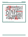
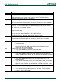
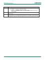
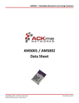
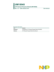
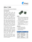
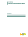
UM10854 LPC54102 SPM Solution Hardware User Manual (OM13078) Rev. 1.1 — 26th October 2015 Hardware User manual Document information Info Content Keywords LPC54102, LPC54100, Sensor Processing Abstract LPC54102 Sensor Processing/Motion Solution Hardware User Manual UM10854 NXP Semiconductors LPC54102 SPM-S Kit Revision history Rev Date Description 1.0 <20141104> First draft 1.1 <20151026> Added note on BMI160 and AMS001 component changes. Clarified use of correct LPCOpen package for different board builds. Contact information For more information, please visit: http://www.nxp.com For sales office addresses, please send an email to: [email protected] UM10854_OM13078 Hardware User manual All information provided in this document is subject to legal disclaimers. Rev. 1.1 — 26th October 2015 © NXP B.V. 2014. All rights reserved. 2 of 14 UM10854 NXP Semiconductors LPC54102 SPM-S Kit 1. Introduction The LPC54102 Sensor Processing/Motion Solution (SPM-S) combines the LPC54102 MCU and a range of MEMS sensors in a two board set, complemented by a software framework optimized for always-on sensing applications. The hardware consists of an LPCXpresso54102 board and Sensor Shield Board (SSB), developed by NXP for flexibility and ease of use. The solution can be used with a wide range of development tools, including the NXP’s LPCXpresso IDE, Keil uVision and IAR EWARM. Fig 1. LPC54102 Sensor Processing/Motion Solution The LPCXpresso54102 SPM-S includes the following features: UM10854_OM13078 Hardware User manual LPCXpresso54102 development board with: o Built-in Link2 high-speed USB based debug probe o Connectivity for external debug probes o Tri-color LED o Target Reset, ISP and WAKE buttons o On-board 1.8/3.3V or external power supply options All information provided in this document is subject to legal disclaimers. Rev. 1.1 — 26th October 2015 © NXP B.V. 2014. All rights reserved. 3 of 14 UM10854 NXP Semiconductors LPC54102 SPM-S Kit o Built-in MCU power consumption and supply voltage measurement for LPC54102 device and sensor board o UART, I2C and SPI port bridging from LPC54102 target to USB via Link2 device o FTDI UART connector o LPC54102 in LQFP64 package Sensor Shield Board with: o Bosch Sensortec sensors: BMI160 inertial measurement unit (BMI055 on earlier boards), BMC150 digital compass, BMM150 magnetometer, BMP280 pressure/temperature sensor o Murata pressure/temperature sensor o MAX44000 ambient light and proximity sensor o ACKme AMS001 (or AMS002 on earlier production units) Bluetooth LE module o IR remote control driver/receiver o Dual Knowles digital microphones o Headers for easy prototyping of additional SPI and I2C sensors Software o Free NXP Sensor Framework o Free Bosch Sensortec BSXlite sensor fusion library This manual covers features, configuration and use of the hardware in the Solution. For information on use of the Sensor Framework please refer to the Programmer’s Manual. The SSB is mounted on the expansion connectors of the LPCXpresso54102 during manufacture. The boards are configured for the default operation of the Sensor Framework software and its operation with the Bosch BSX Lite library. 2. Getting Started The flash memory of the LPC54102 MCU on the SPM-S is pre-programmed with an example application to show operation of the BSX Lite sensor fusion library within the NXP Sensor Framework. The example application streams board orientation information over the LPC54102 I2C port, via the on-board Link2 debug probe device’s USB port, to a host computer (running Windows 7, 8 or 10). The example renders a 3D teapot from the OpenGL library to represent orientation and movement of the board, using accelerometer, gyroscope and magnetometer data processed by the BSX Lite library. Earlier production units of the Kit were programmed with the LPCOpen 2.14.1 version of the example program (these kits have the ACKme AMS002 BTLE module and BMI055 IMU sensor). It is recommended that you download and use the latest (LPCOpen 3) software for best results. To run the example application follow these steps: 1) If you have not installed LPCXpresso IDE version 7.8 or later, and have not installed LPCScrypt on your computer, download and run the LPCXPresso Link2 UM10854_OM13078 Hardware User manual All information provided in this document is subject to legal disclaimers. Rev. 1.1 — 26th October 2015 © NXP B.V. 2014. All rights reserved. 4 of 14 UM10854 NXP Semiconductors LPC54102 SPM-S Kit USB driver package driver installer from: http://www.lpcware.com/content/nxpfile/lpcxpresso-link2-usb-driver-package. 2) Ensure JP5 is open (no jumper installed) on the LPCXpresso54102 to make the Link2 processor boot from internal flash memory. The factory-programmed Link2 flash image includes I2C to USB bridging support required to support the demonstration. Connect the host computer to the LPC54102 SPM-S board set at connector J6 using the supplied micro USB cable. Allow about 30 seconds for the board devices to enumerate the first time you connect it 3) Download the example Windows PC application available from the LPCOpen section of the lpcware website at this address: http://www.lpcware.com/content/nxpfile/lpcopen-software-development-platformlpc5410x-packages 4) Run the teapot.exe application. A 3-dimensional rendition of a multi-colored teapot will be displayed. The board’s location and movement will be represented by the teapot’s orientation. By pressing the “s” key on your computer the orientation can be reset to match the board’s orientation. Note that the board’s orientation can be affected by magnetic and electrical fields. NXP and Bosch Sensortec continue to improve and enhance the Sensor Framework and BSX Lite library. Check http://www.lpcware.com/content/nxpfile/lpcopen-softwaredevelopment-platform-lpc5410x-packages for the latest updates to the firmware image for this application. If you have any issues running the example program please download the example code for your tool chain of choice mentioned in step (3) above. 3. LPCXpresso54102 Board The details of the LPCXpresso54102 board described in this manual are limited specific to those specific to this Solution; for a full description of the board’s features please refer to the LPCXpresso54102 User Manual (UM10855), available at http://www.lpcware.com/lpcxpressov3boards. 3.1 Power supply configuration The LPCXpresso54102 includes on-board regulators to supply 3.3V or 1.8V to the LPC54102, configured using JP7. The supply is configured to 3.3V by default. 3.2 Expansion connector The LPC54102 SPM-S utilizes the LPCXpresso54102 expansion connector to interface to the SSB. Since the Arduino Uno Revision 3 standard does not provide enough signals to support all the functionality required for the SSB, the LPCXpresso54102 board has an extended version of that connection standard. The new expansion connector footprint has been designed for future expansion and provides more connections than are needed to support the LPC54102, so not only a subset of the connectors is installed. 3.3 Supply current/power measurement The LPCXpresso54102 has built-in power measurement circuitry, controlled by its onboard Link2 debug probe. This circuitry can measure power consumed by the LPC54102 by sampling the voltage dropped across a sense resistor on the board using a differential amplifier, sampled at up to 200kHz by a 12-bit ADC. The power consumed by the SSB can be measured as well, since the SSB has a similar differential amplifier/sense resistor circuit. An analog multiplexer is used to select between these measurement sources. The UM10854_OM13078 Hardware User manual All information provided in this document is subject to legal disclaimers. Rev. 1.1 — 26th October 2015 © NXP B.V. 2014. All rights reserved. 5 of 14 UM10854 NXP Semiconductors LPC54102 SPM-S Kit Link2 is not user-programmable, so NXP has developed a power measurement tool to utilize these features. Please visit http://www.lpcware.com/lpcxpressoboards for more information. The LPC54102 SPM-S is design for flexibility and hence has circuitry that may not be required for all applications. Before making power measurements, carefully review the schematics of both boards to understand potential current leakage paths, since these may introduce power consumption that is not relevant to the end application. For example, review the jumpers/solder jumpers related to the sensors, I2C/SPI/UART connections to the Link2, tricolor LED and BTLE module to understand the options to reduce power supplied to these parts of the board set. 3.4 Host process connections For applications where the LPC54102 will be used as a slave device, such as in a sensor hub, the PMod™ connector on the LPCXpresso54102 provides a convenient way to connect an external processor. This connector provides connectivity to the LPC54102 SPI0 and I2C2 ports. 4. Sensor Shield Board The Sensor Shield Board (SSB) is custom-designed expansion board, based on extended version of the Arduino Uno Revision 3 standard. The board includes multiple sensors from Bosch Sensortec and other vendors. Note that the design includes pads for use with other sensors that are not yet generally available. 4.1 Sensors This section provides a brief overview of the sensors on the SSB. 4.1.1 Bosch Sensortec (motion and pressure/temperature sensors) The SSB incorporates four Bosch Sensortec sensors: BMI055 or BMI160 inertial measurement unit, BMC150 eCompass, BMM150 magnetometer and BMP280 pressure/temperature. All of these sensors are connected to the same I2C bus (I2C0 signal) and all have interrupt output lines to the LPCXpresso54102 board except the BMP280. Please refer to http://www.bosch-sensortec.com/ for more information on these sensors. The BMI055 (if fitted) has a minimum supply voltage of 2.4V, so cannot be used with a 1.8V supply SSB supply voltage setting; it can be used with the LPCXpresso54102 VDD set to 1.8V. 4.1.2 Proximity/ALS Sensor A Maxim MAX44000 ambient light and proximity sensor is provided on the SSB, along with an IR LED to be used in conjunction with that sensor to implement a proximity detection function. For further information on this device please refer the http://www.maxim-ic.com. 4.1.3 Murata pressure sensor A Murata ZPA2326 pressure & temperature sensor is installed on the SSB. This sensor cannot be used with 3.3V I/O, so is not connected to the I2C bus by default in order to prevent accidental damage to the sensor. To use this sensor ensure that the LPC54102 is set to 1.8V (JP7 installed in location 1-2 on the LPCXpresso54102) and use a UM10854_OM13078 Hardware User manual All information provided in this document is subject to legal disclaimers. Rev. 1.1 — 26th October 2015 © NXP B.V. 2014. All rights reserved. 6 of 14 UM10854 NXP Semiconductors LPC54102 SPM-S Kit soldering iron to short SJ14 and SJ17. For further information on this sensor please refer to http://www.murata.com. 4.2 Bluetooth Low Energy (BLE) Module An ACKme AMS001/AMS002 BTLE module is included on the SSB. This module provides a fully integrated BTLE sub-system which can be configured by and receive/transmit data from/to the LPC54102 via a UART connection. A debug port connector for the AMS002 is provided on the SSB, but this should not be used unless advised to do so by NXP or ACKme. For more information on this module please visit http://ack.me. Note that ACKme is a brand of Zentri. 4.3 IR transmitter/receiver The SSB includes an IR transmitter/receiver circuit designed to implement IR remote control functionality. By utilizing a Vishay VSOP98260 receiver, the same LED can be used to “learn” IR code transmissions from an IR remote control. For learning the source remote control IR LED must be placed within a few inches of the diode. The LED transmitter circuit is designed to be driven by an SPI port. For more information on the Vishay receiver please visit http://www.vishay.com. 4.4 Digital Microphones The SSB is fitted with two bottom side mounted Knowles SPH0641LM4H microphones. Note that the board is designed to accommodate top side mounted microphones but these are not installed in this Solution kit. The microphones can be connected to the SPI port or to an alternative I/O control of the LPCXpresso board MCU not supported by the LPC54102. When using the SPI interface only one microphone can be used at a time. Please see Table 1 for jumper configurations. For more information on the Knowles microphones please visit http://www.knowles.com/eng/Products/Microphones/Surface-mount-MEMS. 4.5 SSB layout and jumpers The SSB layout with jumper and connector locations highlighted is shown in Fig 2 below. UM10854_OM13078 Hardware User manual All information provided in this document is subject to legal disclaimers. Rev. 1.1 — 26th October 2015 © NXP B.V. 2014. All rights reserved. 7 of 14 UM10854 NXP Semiconductors LPC54102 SPM-S Kit J1 JP1 JP2 J3 J2 P1 D1 JP5 JP4 JP3 D2 J4 D3 Fig 2. J5 JP6 P2 J6 Sensor Shield Board components and interfaces UM10854_OM13078 Hardware User manual All information provided in this document is subject to legal disclaimers. Rev. 1.1 — 26th October 2015 © NXP B.V. 2014. All rights reserved. 8 of 14 UM10854 NXP Semiconductors LPC54102 SPM-S Kit Table 1 Sensor Shield Board interfaces Designator D1 D2 D3 J1 J2 J3 J4 J5 J6 JP1 JP2 JP3 JP4 JP5 Description IR circuit LED. D1 is also used as the IR receiving diode for learning IR remote codes. Proximity sensor IR LED. Sensor Shield Power LED – LED is on any time power is applied to the board. The D3 LED is powered from the +5V main power in from J5 pin 14. The LED brightness is unaffected by the voltage selected for the sensors. The odd number pins are compatible with Arduino Uno rev3 Digital 15:8, AREF, SDA & SCL connector. The even numbered pins are used for external access and expansion of the LPCXpresso54102 LPC54102 signals not used by the Arduino Uno rev3 compatible interface. The odd numbered pins 1 – 13 are compatible with Arduino Uno rev3 Digital 7:0 connector. The even numbered pins, and odd numbered pins 17 and 19, are used for external access and expansion of the LPCXpresso54102 LPC54102 signals not used by the Arduino Uno rev3 compatible interface. Sensor I2C expansion header. This header is provided to enable interfacing to an offboard I2C based sensor. AMS002 Bluetooth LE module programming / debug access header. Do not attempt to use this connection unless instructed to do so by NXP or ACKme. The even numbered pins 6 – 20 are compatible with Arduino Uno rev3 Power connector. The odd numbered pins, and even numbered pins 2 and 4 are used. The even numbered pins 2 – 12 are compatible with Arduino Uno rev3 Analog connector. The odd numbered pins are used for external access and expansion of the LPCXpresso54102 LPC54102 signals not used by the Arduino Uno rev3 compatible interface. DMIC2 clock same as DMIC1– 2-position jumper pins. 1) Jumper open (default) DMIC2 CLK is not connected to DMIC_CLK from the LPCXpresso54102. 2) Jumper shunted, DMIC2 clock input is connected to DMIC_CLK output from the LPCXpresso54102. Both DMIC1 and DMIC2 will be clocked by the same clockout from the LPCXpresso54102. DMIC2 use SPI_SCK – 2 position jumper pins. 1) Jumper open (default) SPI_SCK not connected to DMIC2. 2) Jumper shunted to clock DMIC2 from SPI_SCK. AMS002 VDD current measurement– 2 position header pins. 1) Jumper open (default) by default the header is shunted by 0Ω resistor at JS5. To measure AMS002 current remove the 0Ω resistor at JS5 and insert a current meter across JP3. DMIC2 data shares DMIC1 data out– 2-position jumper pins. 1) Jumper open (default) DMIC2 data is not connected to DMIC_DATA to the LPCXpresso54102. 2) Jumper shunted, DMIC2 data output is connected to DMIC1 DMIC_DATA output to the LPCXpresso54102. DMIC1 will drive the DMIC_DATA when the DMIC_CLK is low and DMIC2 will drive the DMIC_DATA when the DMIC_CLK is high.. DMIC2 use SPI_MOSI – 2 position jumper pins. 1) Jumper open (default) DMIC2 data out not connected to SPI_MOSI. 2) Jumper shunted to connect DMIC2 data out to SPI_MOSI. The SPI interface must be configured as a slave, and JP1 must be shunted to use DMIC_CLK from the MCU to clock the SPI interface. UM10854_OM13078 Hardware User manual All information provided in this document is subject to legal disclaimers. Rev. 1.1 — 26th October 2015 © NXP B.V. 2014. All rights reserved. 9 of 14 UM10854 NXP Semiconductors LPC54102 SPM-S Kit Designator JP6 P1 P2 Description Sensors voltage select – 3-position jumper pins. 1) Jumper 1 – 2 to select +1.8V sensor voltage. 2) Jumper 2 – 3 (default) to select +3.3V sensor voltage. Note: the sensor voltage selected must match the LPCXpresso54102 LPCxxxx VDDIO voltage. Sensor SPI expansion header. This header provides connections to add an off-board SPI based sensor. Combined sensor current monitor Vsense measurement. The Vsense can be measured with a volt meter. Pin 1 (square pad) is positive and pin 2 is negative. Sensor current is calculated by dividing the measured voltage at P2 by the Vsense resistance value of 10Ω. UM10854_OM13078 Hardware User manual All information provided in this document is subject to legal disclaimers. Rev. 1.1 — 26th October 2015 © NXP B.V. 2014. All rights reserved. 10 of 14 UM10854 NXP Semiconductors LPC54102 SPM-S Kit 5. Legal information 5.1 Definitions Draft — The document is a draft version only. The content is still under internal review and subject to formal approval, which may result in modifications or additions. NXP Semiconductors does not give any representations or warranties as to the accuracy or completeness of information included herein and shall have no liability for the consequences of use of such information. 5.2 Disclaimers Limited warranty and liability — Information in this document is believed to be accurate and reliable. However, NXP Semiconductors does not give any representations or warranties, expressed or implied, as to the accuracy or completeness of such information and shall have no liability for the consequences of use of such information. In no event shall NXP Semiconductors be liable for any indirect, incidental, punitive, special or consequential damages (including - without limitation lost profits, lost savings, business interruption, costs related to the removal or replacement of any products or rework charges) whether or not such damages are based on tort (including negligence), warranty, breach of contract or any other legal theory. Notwithstanding any damages that customer might incur for any reason whatsoever, NXP Semiconductors’ aggregate and cumulative liability towards customer for the products described herein shall be limited in accordance with the Terms and conditions of commercial sale of NXP Semiconductors. Right to make changes — NXP Semiconductors reserves the right to make changes to information published in this document, including without limitation specifications and product descriptions, at any time and without notice. This document supersedes and replaces all information supplied prior to the publication hereof. Suitability for use — NXP Semiconductors products are not designed, authorized or warranted to be suitable for use in life support, life-critical or safety-critical systems or equipment, nor in applications where failure or malfunction of an NXP Semiconductors product can reasonably be expected to result in personal injury, death or severe property or environmental damage. NXP Semiconductors accepts no liability for inclusion and/or use of NXP Semiconductors products in such equipment or applications and therefore such inclusion and/or use is at the customer’s own risk. Applications — Applications that are described herein for any of these products are for illustrative purposes only. NXP Semiconductors makes no representation or warranty that such applications will be suitable for the specified use without further testing or modification. Customers are responsible for the design and operation of their applications and products using NXP Semiconductors products, and NXP Semiconductors accepts no liability for any assistance with applications or UM10854_OM13078 Hardware User manual customer product design. It is customer’s sole responsibility to determine whether the NXP Semiconductors product is suitable and fit for the customer’s applications and products planned, as well as for the planned application and use of customer’s third party customer(s). Customers should provide appropriate design and operating safeguards to minimize the risks associated with their applications and products. NXP Semiconductors does not accept any liability related to any default, damage, costs or problem which is based on any weakness or default in the customer’s applications or products, or the application or use by customer’s third party customer(s). Customer is responsible for doing all necessary testing for the customer’s applications and products using NXP Semiconductors products in order to avoid a default of the applications and the products or of the application or use by customer’s third party customer(s). NXP does not accept any liability in this respect. Export control — This document as well as the item(s) described herein may be subject to export control regulations. Export might require a prior authorization from competent authorities. Evaluation products — This product is provided on an “as is” and “with all faults” basis for evaluation purposes only. NXP Semiconductors, its affiliates and their suppliers expressly disclaim all warranties, whether express, implied or statutory, including but not limited to the implied warranties of noninfringement, merchantability and fitness for a particular purpose. The entire risk as to the quality, or arising out of the use or performance, of this product remains with customer. In no event shall NXP Semiconductors, its affiliates or their suppliers be liable to customer for any special, indirect, consequential, punitive or incidental damages (including without limitation damages for loss of business, business interruption, loss of use, loss of data or information, and the like) arising out the use of or inability to use the product, whether or not based on tort (including negligence), strict liability, breach of contract, breach of warranty or any other theory, even if advised of the possibility of such damages. Notwithstanding any damages that customer might incur for any reason whatsoever (including without limitation, all damages referenced above and all direct or general damages), the entire liability of NXP Semiconductors, its affiliates and their suppliers and customer’s exclusive remedy for all of the foregoing shall be limited to actual damages incurred by customer based on reasonable reliance up to the greater of the amount actually paid by customer for the product or five dollars (US$5.00). The foregoing limitations, exclusions and disclaimers shall apply to the maximum extent permitted by applicable law, even if any remedy fails of its essential purpose. 5.3 Trademarks Notice: All referenced brands, product names, service names and trademarks are property of their respective owners. LPCXpresso — is a trademark of NXP B.V. All information provided in this document is subject to legal disclaimers. Rev. 1.1 — 26th October 2015 © NXP B.V. 2014. All rights reserved. 11 of 14 UM10854 NXP Semiconductors LPC54102 SPM-S Kit 6. List of figures Fig 1. Fig 2. LPC54102 Sensor Processing/Motion Solution 3 Sensor Shield Board components and interfaces .......................................................................... 8 UM10854_OM13078 Hardware User manual All information provided in this document is subject to legal disclaimers. Rev. 1.1 — 26th October 2015 © NXP B.V. 2014. All rights reserved. 12 of 14 UM10854 NXP Semiconductors LPC54102 SPM-S Kit 7. List of tables Table 1 Sensor Shield Board interfaces ............................. 9 UM10854_OM13078 Hardware User manual All information provided in this document is subject to legal disclaimers. Rev. 1.1 — 26th October 2015 © NXP B.V. 2014. All rights reserved. 13 of 14 UM10854 NXP Semiconductors LPC54102 SPM-S Kit 8. Contents 1. 2. 3. 3.1 3.2 3.3 3.4 4. 4.1 4.1.1 4.1.2 4.1.3 4.2 4.3 4.4 4.5 5. 5.1 5.2 5.3 6. 7. 8. Introduction ......................................................... 3 Getting Started .................................................... 4 LPCXpresso54102 Board .................................... 5 Power supply configuration ................................ 5 Expansion connector.......................................... 5 Supply current/power measurement .................. 5 Host process connections .................................. 6 Sensor Shield Board ........................................... 6 Sensors .............................................................. 6 Bosch Sensortec (motion and pressure/temperature sensors) .......................... 6 Proximity/ALS Sensor ........................................ 6 Murata pressure sensor ..................................... 6 Bluetooth Low Energy (BLE) Module ................. 7 IR transmitter/receiver ........................................ 7 Digital Microphones............................................ 7 SSB layout and jumpers ..................................... 7 Legal information .............................................. 11 Definitions ........................................................ 11 Disclaimers....................................................... 11 Trademarks ...................................................... 11 List of figures..................................................... 12 List of tables ...................................................... 13 Contents ............................................................. 14 Please be aware that important notices concerning this document and the product(s) described herein, have been included in the section 'Legal information'. © NXP B.V. 2014. All rights reserved. For more information, please visit: http://www.nxp.com For sales office addresses, please send an email to: [email protected] Date of release: 26th October 2015 Document identifier: UM10854_OM13078