1
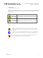
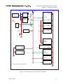
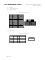
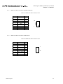
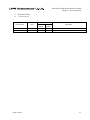
FEBL610Q793-02
ML610Q793 SDK BOARD
Hardware Manual
ML610Q793 Demo Kit
Issue Date: Jan.22.2015.
NOTES
No copying or reproduction of this document, in part or in whole, is permitted without the consent of LAPIS
Semiconductor Co., Ltd.
The content specified herein is subject to change for improvement without notice.
Examples of application circuits, circuit constants and any other information contained herein illustrate the
standard usage and operations of the Products. The peripheral conditions must be taken into account when
designing circuits for mass production.
Great care was taken in ensuring the accuracy of the information specified in this document. However, should you
incur any damage arising from any inaccuracy or misprint of such information, LAPIS Semiconductor shall bear
no responsibility for such damage.
The technical information specified herein is intended only to show the typical functions of and examples of
application circuits for the Products. LAPIS Semiconductor does not grant you, explicitly or implicitly, any license
to use or exercise intellectual property or other rights held by LAPIS Semiconductor and other parties. LAPIS
Semiconductor shall bear no responsibility whatsoever for any dispute arising from the use of such technical
information.
The Products specified in this document are intended to be used with general-use electronic equipment or devices
(such as audio visual equipment, office-automation equipment, communication devices, electronic appliances and
amusement devices).
The Products specified in this document are not designed to be radiation tolerant.
While LAPIS Semiconductor always makes efforts to enhance the quality and reliability of its Products, a Product
may fail or malfunction for a variety of reasons.
Please be sure to implement in your equipment using the Products safety measures to guard against the possibility
of physical injury, fire or any other damage caused in the event of the failure of any Product, such as derating,
redundancy, fire control and fail-safe designs. LAPIS Semiconductor shall bear no responsibility whatsoever for
your use of any Product outside of the prescribed scope or not in accordance with the instruction manual.
The Products are not designed or manufactured to be used with any equipment, device or system which requires an
extremely high level of reliability the failure or malfunction of which may result in a direct threat to human life or
create a risk of human injury (such as a medical instrument, transportation equipment, aerospace machinery,
nuclear-reactor controller, fuel-controller or other safety device). LAPIS Semiconductor shall bear no
responsibility in any way for use of any of the Products for the above special purposes. If a Product is intended to
be used for any such special purpose, please contact a ROHM sales representative before purchasing.
If you intend to export or ship overseas any Product or technology specified herein that may be controlled under
the Foreign Exchange and the Foreign Trade Law, you will be required to obtain a license or permit under the Law.
Copyright 2013-2015 LAPIS Semiconductor Co., Ltd.
2-4-8 Shinyokohama, Kouhoku-ku,
Yokohama 222-8575, Japan
http://www.lapis-semi.com/en/
Table of Contents
1. Read this First ........................................................................................................................1-1
1.1. Precaution for Safe and Proper Use ................................................................................................................. 1-1
1.2. Import Safety Notes ......................................................................................................................................... 1-2
1.3. Import Safety Notes ......................................................................................................................................... 1-3
1.4. Inquiry ............................................................................................................................................................ 1-3
2. General Description ..............................................................................................................2-1
2.1. Overview ......................................................................................................................................................... 2-1
2.2. Main Components............................................................................................................................................ 2-2
2.3. System Connection Examples ......................................................................................................................... 2-4
2.4. Block Diagram................................................................................................................................................. 2-5
3. Setting
.................................................................................................................................3-1
3.1. Setting operating mode of ML610Q793 SDK Board ...................................................................................... 3-1
3.1.1. Host IF switch ............................................................................................................................................ 3-1
3.1.2. UPDATE switch ........................................................................................................................................ 3-1
3.2. The switching of ML610Q793 SDK Board ..................................................................................................... 3-2
3.2.1. Reset switch ............................................................................................................................................... 3-2
4. Connectors .............................................................................................................................4-1
4.1. Connectors Pin Assignments ........................................................................................................................... 4-1
4.1.1. uEASE Connectors .................................................................................................................................... 4-1
4.1.2. SIO Connectors .......................................................................................................................................... 4-1
4.1.3. DEBUG IF Board Connectors (DEBUG IF Board) ................................................................................... 4-2
4.1.4. DEBUG IF Board Connectors (SDK Board) ............................................................................................. 4-2
5. Notes
................................................................................................................................5-1
5.1. Change about the setting hardware .................................................................................................................. 5-1
6. Revision History ....................................................................................................................6-1
6.1. Revision History ............................................................................................................................................. 6-1
Chapter 1
Read This First
This chapter explains the first things to do when the
user receives the ML610Q793 SDK Board.
Before turning on the power of the ML610Q793 SDK
Board, be sure to check that you understand the
contents of this chapter.
ML610Q793 SDK Board Hardware Manual
Chapter 1 Read this First
1.
Read this First
1.1.
Precaution for Safe and Proper Use
This manual uses various labels and icons that serve as your guides to operating this product safely and
properly so as to prevent death, personal injury, and property damage. The following table lists these labels
and their definitions.
Labels
Warning
This label indicates precautions that, if ignored or otherwise not
completely followed, could lead to death or serious personal injury.
Caution
This label indicates precautions that, if ignored or otherwise not
completely followed, could lead to personal injury or property
damage.
Icons
A triangular icon draws your attention to the presence of a hazard. The illustration inside
the triangular frame indicates the nature of the hazard—in this example, an electrical
shock hazard.
A circular icon with a solid background illustrates an action to be performed. The
illustration inside this circle indicates this action—in this example, unplugging the power
cord.
A circular icon with a crossbar indicates prohibition. The illustration inside this circle
indicates the prohibited action—in this example, disassembly.
FEBL610Q793
1-1
ML610Q793 SDK Board Hardware Manual
Chapter 1 Read this First
1.2.
Import Safety Notes
Please read this page before using the product.
Warning
Use only the specified voltage.
Using the wrong voltage risks fire or electrical shock.
At the first signs of smoke, an unusual smell, or other problems, unplug the ML610Q793 SDK
BOARD and disconnect all external power cords.
Continued use risks fire or electrical shock.
Do not use the product in an environment exposing it to moisture or high humidity.
Such exposure risks fire or electrical shock.
Do not pile objects on top of the product.
Such pressure risks fire or electrical shock.
At the first signs of breakdown, immediately stop using the product, unplug the ML610Q793 SDK
BOARD, and disconnect all external power cords.
Continued use risks fire or electrical shock.
Caution
Do not use this product on an unstable or inclined base as it can fall or overturn,
producing injury.
Do not use this product in an environment exposing it to temperatures outside the specified
range, direct sunlight, or excessive dust. Such factors risk fire and breakdown.
Do not use this product in an environment exposing it to excessive vibration, strong
electromagnetic fields, or corrosive gases. Such factors can loosen or even disconnect cable
connectors, producing a breakdown.
Use only the cables and other accessories provided. Using non-compatible parts
risks fire or breakdown.
Always observe the specified order for turning equipment on and off. Using the incorrect
order risks fire or breakdown.
Do not use the cables and other accessories provided with other systems.
Such improper usage risks fire.
Always turn off the power supplies before connecting or disconnecting the cables and
other accessories. Such improper handling risks fire or breakdown
FEBL610Q793
1-2
ML610Q793 SDK Board Hardware Manual
Chapter 1 Read this First
1.3.
Import Safety Notes
This manual utilizes the following notational conventions for convenience.
1.4.
[Note]
A “note” indicates a section of the manual that requires special attention.
[Reference]
A “reference” provides information related to the current topic and indicates
the page number of a related section of the manual.
[Execution example]
An “execution example” indicates an example related to the current topic.
(note x)
“(note x)” is a reference to a numbered note that provides supplementary
information lower on the same page.
[Note x]
“Note x” provides supplementary information related to the passage
marked with “(note x)”.
Inquiry
Thank you for purchasing the ML610Q793 SDK Board.
Please direct any questions or comments regarding this product to your LAPIS SEMICONDUCTOR
distributor or the nearest LAPIS SEMICONDUCTOR sales office.
FEBL610Q793
1-3
Chapter 2
General Description
This chapter gives a general description of the
ML610Q793 SDK Board.
ML610Q793 SDK Board Hardware Manual
Chapter 2 General Description
2.
2.1.
General Description
Overview
The ML610Q793 SDK Board is equipped with the sensor hub microcontroller “ML610Q793”, various sensors include
Accelerometer, Barometer and so on.
The ML610Q793 is a high-performance 8-bit low power microcontroller optimized for sensor hub, that integrates
LAPIS Semiconductor’s original high-performance 8-bit CPU core with a 16-bit multiplier/divider co-processor, 64
KByte flash memory, 4 KByte RAM, multiple interfaces for various sensors and host interfaces with 8 KByte logging
RAM in small footprint package. The ML610Q793 is an ideal sensor hub microcontroller for smart phone to separate
various sensors off from its application processor and control them effectively for reducing total system power
consumption.
In using the ML610Q793 SDK Board, also refer to the following document:
• ML610Q793 User’s Manual
FEBL610Q793
2-1
ML610Q793 SDK Board Hardware Manual
Chapter 2 General Description
2.2.
Main Components
ML610Q793 SDK is consisted two boards for the sensor hub microcontroller SDK Board and DEBUG IF Board.
Figure 2-1 to Figure 2-2 show the top and bottom views of the ML610Q793 SDK Board and Table 2-1 to
Table 2-2 lists the main components of the board.
[1]
[7]
[2]
[8]
[3]
[4]
[9]
[5]
[10]
[6]*1
[11]
Top view
[14]*1
[12]
[15] *1
[16]
[13]
Back view
Figure 2-1 sensor hub microcontroller SDK Board
FEBL610Q793
2-2
ML610Q793 SDK Board Hardware Manual
Chapter 2 General Description
Table 2-1 Components Mounted on sensor hub microcontroller SDK Board
[2]
[3]
[4]
[5]
[6]
[7]
[8]
[9]
[10]
Name
Optical Proximity Sensor and
Ambient Light Sensor
3-Axis Digital Accelerometer
3-Axis Digital Accelerometer
Hall IC
ML610Q793
UV sensor
Humidity and Temperature Sensor
HOST IF switch
UPDATE switch
Reset switch
[11]
HOST IF Jumper connector
[12]
[13]
[14]
DEBUG IF Board connector
USB connector
Magnetic Sensor
[15]
3-Axis Gyroscope
[16]
Digital Barometer
[1]
Description
Optical Proximity Sensor and Ambient Light Sensor
(BH1772GLC made by ROHM )
3-Axis Digital Accelerometer (KXTF9 made by Kionix)
3-Axis Digital Accelerometer (BMA250E made by BOSH)
Hall IC (BU52061NVX made by ROHM)
Sensor hub microcontroller
*1
UV sensor (ML8511HA made by LAPIS)
Humidity and Temperature Sensor (SHT20 made by SENSIRION)
Switch for selecting the mode of HOST IF
Firmware update switch
Reset switch for ML610Q793
Setting to use the host of SDK.
IF use the other host, remove this connector from pins.
In the detail, see “circuit diagram of SDK Board”.
DEBUG IF Board/10 pins FFC cable connector
Supply Voltage for Board from USB mini B connector
*1
Magnetic Sensor (AK8975B made by AsahiKASEI Elec)
3-Axis Gyroscope
*1
(L3G4200D made by STMicro or KGY13 made by Kionix)
Digital Barometer (BMP280 made by BOSH)
*1 This sensor is not implemented.
[2]
[1]
[3]
Top View
Back View
Figure 2-2 DEBUG IF Board
Table 2-2 Components Mounted on DEBUG IF Board
Number
Name
Description
1
DEBUG IF Board connector
SDK Board /10 pins FFC cable connector
2
SIO connector
UART interface connector
3
uEASE connector
uEASE connector
FEBL610Q793
2-3
ML610Q793 SDK Board Hardware Manual
Chapter 2 General Description
2.3.
System Connection Examples
Figure 2-3 show examples of ML610Q793 SDK Board power supply connections.
Reset switch
µEASE connector
Oscillator
FFC connector
Reguretor
SIO connector
FFC
Any sensor
ML610Q793
DEBUG IF Board
RS232C
Convertor
Sensor Hub Microcontroller
SDK Board
PC
USB VBUS
µEASE
Figure 2-3 System connection example
FEBL610Q793
2-4
ML610Q793 SDK Board Hardware Manual
Chapter 2 General Description
2.4.
Block Diagram
Figure 2-4 is a block diagram of the ML610Q793 and Figure 2-5 to Figure 2-7 is a block diagram SDK
Board.
DVDD
DGND
AVDD
AGND
VDDL
*1
*1
PA0_EXI00 , PA1_EXI01 ,
*1
*1
PA2_EXI02 , PA3_EXI03 ,
*1
*1
PA4_EXI04 , PA5_EXI05 ,
*1
*1
PA6_EXI06 , PA7_EXI07 ,
*1
*1
PB0_EXI08 , PB1_EXI09 ,
*1
*1
PB2_EXI10 , PB3_EXI11 ,
*1
*1
PB4_EXI12 , PB5_EXI13 ,
*1
*1
PB6_EXI14 , PB7_EXI15
*1
*1
PA0_EXI00 , PA1_EXI01 ,
*1
*1
PA2_EXI02 , PA3_EXI03 ,
*1
*1
PA4_EXI04 , PA5_EXI05 ,
*1
*1
PA6_EXI06 , PA7_EXI07 ,
*1
*1
PB0_EXI08 , PB1_EXI09 ,
*1
*1
PB2_EXI10 , PB3_EXI11 ,
*1
*1
PB4_EXI12 , PB5_EXI13 ,
*1
*1
PB6_EXI14 , PB7_EXI15
*2
PC0_INT_S , PC1,
*3
*3
PC2_RXD0 , PC3_TXD0 ,
PC4
XT
PB3_EXI11
RESET_N
*
VDDX 4
*
XTN 4
*1
*2
*3
*4
CPU
(uX-U8/100)
Program
Memory
(Flash) 64KB
Coprocessor
HOST IF
(RAM8KB)
(SPI / I2C)
RAM 4KB
Interrupt
Controller
SPI (Master)
General-purpose
I/O Port
8-bit 2ch
5-bit 1ch
I2C (Master)
Successive
ADC
12-bit 3ch
Timer
8-bit 6ch
Arithmetic Circuit
I2C_SPISEL
SDO_SDA_S
SDI_SA1_S
SCS_SA0_S
SCLK_SCL_S
*2
PC0_INT_S
SDO_M
SDI_M
SCS_M
SCLK_M
SDA_M
SCL_M
ADC_IN0
ADC_IN1
ADC_IN2
VREF
Asynchronous
SIO 1ch
PC2_RXD0
*3
PC3_TXD0
UART 1ch
PB6_EXI14
*3
PB7_EXI15
*3
WDT
Clock
Controller
Reset
Controller
*3
On Chip
ICE
PLL
Test
*4
VPP
TEST1
TEST0
Shared by the interrupt pins and the general-purpose I/O port
Shared by the interrupt output pin of the host interface and the general-purpose I/O port
Shared by the UART/Asynchronous SIO transmit/receive pins and the general-purpose I/O port
Leave this pin open in ML610Q793
Figure 2-4 the block diagram of ML610Q793
FEBL610Q793
2-5
ML610Q793 SDK Board Hardware Manual
Chapter 2 General Description
ML610Q793 SDK Board
OSC1
ML610Q793
OSC2
XT
UPDATE
switch
Reset switch
ADC(3)
DVDD
TEST0
DEBUG IF Board connector
HSTIF
RESET(1)
TEST1
USB
+FT232H
HOSTIF(4)
I2C0_M(2)
SDA_M
I2C
INT
SCL_M
SPI_M(4)
PC2_RXD0
PC3_TXD0
HOST IF
switch
SPI
INT1
DRDY
SDO_M
SDI_M
SCS_M
SCLK_M
I2C
INT
IO Port (21)
3-Axis
Digital Accelerometer
3-Axis Gyroscope *1
3-Axis
Digital Accelerometer
DVDD
GND
I2C_SPISEL
I2C
DRDY
Magnetic Sensor *1
I2C Optical Proximity Sensor and
INT Ambient Light Sensor
I2C
*1 This sensor is not implemented.
LED
Digital Barometer
PIO
I2C0_M
SPI_M
I2C Humidity and Temperature Sensor
OUT
Hall IC
OUT
UV sensor *1
Figure 2-5 the block diagram (1) of ML610Q793 SDK Board
FEBL610Q793
2-6
ML610Q793 SDK Board Hardware Manual
Chapter 2 General Description
D50V
D18V
REGU1
USB
connector
AVDD
DVDD
ML610Q793
AGND
Vo:1.8V
Io:150mA
D28V
REGU2
Vo:2.8V
Io:150mA
GND
HST
IF
AGND
DVDD
AVDD DGND
BMA250E
VDD、VDDIO
FPC
DGND
KXTF9
VDD、VDDIO
AK8975B (*)
VDD
VDDIO
ML8511HA (*)
VDD
BU52061NVX
VDD
L4G4200D or KGY13 (*)
VDD、VDDIO
BMP280
VDD
VDDIO
SHT20
VDD
BH1772GLC
VDD
(*) This sensor is not implemented.
Figure 2-6 the block diagram (2) of ML610Q793 SDK Board
FEBL610Q793
2-7
ML610Q793 SDK Board Hardware Manual
Chapter 2 General Description
TEST0
TEST1
RXD
TXD
Level
Shifter
PC2_RXD0
DEBUG IF Board connector
SIO connector
uEASE connector
DEBUG IF Board
PC3 TXD0
Figure 2-7 the block diagram of ML610Q793 SDK Board (DEBUG IF Board)
FEBL610Q793
2-8
Chapter 3
Setting
This chapter gives a Setting opreating mode of the
ML610Q793 SDK Board.
ML610Q793 SDK Board Hardware Manual
Chapter 3 Setting
3.
Setting
3.1.
3.1.1.
Setting operating mode of ML610Q793 SDK Board
Host IF switch
ML610Q793 SDK Board enables switching the interface of host processor and microcontroller by the
Host IF switch is integrated on SDK Board.
Figure 3-1 shows the Host IF switch, Table 3-1 lists the switch setting.
SW3
3
2
1
Figure 3-1 the Host IF switch
Table 3-1 the Host IF switch
Setting
1-2
2–3
3.1.2.
Explanation
The interface of host processor and microcontroller is “I2C”.
The interface of host processor and microcontroller is “SPI”. (initial value)
UPDATE switch
ML610Q793 SDK Board realizes the function of firmware update for microcontroller by the UPDATE
switch is integrated on SDK Board.
Figure 3-2 shows the UPDATE switch, Table 3-2 lists the switch setting.
SW2
3
2
1
Figure 3-2 the UPDATE switch
Table 3-2 the UPDATE switch
Setting
1–2
2–3
FEBL610Q793
Explanation
“DVDD” is applied to the TEST0 pin for firmware update.
The TEST0 pin connects to uEASE connector for operating normal mode and
connecting to the debugger. (initial value)
3-1
ML610Q793 SDK Board Hardware Manual
Chapter 3 Setting
3.2. The switching of ML610Q793 SDK Board
3.2.1. Reset switch
This is the RESETN pin of ML610Q793. Pressing this switch configures the CPU core and the peripheral
IO circuitry as a “Reset” is assertion.
[Note]
Cutting off the connecting to the debugger when “Reset” is assertion during connects to debugger.
Assert “Reset” from the debugger during debug.
Figure 3-3 the Reset switch
FEBL610Q793
3-2
Chapter 4
Connectors
This chapter describes the connectors mounted on the
ML610Q793 SDK Board.
ML610Q793 SDK Board Hardware Manual
Chapter 4 Connectors
4.
Connectors
4.1.
4.1.1.
Connectors Pin Assignments
uEASE Connectors
Table 4-1 uEASE connector Pins
Pin No.
1
2
3
4
5
6
7
8
9
10
11
12
13
14
4.1.2.
Signal name
VTref
GND
Vpp
GND
RESET_N
GND
TEST0
GND
VDDL
GND
N.C.
GND
UVDD_O
TESTMODE
I/O
O
I
I
I/O
I
I
O
Destination
DVDD
GND
test1
test0
GND
GND
GND
-
13
14
1
2
SIO Connectors
Table 4-2 SIO connector Pins
I/O
Destination
5V
-
D50V
2
TXD
O
PC3_TXD0
3
RXD
I
PC2_RXD0
4
GND
-
GND
Pin No.
Signal name
1
FEBL610Q793
4
1
4-1
ML610Q793 SDK Board Hardware Manual
Chapter 4 Connectors
4.1.3.
DEBUG IF Board Connectors (DEBUG IF Board)
Table 4-3 DEBUG IF Board connector Pins
Pin No.
1
2
3
4
5
6
7
8
9
10
4.1.4.
Signal name
D50V
DVDD
DVDD
TEST0
TEST1
OPEN
TXD
RXD
GND
GND
I/O
I/O
I/O
I
O
-
10
1
DEBUG IF Board Connectors (SDK Board)
Table 4-4 DEBUG IF Board connector Pins
Pin No.
10
9
8
7
6
5
4
3
2
1
FEBL610Q793
Signal name
D50V
DVDD
DVDD
TEST0
TEST1
OPEN
PC3_TXD0
PC2_RXD0
GND
GND
I/O
I/O
I/O
O
I
-
1
10
4-2
Chapter 5
Notes
This chapter describes the Notice when ML610Q793
SDK Board is used.
5.
5.1.
Notes
Change about the setting hardware
IF when change setting of the switch and so on, Always turn off the power supplies to avoid malfunction
and breakdown.
FEBL610Q793
5-1
Chapter 6
Revision History
ML610Q793 SDK Board Hardware Manual
Chapter 6 Revision History
6.
6.1.
Revision History
Revision History
Document No.
Date
FEBL610Q793-01
FEBL610Q793-02
Jun. 12, 2013
Jan. 22, 2015
FEBL610Q793
Page
Previous
Current
Edition
Edition
–
–
–
–
Description
Final edition issued
Minor error correction
6-1