1
• SAFETY PRECAUTIONS •
(Be sure to read before use)
Before using this product, read through this manual and the relevant ones introduced in this manual to
handle the product correctly and safely.
The following instructions are limited to the CC-Link/LT master module only. For safety precautions on
the programmable controller system, refer to the user’s manual of the CPU module to be used.
In this manual, the levels of hazardous situations are shown as follows:
DANGER
Indicates that incorrect handling may cause hazardous conditions,
resulting in death or severe injury.
! CAUTION
Indicates that incorrect handling may cause hazardous conditions,
resulting in medium or slight personal injury or physical damage.
!
Note that even a ! CAUTION leveled situation may lead to a serious consequence. Be sure to follow
the instructions of both levels.
Keep this manual in a handy place and make sure to deliver this to the end user.
[Design Precautions]
!
DANGER
• When the data link communication is faulty, refer to Chapter 6 of this manual for operating states
of each station.
• When connecting peripheral devices to the CPU module, create interlock circuits in the
sequence programs so that the safety of the whole system will be ensured.
Before modifying programs, changing operating status (status control) or conducting other
controls with the programmable controller running, thoroughly read the relevant manuals and
confirm the safety. Especially when instructing these controls from external devices to a remote
programmable controller, problems arisen on the programmable controller may not be solved
immediately due to abnormal data communications.
To prevent this, create interlock circuits in the sequence programs and set the corrective
measures between the external devices and the programmable controller CPU in case of
abnormal data communication.
• Do not write data to “Prohibited area” of the buffer memory.
Doing so may lead to malfunction of the programmable controller system.
!
CAUTION
• Do not bring the control wires and communication cables close to the main circuit or power
wires.
Keep a distance of at least 100mm between them.
Failure to do so may cause malfunctions due to noise.
A-1
A-1
[Installation Precautions]
!
CAUTION
• Use the programmable controller system in the operating environment that meets the general
specifications of this manual.
Using in any other environment may cause electric shocks, fires, malfunctions, or damage or
deterioration of the product.
• While pressing the installation lever located at the bottom of module, insert the module fixing tab
into the fixing hole in the base unit until it stops. Then, securely mount the module with the fixing
hole as a supporting point.
Incorrect installation may cause malfunctions, fault or drop of the module.
When using the module in an environment where constant vibrations may occur, secure it with
screws. Tighten the screws within the specified torque range.
Loose tightening may cause a drop of the module, a short circuit or malfunctions.
Excessive tightening may cause the same as the above due to damage to the screws or the
module.
• Be sure to shut off all phases of the external power supply used by the system before mounting
or dismounting the module.
Failure to do so may damage the product.
• Do not directly touch the conducting parts and electronic parts of the module.
Doing so may cause a malfunction or a fault of the module.
[Wiring Precautions]
!
CAUTION
• Carefully prevent foreign matter such as chaff and wire chips from entering the inside of the
module.
They may cause a fire, fault or malfunction.
• The module has an ingress prevention label on its top to prevent foreign matter, such as wire
offcuts, from entering the module during wiring.
Do not peel this label during wiring.
Before starting system operation, be sure to peel this label because of heat dissipation.
• For the CC-Link/LT, use the cables specified by the CC-Link Partner Association.
The performance of the CC-Link/LT cannot be assured if any other cables than the specified are
used.
Also, observe the network wiring specifications given in Chapter 3.
Normal data communication is not guaranteed if the wiring is not conducted according to the
specifications.
• Place the communication cables or power cables for the module in a duct or to fasten them with
clamps.
If not, the dangling condition, shift or inadvertent pulling of the cables may lead to damage to the
module or cables, or a malfunction due to faulty cable connection.
A-2
A-2
[Wiring Precautions]
!
CAUTION
• When disconnecting a communication cable or power cable from the module, do not hold and
pull the cable portion by hand.
For the cable with a connector, hold the connector connected to the module with a hand and pull
it out.
For the cable connected to a terminal block, loosen the screws on the terminal block and
disconnect the cable.
Pulling the cable with it connected to the module may result in malfunctions or damage to the
module and/or cables.
[Precautions on Activation/Maintenance]
!
CAUTION
• Do not disassemble or modify the module.
Doing so may cause a fault, malfunction, injury or fire.
• Be sure to shut off all phases of the external power supply used by the system before mounting
or dismounting the module.
Failure to do so may cause a fault or malfunction of the module.
• Do not touch any terminal while the power is on. Doing so may cause malfunctions.
• Be sure to shut off all phases of the external power supply used by the system before cleaning
the module or retightening the terminal screws or module installation screws.
Failure to do so may cause a fault or malfunction of the module.
Loose tightening may cause a drop of the module, a short circuit or malfunctions.
Excessive tightening may cause the same as the above due to damage to the screws or the
module.
• Do not mount/remove the module to/from the base unit or terminal block more than 50 times
(IEC 61131-2 compliant), after the first use of the product.
Failure to do so may cause module malfunctions.
• Before handling the module, always touch grounded metal, etc. to discharge static electricity
from the human body.
Failure to do so can cause the module to fail or malfunction.
[Precautions on Disposal]
!
CAUTION
• When disposing of this product, treat it as industrial waste.
A-3
A-3
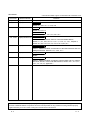
REVISIONS
* The manual number is given on the bottom left of the back cover.
Print Date
* Manual Number
Revision
Sep., 2002 SH(NA)-080351E-A First printing
Feb., 2003 SH(NA)-080351E-B Correction
Section 2.1, 2.2.2, 3.1.1, 4.5.2, 6.6
Mar., 2004 SH(NA)-080351E-C
Addition
Section 4.5.2, 4.5.3
Partial correction
Section 1.2, 3.1, 4.1, 4.2.3, 4.5, 4.5.4, 6.7
Jan., 2005
SH(NA)-080351E-D
Partial correction
SAFETY PRECAUTIONS, Generic Terms and Abbreviations,
Section 1.1, 2.1, 2.2.2, 2.2.3, 3.1, 3.1.1, 3.3.2, 4.1, 4.2.1, Chapter 5,
Section 6.2, 6.3.1 to 6.3.4, 6.4, 6.4.1 to 6.4.5, 6.6, 6.7
Mar., 2006 SH(NA)-080351E-E
Partial correction
SAFETY PRECAUTIONS, Conformation to the EMC Directive and Low
Voltage Instruction, Section 2.2.1, 2.2.2, 3.1.1
Nov., 2006 SH(NA)-080351E-F
Partial correction
INDEX
Oct., 2008 SH(NA)-080351E-G
Partial correction
SAFETY PRECAUTIONS, Compliance with the EMC and Low Voltage
Directives, Generic Terms and Abbreviations, Section 2.2.1, 2.2.3, 4.1,
4.2.1, 4.3, 4.5, 6.7, Appendix 1
Japanese Manual Version SH-080344-H
This manual confers no industrial property rights or any rights of any other kind, nor does it confer any patent
licenses. Mitsubishi Electric Corporation cannot be held responsible for any problems involving industrial property
rights which may occur as a result of using the contents noted in this manual.
© 2002 MITSUBISHI ELECTRIC CORPORATION
A-4
A-4
INTRODUCTION
Thank you for purchasing the MELSEC-Q series programmable controller. Before using the product, read
this manual carefully to fully understand the functions and the performance of the programmable controller.
Please forward a copy of this manual to the end user.
CONTENTS
SAFETY PRECAUTIONS..............................................................................................................................AREVISIONS ....................................................................................................................................................AINTRODUCTION............................................................................................................................................ACompliance with the EMC and Low Voltage Directives................................................................................AGeneric Terms and Abbreviations .................................................................................................................APacking List ....................................................................................................................................................A-
1. OVERVIEW
1
4
5
8
8
9
1- 1 to 1- 3
1.1 Overview................................................................................................................................................... 1- 1
1.2 Features ................................................................................................................................................... 1- 2
2. SYSTEM CONFIGURATION
2- 1 to 2- 10
2.1 Overall Configuration ............................................................................................................................... 22.2 Applicable System.................................................................................................................................... 22.2.1 Applicable Modules and Numbers of Available Modules ................................................................ 22.2.2 Notes on System Configuration........................................................................................................ 22.2.3 Confirmation of Function Version ..................................................................................................... 2-
3. SPECIFICATIONS
1
2
2
5
9
3- 1 to 3-16
3.1 Performance Specifications ..................................................................................................................... 3- 1
3.1.1 Network Wiring Specifications .......................................................................................................... 3- 2
3.2 I/O Signals to/from Programmable Controller CPU ................................................................................ 3- 4
3.2.1 I/O Signals in 4-Point Mode Setting.................................................................................................. 3- 4
3.2.2 I/O Signals in 8-Point Mode Setting.................................................................................................. 3- 5
3.2.3 I/O Signals in 16-Point Mode Setting................................................................................................ 3- 5
3.3 Buffer Memory.......................................................................................................................................... 3- 6
3.3.1 List of Buffer Memory ........................................................................................................................ 3- 6
3.3.2 Details of Buffer Memory .................................................................................................................. 3- 6
3.4 Concept of Control Point (Point Mode Setting and I/O Point Setting).................................................... 3-10
3.4.1 Simplified Setting............................................................................................................................... 3-10
3.4.2 Advanced Setting .............................................................................................................................. 3-10
3.5 Concept of Last Station Number Setting................................................................................................. 3-13
3.6 Condition of Each Station in Case of Failure .......................................................................................... 3-13
3.7 Data Link Processing Time...................................................................................................................... 3-14
3.7.1 Link Scan Time.................................................................................................................................. 3-14
3.7.2 Transmission Delay Time ................................................................................................................. 3-15
A-5
A-5
4. PREPARATORY PROCEDURES FOR DATA LINK
4- 1 to 4-19
4.1 Procedures for Data Link ......................................................................................................................... 4- 1
4.2 Installation ................................................................................................................................................ 4- 3
4.2.1 Handling Precautions ........................................................................................................................ 4- 3
4.2.2 Installation Environment.................................................................................................................... 4- 3
4.2.3 Cables, Connectors and Terminating Resistors .............................................................................. 4- 3
4.3 Name of Parts and Setting....................................................................................................................... 4- 4
4.4 Switch Setting of Intelligent Function Module ......................................................................................... 4- 6
4.5 Connecting Modules with Cables ............................................................................................................ 4- 8
4.5.1 How to Connect Connector for Dedicated Flat Cable...................................................................... 4- 9
4.5.2 How to Connect VCTF or High Flexible Cable Connector .............................................................. 4-11
4.5.3 Mixture of Different Kinds of Cables ................................................................................................. 4-14
4.5.4 Installing Terminating Resistors........................................................................................................ 4-17
4.5.5 Check of Wiring ................................................................................................................................. 4-18
4.6 Installing/Removing Remote Station ....................................................................................................... 4-19
5. PROGRAMMING
5- 1 to 5- 2
5.1 System Configuration............................................................................................................................... 5- 1
5.2 Devices Available for Users..................................................................................................................... 5- 2
5.3 Program Example .................................................................................................................................... 5- 2
6. TROUBLESHOOTING
6- 1 to 6-18
6.1 Condition of Each Station in Case of Failure .......................................................................................... 6- 1
6.2 Troubleshooting Flow............................................................................................................................... 6- 2
6.3 Troubleshooting of Master Station........................................................................................................... 6- 3
6.3.1 When "RUN" LED Goes Off.............................................................................................................. 6- 3
6.3.2 When "L RUN" LED Goes Off........................................................................................................... 6- 4
6.3.3 When "ERR." LED Lights Up or Blinks............................................................................................. 6- 5
6.3.4 When "L ERR." LED Lights Up or Blinks.......................................................................................... 6- 6
6.4 Troubleshooting of Remote I/O Station(s)............................................................................................... 6- 7
6.4.1 When "PW" LED Goes Off................................................................................................................ 6- 7
6.4.2 When "L RUN" LED Goes Off........................................................................................................... 6- 8
6.4.3 When "L ERR." LED Lights Up ......................................................................................................... 6- 9
6.4.4 When Input From Remote I/O Station Is Not Possible .................................................................... 6-10
6.4.5 When Output From Remote I/O Station Is Not Possible ................................................................. 6-11
6.5 Error Codes .............................................................................................................................................. 6-12
6.6 CC-Link/LT Diagnostics Using GX Developer ........................................................................................ 6-13
6.7 Check of Module Condition (Self-loopback Test) ................................................................................... 6-18
A-6
A-6
APPENDIX
App- 1 to App- 4
Appendix 1 External Dimensions...............................................................................................................AppAppendix 2 I/O Assignment Sheet.............................................................................................................AppAppendix 2.1 I/O Assignment Sheet for 4-Point Mode Setting............................................................AppAppendix 2.2 I/O Assignment Sheet for 8-Point Mode Setting............................................................AppAppendix 2.3 I/O Assignment Sheet for 16-Point Mode Setting..........................................................AppINDEX
A-7
1
2
2
3
4
Index- 1 to Index- 2
A-7
Compliance with the EMC and Low Voltage Directives
(1) For programmable controller system
To configure a system meeting the requirements of the EMC and Low Voltage Directives when
incorporating the Mitsubishi programmable controller (EMC and Low Voltage Directives
compliant) into other machinery or equipment, refer to Chapter 9 "EMC AND LOW VOLTAGE
DIRECTIVES" of the QCPU User's Manual (Hardware Design, Maintenance and Inspection).
The CE mark, indicating compliance with the EMC and Low Voltage Directives, is printed on the
rating plate of the programmable controller.
(2) For the product
No additional measures are necessary for the compliance of this product with the EMC and Low
Voltage Directives.
Generic Terms and Abbreviations
This manual uses the following generic terms and abbreviations except for the case where precise
specification is required.
Generic Term/Abbreviation
Description
QJ61CL12
Indicates QJ61CL12 type CC-Link/LT master module
Master station
Station that controls data link system. One master station is required for each system.
Remote I/O station
Remote station that handles bit information only. (Inputs/outputs data to/from external
devices) (CL2X8-D1B2, CL2Y8-TP1B2, etc.)
Remote device station
Remote station that handles bit unit and word unit data only. (Performs input and
output with external devices, and analog data conversion.)
Remote station
Generic term for remote I/O station and remote device station.
Controlled by the master station.
Master module
Module that controls the data link system.
One master module is required for each system.
Remote I/O module
Remote module that handles bit unit data only. (Performs input and output with
external devices.)
Remote device module
Remote module that handles bit unit and word unit data only. (Performs input and
output with external devices, and analog data conversion.)
Remote module
Generic term for remote I/O module and remote device module.
Programmable controller CPU
Generic term for Q00JCPU, Q00CPU, Q01CPU, Q02CPU, Q02HCPU, Q06HCPU,
Q12HCPU, Q25HCPU, Q02PHCPU, Q06PHCPU, Q12PHCPU, Q25PHCPU,
Q12PRHCPU, Q25PRHCPU, Q02UCPU, Q03UDCPU, Q04UDHCPU, Q06UDHCPU,
Q13UDHCPU, Q26UDHCPU, Q03UDECPU, Q04UDEHCPU, Q06UDEHCPU,
Q13UDEHCPU, Q26UDEHCPU.
C Controller module
Generic term for the Q06CCPU-V, Q06CCPU-V-B.
GX Developer
Generic product name for SWnD5C-GPPW-E, SWnD5C-GPPW-EA, SWnD5C-GPPWEV, and SWnD5C-GPPW-EVA. ("n" means version 4 or later.)
"-A" and "-V" mean "volume license product" and "version-upgrade product"
respectively.
Intelligent function module
Q series module other than CPU, power supply and I/O modules, which are to be
mounted on base unit
Dedicated power supply
Power supply adapter
A-8
Module connected for power supply to CC-Link/LT system. At least one power supply
adapter is required for a system.
A-8
Packing List
The packing list of QJ61CL12 is as shown below.
Item name
QJ61CL12 CC-Link/LT master module
A-9
Quantity
1
A-9
1 OVERVIEW
MELSEC-Q
1 OVERVIEW
1
This manual describes about the QJ61CL12 type CC-Link/LT Master Module
(hereinafter shown as QJ61CL12), including its specifications, names of the parts and
the setting. The QJ61CL12 is designed for the use in combination with the MELSECQ series programmable controller CPU.
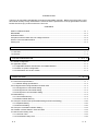
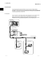
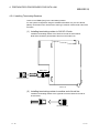
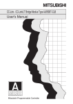
1.1 Overview
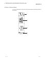
The CC-Link/LT is a line-saving network system designed for the use inside control
boxes or devices, and you will be free from complicated or incorrect wiring.
Wiring among sensors, actuators and controllers can be easily saved and excellent
performance such as high-speeded response time can be realized by this.
CC-Link/LT
Master Module
QJ61CL12
Terminating Resistor
Power Supply Adapter
CL1PAD
1
General Power Supply
24V DC
Terminating Resistor
Partner
Company's
Product
Remote Module
CL1Y4-T1B2
CL2AD4-B
Y0
1-1
1-1
1 OVERVIEW
MELSEC-Q
1.2 Features
1
The CC-Link/LT features the following:
(1) Easy connection/disconnection of communication cable
Because a dedicated connector enables simple connection/disconnection of the
communication cables, modules can be easily added and/or replaced.
Using dedicated flat cables, VCTF cables and/or high flexible cables will
decrease the wiring steps and save the cost of the cables.
(2) No parameter settings
To operate the CC-Link/LT system, no parameters are required to be set.
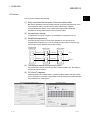
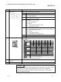
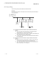
(3) Simplified programming
Since link devices of the CC-Link/LT are allocated to X/Y devices of the
programmable controller CPU, you can create programs with X/Y devices only
and not have to pay attention to the entire network.
Programmable
controller CPU
X
Y
Master station
Refresh of X
Refresh of Y
X
Y
Remote station
Link scan
Link scan
X
Input
Y
Output
(4) Transmission speed auto-tracking function
The transmission speed should be set on the master module only. No setting is
required for remote stations.
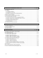
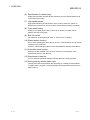
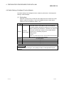
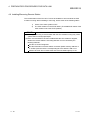
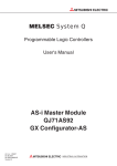
(5) CC-Link/LT diagnosis
Operating state of the master station, presence of faulty station and other states
can be checked by CC-Link/LT diagnostics of the GX Developer and this enables
easy maintenance of the system.
<Line Monitor [Host station] screen>
1-2
<Loop test screen>
1-2
1 OVERVIEW
MELSEC-Q
(6) Specification of refresh range
Setting the last station number will stop refreshing for unconnected stations and
reduce the link scan time.
(7) High speed refresh
High speed refreshing of 256 points for 0.5 ms can be achieved. (When 16
modules are connected in 16-point mode at a transmission speed of 2.5 Mbps)
(8) Point mode setting
Setting of “occupied points” and “numbers of I/O points” per station allows
effective use of the I/O points.
(9) Bulk I/O control
The maximum of 2048 points (X: 1024; Y: 1024) can be controlled.
(10) Station detach function
Even if some module goes down due to an error, communications among normal
modules can be continued.
However, cable breakage of the trunk line will disable the data link of all stations.
(11) Automatic return function
When the module isolated due to an error recovers its normal state, it will
automatically return to the data link.
(12) Stop/restart of data link
You can stop and restart the module while the data link is being executed.
(13) Storing data by remote station type
Through the initial communication after powering on or adding a remote station,
occupied points, I/O types or other information will be detected and stored in the
buffer memory.
1-3
1-3
2 SYSTEM CONFIGURATION
MELSEC-Q
2 SYSTEM CONFIGURATION
This section mainly describes the system configuration of the CC-Link/LT.
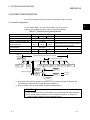
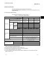
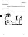
2.1 Overall Configuration
2
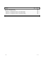
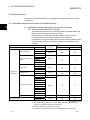
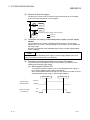
To one master station, up to 64 remote stations can be connected.
However, the conditions shown in Table 2.1 should be satisfied.
Table 2.1 Network Wiring Specifications
Item
Specifications
Transmission speed
2.5 Mbps
625 kbps
Distance between stations
Not limited
Max. no. of modules per drop line
8 modules
Length of trunk line
35 m
T-branch interval
100 m
Remarks
156kbps
500 m
Cable length between terminating resistors.
Length of drop lines not included
Not limited
Max. length of drop line
4m
16 m
60 m
Max. cable length for one branch line
Overall length of drop lines
15 m
50 m
200 m
Total length of all drop lines
T-branch
connection
Length of trunk line (Drop line not included)
Master station
Interval length of T-branch
Length
of
*3
drop
Terminating line
resistor
Power
supply
adapter
*1
Length of drop line
Remote
station
Remote
station
*2
Remote
station
Remote
station
Remote
station
*3
Terminating
resistor
Remote
station
Remote
station
Distance
between stations
Remote
station
Remote
station
Trunk line
Drop line
Remote
station
*1: The length of the drop line includes the length of *2. (The maximum length of drop line and
overall length of drop lines also include the length marked *2.)
*3: Refer to Section 4.5.4 for the terminating resistor installing method.
POINT
(1) The connection order of remote stations is not related with the station numbers.
(2) The remote station numbers are not necessarily consecutive. (Leaving any
station number out does not cause data link failure.)
2-1
2-1
2 SYSTEM CONFIGURATION
MELSEC-Q
2.2 Applicable System
This section provides information on the available CPU module and notes on system
configuration.
2.2.1 Applicable Modules and Numbers of Available Modules
2
(1) Applicable modules and base units, and No. of modules
(a) When mounted with a CPU module
The table below shows the CPU modules and base units applicable to the
QJ61CL12 and quantities for each CPU model.
Depending on the combination with other modules or the number of
mounted modules, power supply capacity may be insufficient.
Pay attention to the power supply capacity before mounting modules, and if
the power supply capacity is insufficient, change the combination of the
modules.
Applicable CPU module
CPU type
CPU model
Q00JCPU
Basic model QCPU
Q00CPU
Q01CPU
No. of
modules(*1)
Base unit(*2)
Main base unit
Extension base unit
Up to 16
Up to 24
Q02CPU
High Performance model
QCPU
Q02HCPU
Q06HCPU
Up to 64
Q12HCPU
Q25HCPU
Q02PHCPU
Process CPU
Q06PHCPU
Q12PHCPU
Up to 64
Q25PHCPU
Programmable
controller CPU
Redundant CPU
Q12PRHCPU
Q25PRHCPU
Q02UCPU
Up to 53
Up to 36
Q03UDCPU
Q04UDHCPU
Q06UDHCPU
Q13UDHCPU
Universal model QCPU
Q26UDHCPU
Q03UDECPU
Up to 64
Q04UDEHCPU
Q06UDEHCPU
Q13UDEHCPU
Q26UDEHCPU
Safety CPU
C Controller module
QS001CPU
Q06CCPU-V
Q06CCPU-V-B
N/A
(*3)
Up to 64
: Applicable, : N/A
*1: The number varies depending on the I/O points of the CPU module and the
number of occupied I/O points set in QJ61CL12.
*2: Can be installed to any I/O slot of a base unit.
*3: Connection of extension base units is not available with any safety CPU.
2-2
2-2
2 SYSTEM CONFIGURATION
MELSEC-Q
REMARK
For use of a C Controller module, refer to the C Controller Module User’s Manual.
(b) Mounting to a MELSECNET/H remote I/O station
The table below shows the network modules and base units applicable to
the QJ61CL12 and quantities for each network module model.
Depending on the combination with other modules or the number of
mounted modules, power supply capacity may be insufficient.
Pay attention to the power supply capacity before mounting modules, and if
the power supply capacity is insufficient, change the combination of the
modules.
Applicable CPU
module
No. of modules(*2)
No. of modules(*1)
Main base unit of
Extension base unit
remote I/O station
of remote I/O station
QJ72LP25-25
QJ72LP25G
QJ72LP25GE
Up to 64
QJ72BR15
: Applicable,
: N/A
*1: Limited within the range of I/O points for the network module.
*2: Can be installed to any I/O slot of a base unit.
REMARK
The Basic model QCPU or C Controller module cannot create the MELSECNET/ H
remote I/O network.
(2) Application to multiple CPU system
When applying the QJ61CL12 to a multiple CPU system, see the QCPU User’s
Manual (Multiple CPU System) in advance.
(a) QJ61CL12 available for multiple CPU system
The function version of the first released QJ61CL12 is B, and it supports
multiple CPU systems.
(b) Parameters of intelligent function modules
Write the parameters of intelligent function modules to only the control CPU
of QJ61CL12.
2-3
2-3
2 SYSTEM CONFIGURATION
MELSEC-Q
(4) Applicable software package
The systems and software packages available for the QJ61CL12 are shown
below.
When using the QJ61CL12, GX Developer is indispensable.
Software version
GX Developer
Q00J/Q00/Q01CPU
Q02/Q02H/Q06H/Q12H/Q25HCPU
Q02PH/Q06PHCPU
Q12PH/Q25PHCPU
Q12PRH/Q25PRHCPU
Q02U/Q03UD/Q04UDH/Q06UDHCPU
Q13UDH/Q26UDHCPU
Single CPU system
Version 7 or later
Multiple CPU system
Version 8 or later
Single CPU system
Version 4 or later
Multiple CPU system
Version 6 or later
Single CPU system
Multiple CPU system
Single CPU system
Multiple CPU system
Redundant system
Single CPU system
Multiple CPU system
Single CPU system
Multiple CPU system
Q03UDE/Q04UDEH/Q06UDEH/
Single CPU system
Q13UDEH/Q26UDEHCPU
Multiple CPU system
When installing to MELSECNET/H remote I/O station
When executing CC-Link/LT diagnosis
2-4
Version 8.68W or later
Version 7.10L or later
Version 8.45X or later
Version 8.48A or later
Version 8.62Q or later
Version 8.68W or later
Version 6 or later
Version 7.17T or later
2-4
2 SYSTEM CONFIGURATION
MELSEC-Q
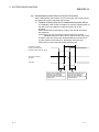
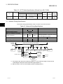
2.2.2 Notes on System Configuration
(1) Position of QJ61CL12
Be sure to place the QJ61CL12 on the end of the trunk line.
It may seem to be placed at any other point than both ends of the trunk line in
appearance because of application of the T-branch connection. Note that the
length of the trunk line is defined as the length between two terminating resistors.
Master station
Terminating resistor *3
Length of drop line*1
Length of trunk line
Length
*3
of
Terminating drop
line
resistor
*2
Power
supply
adapter
*1
Length of drop line
Remote
station
Remote
station
*2
*2
Remote
station
*2
*3
Remote
station
Remote
station
Remote
station
Remote
station
Distance
between stations
Remote
station
Remote
station
Trunk line
Drop line
Remote
station
*1: The length of the drop line includes the length of *2. (The maximum length of drop line and
overall length of drop lines also include the length marked *2.)
*3: Refer to Section 4.5.4 for the terminating resistor installing method.
2-5
2-5
2 SYSTEM CONFIGURATION
MELSEC-Q
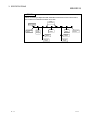
(2) Number of drop line stages
The drop line in the CC-Link/LT system may be branched in up to two stages.
It cannot be branched in three or more stages.
Remote
station
Remote
station
Third drop line branch stage: cannot be wired.
Trunk line
Drop line
Remote
station
(3) Conditions for setting of dedicated power supply or power supply
adapter
The conditions for the setting of a dedicated power supply or power supply
adapter for the CC-Link/LT vary depending on the devices to be connected and
the wiring length.
See the User’s Manual of the dedicated power supply or power supply adapter
for the conditions.
POINT
Always connect the dedicated power supply or power supply adapter to the trunk
line. (Connection to branch lines is not allowed.)
(4) Prevention of faulty input/output from remote I/O module
To prevent faulty input/output from remote I/O modules, pay attention to the
following when designing the system.
(a) When power is ON or OFF
Turn ON the remote I/O module (Turn on the dedicated power supply or
power supply adapter) before starting the data link.
Also, stop the data link before turning OFF the remote I/O module (Turning
off the dedicated power supply or power supply adapter).
Data link start
Master module
(Data link status)
Remote I/O module
(Power status)
2-6
Data link stop
Executed
Stopped
ON
OFF
2-6
2 SYSTEM CONFIGURATION
MELSEC-Q
(b) Instantaneous power failure of remote I/O module
When instantaneous power failure occurs in the power source (24V DC) for
the remote I/O module, faulty data may be input.
1) Causes of faulty input due to instantaneous power failure
The hardware of the remote I/O module converts the supplied power of
24V DC into 5V DC inside the module and uses it for its own
operation.
When instantaneous power failure occurs in the remote I/O module,
the expression,
(Time until 5V DC is turned OFF inside the remote I/O module)
>(Response time from ON to OFF of the input unit), are formed.
Therefore, when the devices are refreshed within the time shown as
(1), data will be erroneously input. (Especially, when the input
response time is set to the high-speed response type)
1)
Remote I/O module
(Power for module and
external supply power for input)
Remote I/O module
(5V DC)
Input (Xn)
Due to OFF of external supply
power for input detection,
input (Xn) turns OFF after
response time from ON to OFF
of Input unit.
2-7
Due to ON of external supply
power for input detection,
input (Xn) turns ON after
response time from OFF to ON
of input module.
2-7
2 SYSTEM CONFIGURATION
MELSEC-Q
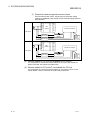
2) Preventive measure against erroneous input
CPU
module
DC input
Master module
To
Power supply
module
From the same power source, supply power to the power supply
module, the stabilized power supply and the external supply power for
input detection.
Remote I/O module
Power supply
adapter
Stabilized
power supply 24V DC
External
supply
power
for input
CPU
module
AC input
Stabilized
power supply 24V DC
Master module
To
Power supply
module
Stabilized
power supply 24V DC
Remote I/O module
Power supply
adapter
External
supply
power
for input
(5) Remote station for CC-Link not available for CC-Link/LT
It is not possible to connect the remote station for CC-Link to the QJ61CL12.
When connected, the system may malfunction.
(6) Remote station for CC-Link/LT not available for CC-Link
It is not possible to connect the remote station for CC-Link/LT to the CC-Link
master station. When connected, the system may malfunction.
2-8
2-8
2 SYSTEM CONFIGURATION
MELSEC-Q
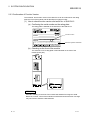
2.2.3 Confirmation of Function Version
The serial No. and function version of the QJ61CL12 can be confirmed on the rating
plate, the front of the module and GX Developer's system monitor.
(1) How to check function version and serial No. of QJ61CL12
(a) Confirming the serial number on the rating plate
The rating plate is situated on the side face of the QJ61CL12.
Function version
MODEL
SERIAL 100915000000000-B
Relevant regulation standards
MADE IN JAPAN
(b) Checking on the front of the module
The serial No. on the rating plate is also indicated on the front of the
module (lower part).
100915000000000-B
Serial No.
REMARK
Serial No. labelling on the front of the module was started from August in 2008.
Note that, however, some of the modules manufactured around the time of change
may not have the serial No. label attached.
2-9
2-9
2 SYSTEM CONFIGURATION
MELSEC-Q
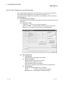
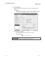
(c) Confirming the serial number on the system monitor (Product
Information List)
To display the screen for checking the serial number and function version,
select [Diagnostics]
[System Monitor] and click the Product Inf. List
button in GX Developer.
Function version
Serial No.
Production number
1) Production number display
Since the QJ61CL12 does not support the production number display,
"-" is displayed.
POINT
The serial No. displayed in the Product Information List of GX Developer may be
different from the one on the rating plate and the front of the module.
• The serial No. on the raging plate and the front of the module indicates the
management information on the product.
• The serial No. in the Product Information List of GX Developer indicates the
functional information on the product, which is updated when a new function is
added.
2 - 10
2 - 10
3 SPECIFICATIONS
MELSEC-Q
3 SPECIFICATIONS
This chapter describes about specifications of the QJ61CL12.
For the general specifications of the QJ61CL12, refer to the User’s Manual of the CPU
module to be used.
3.1 Performance Specifications
The performance specifications are given in Table 3.1.
Table 3.1 Performance Specifications
Item
Control spec.
Communication
spec.
Maximum link points
(When the same I/O address is used)
Link points per station
(When the same I/O address is used)
No. of points
When 32
2.5 Mbps
stations
625 kbps
connected
156 kbps
Link scan
time
No. of points
When 64
2.5 Mbps
stations
625 kbps
connected
156 kbps
Transmission speed
Communication method
Communication path
Error control system
Maximum number of modules
Remote station No.
Installation position of master station
RAS-oriented functions
Connection cable *1
I/O occupied points *2
5V DC Internal current consumption
Voltage
24V DC power supply *3
Current consumption
Current on startup
Weight
Specifications
4-point mode
8-point mode
16-point mode
256 points
512 points
1024 points
(512 points)
(1024 points)
(2048 points)
4 points
8 points
16 points
(8 points)
(16 points)
(32 points)
128 points
256 points
512 points
0.7 ms
0.8 ms
1.0 ms
2.2 ms
2.7 ms
3.8 ms
8.0 ms
10.0 ms
14.1 ms
256 points
512 points
1024 points
1.2 ms
1.5 ms
2.0 ms
4.3 ms
5.4 ms
7.4 ms
15.6 ms
20.0 ms
27.8 ms
2.5 Mbps/625 kbps/156 kbps
BITR (Broadcastpolling + Interval Timed Response)
T-branch type
CRC
64
1 to 64
End of trunk line
Network diagnosis, Internal loopback diagnosis,
Station detach function, Automatic return function
2
Dedicated flat cable (0.75mm X4) *5,
VCTF cable *4, high flexible cable *5
16, 32, 48, 64, 128, 256, 512, 1024
(I/O assignment: Intelli.)
0.13 A
20.4 to 28.8V DC
0.028 A
0.070 A
0.09 kg
*1: Performance of the CC-Link/LT cannot be guaranteed for use of cables other than the dedicated flat
cables, VCTF cables and high flexible cables.
*2: Set with the operation setting switch. (Refer to Section 4.3.).
*3: Supplied through the dedicated power supply or power supply adapter.
*4: For VCTF cable specifications, refer to Table 3.2.
*5: Use the dedicated flat cables and high flexible cables accredited by the CC-Link Partner Association.
(Refer to Section 4.2.3.)
3-1
3-1
3
3 SPECIFICATIONS
MELSEC-Q
Table 3.2 VCTF Cable Specifications (Extract from JIS C 3306)
Conductor
Type
No. of cores Nominal crosssectional area
Vinyl cabtyre,
2
4
Round cord
Composition
Outside
No. of wires/wire diameter diameter
0.75mm
30/0.18mm
Insulator
Sheath
thickness
thickness
0.6mm
1.0mm
1.1mm
Conductor
resistance
(20
)
25.1Ω
/km
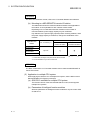
3.1.1 Network Wiring Specifications
3
The network wiring specifications of the CC-Link/LT are as shown below.
Table 3.3 Network Wiring Specifications
Item
Spec.
Transmission speed
2.5 Mbps
Distance between stations
Remarks
625 kbps
156 kbps
Not limited
Max. No. of stations on a drop line
Length of trunk line
8
35 m
T-branch interval
100 m
500 m
Cable length between 2 terminating resistors
(Drop line length not included)
Not limited
Max. length of drop line
4m
16 m
60 m
Cable length per branch line
Overall length of drop lines
15 m
50 m
200 m
Total length of all drop lines
T-branch
connection
Length of trunk line (Drop line not included)
Master station
Interval length of T-branch
Length
of
*3
drop
Terminating line
resistor
Power
supply
adapter
*1
Length of drop line
Remote
station
Remote
station
*2
Remote
station
Remote
station
*3
Remote Terminating
station resistor
Remote
station
Remote
station
Distance
between stations
Remote
station
Remote
station
Trunk line
Drop line
Remote
station
*1: The length of the drop line includes the length of *2. (The maximum length of drop line and
overall length of drop lines also include the length marked *2.)
*3: Refer to Section 4.5.4 for the terminating resistor installing method.
3-2
3-2
3 SPECIFICATIONS
MELSEC-Q
POINT
When connecting multiple lines with dedicated connectors to form one trunk line,
the number of connections must be 10 or less.
Line
connection
Master station
Terminating
resistor
Remote
station
Power
supply
adapter
Remote
station
Remote
station
3-3
Remote
station
Terminating
resistor
Remote
station
Remote
station
3-3
3 SPECIFICATIONS
MELSEC-Q
3.2 I/O Signals to/from Programmable Controller CPU
This section describes Input/Output (I/O) signals of the QJ61CL12 to/from the
programmable controller CPU.
Input signals (X) or output signals (Y) are allocated to the area of the Remote Input or
the Remote Output respectively. No I/O signals are required to activate the
QJ61CL12.
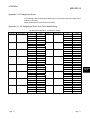
The assignment of I/O signals varies depending on the point mode setting.
In the following Table 3.3 to 3.5, "n" represents the start I/O number of the QJ61CL12.
[Example]
When the start I/O number of the QJ61CL12 is "X/Y30":
Xn0 to XnF X30 to X3F
Yn0 to YnF Y30 to Y3F
POINT
When the number of I/O points occupied is set exceeding the maximum number of
link points in the 4-point or 8-point mode, the excessive I/O points cannot be used.
Example) When setting as follows:
Point mode:4-point mode; No. of I/O point occupied:1024;
The QJ61CL12 occupies 1024 points of I/O for the programmable
controller CPU, however, available link points are 256 (Max. link points
for 4-point mode are 256) and the remaining points of 768 are not
possible to be used.
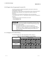
3.2.1 I/O Signals in 4-Point Mode Setting
List of the I/O signals in the 4-point mode setting is shown in Table 3.4.
Table 3.4 List of I/O Signals in 4-point Setting
Input No.
XnF to Xn0
Remote Input (X)
F
E
D
C
B
A
9
8
Station No.4
Station No.3
Station No.64
Station No.63
to
X (n F) F to X (n F) 0
Output No.
YnF to Yn0
3-4
6
5
4
3
2
1
0
Station No.2
Station No.1
Station No.62
Station No.61
to
Remote Output (Y)
F
E
D
C
B
A
9
8
Station No.4
Station No.3
Station No.64
Station No.63
to
Y (n F) F to Y (n F) 0
7
7
6
5
4
3
2
1
0
Station No.2
Station No.1
Station No.62
Station No.61
to
3-4
3 SPECIFICATIONS
MELSEC-Q
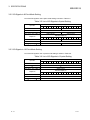
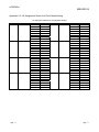
3.2.2 I/O Signals in 8-Point Mode Setting
List of the I/O signals in the 8-point mode setting is shown in Table 3.5.
Table 3.5 List of I/O Signals in 8-point Setting
Input No.
Remote Input (X)
F
E
XnF to Xn0
D
C
B
A
9
8
7
6
Station No.2
5
4
3
2
1
0
1
0
Station No.1
to
to
X (n 1F) F to X (n 1F) 0
Output No.
Station No.64
Station No.63
Remote Output (Y)
F
E
YnF to Yn0
D
C
B
A
9
8
7
6
Station No.2
5
4
3
2
Station No.1
to
to
Y (n 1F) F to Y (n 1F) 0
Station No.64
Station No.63
3.2.3 I/O Signals in 16-Point Mode Setting
List of the I/O signals in the 16-point mode setting is shown in Table 3.6.
Table 3.6 List of I/O Signals in 16-point Setting
Input No.
F
E
D
C
B
A
9
8
7
6
XnF to Xn0
Station No.1
to
to
X (n 3F) F to X (n 3F) 0
Station No.64
Output No.
3-5
Remote Input (X)
5
4
3
2
1
0
5
4
3
2
1
0
Remote Output (Y)
F
E
D
C
B
A
9
8
7
6
YnF to Yn0
Station No.1
to
to
Y (n 3F) F to Y (n 3F) 0
Station No.64
3-5
3 SPECIFICATIONS
MELSEC-Q
3.3 Buffer Memory
The buffer memory is used for data communication between the QJ61CL12 and the
CPU module and is read or written by GX Developer or sequence programs.
When the system is powered OFF or the CPU module is reset, the contents of the
buffer memory will return to the default setting.
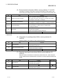
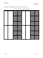
3.3.1 List of Buffer Memory
The list of the buffer memory is shown in Table 3.7.
Table 3.7 List of Buffer Memory
Address
Item
Availability
Reference
0H to 3H
Information of remote station connection
Read only
Sec.3.3.2 (1)
4H to 7H
Information of faulty station
Read only
Sec.3.3.2 (2)
Read only
Sec.3.3.2 (3)
DEC
HEX
0 to 3
4 to 7
8 to 11
8H to BH
Remote I/O error information
12 to 15
CH to FH
Prohibited*
16
10H
Detailed error information
Readable/Writable
Sec.3.3.2 (4)
17
11H
External switch information
Read only
Sec.3.3.2 (5)
18
12H
Information of operating states
Read only
Sec.3.3.2 (6)
19
13H
Data link stop/restart instructions
Writable
Sec.3.3.2 (7)
Read only
Sec.3.3.2 (8)
Read only
Sec.3.3.2 (9)
20
14H
Information of last station of data link
21 to 31
15H to 1FH
Prohibited*
32
20H
Detailed remote station information (Station No. 1)
to
to
to
95
5FH
Detailed remote station information (Station No.64)
96 to
60H to
Prohibited*
* Do not write to the prohibited area. Doing so may cause an error.
3.3.2 Details of Buffer Memory
This section describes the details of each item given in Table 3.7 in Section 3.3.1.
(1) Information of remote station connection (Buffer memory address 0
- 3: Un\G0 – 3)
The remote stations connected to the line are detected and the information on
the connection condition is stored in this area.
Address (Decimal)
b15
b14
b13
to
b2
b1
b0
0
Station No.16
Station No.15
Station No.14
to
Station No.3
Station No.2
Station No.1
1
Station No.32
Station No.31
Station No.30
to
Station No.19 Station No.18 Station No.17
2
Station No.48
Station No.47
Station No.46
to
Station No.35 Station No.34 Station No.33
3
Station No.64
Station No.63
Station No.62
to
Station No.51 Station No.50 Station No.49
0: No remote station connected
1: Remote station connected
3-6
3-6
3 SPECIFICATIONS
MELSEC-Q
(2) Information of faulty station (Buffer memory address 4 - 7: Un\G4 – 7)
The data link states of remote stations are stored in this area.
Address (Decimal)
b15
b14
b13
to
b2
b1
b0
4
Station No.16
Station No.15
Station No.14
to
Station No.3
Station No.2
Station No.1
5
Station No.32
Station No.31
Station No.30
to
Station No.19 Station No.18 Station No.17
6
Station No.48
Station No.47
Station No.46
to
Station No.35 Station No.34 Station No.33
7
Station No.64
Station No.63
Station No.62
to
Station No.51 Station No.50 Station No.49
0: Normal
1: Data link error
(3) Remote I/O error information (Buffer memory address 8 - 11:
Un\G8 – 11)
Information on remote I/O error of each remote station executing data link is
stored in this area.
For individual errors, see the related manual for the remote station.
Address (Decimal)
b15
b14
b13
to
b2
b1
b0
8
Station No.16
Station No.15
Station No.14
to
Station No.3
Station No.2
Station No.1
9
Station No.32
Station No.31
Station No.30
to
Station No.19 Station No.18 Station No.17
10
Station No.48
Station No.47
Station No.46
to
Station No.35 Station No.34 Station No.33
11
Station No.64
Station No.63
Station No.62
to
Station No.51 Station No.50 Station No.49
0: No remote I/O Error identified
1: Remote I/O error identified
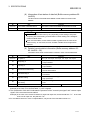
(4) Detailed error information (Buffer memory address 16: Un\G16)
Detailed information on errors detected by the master station is stored in this
area. When an error is detected in a station outside the control range, b3 will be
latched. Writing “1” to this area (b3) clears the error information of the station.
Bit
Item
b0
Data link failure
b1
All stations failed
b2
Remote I/O error
Contents
0: Data link normal
1: One or more faulty station in data link identified
0: One or more normal data link station identified
1: All stations are faulty
0: No remote I/O error
1: One or more faulty remote I/O station
0: No error
b3
Error of station outside control range
1: Remote station(s) set to the station number higher than the last
of refresh range
b4
Point mode setting error
b5
Transmission speed setting error
b6
Switching during operation
b14 to b7
b15
3-7
0: Normal
1: Point mode switch set outside valid range
0: Normal
1: Transmission speed setting switch set outside valid range
0: No switching
1: Switching identified
Vacant
Hardware failure
0: Normal
1: Failure identified by self-loopback test
3-7
3 SPECIFICATIONS
MELSEC-Q
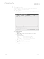
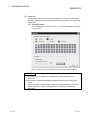
(5) External switch information (Buffer memory address 17: Un\G17)
Information of setting of I/O points occupied, transmission speed setting, point
mode setting and setting status of each switch in test mode is stored in this area.
Bit
Item
Contents
Status of operation setting switch SW3 – SW1
b2 to b0
Setting of I/O points occupied
000: 16 pts. 001: 32 pts. 010: 48 pts. 011: 64 pts. 100: 128 pts.
101: 256 pts. 110: 512 pts. 111:1024 pts
b4, b3
Transmission speed setting
b6, b5
Point mode setting
Status of operation setting switch SW5, SW4
00: 156 kbps 01: 625 kbps 10: 2.5 Mbps 11: Setting not allowed
Status of operation setting switch SW7, SW6
00: 8-point mode 01: 4-point mode 10: 16-point mode
11: Setting not allowed
Status of operation setting switch SW8
b7
Test mode
0: Under usual conditions
1: When self-loopback test being executed
b15 to b8
Vacant
0: Switch OFF
1: Switch ON
(6) Information of operating states (Buffer memory address 18:
Un\G18)
Operating states of the QJ61CL12 are stored in this area.
Bit
Item
0: Data link stopped
b0
Data link states
b1
Initial communication states
b15 to b2
Contents
1: Data link being executed
0: Initial communication not complete
1: Initial communication completed
Vacant
(7) Data link stop/restart instructions (Buffer memory address 19:
Un\G19)
Stop and restart of data link are controlled by data of this area. When stop and
restart of data link are requested at the same time, the stop request precedes the
restart.
Bit
b0
b14 to b1
b15
3-8
Item
Data link stop
Contents
0: Data link stop not requested
1: Data link stop requested
Initial value
0
Vacant
Data link restart
0: Data link restart not requested
1: Data link restart requested
0
3-8
3 SPECIFICATIONS
MELSEC-Q
(8) Information of last station of data link (Buffer memory address 20:
Un\G20)
The last number of the data-link-available remote stations is stored in this
address.
Bit
Item
b6 to b0
Last number of data link stations
b15 to b7
Vacant
Contents
Last number of data-link-available remote stations is stored
POINT
The values of this buffer memory vary depending on the setting of I/O points
occupied, point mode setting, and last station number setting of the intelligent
function module switch.
When a remote station, which station number is greater than the value of the
buffer memory, is connected, an error of station outside control range will be
detected.
(9) Detailed remote station information (Buffer memory address 32 95: Un\G32 – 95)
Information about each remote station is stored in each of these addresses.
Bit
b2 to b0
Item
Contents
I/O points *1
000: 1 pts. 001: 2 pts. 010: 4 pts. 011: 8 pts. 100: 16 pts.
b3
Output flag *2
0: No output
1: Output identified
b4
Input flag *2
0: No input
1: Input identified
b5
Remote device station flag
b6
First station flag *3
b7
Input filter setting
b8
b15 to b9
0: Remote I/O station
1: Remote device station
0: Not first station
1: First station
0: Standard input (No setting)
1: High-speed input
Clear of output/
0: Clear (No setting)
Hold setting
1: Hold
Vacant
*1 For I/O modules, the input or output points are stored.
Example) In the case of CL1XY2-DT1D5S, "1 point" is applied.
*2 The combination of b4 and b3 indicates the presence of the "remote input signal" and "remote output
signal" of the connected remote station.
Example) In the case of the remote I/O station for input and output use, b4 and b3 will form "11". In the case
of the one for input use, they will form "10".
*3 For a module that has 2 or more occupied stations, only the bit of the first station will turn on.
3-9
3-9
3 SPECIFICATIONS
MELSEC-Q
3.4 Concept of Control Point (Point Mode Setting and I/O Point Setting)
This section describes concept of the point mode setting and I/O point setting, which is
required for system configuration.
By the point mode setting, the number of points that the system can control is set to
each remote station.
There are 3 kinds of point modes: 4-point, 8-point and 16-point modes. Even in the
same number setting of the I/O points occupied, the number of controllable remote
stations will vary depending on the point mode setting.
Note that, when connecting a remote device station to the system, use the 16-point
mode.
3.4.1 Simplified Setting
This section describes simple setting by which a point mode and I/O points occupied
can be set.
According to the I/O points of the remote station, set the proper points and the mode
shown in the following Table.
Remote station I/O points
256 or less
257 to 512 points
513 to 1024 points
Setting of I/O points occupied for
QJ61CL12
16 points
32 points
64 points
128 points
256 points
512 points
1024 points
Point mode setting for
QJ61CL12
4-point mode
8-point mode
16-point mode
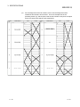
3.4.2 Advanced Setting
This section describes the advanced setting method of the point mode and the I/O
points occupied.
(1) Even if the same I/O points occupied is set, the number of controllable remote
stations varies depending on which point mode is selected.
The table below shows the relation among the I/O point setting, point mode
setting and number of stations that can be connected
I/O occupied point setting
Point 4-point mode
mode 8-point mode
setting 16-point mode
16 pts.
32 pts.
48 pts.
64 pts.
128 pts.
256 pts.
512 pts.
1024 pts.
4 stations 8 stations 12 stations 16 stations 32 stations 64 stations 64 stations 64 stations
2 stations 4 stations 6 stations 8 stations 16 stations 32 stations 64 stations 64 stations
1 stations 2 stations 3 stations 4 stations 8 stations 16 stations 32 stations 64 stations
POINT
When the number of I/O points occupied is set exceeding the maximum number of
link points in the 4-point or 8-point mode, the excessive I/O points cannot be used.
Example) When setting as follows:
Point mode:4-point mode; No. of I/O point occupied:1024;
The QJ61CL12 occupies 1024 points of I/O for the programmable controller
CPU, however, available link points are 256 (Max. link points for 4-point
mode are 256) and the remaining points of 768 are not possible to be used.
3 - 10
3 - 10
3 SPECIFICATIONS
MELSEC-Q
(2)
The number of occupied stations for a remote module varies depending on the
point mode.
For a 16-point module, the setting in the 4-point, 8-point or 16-point mode makes
it occupy 4, 2 or 1 station(s) respectively.
(3)
The desirable selection of the point mode is dependent on the points of the
remote module to be used. Generally, setting the point mode in accordance to
the points of the module that are used the most in the system can reduce useless
points.
A setting example is as follows.
Example) In the system including: 2-point remote station:1, 4-point remote
station: 4, 8-point remote station:1, 16-point remote station:1
Master station
Station (1)
Station (2)
4 input points 8 input points
Station (3)
4 output points
Station (5)
16 input points
CL1X4-D1B2 CL2X8-D1B2
CL1Y4-T1B2
CL2X16-D1M1V
Station (4)
2 output points
Station (6)
4 I/O points
CL1Y2-T1D2S
Station (7)
4 output points
CL1XY8-DT1B2
CL1Y4-R1B2
4-point mode (4 pts./station) 8-point mode (8 pts./station) 16-point mode (16 pts./station)
I/O occupied points: 128
I/O occupied points: 48
I/O occupied points: 64
Total no. of stations : 7
Total no. of stations : 12
Total no. of stations : 8
X/Y0
X/Y10
(1) 4 pts.
1 station
(2) 8 pts.
2 stations
(3) 4 pts.
1 station
(4) 2 pts.
Vacancy for 2 pts.
1 station
X/Y0
(1) 4 pts.
Vacancy for 4 pts.
(2) 8 pts.
(3) 4 pts.
(5) 16 pts.
4 stations
X/Y20
X/Y23
(6) 4 pts.
1 station
(7) 4 pts.
1 station
Vacancy for
4 pts.
1 station
(4) 2 pts.
Vacancy for
6 pts.
(5) 16 pts.
Vacancy for 4 pts.
(7) 4 pts.
Vacancy for
4 pts.
(1) 4 pts.
Vacancy for
12 pts.
1 station
X/Y10
1 station
(2) 8 pts.
1 station
Vacancy for
8 pts.
1 station
X/Y20
2 stations
X/Y30
(6) 4 pts.
X/Y0
1 station
X/Y10
Vacancy for 4 pts.
X/Y20
1 station
(3) 4 pts.
Vacancy for
12 pts.
X/Y30
1 station
(4) 2 pts.
1 station
1 station
Vacancy for
14 pts.
1 station
(5) 16 pts.
1 station
X/Y40
X/Y50
(6) 4 pts.
Vacancy for
12 pts.
X/Y60
1 station
(7) 4 pts.
Vacancy for
12 pts.
1 station
X/Y70
Vacancy for
16 pts.
3 - 11
3 - 11
3 SPECIFICATIONS
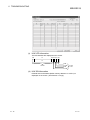
(4)
Station
No.
Model Name
MELSEC-Q
For the assignment of the I/O numbers, how to use the assignment sheet
included in this manual is shown below. This is an example case of the
preceding section (3), and the point mode and the number of I/O points occupied
are set to 8-point mode and 64 points respectively.
Input
Output
Station
No.
Model Name
Input
Output
(2 stations occupied)
3 - 12
3 - 12
3 SPECIFICATIONS
MELSEC-Q
3.5 Concept of Last Station Number Setting
The last station number is set to ensure the data link to be executed to the last remote
station and not to link to unconnected stations.
This setting is not essential, however, it is desirable to optimize the link scan time of
the system.
For the setting, see Section 4.4.
Example) By setting to 16-point mode and I/O occupied points of 128, and by setting
“5” to the last station number if the number of the connected remote stations
is 5, the link scan time is optimized.
Not connected
Remote
station
No.1
Remote
station
No.2
Remote
station
No.3
Remote
station
No.4
Remote
station
No.5
Remote
station
No.6
Remote
station
No.8
Remote
station
No.7
Data link range when last station is set to "5"
Data link range when last station number is NOT set
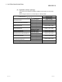
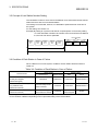
3.6 Condition of Each Station in Case of Failure
When a failure occurs in the system, conditions of each station will be as shown in
Table 3.8.
Table 3.8 Condition of Each Station in Case of Failure
Data link status
Master station
Remote station
Remote input
Remote output
Input
Output
Maintained
Maintained
Continued *1
Maintained/OFF *2
Continued
Continued *1
Maintained/OFF *2
When CPU module of master station
is faulty and stopped
(Data link stopped)
When remote station is faulty
(e.g. Data link error)
(Data link continued)
Input from faulty remote
station is cleared
When remote station is de-energized
Input from de-energized
(Data link continued)
remote station is cleared
Continued
Depends on
external signals
All OFF
*1 Although external data will be input (Input LED indicator lit), data cannot be sent to the master station.
*2 The condition is different depending on the output hold setting of the remote station.
3 - 13
3 - 13
3 SPECIFICATIONS
MELSEC-Q
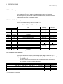
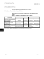
3.7 Data Link Processing Time
This section describes about the link scan time and transmission delay time.
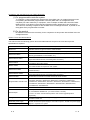
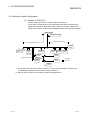
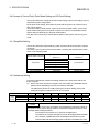
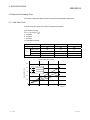
3.7.1 Link Scan Time
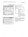
The link scan time of the CC-Link/LT is explained as follows:
[Link scan time (LS)]
LS = a + (b x N) x c [ s]
a: Constant
b: Constant
c: Constant
N: Last station number
Transmission speed
2.5 Mbps
625 kbps
156 kbps
a
22
88
353
4-point mode
46
41
37
8-point mode
56
51
47
16-point mode
76
71
67
0.4
1.6
6.4
b
c
Link scan time (At 2.5 Mbps)
2.5
Link scan time (ms)
2.0
16-point mode
8-point mode
4-point mode
1.5
1.0
0.5
0
0
3 - 14
20
40
60
Number of
stations
3 - 14
3 SPECIFICATIONS
MELSEC-Q
3.7.2 Transmission Delay Time
The Transmission delay time (Time taken for data to reach the destination) is
explained in this section.
(1) Master Station
Remote Station (Input)
Time from the point that signals are input to a remote station to the point that the
device (X) of the programmable controller CPU turns ON/OFF, is obtained from
the formula as shown below.
[Formula]
SM x 2 + (2 – n)*1 x LS + Input response time of remote station (ms)
SM: Sequence program scan time of master station
LS: Link scan time (See Section 3.7.1)
n: Values of (SM/LS) after omitting figures below decimal point
*1: 0 if the value is 0 or less.
(Example) When the master station’s sequence scan time is 5 ms, the link scan
time is 1.2 ms, and the input response time of remote I/O station is 1.5
ms:
SM x 2 + (2 – n)*1 x LS + Input response time of remote station (ms)
= 5 x 2+ (2 – 4)*1 x 1.2 + 1.5 [n = 4 (5/1.2 = 4.16 , Omitting figures
below decimal point)]
= 11.5 [ms]
(2) Master Station
Remote Station (Output)
Time from the point that the programmable controller CPU’s device (Y) turns
ON(OFF) to the point that the remote station’s output turns ON (OFF) is obtained
from the formula shown below.
[Formula]
SM + LS x 2 + Output response time of remote station (ms)
SM: Sequence program scan time of master station
LS: Link scan time (See Section 3.7.1)
(Example) When the master station’s sequence scan time is 5 ms, the link scan
time is 1.2 ms, and the output response time of remote I/O station is
0.5 ms:
SM + LS x 2 + output response time of remote I/O station (ms)
= 5 + 1.2 x 2+ 0.5
= 7.9 [ms]
3 - 15
3 - 15
3 SPECIFICATIONS
MELSEC-Q
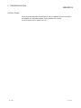
MEMO
3 - 16
3 - 16
4 PREPARATORY PROCEDURES FOR DATA LINK
MELSEC-Q
4 PREPARATORY PROCEDURES FOR DATA LINK
Procedures from the installation of the module to the start of data link are given in this
section.
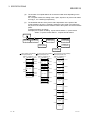
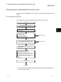
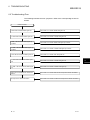
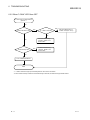
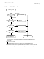
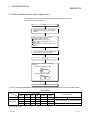
4.1 Procedures for Data Link
The following steps should be performed for data link of the CC-Link/LT.
Start
Mount QJ61CL12 on base unit.
Install remote module(s) into control box
or machines.
Set switches of QJ61CL12
Point mode setting
I/O occupied point setting
Transmission speed setting
Connect modules with dedicated flat cables,
VCTF cables and/or high flexible cables.
Set terminating resistor at end of trunk line.
4
Refer to Section 4.3
Refer to Section 4.5
Connect dedicated power supply or power
supply adapter.
Before powering ON, check that:
Modules are correctly installed
Voltage for power supply adapter is 24V DC.
CPU`s RUN/STOP switch is set to "STOP".
*1
CPU`s RESET switch is set in "central position".
No station number of remote stations is
duplicated.
Power ON
To next page
*1: Only for the Q02/Q02H/Q06H/Q12H/Q25H/Q02PH/Q06PH/Q12PH/Q25PHCPU
and C Controller module.
4-1
4-1
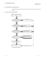
4 PREPARATORY PROCEDURES FOR DATA LINK
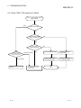
MELSEC-Q
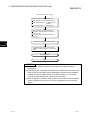
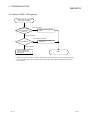
Continued from previous page
Check operation with LEDs (QJ61CL12)
When data link is normal :L RUN lights up.
When data link is faulty :L. ERR. lights up
or blinks.
:ERR. lights up.
When setting is faulty
Check connection of each module with:
Information of remote station`s connection
(Sec. 3.3.2 (1))
CC-Link/LT diagnosis (Operation check)
(Sec. 6.6)
Write control programs to CPU module.
4
Turn RESET switch of CPU module from
"RESET" to "central position", or power OFF
to ON
System Operation
END
POINT
(1) If some station number is duplicated, the station may malfunction (faulty
input/output).
(2) Depending on the combination of the point mode setting and the number of I/O
points for the remote station used, multiple station numbers may be assigned.
Carefully check if the station number of the remote station of 8 or more I/O
points is not duplicated with the number of the next station.
(3) When changing the operation setting switches of the master or remote stations
while the system is ON, be sure to turn OFF and ON the power of the entire
system.
4-2
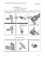
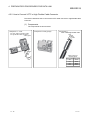
4-2
4 PREPARATORY PROCEDURES FOR DATA LINK
MELSEC-Q
4.2 Installation
This section describes handling precautions on the steps from the unpacking to the
installation of the QJ61CL12.
For more details on the module installation, refer to the User’s Manual of your CPU
module.
4.2.1 Handling Precautions
(1)
The module is mode of resin. Do not drop or give it a strong impact.
(2)
Do not remove the PCB (printed-circuit board) from the case. Doing so may
cause failure.
(3)
When wiring, be careful not to let foreign matter such as wiring chips enter the
module inside. Remove it if this happens.
(4)
The module has an ingress prevention label on its top to prevent foreign matter,
such as wire offcuts, from entering the module during wiring.
Do not peel this label during wiring.
Before starting system operation, be sure to peel this label because of heat
dissipation.
(5)
Tighten the module fixing screws within the torque range shown below.
Screws
Module fixing screws (M3 screws)*1
Tightening torque range
0.36 to 0.48 N.m
*1: The module can be easily fixed onto the base unit using the hook at the top of the
module.
However, it is recommended to secure the module with the module fixing screw if
the module is subject to significant vibration.
POINT
When removing the terminating resistor due to any system modification, be sure to
power OFF the system.
Removing/Installing the terminating resistor with the power ON may cause
malfunctions (faulty input/output).
4.2.2 Installation Environment
For the environment appropriate for installation, refer to the User’s Manual of your CPU
module.
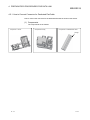
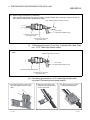
4.2.3 Cables, Connectors and Terminating Resistors
For inquiries about the cables, connectors and/or terminating resistors, refer to the
following:
http://www.cc-link.org/
4-3
4-3
4 PREPARATORY PROCEDURES FOR DATA LINK
MELSEC-Q
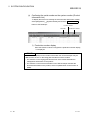
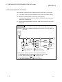
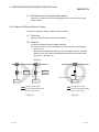
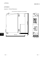
4.3 Name of Parts and Setting
This section describes the names of the parts, LED indications and setting methods of
the switches.
1)
2)
3)
4)
4-4
4-4
4 PREPARATORY PROCEDURES FOR DATA LINK
No.
1)
Item
MELSEC-Q
Contents
LED indicator
Module condition is checked with LED status.
LED
QJ61CL12
RUN
SD
ERR.
2)
L RUN
RD
L ERR.
Operation setting switch
Description
RUN
ON: Module operating normally
OFF: Fault in hardware
ERR.
ON: Faulty switch setting
Blink: Switched during operation
L RUN
<Usually>
ON: Data link being executed
OFF: Data link stopped
<In test mode>
ON: Self-loopback test resulted in normal
OFF: Self-loopback test failure
L ERR.
<Usually>
ON: Faulty data link station or station outside control range detected
Blink: Data link failure at all stations
<In test mode>
ON: Self-loopback test failure
OFF: Self-loopback test resulted in normal
SD
ON:
Data being transmitted
RD
ON:
Data being received
Setting I/O points occupied, transmission speed, etc of QJ61CL12 (Factory
setting: OFF)
I/O points
occupied
1
Operation setting switches
2
I/O
POINTS
3
Transmission
speed setting
4
5
B RATE
Point mode
setting
6
7
MODE
16 pts.
32 pts.
48 pts.
OFF
64 pts. 128 pts. 256 pts. 512 pts. 1024 pts.
ON
OFF
ON
OFF
ON
OFF
OFF
ON
ON
OFF
OFF
OFF
OFF
OFF
OFF
ON
ON
OFF
ON
ON
ON
ON
ON
625kbps
2.5Mbps
Setting prohibited*
OFF
ON
OFF
ON
OFF
OFF
ON
ON
8-point mode
4-point mode
16-point mode
Setting prohibited*
OFF
ON
OFF
ON
OFF
OFF
ON
ON
156kbps
Test mode
8
TEST
OFF: ON LINE (Normal operation)
ON : Test mode (Self-loopback test)
* When the switch is set to this, ERR. LED will light up
3)
CC-Link/LT Interface
connector
Connector for CC-Link/LT communication line connection
4)
Serial number plate
Indicates the serial No. of the QJ61CL12.
POINT
The settings of operation setting switches become valid when the module is turned
ON from OFF or when the CPU module is reset. When any of settings are
changed with the module powered ON, “ERR.” LED will blink. In this case, turn
OFF and restart the system.
4-5
4-5
4 PREPARATORY PROCEDURES FOR DATA LINK
MELSEC-Q
4.4 Switch Setting of Intelligent Function Module
The switch setting of the intelligent function module is performed in "I/O assignment
settings" of GX Developer.
(1) Setting Item
Switches 1 through 5 are provided for the intelligent function module and 16-bit
data are used for the settings. When the intelligent function module switch
setting is not set, the default for Switch 1 is 0.
Setting item
Set the last number of the stations that execute data link.
This setting disables data link processing for non-connected
stations, reducing link refresh time. (See Sec.3.5) When the
last number exceeds the number of connectable stations
Last station
(see Sec.3.4.2), the setting is ignored.
Switch 1
number setting
<Setting range>
1 to 64
When 0 or greater than 65 is set, data link will be executed within
the range of connectable station numbers.
Switch 2
No setting (blank)
Switch 3
No setting (blank)
Switch 4
No setting (blank)
Switch 5
No setting (blank)
POINT
Do not set Switch 2 through 5. If any setting is made, normal operation may be
affected.
4-6
4-6
4 PREPARATORY PROCEDURES FOR DATA LINK
MELSEC-Q
(2) Operating procedures
Start settings on the I/O assignment setting screen of GX developer.
(a) I/O assignment setting screen
Set the following to the slot where QJ61CL12 is
installed.
The “Type” setting is indispensable; set other
items as needed.
Type
:Select "Intelli".
Model
:Enter the model name of the
module.
Points
:Select the number of the I/O points
occupied.
Start XY
:Enter the start I/O number of
QJ61CL12.
Detailed setting :Specify the control CPU of
QJ61CL12. Because "Error time
output mode" or "H/W error time
PLC operation mode" are invalid
for QJ61CL12, these settings are
not required
(b) Intelligent function module switch settings screen
Click on [Switch setting] on the "I/O assignment
settings" screen to display the screen shown left
and make setting for Switch 1.
The setting can easily be made if the value is
entered in decimal. Change the entry format to
decimal notation.
4-7
4-7
4 PREPARATORY PROCEDURES FOR DATA LINK
MELSEC-Q
4.5 Connecting Modules with Cables
The connection method using the cables designed for CC-Link/LT is as follows:
(1)
The cables can be connected regardless of the order of the station number.
(2)
Be sure to set the QJ61CL12 at the end of the trunk line.
The terminating resistor close to the QJ61CL12 should be connected within
20cm from the QJ61CL12.
(3)
Connect terminating resistors to the both ends of the trunk line of CC-Link/LT
without fail.
POINT
Calculate the number of required connectors referring to the following example.
Example) When using a dedicated flat cable as a trunk line and VCTF cables as
drop lines
QJ61
CL12
1)-1
4)-1
1)-2
1)-3
1)-6
1)-4
1)-7
2)-1
1)-8
1)-9
3)-1
1)-5
Power supply
adapter
1)-10
2)-2
Remote
module
Remote
module
1)-11
2)-3
1)-12
2)-4
2)-5
3)-2
General
power supply
(24V DC)
1)-17
2)-6
Remote
module
2)-7
1)-13 1)-14 1)-15
2)-8
1)-18
Remote
module
20cm or less
Remote
module
Remote
module
1)-19 4)-2
1)-16
Trunk line (Dedicated flat cable)
VCTF cable connector
Drop line (Dedicated flat cable)
Dedicated flat cable connector
Drop line (VCTF cable)
Terminating resistor (CL9-TERM)
Remote
module
Remote
module
Module
with cable
Commercially
available terminal
The number of required connectors can be obtained as follows:
1) Dedicated flat cable connectors (No. of ): 19 ( 1)-1 to 1)-19)
2) VCTF cable connectors (No. of ): 8 ( 2)-1 to 2)-8)
3) Terminal blocks (No. of
): 2 ( 3)-1 to 3)-2)
4) Terminating resistors (No. of ): 2 ( 4)-1 to 4)-2)
4-8
4-8
4 PREPARATORY PROCEDURES FOR DATA LINK
MELSEC-Q
4.5.1 How to Connect Connector for Dedicated Flat Cable
How to connect the connector for the dedicated flat cable is shown in this section.
(1) Components
The components are as follows:
Component 1: Cover
Component 2: Body
Component 3: Dedicated flat cable
Orange
4-9
4-9
4 PREPARATORY PROCEDURES FOR DATA LINK
MELSEC-Q
(1) Operating steps
The operating steps are illustrated below.
(a) Processing Cable End
1) Properly place the dedicated flat cable
in the cover. (Check that the position
of the orange part is correct.)
2) Close the cover so that the flat cable
will be held between both sides of the
cover.
3) Assemble the cover with the body and
press-fit them with pliers.
Orange
Orange
Orange
Note 1) This setting position is wrong.
Orange
Note 2) If the orange part is seen through
the guide hole in the front cover,
the wiring is not correct. Open
the cover and perform the
previous step again.
4) Check that all of four latches are
engaged. Press-fitting is completed.
Orange
Orange
(b) T-Branch Processing
5) Cut 2 portions of the edge of the cover
with nippers and remove the edge.
6) Set the cover at the point where
T-branch is to be set.
7) Follow the instructions of steps 3 and
4 shown above to execute press-fitting.
Orange
Cut
4 - 10
Orange
4 - 10
4 PREPARATORY PROCEDURES FOR DATA LINK
MELSEC-Q
4.5.2 How to Connect VCTF or High Flexible Cable Connector
This section describes how to connect the VCTF cable connector or high flexible cable
connector.
(1) Components
The components are shown below.
Component 1: Cover
Component 2: Body (Aqua)
For VCTF cable connection: Green
For high flexible cable connection:
Yellow green
n
Gree
k
c
Bla
e
Whit
Red
r
Cove
e
id
s
in
4 - 11
Component 3:
VCTF cable/High flexible cable
Red
White
Black
Green
Cable colors and
relevant signals
Signal name Cable color
+24V
Red
DA
White
DB
Black
24G
Green
4 - 11
4 PREPARATORY PROCEDURES FOR DATA LINK
MELSEC-Q
(1) Operating steps
The operating steps are shown below.
(a) Processing Cable End
1) Place each wire of the VCTF cable
or high flexible cable so that its wire
color matches the color inside the
cover.
2) Close the cover so that the wires
are properly fitted. When the
wiring is correct, the green cable
can be viewed through the hole.
If a red, white or black cable is
viewed through the hole, open
the cover and correct the wiring.
Incorrect wiring may cause failure
of the module.
3) Assemble the cover with the body
and press-fit them with pliers.
Red hite
W lack
B Green
4) Verify that 4 latches are engaged.
Press-fitting is complete.
4cm
Green: Correct wiring
Red, white or black: Incorrect wiring
(b) T-Branch Processing (VCTF cable/High flexible cable)
5)-1 When using a terminal block for T-branching
When connecting VCTF cables or high flexible cables to the terminal block, cable colors must be
matched for each terminal.
VCTF cable/
High flexible cable
VCTF cable/
High flexible cable
24G DB DA +24V
Red
White
Black
Green
VCTF cable/
High flexible cable
Note) When connecting a dedicated flat cable to the terminal block
(e.g. in a case where a VCTF cable is used for the trunk line
and dedicated flat cables for drop lines), each of "+24V",
"DA", "DB" and "24G" printed on the dedicated flat cable
must match the color of the VCTF or high flexible cable as
shown in the right table.
Split the dedicated flat cable into discrete "+24V", "DA", "DB"
and "24G" cables.
4 - 12
Dedicated flat
cable
VCTF cable/High
flexible cable
+24V
Red
DA
White
DB
Black
24G
Green
4 - 12
4 PREPARATORY PROCEDURES FOR DATA LINK
MELSEC-Q
5)-2 When using a connector for T-branching
After removing the sheath 7cm or more, make a T-branch wiring with a connector in the same way as
the T-branch method for the dedicated flat cable.
VCTF cable/High flexible cable (Trunk line)
VCTF cable/
High flexible cable(Drop line)
Connector for VCTF cable/
High flexible cable
Connector for VCTF cable/
High flexible cable
(c) T-Branching procedure (Trunk line: Dedicated flat cable, Drop
line: VCTF cable/High flexible cable)
6) Make a T-branch wiring with the connector in the same way as the T-branch method for the dedicated flat
cable.
Dedicated flat cable (Trunk line)
VCTF cable/
High flexible cable(Drop line)
Connector for dedicated flat cable
Connector for VCTF cable/
High flexible cable
(d) Processing procedure for VCTF cable/High flexible cable
connector (Connecting terminating resistor)
7) Cut off the 2 portions of the covers
edge with nippers and remove the
edge.
8) Place the cover at the point
where the terminating resistor
is to be connected.
9) Follow the step (a) 3) and 4)
and execute press-fitting.
Cut
4 - 13
4 - 13
4 PREPARATORY PROCEDURES FOR DATA LINK
MELSEC-Q
(3) Precautions for use of high flexible cables
Prevent an excessive load from being applied to the connector when moving
flexible cables.
4.5.3 Mixture of Different Kinds of Cables
This section describes mixture of different kinds of cables.
(1) Trunk line
Mixture of different kinds of cables is not allowed.
(2) Drop line
(a) Mixture of different kinds of cables is allowed.
(b) Using more than one kind of cables for the same drop line is not allowed.
(See Fig. 4.1.)
When using a module with cable (e.g. CL1Y2-T1D2S), however, dissimilar
cables can be connected if the dedicated flat cable of the module is 20cm
long or less. (See Fig. 4.2.)
[Example]
Remote
module
Remote
module
20cm or less
Module with cable
Remote
module
Remote
module
Trunk line (VCTF cable)
Trunk line (VCTF cable)
Drop line (Dedicated flat cable)
Drop line (Dedicated flat cable)
Drop line (VCTF cable)
Drop line (VCTF cable)
Fig. 4.1
4 - 14
Remote
module
Fig. 4.2
4 - 14
4 PREPARATORY PROCEDURES FOR DATA LINK
MELSEC-Q
(3) System configuration example for using dedicated flat cable as
trunk line
QJ61
CL12
Remote
module
Remote
module
Power supply
adapter
Remote
module
Module
with cable
Remote
module
Remote
module
General
power supply
(24V DC)
Remote
module
20cm or less
Remote
module
Remote
module
Trunk line (Dedicated flat cable)
VCTF/high flexible cable connector
Drop line (Dedicated flat cable)
Dedicated flat cable connector
Drop line (VCTF cable/High flexible cable)
Terminating resistor (CL9-TERM)
Commercially
available terminal
(4) System configuration example for using VCTF cable as trunk line
Connecting terminating resistor on QJ61CL12 side
Terminating resistor (CL9-TERM)
Install
QJ61
CL12
VCTF cable
connector
(For QJ61CL12)
VCTF cable
connector*
VCTF cable
(For terminating resistor)
* For the processing procedure for the VCTF cable connector
(for the terminating resistor), refer to Section 4.5.2.
Remote
module
Remote
module
Power supply
adapter
Remote
module
General
power supply
(24V DC)
4 - 15
Remote
module
Module
with cable
Remote
module
Remote
module
Remote
module
Trunk line (VCTF cable)
VCTF/high flexible cable connector
Drop line (Dedicated flat cable)
Dedicated flat cable connector
Drop line (VCTF cable/High flexible cable)
Terminating resistor (CL9-TERM)
20cm or less
Remote
module
Commercially
available terminal
4 - 15
4 PREPARATORY PROCEDURES FOR DATA LINK
MELSEC-Q
(5) System configuration example for using high flexible cable as trunk
line
Connecting terminating resistor on QJ61CL12 side
Terminating resistor (CL9-TERM)
Install
QJ61
CL12
High flexible
cable connector
(For QJ61CL12)
High flexible
cable connector*
(For terminating resistor)
High flexible
cable
* For processing procedure for the high flexible cable connector*
(for terminating resistor), refer to Section 4.5.2.
Remote
module
Remote
module
Power supply
adapter
Remote
module
General
power supply
(24V DC)
4 - 16
Remote
module
Module
with cable
Remote
module
Remote
module
Remote
module
Trunk line (High flexible cable)
VCTF/high flexible cable connector
Drop line (Dedicated flat cable)
Dedicated flat cable connector
Drop line (VCTF cable/High flexible cable)
Terminating resistor (CL9-TERM)
20cm or less
Remote
module
Commercially
available terminal
4 - 16
4 PREPARATORY PROCEDURES FOR DATA LINK
MELSEC-Q
4.5.4 Installing Terminating Resistors
Use the CL9-TERM (Gray) for the terminating resistor.
For the system configuration using the dedicated flat cables only, the CL9-RYVK
(Black) can be also used. Note that the same type must be used for both ends of the
trunk line.
(1) Installing terminating resistor to QJ61CL12 side
Install the terminating resistor to the QJ61CL12 side as shown below.
Note that it should be placed within 20cm from the QJ61CL12.
Within 20cm
Terminating resistor
QJ61CL12
(2) Installing terminating resistor to another end of trunk line
Install the terminating resistor to the opposite end to the QJ61CL12 side as
shown below.
Terminating resistor
4 - 17
4 - 17
4 PREPARATORY PROCEDURES FOR DATA LINK
MELSEC-Q
4.5.5 Check of Wiring
Check the wiring among remote stations and external devices.
[Example]
In the case that I/O start No. of the QJ61CL12 is X/Y00 and the point mode setting is
set to 8-point mode:
QJ61CL12
(X/Y00-, 8-point mode)
Power
supply
adapter
CL2X8-D1B2
Input module
(Station No.1,
1 Station occupied)
X00
CL2Y8-TP1B2
Output module
(Station No.2,
1 Station occupied)
ON
ON
Y09
(a) Checking connection between input module and external
device
1)
2)
3)
Turn on the switch of the external device connected to the input
module (Station No.1), which corresponds to "X0".
Using GX Developer, activate [Online] – [Monitor] – [Device batch], set
"X00" to [Device] and click on [Start monitor].
If "X00" is ON, it means that the input module and the external device
are normally linked.
(b) Checking connection between output module and external
device
1)
2)
4 - 18
Using GX Developer, activate [Online] – [Debug] – [Device test], set
"Y09" to [Device] of [Bit Device] and click on [FORCE ON].
If the output module and the external device are correctly linked, the
lamp corresponding to "Y09" will light up.
4 - 18
4 PREPARATORY PROCEDURES FOR DATA LINK
MELSEC-Q
4.6 Installing/Removing Remote Station
The remote station of the CC-Link/LT cannot be installed or removed while the CPU
module is running. When installing or removing, ensure either of the following states.
1)
2)
Power of the entire system is OFF.
The CPU module is in the STOP status. (The RUN/STOP switch of the
CPU module is set in the STOP position.)
POINT
(1) Installing or removing a remote station with the CPU module running may cause
system failure or faulty input/output.
(2) When a remote station has been installed while the CPU module is stopped,
whether the remote station is executing data link or not is checked by the
following methods.
Use the CC-Link/LT diagnosis.
See the information of remote station connection (Buffer memory address: 03: Un\G0-3) and check if the corresponding bit of the station is ON or not.
Check if the "PW" and "L RUN" LEDs of the remote station light up or not.
4 - 19
4 - 19
5 PROGRAMMING
MELSEC-Q
5 PROGRAMMING
This section describes the programming of the QJ61CL12.
When applying any of the program examples introduced in this chapter to the actual
system, verify the applicability and confirm that no problems will occur in the system
control.
5.1 System Configuration
The system where 2 remote I/O stations are connected is used as an example in this
section.
I/O occupied points setting : 32 points
Transmission speed setting : 2.5 Mbps
Point mode
: 8-point mode
Master station
Remote I/O station
(No.1)
5
Remote I/O station
(No.2)
QJ61CL12
Terminating resistor
Power supply adapter
CL2X8-D1C3V
Input unit
(X00 to X07)
CL1PAD
1
CL2Y8-TP1C2V
Output unit
(Y08 to Y0F)
General
power supply
24V DC
5-1
Terminating
resistor
5-1
5 PROGRAMMING
MELSEC-Q
5.2 Devices Available for Users
The following are the devices that users can use.
CC-Link/LT control start signal ........................................................ X20
Data link stop instruction signal ....................................................... X21
Data link restart instruction signal.................................................... X22
Data link error check signal ............................................................. Y40
All stations’ failure check signal ....................................................... Y41
Remote I/O error check signal......................................................... Y42
Remote station incorrect connection signal .................................... Y43
Control start flag ............................................................................... M2
Data register for reading information of operating state ................ D0
Data register for reading remote station connection information ... D1
Data register for reading error information details .......................... D2
5.3 Program Example
A program example is shown below.
5
Reading information of operating state
Upon completion of initial communication, reading
remote station connection information and error
information details
Checking for remote station connection error
When connection is normal, starting control
Checking for data link error
Checking if all stations are faulty or not
Checking for remote I/O error
Control Program
Instructing data link stop
Instructing data link restart
5-2
5-2
6 TROUBLESHOOTING
MELSEC-Q
6 TROUBLESHOOTING
This section describes the troubleshooting of the CC-Link/LT.
6.1 Condition of Each Station in Case of Failure
When a failure occurs in the system, conditions of each station will be as shown in
Table 6.1.
Table 6.1 Condition of Each Station in Case of Failure
Data link status
Master station
Remote station
Remote input
Remote output
Input
Output
Maintained
Maintained
Continued *1
Maintained/OFF *2
Continued
Continued *1
Maintained/OFF *2
When CPU module of master station
is faulty and stopped
(Data link stopped)
When remote station is faulty
(e.g. Data link error)
(Data link continued)
Input from faulty remote
station is cleared
When remote station is de-energized
Input from de-energized
(Data link continued)
remote station is cleared
Continued
Depends on
external signals
All OFF
*1 Although external data will be input (Input LED indicator lit), data cannot be sent to the master station.
*2 The condition is different depending on the output hold setting of the remote station.
6
6-1
6-1
6 TROUBLESHOOTING
MELSEC-Q
6.2 Troubleshooting Flow
The following indicates the error symptoms. Refer to the corresponding section for
details.
Failure occurred
"RUN" LED of master station goes off
Go to Sec. 6.3.1 "When "RUN" LED goes off"
"L RUN" LED of master station goes off
Go to Sec. 6.3.2 "When "L RUN" LED goes off"
"ERR." LED of master station lights up
or blinks
Go to Sec. 6.3.3 "When "ERR." LED lights up or blinks"
"L ERR." LED of master station lights up
or blinks
Go to Sec. 6.3.4 "When "L ERR." LED lights up or blinks"
"PW" LED of remote I/O station goes off
Go to Sec. 6.4.1 "When "PW" LED goes off"
"L RUN" LED of remote I/O station goes
off
Go to Sec. 6.4.2 "When "L RUN" LED goes off"
"L ERR." LED of remote I/O station lights
up
Go to Sec. 6.4.3 "When "L ERR." LED lights up"
Data input not available from remote I/O
station
Go to Sec. 6.4.4 "When data cannot be input from remote I/O station"
No output from remote I/O station
Go to Sec. 6.4.5 "When no data can be output from remote I/O station"
6-2
6
6-2
6 TROUBLESHOOTING
MELSEC-Q
6.3 Troubleshooting of Master Station
The troubleshooting procedures for the master station are shown according to the LED
status.
6.3.1 When "RUN" LED Goes Off
"RUN" LED of master station
goes off
YES
Is programmable
controller powered
ON?
NO
Supply power
YES
Is master station
properly mounted
on base?
NO
Mount module onto base
securely
NO
Make it appropriate value/
Connect power supply of
larger current capacity
YES
Is total current
capacity of modules on base
equal to or less than that of
power supply module?
YES
Is CPU modules
reset switch ON?
NO
Consult your local servicing
company, dealer or our branch
office
YES
Turn OFF reset switch
END
6-3
6-3
6 TROUBLESHOOTING
MELSEC-Q
6.3.2 When "L RUN" LED Goes OFF
"L RUN" LED of master station
goes off *1
YES
Is test mode switch OFF?
NO
Is "L ERR." LED ON?
YES
Check troubleshooting of
"L ERR." LED (Sec. 6.3.4)
NO
Consult local servicing
company, dealer or our
branch office
YES
Is data link stop ON?
NO
Consult local servicing
company, dealer or our
branch office
YES
Turn on data link restart*2
END
*1: "L RUN" LED will not light up immediately after the CPU reset is cancelled.
*2: When restart and stop of data link is simultaneously turned ON, the data link stop precedes another.
6-4
6-4
6 TROUBLESHOOTING
MELSEC-Q
6.3.3 When "ERR." LED Lights Up or Blinks
"ERR." LED of master station
lights up/blinks
Blink
Check LED status
Lit
Is transmission speed
switch properly set?
NO
YES
Is point mode
switch properly set?
Has switch
setting been changed
during operation?
NO (Not changed)
YES
6-5
Correct point mode setting
Power OFF and ON/
Turn ON reset switch
YES (Changed)
Restore switch to previous
setting
NO
Consult local servicing
company, dealer or our
branch office
Correct transmission
speed setting
Power OFF and ON/
Turn ON reset switch
END
6-5
6 TROUBLESHOOTING
MELSEC-Q
6.3.4 When "L ERR." LED Lights Up or Blinks
"L ERR." LED of master
station lights up/blinks
Blinking
Check LED status
Lit
YES
Consult local servicing
company, dealer or our
branch office
Is"All stations
error" of master station
OFF?
Is test mode
switch OFF?
Consult local servicing
company, dealer or our
branch office
YES
NO
NO
NO
Are remote
stations connected within
control range?
Is supply voltage
24V DC within specified
range? *2
YES
NO
YES
Is "Faulty station
information" of master
station ON?
YES
Disconnect remote station(s)
outside control range/
Increase I/O points occupied/
Raise set last station No.
NO
Make supply voltage 24V DC
within specified range
Identify remote station
turned ON in faulty
station information
Consult local servicing
company, dealer or our
branch office
Power OFF and ON/
Turn ON reset switch
Check on master station side
Is "PW" LED ON?
NO
See troubleshooting for
case that remote station's
"PW" LED goes off
NO
See troubleshooting for
case that remote station's
"L RUN" LED goes off
Check on remote station side
YES
Is "L RUN" LED ON?
YES
Is "L.ERR." LED OFF?
NO
See troubleshooting for
case that remote station's
"L ERR." LED goes off
YES
YES (Problem identified)
Any problem
in lines? *1
Correct communication
cable wiring
No (No problem)
Consult local servicing
company, dealer or our
branch office
END
*1: Check for short circuit, inverse connection, cable break, excessive pressure to a cable, terminating resistor, overall
extended length, drop line length (overall length, longest drop length) and peripheral environment (such as noise).
6-6
6-6
6 TROUBLESHOOTING
MELSEC-Q
*2: Measure the voltage using the check terminals of the terminating resistors.
Check terminal 24G
Check terminal 24V
6.4 Troubleshooting of Remote I/O Station(s)
The troubleshooting procedures for the remote I/O stations are shown according to the
LED status.
For troubleshooting of the remote device station, refer to the user’s manual for your
remote device station.
6.4.1 When "PW" LED Goes Off
"PW" LED of remote I/O station
goes off
Is power supplied properly?
NO
Supply power properly*1
YES
Is supply voltage
within control range?
NO
Make supply voltage within
control range
YES
Consult local servicing
company, dealer or our
branch office
END
*1: Check for short circuit, inverse connection, cable break or excessive pressure to a cable.
6-7
6-7
6 TROUBLESHOOTING
MELSEC-Q
6.4.2 When "L RUN" LED Goes Off
"L RUN" LED of remote
I/O station goes off
YES (Changed)
Has transmission speed
setting of master station been
changed after data link
communication?
Turn the system power
ON from OFF
NO (Not changed)
YES (Problem identified)
Correct communication
cable wiring
Any line problem? *1
NO (No problem)
Is station No.
setting normal? *2
NO
Set station No. correctly *4
YES
Is station No.
within masters control
range? *3
NO
Set station No. within
masters control range. *4
YES
Consult local servicing
company, dealer, or our
branch office.
END
*1: Check for short circuit, inverse connection, cable break, excessive pressure to a cable, terminating resistor,
overall extended length, drop line length (overall length, longest drop length) and peripheral environment
(such as noise).
*2: Pay attention to the following.
The station number should be neither 0 nor more than 64.
The number of units should be 0 to 9.
It should not be mistaken for the output hold setting switch or the response speed setting switch.
*3: Check that each number of all stations occupied by the module is 64 or less, and they are within the control range
of the master station. (See Sec. 3.4.2, 3.5.)
*4: If the station number setting of a remote I/O station has been changed, turn the power of the entire system OFF and
then ON.
6-8
6-8
6 TROUBLESHOOTING
MELSEC-Q
6.4.3 When "L ERR." LED Lights Up
"L ERR." LED of remote I/O
station lights up (blinks)
YES (Changed)
Has switch setting
been changed after
power on?
Restore switch to previous
setting
NO (Not changed)
YES (Problem identified)
Any line problem? *1
Correct communication
cable wiring
NO (No problem)
Consult local servicing
company, dealer or our
branch office.
END
*1: Check for short circuit, inverse connection, cable break, excessive pressure to a cable, terminating resistor,
overall extended length, drop line length (overall length, longest drop length) and peripheral environment
(such as noise).
6-9
6-9
6 TROUBLESHOOTING
MELSEC-Q
6.4.4 When Input From Remote I/O Station Is Not Possible
Input from remote I/O
station is not possible
YES (Problem identified)
Recognized by
master station?
(See Sec. 6.6)
NO
Correct communication
cable wiring
Any line problem? *1
NO (No problem)
YES
Consult local servicing
company, dealer or our
branch office.
NO
Is Input LED ON?
Is external wiring proper?
YES
NO
Correct external wiring
YES
Consult local servicing
company, dealer or our
branch office.
Is address used
for remote input correct?
(See Sec. 3.4.2)
NO
Correct address for
remote input
YES
No (No duplication)
Any station
number duplicated?
Consult local servicing
company, dealer or our
branch office.
YES (Duplication identified)
Correct duplicated number *2
END
*1: Check for short circuit, inverse connection, cable break, excessive pressure to a cable, terminating resistor, overall
extended length, drop line length (overall length, longest drop length) and peripheral environment (such as noise).
*2: When the station number setting of a remote I/O station has been changed, turn the power of the entire system OFF
and then ON.
6 - 10
6 - 10
6 TROUBLESHOOTING
MELSEC-Q
6.4.5 When Output From Remote I/O Station Is Not Possible
Output from remote I/O
station is not possible
Recognized by
master station?
(See Sec. 6.6)
NO
Any line problem? *1
YES (Problem identified)
Correct communication
cable wiring
NO (No problem)
YES
Consult local servicing
company, dealer or our
branch office.
Is Output LED ON?
NO
YES
Is external wiring proper?
Is address used
for remote output correct?
(See Sec. 3.4.2)
NO
Correct address for remote
output
YES
YES
Consult local servicing
company, dealer or our
branch office.
NO
Correct external wiring.
END
*1: Check for short circuit, inverse connection, cable break, excessive pressure to a cable, terminating resistor, overall
extended length, drop line length (overall length, longest drop length) and peripheral environment (such as noise).
6 - 11
6 - 11
6 TROUBLESHOOTING
MELSEC-Q
6.5 Error Codes
When errors are detected by the QJ61CL12, the error data are stored in the area for
the detailed error information (Buffer memory address 16: Un\G16).
For error details, refer to Section 3.3.2 (4).
6 - 12
6 - 12
6 TROUBLESHOOTING
MELSEC-Q
6.6 CC-Link/LT Diagnostics Using GX Developer
After connecting all modules with connection cables, you can check the condition of
each module with this diagnosis to see if data link is available or not.
This function is also available when the QJ61CL12 is installed to a remote I/O station
of MELSECNET/H.
(1) Line Monitor [Host station]
Data link status of the host station (the station connected to peripheral devices) is
monitored.
(a) Operation steps
“Diagnostics” “CC-Link / CC-Link/LT Diagnostics”
Select “CC-Link/LT” in “Module Setting”, specify the start I/O number of
QJ61CL12 in “I/O Address” and then click on “Start Monitoring”.
(b) Monitoring Items
1) Host Station
Displays that the master station is monitored.
2) Data Link Status
Displays data link status of the host station.
Start Data linking: Data link is active.
Stop Data linking: Data link is stopped.
Initial comm. incomplete: Initial communication incomplete status
3) Action Status
Displays the operating state of the host station.
Normal
:All stations normally execute data link.
Data linking error :Faulty data link station(s) identified.
6 - 13
6 - 13
6 TROUBLESHOOTING
MELSEC-Q
(2) Monitoring other station
The data link statuses of other stations (The stations other than the ones
connected to peripheral devices) are monitored.
(a) Operating steps
From “Diagnostics”, activate “CC-Link / CC-Link/LT diagnostics” and click
on “Monitoring other station”.
(b) Monitoring items
1) Station
Displays the first station number allocated for each station.
2) Station Type
Displays station types.
“Input”
: Remote I/O station input type
“Output”
: Remote I/O station output type
“Input/Output”
: Remote I/O station Input/output type
“Device”
: Remote device station
3) Occupied Number
Displays the number of occupied stations.
4) Status
Displays the link status of the module.
6 - 14
6 - 14
6 TROUBLESHOOTING
MELSEC-Q
(3) Loop test
The operating states of connected remote stations are checked on the screen.
Normally operating stations and abnormal stations are shown in "blue" and "red"
respectively
(a) Operating steps
From "Diagnostics", activate "CC-Link. / CC-Link/LT Diagnostics" and click
on "Loop test".
Click on "Execute Test" to make test on all of the connected stations.
POINT
(1) In the CC-Link/LT, "Reserved", "Invalid" and "Unused" stations are not
displayed.
(2) If the station number is duplicated, the operating status may be displayed in
"white".
Check the station number and the number of occupied stations for the remote
station displayed in "white", and make the correct setting to eliminate the
duplication.
6 - 15
6 - 15
6 TROUBLESHOOTING
MELSEC-Q
(4) H/W Information
The operating state and setting state of the QJ61CL12 are displayed on the
screen.
(a) Setting
After entering from “Diagnostics”, select a module in “System monitor” and
proceed to “Module’s Detailed Information” – “H/W Information”.
(b) Product information
The function version of the module is shown as follows:
000010000000000-B
Function version B
POINT
The display of Error History is not available for the CC-Link/LT.
6 - 16
6 - 16
6 TROUBLESHOOTING
MELSEC-Q
(c) H/W LED Information
The LED statuses are displayed on the screen.
b15
to
b4 b3 b2 b1 b0
to
Vacant
RUN
L RUN
ERR.
L ERR.
0: OFF
1: ON
(d) H/W SW Information
External switch information (Buffer memory address 17: Un\G17) is
displayed on the screen. (See Section 3.3.2 (5).)
6 - 17
6 - 17
6 TROUBLESHOOTING
MELSEC-Q
6.7 Check of Module Condition (Self-loopback Test)
This test allows you to check if the module itself operates normally or not.
Follow the steps shown below.
Start
Connect cable and supply 24V DC through
dedicated power supply or power supply
adapter
Before power ON, check the following:
Installed condition of module
Voltage input from power supply
"Stop" position of RUN/STOP switch of
CPU module
"Central position" of RESET switch of CPU
module*1
Turn "ON" SW8 of operation setting switch
of QJ61CL12 and set it to test mode.
Power ON
Reset the CPU module by the following
procedure.
1) Set switch to RESET position.
RESET
2) Set switch to middle position.
RESET
END
*1: Only for the Q02/Q02H/Q06H/Q12H/Q25H/Q02PH/Q06PH/Q12PH/Q25PHCPU and C Controller module.
[Test Results]
LED Indication
When normal
When faulty
RUN
ERR.
SD
ON
OFF
*2
ON
OFF
OFF
OFF
OFF
OFF
ON
ON
OFF
RD
L RUN
L ERR.
*2
ON
OFF
OFF
OFF
ON
OFF
OFF
OFF
OFF
OFF
OFF
Corrective Action
Replace module because of faulty hardware
Set operation setting switch again.
*2: Dimly lit or blinks.
6 - 18
6 - 18
APPENDIX
MELSEC-Q
APPENDIX
Appendix 1 External Dimensions
APP
90(3.54)
4(0.16)
98(3.86)
Outer dimensions of QJ61CL12 are as follows:
23(0.91)
27.4(1.08)
Unit: mm(inch)
App - 1
App - 1
APPENDIX
MELSEC-Q
Appendix 2 I/O Assignment Sheet
The following is the I/O Assignment Sheet for the case that the start I/O number of the
QJ61CL12 is X/Y00.
Make photocopies and use them as necessary.
Appendix 2.1 I/O Assignment Sheet for 4-Point Mode Setting
I/O Assignment Sheet for 4-Point Mode Setting
Station No.
Model Name
Input
X
X
X
X
X
X
X
X
App - 2
Output
Station No.
Model Name
Input
X
Output
0Y
0
0Y
0
1
1
1
1
2
2
2
2
3
3
3
3
4Y
4
4Y
4
5
5
X
5
5
6
6
6
6
7
7
7
7
8Y
8
9
9
A
A
A
A
B
B
B
B
X
X
8Y
8
9
9
CY
C
CY
C
D
D
D
D
E
E
E
E
F
F
F
F
0Y
0
1
X
0Y
0
1
1
1
2
2
2
2
3
3
3
3
4Y
4
4Y
4
5
5
X
5
5
6
6
6
6
7
7
7
7
8Y
8
9
9
A
A
A
A
B
B
B
B
X
X
8Y
8
9
9
CY
C
CY
C
D
D
D
D
E
E
E
E
F
F
F
F
App - 2
APP
APPENDIX
MELSEC-Q
Appendix 2.2 I/O Assignment Sheet for 8-Point Mode Setting
I/O Assignment Sheet for 8-Point Mode Setting
Station No.
Model Name
Input
X
X
X
X
App - 3
Output
Station No.
Model Name
Input
X
Output
0Y
0
0Y
0
1
1
1
1
2
2
2
2
3
3
3
3
4
4
4
4
5
5
5
5
6
6
6
6
7
7
7
7
8Y
8
9
X
8Y
8
9
9
9
A
A
A
A
B
B
B
B
C
C
C
C
D
D
D
D
E
E
E
E
F
F
F
F
0Y
0
1
X
0Y
0
1
1
1
2
2
2
2
3
3
3
3
4
4
4
4
5
5
5
5
6
6
6
6
7
7
7
7
8Y
8
9
X
8Y
8
9
9
9
A
A
A
A
B
B
B
B
C
C
C
C
D
D
D
D
E
E
E
E
F
F
F
F
App - 3
APPENDIX
MELSEC-Q
Appendix 2.3 I/O Assignment Sheet for 16-Point Mode Setting
I/O Assignment Sheet for 16-Point Mode Setting
Station No.
Model Name
Input
X
X
App - 4
Output
Station No.
Model Name
Input
X
Output
0Y
0
0Y
0
1
1
1
1
2
2
2
2
3
3
3
3
4
4
4
4
5
5
5
5
6
6
6
6
7
7
7
7
8
8
8
8
9
9
9
9
A
A
A
A
B
B
B
B
C
C
C
C
D
D
D
D
E
E
E
E
F
F
F
F
0Y
0
1
X
0Y
0
1
1
1
2
2
2
2
3
3
3
3
4
4
4
4
5
5
5
5
6
6
6
6
7
7
7
7
8
8
8
8
9
9
9
9
A
A
A
A
B
B
B
B
C
C
C
C
D
D
D
D
E
E
E
E
F
F
F
F
App - 4
INDEX
Ind
[A]
Applicable module......................................... 2- 2
Applicable software package ........................ 2- 4
Applicable system ......................................... 2- 2
How to connect connector for dedicated flat cable
........................................................................4- 9
How to connect high flexible cable connector
........................................................................4-11
How to connect VCTF cable connector ........4-11
[B]
Buffer memory............................................... 3- 6
[C]
Cables............................................................ 4- 3
CC-Link/LT diagnosis...........................1- 2, 6-13
Check of module condition............................ 6-18
Check of wiring.............................................. 4-18
Concept of control point ................................ 3-10
Concept of last station number setting ......... 3-13
Condition of each station in case of failure
..............................................................3-13, 6- 1
Conditions for setting of dedicated power supply
....................................................................... 2- 6
Conditions for setting of power supply adapter
....................................................................... 2- 6
Confirmation of function version ................... 2- 9
Connecting modules with connection cables
....................................................................... 4- 8
Connectors .................................................... 4- 3
[D]
Data link processing time.............................. 3-14
Data link stop/restart instructions.................. 3- 8
Dedicated power supply................................ A- 8
Detailed error information ............................. 3- 7
Detailed remote station information.............. 3- 9
[E]
Easy connection/disconnection .................... 1- 2
EMC directive ................................................ A- 8
Error codes .................................................... 6-12
External Dimensions ..................................App-1
External switch information ........................... 3- 8
[H]
H/W Information ............................................ 6-16
Handling precautions .................................... 4- 3
Index - 1
[I]
I/O assignment sheet.................................. App-2
I/O occupied point setting .................... 3-10, 4- 5
I/O signals ......................................................3- 4
Information of faulty station ...........................3- 7
Information of last station of data link............3- 9
Information of operating states......................3- 8
Information of remote station connection......3- 6
Installation ......................................................4- 3
Installation environment.................................4- 3
Installing terminating resistor.........................4-17
Installing/removing remote station ................4-19
[L]
Last station number setting ...........................4- 6
LED indicator..................................................4- 5
Line monitor ...................................................6-13
Link scan time ................................................3-14
Loop test.........................................................6-15
[M]
Monitoring other station .................................6-14
Mixture of different kinds of cables................4-14
[N]
Name of parts and setting .............................4- 4
Network wiring specifications .............. 2- 1, 3- 2
Numbers of available modules ......................2- 2
[O]
Operation setting switch ................................4- 5
[P]
Parameter settings.........................................1Performance specifications ...........................3Point mode setting ............................... 3-10, 4Power supply adapter ................................... AProcedures for data link.................................4-
2
1
5
8
1
Index - 1
Program example.......................................... 5- 2
Programming................................................. 5- 1
Ind
[R]
Remote I/O error information ........................ 3- 7
[S]
Self-loopback test.......................................... 6-18
Switch setting of intelligent function module. 4- 6
System configuration..................................... 2- 1
[T]
Terminating resistors..................................... 4- 3
Transmission delay time ............................... 3-15
Transmission speed auto-tracking function.. 1- 2
Transmission speed setting .......................... 4- 5
Troubleshooting............................................. 6- 1
Troubleshooting flow ..................................... 6- 2
Troubleshooting of master station ................ 6- 3
Troubleshooting of remote I/O station(s)...... 6- 7
Index - 2
Index - 2
WARRANTY
Please confirm the following product warranty details before using this product.
1. Gratis Warranty Term and Gratis Warranty Range
If any faults or defects (hereinafter "Failure") found to be the responsibility of Mitsubishi occurs during use of the product
within the gratis warranty term, the product shall be repaired at no cost via the sales representative or Mitsubishi Service
Company.
However, if repairs are required onsite at domestic or overseas location, expenses to send an engineer will be solely at
the customer’s discretion. Mitsubishi shall not be held responsible for any re-commissioning, maintenance, or testing onsite that involves replacement of the failed module.
[Gratis Warranty Term]
The gratis warranty term of the product shall be for one year after the date of purchase or delivery to a designated
place.
Note that after manufacture and shipment from Mitsubishi, the maximum distribution period shall be six (6) months, and
the longest gratis warranty term after manufacturing shall be eighteen (18) months. The gratis warranty term of repair
parts shall not exceed the gratis warranty term before repairs.
[Gratis Warranty Range]
(1) The range shall be limited to normal use within the usage state, usage methods and usage environment, etc.,
which follow the conditions and precautions, etc., given in the instruction manual, user's manual and caution labels
on the product.
(2) Even within the gratis warranty term, repairs shall be charged for in the following cases.
1. Failure occurring from inappropriate storage or handling, carelessness or negligence by the user. Failure caused
by the user's hardware or software design.
2. Failure caused by unapproved modifications, etc., to the product by the user.
3. When the Mitsubishi product is assembled into a user's device, Failure that could have been avoided if functions
or structures, judged as necessary in the legal safety measures the user's device is subject to or as necessary
by industry standards, had been provided.
4. Failure that could have been avoided if consumable parts (battery, backlight, fuse, etc.) designated in the
instruction manual had been correctly serviced or replaced.
5. Failure caused by external irresistible forces such as fires or abnormal voltages, and Failure caused by force
majeure such as earthquakes, lightning, wind and water damage.
6. Failure caused by reasons unpredictable by scientific technology standards at time of shipment from Mitsubishi.
7. Any other failure found not to be the responsibility of Mitsubishi or that admitted not to be so by the user.
2. Onerous repair term after discontinuation of production
(1) Mitsubishi shall accept onerous product repairs for seven (7) years after production of the product is discontinued.
Discontinuation of production shall be notified with Mitsubishi Technical Bulletins, etc.
(2) Product supply (including repair parts) is not available after production is discontinued.
3. Overseas service
Overseas, repairs shall be accepted by Mitsubishi's local overseas FA Center. Note that the repair conditions at each FA
Center may differ.
4. Exclusion of loss in opportunity and secondary loss from warranty liability
Regardless of the gratis warranty term, Mitsubishi shall not be liable for compensation of damages caused by any cause
found not to be the responsibility of Mitsubishi, loss in opportunity, lost profits incurred to the user by Failures of Mitsubishi
products, special damages and secondary damages whether foreseeable or not , compensation for accidents, and
compensation for damages to products other than Mitsubishi products, replacement by the user, maintenance of on-site
equipment, start-up test run and other tasks.
5. Changes in product specifications
The specifications given in the catalogs, manuals or technical documents are subject to change without prior notice.
6. Product application
(1) In using the Mitsubishi MELSEC programmable controller, the usage conditions shall be that the application will not
lead to a major accident even if any problem or fault should occur in the programmable controller device, and that
backup and fail-safe functions are systematically provided outside of the device for any problem or fault.
(2) The Mitsubishi programmable controller has been designed and manufactured for applications in general industries,
etc. Thus, applications in which the public could be affected such as in nuclear power plants and other power plants
operated by respective power companies, and applications in which a special quality assurance system is required,
such as for Railway companies or Public service purposes shall be excluded from the programmable controller
applications.
In addition, applications in which human life or property that could be greatly affected, such as in aircraft, medical
applications, incineration and fuel devices, manned transportation, equipment for recreation and amusement, and
safety devices, shall also be excluded from the programmable controller range of applications.
However, in certain cases, some applications may be possible, providing the user consults their local Mitsubishi
representative outlining the special requirements of the project, and providing that all parties concerned agree to the
special circumstances, solely at the users discretion.
SH(NA)-080351E-G