1
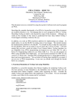
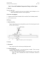
EE128 Fall 2008
University of California, Berkeley
Lab 4
Rev. 1.00
Lab 4: Inverted Pendulum Compensator Design via State Space
I. Objective
The goal of this lab is:
a. To design a controller using state space (modern) control techniques so as to
balance the pendulum about the vertical equilibrium.
II. Software and equipment
1. Computer with MATLAB, Simulink, WinCon and Real Time Workshop installed.
2. ee128 student account
III. Theory
1. Model of the Plant
Figure 1 below shows the inverted pendulum system's free body diagram from the
previous lab for reference.
Figure 1. Pendulum system free body diagram [5].
IV. Prelab
1. Plant model
From your previous lab, write down your final plant model.
2. Controller design [4]
As you deduced from lab 3, your open-loop plant is unstable. There are many
methods to controller design via state space:
1. If you know the desired location of closed loop poles, you can use the
“place” or “acker” command (acker stands for Ackerman’s Formula) in
MATLAB.
EE128 Fall 2008
University of California, Berkeley
Lab 4
Rev. 1.00
2. Another option is to use the “lqr” (Linear Quadratic Regulator) function.
This will give you the optimal controller (under certain assumptions called
the controllability criterion, check your textbook for more details). We
will be using this approach to pick a controller.
The LQR function allows you to choose two parameters, R and Q, which
will balance the relative importance of the input and state in the cost
function that you are trying to optimize (type “help lqr” in MATLAB for
more details).
The simplest case is to assume R really small (say 3e-4) and Q = C’*C.
Based on this approach, write a simple MATLAB m-script that gives you
the values of the feedback based on your plant model and LQR.
However, your controller gains are in V/m and V/rad. Convert these to
V/cm and V/degree. Then, implement this controller in lab. BEFORE
YOU IMPLEMENT THE CONTROLLER, MAKE SURE YOU
UNDERSTAND THE CONTROLLER BLOCK DIAGRAM YOU
OBTAINED FROM YOUR TA!
V. Lab
CAUTION: DO NOT TRANSFER DATA TO AND FROM THE WINDOWS 98
MACHINE.
THIS MACHINE SHOULD NOT BE PUT ON THE EECS
NETWORK!
0. Sign up for a 1-hour time slot with the TA.
1. Controller Implementation
The TA will provide you with a template for controller implementation, insert the
gains from your LQR at the appropriate place.
VI. Revision History
Semester and Revision
Summer 2008
Rev. 1.00
Author(s)
Bharathwaj Muthuswamy
Comments
1. Formatted writeup into
different sections.
2. Typed up solutions
VII. References
1. Franklin, Gene F., Powell, David J. and Emami-Naeini Abbas. Feedback Control
of Dynamic Systems. 5th Edition. 2006, Prentice-Hall Inc.
2. UCSB course ECE147B: Digital Control Systems Theory and Design. Available
online: http://www.ece.ucsb.edu/~roy/cgi-bin/makepage.pl?nav=course_147b
June 27th 2008.
3. Quanser Consulting Inc. Self Erecting IP User’s Manual, 1996.
4. Control Tutorials for MATLAB. Available Online:
http://www.ee.usyd.edu.au/tutorials_online/matlab/examples/pend/invpen.html
June 27th 2008