1
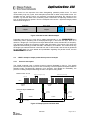
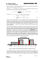
Application Note 038
CC1100/CC2500 – Wake-on-Radio
By E. Syvertsen, S. Namtvedt
Keywords
• CC1100
• CC2500
• Wake-on-Radio
1
• Ultra low-power
• Implementation example
Introduction
The low cost, highly integrated multichannel CC1100/CC2500 RF transceiver
offers Wake-on-Radio (WOR) functionality
intended for ultra low-power wireless
applications. By using this feature for
automated low-power RX-polling the user
obtains an attractive starting point for
implementing power-saving applications
for ultra low-power systems.
CC1100/CC1150DK
and
CC2550DK respectively.
CC2500/
The WOR examples are designed as
primitive wireless remote control systems,
whose intention is to provide an insight
into important considerations when using
the WOR functionality. It is demonstrating
a packet bursting transmitter and a Wakeon-Radio receiver.
This application note outlines code
examples taking advantage of the Wakeon-Radio functionality featured by the
CC1100/CC2500 chip, which are part of the
SWRA055
Page 1 of 14
Application Note 038
Table of Contents
KEYWORDS.............................................................................................................................. 1
1
INTRODUCTION............................................................................................................. 1
2
ABBREVIATIONS........................................................................................................... 2
3
WAKE-ON-RADIO (WOR).............................................................................................. 3
3.1
WOR PRICIPLES ........................................................................................................ 3
3.2
WOR AND CC1100/CC2500..................................................................................... 3
3.2.1
WOR without auto sync ....................................................................................................4
4
WOR EXAMPLES USING CC1100/CC2500.................................................................. 6
4.1
GENERAL DESCRIPTION OF EXAMPLES ......................................................................... 6
4.2
“WOR” EXAMPLE: SIMPLE PACKET BURST PROTOCOL EXAMPLE .................................... 7
4.2.1
Protocol description .........................................................................................................7
4.2.2
Timing calculations ..........................................................................................................8
4.3
“WOR-ACK” EXAMPLE: PACKET BURST PROTOCOL WITH ACK .................................... 10
4.3.1
Protocol description .......................................................................................................10
4.3.2
Timing calculations ........................................................................................................11
4.4
RUNNING THE EXAMPLES .......................................................................................... 12
5
GENERAL INFORMATION .......................................................................................... 13
5.1
DOCUMENT HISTORY................................................................................................ 13
5.2
DISCLAIMER ............................................................................................................. 13
5.3
TRADEMARKS .......................................................................................................... 13
5.4
LIFE SUPPORT POLICY ............................................................................................. 13
6
ADDRESS INFORMATION .......................................................................................... 14
2
Abbreviations
ACK
CRC
EB
EM
FS
GDO
MCU
RF
RSSI
RX
SPI
TX
WOR
XOSC
Acknowledgment packet
Cyclic Redundancy Check
Evaluation Board
Evaluation Module
Frequency Synthesizer
General Data Output
Microcontroller Unit
Radio Frequency
Received Signal Strength Indicator
Receive (mode)
Serial Peripheral Interface
Transmit (mode)
Wake-on-Radio
Crystal oscillator
SWRA055
Page 2 of 14
Application Note 038
3
3.1
Wake-on-Radio (WOR)
WOR priciples
For many battery operated (point-to-point) communication systems without the need of
constant throughput, but with strict demands of power-efficiency, the simple configuration with
an “always-on” receiver and an infrequently transmitting station will in most cases not fulfill
the desired power budget. By using the principle of receive mode (RX) polling, the reduction
of the RX duty cycle obtained makes low-power applications feasible, especially in
asymmetric systems where all units do not have equal requirements for low power
consumption. In addition, to minimize the power consumption, it is a good idea to put the
radio in a power-saving sleep state in between the RX polling periods by disabling all
functionality that is not necessary at that time.
The advantage with WOR is that the RX polling is fully automated by the radio and there is no
need for the microcontroller (MCU) to interfere (strobe RX commands). This means that also
the MCU can stay in power-down mode and further save power while waiting for a packet.
The MCU will only have to wake up when the radio actually detects a packet – it only has to
Wake-on-Radio activity. This is the reason WOR is a useful feature for power-saving
applications.
3.2
WOR and CC1100/CC2500
The Wake-on-Radio functionality of CC1100/CC2500 enables it to stay in a power-saving
SLEEP state and periodically wake up from deep sleep and listen for incoming packets in RX
without microcontroller interaction. The programmable wake-up period is controlled by a
WOR timer, run by an internal RC oscillator. This implies that the RC oscillator must be
enabled before the WOR strobe command can be used.
The radio’s configurable GDO pins are used to signal the interrupts intended for the MCU on
the desired event. For instance, if a sync word is detected during the RX period, the
CC1100/CC2500 can trigger an interrupt to wake up the MCU. The MCU can then make a
decision on what to do next; e.g. switch to TX and send an ACK or, if the CRC of the received
packet failed, continue in WOR mode (go back to SLEEP). In the latter case, after a packet
has been received, the radio will always go to the IDLE state. That means that if it is desirable
to continue in WOR mode, the MCU manually has to strobe another WOR command on the
SPI.
If no sync word is detected while in RX, a programmable RX timeout will make the chip
automatically return to sleep mode and continue in WOR mode without interrupting the MCU.
The Wake-on-Radio functionality may also be used in combination with CC1100/CC2500 ’s
RX_TIME_RSSI function. This function will perform an initial RSSI level measurement when
entering RX mode, and if the RSSI value does not exceed a programmable threshold, the RX
will terminate immediately and return to SLEEP – still in WOR mode. This function can reduce
the time in RX and contribute to lower power consumption if no signal is present.
The CC1100 offers two different methods of using WOR – with or without the automatic
synchronization feature, while CC2500 offers only WOR without autosync. This application
note will only look at WOR applications not using autosync.
SWRA055
Page 3 of 14
Application Note 038
3.2.1
WOR without auto sync
The simplest way to utilize WOR is when a transmitter continuously “bursts” packets at a
fixed interval. In this case, by configuring the receiver to wake up regularly to listen for a
packet, it is not necessary to use the autosync feature.
The frequency of the low-power RC oscillator controlling the WOR timer varies with
temperature and voltage supply. To keep this frequency as accurate as possible, the RC
oscillator is calibrated when the crystal oscillator (XOSC) is running and the radio is not in the
SLEEP state. The clock used by the WOR timer is then a divided XOSC clock. When the
radio enters the SLEEP state, the RC oscillator will use the last valid calibration result.
The time when CC1100/CC2500 wakes up from the SLEEP state and the time when the radio
is starting RX mode are denoted as EVENT0 and EVENT1 respectively. The course of events
is shown in figure 1. The wake-up interval, shown as tEvent0 in figure 1, i.e. the time between
two consecutive EVENT0s and also two consecutive EVENT1s, is configured with the
WOREVT registers.
tRx_time
RX
tRx_time
SLEEP
EVENT0 EVENT1
RX
EVENT0 EVENT1
tEvent0
tEvent1
SLEEP
t
tEvent0
tEvent1
Figure 1: Wake-on-Radio procedure
It is important to notice that the time between an EVENT0 and the following EVENT1 cannot
be set too short. Provided that the XOSC is powered down while the radio is in SLEEP, there
must be enough time for the XOSC to start after the wake-up. If automatic calibration of the
frequency synthesizer when entering RX is enabled, tEvent1 must be set long enough to also
finish the calibration of the frequency synthesizer before RX starts. The tEvent1 timer is
configurable through the WORCTRL register.
In order to ensure that a valid sync word is detected by the WOR receiver when using a
packet bursting wake-up protocol, i.e. packets are repeatedly sent with a fixed time interval, it
is important to set the timeout for sync word search in RX properly (denoted tRx_time in figure
1). The timeout must be greater than the interval between transmitted packets. If this criterion
is not fulfilled, the receiver might, in worst case, end up polling in between sync words,
missing out on all the packets. This subject will be further illustrated in the protocol
description of the “WOR” example.
An overview of the principal WOR related registers for the CC1100/CC2500 is found in table 1.
SWRA055
Page 4 of 14
Application Note 038
Table 1: WOR related registers
Register and field name
Description
IOCFG2.GDO2_CFG[5:0]
GDO2, GDO1, and GDO0 output pins configuration respectively.
At least one GDO signal should be used to provide Wake-onRadio interrupts to the MCU.
IOCFG1.GDO1_CFG[5:0]
IOCFG0.GDO0_CFG[5:0]
PKTCTRL1.WOR_AUTOSYNC
(CC1100 only)
Automatically synchronize the WOR timer to the received packet
in Wake-on-Radio mode. If enabled, the timer will automatically
reset the WOR timer when a sync word is detected. The auto
sync function is not discussed in this application note.
MCSM2.RX_TIME[2:0]
Timeout for sync word search in RX. The timeout is relative to
the programmed EVENT0 timeout. For relation with tRx_time, see
below.
MCSM0.XOSC_FORCE_ON
Force the XOSC to stay on in the SLEEP state. Normally not set
with the intention of minimizing power consumption when in
SLEEP, but may be used when reduced wake-up time is
necessary.
WOREVT1.EVENT0[15:8]
High and low byte of the EVENT0 timeout register configuring
the RX polling interval. See formula for tEvent0 below.
WOREVT0.EVENT0[7:0]
WORCTRL.RC_PD
Powers down the RC oscillator. Must be set to 0 to enable the
RC oscillator for WOR applications.
WORCTRL.EVENT1[2:0]
EVENT1 timeout. Configures the number of RC oscillator clock
periods to wait after EVENT0 before EVENT1 should occur (see
data sheet). Time for potential crystal stabilization and/or
calibration of the frequency synthesizer must be considered if
XOSC
has
been
turned
off
while
in
SLEEP
(MCSM0.XOSC_FORCE_ON) or auto calibration is enabled
(MCSM0.FS_AUTOCAL).
WORCTRL.WOR_RES[1:0]
Controls the time resolution of EVENT0 and other WOR settings.
See data sheet for possible resolutions.
MCSM0.FS_AUTOCAL[1:0]
Configures whether/when to perform automatic calibration of the
frequency synthesizer between state transitions.
MCSM1.RXOFF_MODE[1:0]
Selects the next state after finishing packet reception.
MCSM1.TXOFF_MODE[1:0]
Selects the next state after finishing packet transmission.
The relations between timeout values and register values for some of the registers in table 1
are given by the following expressions:
RX polling interval:
t Event 0 =
750
⋅ EVENT 0 ⋅ 2 5⋅WOR _ RES
f xosc
(1)
Sync word search timeout while in RX:
t Rx _ time = t Event 0 2 ( RX _ TIME +3+WOR _ RES )
⇒
12.5%
2
( RX _ TIME +WOR _ RES )
(duty cycle, WOR)
SWRA055
, RX _ TIME < 7
(2)
Page 5 of 14
Application Note 038
For MCSM2.RX_TIME = 7 = 1112, the radio will stay in RX until a packet has been received,
i.e. no actual timeout. Please see the CC1100/CC2500 data sheet for descriptions of the other
registers.
4
WOR examples using CC1100/CC2500
4.1
General description of examples
The two WOR examples described in this application note can be considered as
implementations of the same simple control system for a radio-controlled object. The system
is modeled as a simplex system with a transmitting remote control sending packets with
control commands to the remotely controlled receiving object. WOR is used to reduce power
consumption at the receiver side. Since both examples are implementations of the same
remote control system, they are very similar, but they are using different protocols. The first
and most primitive example is implemented as a purely simplex system with no transmission
error control. The transmitter is set to burst a fixed number of packets relying on one of them
being detected by the WOR receiver. The second example can be considered as an
improvement of the first one, because of its expansion to also include ACKs from the receiver
to verify each received packet.
Even if CC1100/CC2500 is a multi-channel RF transceiver, both examples utilize only a single
channel. Please note that the examples are not supposed to be an ideal, complete example
implementation of a remote control system. Their main purpose is to serve merely as a
demonstration of how to use the WOR functionality of CC1100/CC2500. Because of this, some
aspects are left out for better illustrating WOR.
The example code is written for two SmartRF®04EB (Evaluation Boards) using the on-board
Silicon Labs C8051F320 MCU together with CC1100/CC2500EM. One evaluation board (EB) is
configured to be the remote control (TX unit), and the other as the remotely controlled object
(RX/WOR unit). The joystick position on the remote control is displayed on the LCD of the
remotely controlled EB. A system setup is modeled in figure 2.
CC2500EM
CC2500EM
CC2500
CC2500
Remote
control
(TX unit)
SPI
SPI
RF link
MCU
MCU
Joystick
LCD
SmartRF ®04EB
SmartRF ®04EB
Remotely
controlled
object
(RX/WOR unit)
Figure 2: System setup for both examples showing CC2500
In order to achieve a low-latency remote control, the response time of the system must be
sufficiently small. For this system, an RX polling interval (tEvent0) of 300 ms has been set as an
SWRA055
Page 6 of 14
Application Note 038
upper bound on the response time when disregarding potential packet errors. To avoid
unnecessarily long duty cycles, both examples operate with a rather small packet format. It is
possible that the remote control only transmits commands describing the changes at the
controls, e.g. the new state of the controller joystick, information not requiring more than one
byte of data payload per packet. Thus the examples will use the 1-byte fixed length packet
format shown in figure 3.
Preamble
Sync word
4 bytes
4 bytes
Data
payloa
d
1 byte
CRC
2 bytes
Figure 3: Packet format in WOR example
Preamble bytes and sync word will be added automatically by the CC1100/CC2500 when
transmitting. When operating with a fixed payload length, in this case one byte, there is no
need for a length byte. The optional one-byte address field is also excluded due to simplicity.
The data byte contains the necessary joystick state information. The last two CRC bytes are
appended automatically provided that CRC calculations are enabled. This means that only
the single byte marked with blue is fetched from the TX FIFO buffer, and the rest is generated
by the radio itself. For more details and possibilities regarding the packet format, see the
CC1100/CC2500 data sheets.
4.2
“WOR” example: Simple packet burst protocol example
4.2.1
Protocol description
The “WOR” example uses a simplex protocol scheme illustrated in figure 4. This simple
protocol does not provide any form for ACK confirming a received packet, and packet traffic is
therefore solely uni-directional. Because of its simplicity, and despite its unreliability, the
protocol is a fitting example illustrating the main concepts of using WOR.
Remote control: TX unit
tPacket_burst (> tEvent0)
tPacket_interval (< tRx_time)
IDLE
IDLE
Joystick
event
Controlled object: RX/WOR unit
RX
RX
RX
Potential
RX timeout
Ev0 Ev1
tEvent0 = 300 ms
Potential
RX timeout
SLEEP
SLEEP
SLEEP
Ev0 Ev1
tRx_time = 1.17 ms
t
Detected
packet
Detected
packet
Joystick
event
Missed packet
IDLE
IDLE
TX TX
Ev0 Ev1
t
Figure 4: Example protocol without ACK
SWRA055
Page 7 of 14
Application Note 038
In this example, the receiver is configured to wake up and perform an RX poll searching for
transmitted packets every 300 ms to obtain a suitably low response time. Upon any change of
state of the remote control’s joystick, the transmitter initiates a burst by sending a fixed
number of identical packets. To make sure the receiver has a chance to acquire one of the
packets, the burst durability cannot be less than the time spacing between two subsequent
RX periods (tPacket_burst > tEvent0). This will ensure that at least one RX poll period will occur
during the wake-up burst period.
It is also important that the receiver’s RX period lasts at least as long as the entire packet
interval (tRx_time > tPacket_interval) to ensure that at least one incoming sync word will coincide
with the receiver’s RX poll period. If this is not fulfilled the receiver might risk start listening
right after a sync word has been transmitted and stop listening right before the subsequent
sync word is sent and as a consequence miss out on the whole burst of packets. Please note
that if the receiver is detecting a sync word right before the RX is timing out it will stay in RX
until the end of the packet, potentially extending the duty cycle, like illustrated with the last RX
poll in figure 4.
By looking at figure 4 it may seem like the receiver goes back to the SLEEP state
automatically after receiving a packet. This is not correct. When a packet has been received,
the radio switches to the IDLE state. The MCU should have been programmed to receive an
interrupt whenever the radio detects a valid sync word, and also take care of what to do next
after the radio has been awoken from WOR mode. For this protocol example, the MCU
checks the CRC status of the packet, parses the payload, and regardless of the result puts
the CC1100/CC2500 back to SLEEP as soon as possible continuing the Wake-on-Radio mode
in order to minimize the power consumption.
4.2.2
Timing calculations
The transmitted packets within a wake-up packet burst should be uniformly spaced in time,
something that can be achieved by using a programmable timer in the MCU to trigger off
each packet. To reduce the remote control’s TX duty cycle and subsequently the power
consumption, the CC1100/CC2500 enters the IDLE state in between each packet. Worth noting
is that increasing the IDLE period of the transmitter by increasing the packet interval will
reduce the TX duty cycle. But to still fulfill the need of having an RX polling period at least the
size of the packet interval, the RX duty cycle has to increase correspondingly, increasing the
RX duty cycle. These considerations have to be adjusted according to specifications of the
application.
As a system specification for this example, a limit of 0.5% RX duty cycle has been set at the
receiver as maximum, while still minimizing the power consumption on the transmitter side to
a certain degree.
Firstly, the EVENT0 register value corresponding to a 300 ms RX poll interval must be
calculated. For this relatively short time interval, setting WOR_RES = 0 gives a fitting
resolution. By using equation (1) and assuming a 26.0 MHz crystal (used on
CC1100/CC2500EM), EVENT0 can be determined:
300 ms =
750
⋅ EVENT 0 ⋅ 2 5⋅0
26.0 MHz
⇒ EVENT 0 = 10400 = 28 A016
(3)
This word is split into the two byte-sized registers WOREVT1 and WOREVT0, which constitute
the high and low byte of the EVENT0 timeout register, i.e. WOREVT1=2816 and WOREVT0=A016.
The transmitter is configured for operating at a bit rate of 250 kbps, which gives a necessary
TX time of at least 352 µs to send the 88 bit long packet. To achieve less than 0.5 % RX duty
cycle the timeout for the sync word search in RX has to be less than
SWRA055
Page 8 of 14
Application Note 038
300 ms * 0.5 / 100 = 1.5 ms. These two values (352 us and 1.5 ms) represents the theoretical
absolute minimum and maximum value for tRx_time.
Having the WOR_RES decided to be 0 (equation (3)), an appropriate RX timeout within the
duty cycle limit may be found by using the given equation (2):
t Rx _ time (duty cycle) =
12.5 %
2
( RX _ TIME + 0 )
< 0.5 % ⇒ RX _ TIME ≥ 5
(4)
Choosing MCSM2.RX_TIME=5=1012 corresponds to an RX timeout of:
t Rx _ time = 300 ms 2 (5+3+0) = 300 ms 256 = 1.172 ms
⇒
(5)
12.5 %
= 0.391 % (duty cycle, WOR)
2 ( 5+ 0 )
With a known RX timeout period we are able to determine the TX packet interval. A packet
interval of 1.0 ms would make a 0.172 ms difference with the RX timeout, and should
constitute sufficient percentual margin for coping with possible oscillator frequency offsets
due to temperature and voltage variations. With 1.0 ms packet interval, the transmitter in the
“WOR” example transmits 305 packets for each wake-up burst, meaning tPacket_burst = 305 *
1.0 ms = 305 ms > tEvent0 = 300 ms. The extra margin is added because of possible oscillator
and timer variations.
The packet interval decides the TX duty cycle, in this case a TX duty cycle of (352 µs / 1000
µs) * 100% = 35.2%. Another important aspect is that the packet spacing, the time from the
end of one packet to the start of the next one, has to be sufficiently large to account for the
necessary time for state transitions between IDLE and TX and also possibly any frequency
synthesizer (FS) calibrations. This means that in this example the CC1100/CC2500 will not
have 1000 µs – 352 µs = 648 µs in IDLE for each packet sent – the delays between state
transitions have to be subtracted. If we for this simple packet burst protocol assume it is only
necessary with an initial manual FS calibration before the burst starts and there is no
calibration prior to each packet within the burst, the IDLE to TX transition will take 88.4 µs and
the conversely TX to IDLE takes 0.1 µs without calibrations. This leaves a theoretical time of
559.5 µs in IDLE state per packet sent. All these time values are assuming a 26.0 MHz
crystal. An illustration of the packet burst timing is shown in figure 5.
559.5 µs
0.1 µs
352 µs
88.4 µs
559.5 µs
0.1 µs
352 µs
88.4 µs
> 721 µs
Figure 5: Timing for the simple packet burst example, showing start of burst
On the Wake-on-Radio side, the receiver is recommended to enable automatic calibration of
the frequency synthesizer whenever switching from IDLE to RX. Configuring the
MCSM0.FS_AUTOCAL register bits equal to 012 does this. In most cases, including this
example, the XOSC_FORCE_ON bit of the MCSM0 register is left unset, turning off the XOSC
SWRA055
Page 9 of 14
Application Note 038
when entering SLEEP state during WOR mode to reduce the power consumption. When the
radio wakes up to IDLE state at EVENT0, there must be enough time for the crystal to start
up and stabilize (typically 300 µs) and for the calibration of the frequency synthesizer
(typically 809 µs) before the RX can begin at EVENT1; in total a wait period of over 1.1 ms.
This implies the WORCTRL.EVENT1 bits for this case must be set equal to 1112, configuring
tEvent1 = 1.38 ms (with a 26.0 MHz crystal).
4.3
4.3.1
“WOR-ack” example: packet burst protocol with ACK
Protocol description
The “WOR-ack” example is using a similar protocol as the “WOR” example, but this has been
extended by including support for acknowledge (ACK) of each received packet. Upon a
joystick movement, the remote control EB starts bursting identical packets until it gets an ACK
back from the receiving EB. This means that there, in contrast to the previous example, is no
fixed number of packets in a burst. In order for the remote control to be able to detect the
acknowledgement packets that will make it halt the packet burst, it has to switch to RX for a
short period in between each packet. In addition the remotely controlled EB (still referred to
as the receiver since the data traffic still is simplex) will now have to transmit an ACK in
response of a received packet. The ACK is sent immediately after a valid packet has been
received. If the receiver is awoken from the Wake-on-Radio mode by receiving an invalid
packet (wrong packet length, containing CRC error etc.), no reply will be sent. The MCU will
in either case make the receiver go back to WOR mode.
Due to protocol changes, the WOR EB will be programmed to automatically switch to the
FSTXON state when a packet has been received instead of to the default IDLE state
(MCSM1.RXOFF_MODE = FSTXON). FSTXON is a state where the frequency synthesizer is
left on, ready to start transmitting. The transmission starts very quickly after the STX
command strobe has been issued. When the WOR EB has received a valid sync word and
the MCU has been made aware of it, the MCU will check the CC1100/CC2500 ’s RX FIFO for
content and check any packet’s validity. Meanwhile the receiving unit will be waiting in
FSTXON state, prepared to rapidly transmit an ACK. If there is no need to send an ACK, the
MCU will issue the SIDLE command strobe to go back to IDLE state, and then the SWOR
strobe, continuing in WOR mode.
Almost similarly, the transmitter will automatically switch to RX instead of IDLE at the end of
each packet transmission (MCSM1.TXOFF_MODE = RX). This is necessary to listen for any
ACKs, while at the same time being time saving compared to a manual SRX strobe. The
receiver is ACKing the packets with a payload byte equal to the inverted command byte
received. The remote control parses the ACK packet in order to verify that it is an ACK for the
current joystick position. If it is an ACK that has been received, the ongoing packet burst is
halted. If no ACK is detected, an RX timeout will put the transmitter back to IDLE. For the
“WOR-ack” example it is also implemented an upper limit of packets to send without getting
any ACK, functioning as a packet burst timeout preventing the transmitter to endlessly
transmit without any purpose. In theory, the transmitter should never have to transmit more
than 305 packets in a burst, as discussed in section 4.2.2. However, when running the
application example, one will occasionally experience that more than 305 packets are
transmitted before an ACK is received. There are two possible reasons for why this might be
happening:
1. The receiver was in RX while the packet was transmitted, but something disturbed
the signal so that the radio was not able to receive the packet properly.
2. The receiver did receive the packet and transmitted an ACK, but the transmitter did
not receive the ACK.
This again, can be due to two different things:
• Same as #1 above
SWRA055
Page 10 of 14
Application Note 038
•
4.3.2
The RX timeout on the transmitter was too short due to the RC Oscillator bug
on CC2500. Please refer to CC2500 Errata Note 001.
Timing calculations
For the “WOR-ack” example some of the timing properties are kept equal to those used for
the “WOR” example. At the receiver side the polling period of 300 ms and the RX duty cycle
are preserved, still with an RX timeout of 1.172 ms. Accordingly, the transmitter still operates
with a packet interval of 1.0 ms. The FS calibration routines are also maintained; the
transmitter only performs a calibration at the start of each packet burst, and the receiver
performs a calibration prior to every RX polling period.
Whenever the receiver detects a packet, the transition from RX to FSTXON will take 9.6 µs.
The transmitting CC1100/CC2500 will almost simultaneously execute the 21.5 µs lasting
transition from TX to RX. After a small delay in software (RX FIFO must be checked for
packet, data processing etc.), the MCU on the receiving EB will have decided whether to
send an ACK or not. Refer to figure 7 for protocol timing details. This delay is expected to
clearly exceed the difference in transition time of almost 12 µs. The RX timeout of the
transmitter must therefore be set long enough to still wait in RX when the sync word of a
potential ACK is sent. To transmit 4 bytes of preamble plus 4 bytes of sync word at 250 kbps
takes 256 µs. Adding certain delay margins for propagation delay and processing time sets
the RX timeout at the transmitter to 325 µs. A sketch of this can be found in figure 6. It would
also have been possible to let the RX never time out, i.e. wait in RX for a packet until the 1.0
ms timer triggers off the next packet to be transmitted. This would of course have increased
the duty cycle of the transmitter.
0.1 µs
325 µs
21.5 µs
352 µs
88.4 µs
213 µs
0.1 µs
325 µs
21.5 µs
352 µs
88.4 µs
> 721 µs
Figure 6: Remote control timing for the packet burst with ACK listening
The introduction of ACK to this simple protocol causes an increase of duty cycle on both
sides. In addition to the 35.2% TX duty cycle, the transmitter will experience an RX duty cycle
of 325 µs / 1.0 ms * 100% = 32.5%. The price of ACKing is not as high for the receiver as for
the transmitter; the CC1100/CC2500 with WOR will only have an extra TX duty cycle of
352 µs / 300 ms * 100% = 0.117% at maximum together with the already 0.391% RX duty
cycle.
SWRA055
Page 11 of 14
ACK
Detected pkt
Application Note 038
FSTXON
0.1 µs
352 µs
9.6 µs
1.17 ms
Figure 7: Receiver timing for the Wake-on-Radio with ACK reply
4.4
Running the examples
For a description of how to load the programs into your SmartRF®04EB, please refer to the
publication “CC1100/CC2500 Examples Libraries User Manual” found on the Chipcon
website, http://www.chipcon.com. Together with the .hex files, the source code with
comments will be found.
Before running the programs, EB units must be configured to either be the transmitter unit
bursting packets or the receiver unit using Wake-on-Radio. This is done in the setup menu by
moving the joystick sideways – move it left to choose TX unit and right for RX/WOR unit.
Push the S1 button to confirm your choice. After the unit has been configured, the yellow LED
will turn on.
If the TX unit is selected, you are now able to push the joystick button or move it up, down,
left or right. This will start the packet burst and the number of packets sent in the burst will be
displayed on the LCD. For the “WOR” example, the number of packets in a burst is constant,
but for the “WOR-ack” example the burst will continue until an ACK has been received or a
timeout occurs. The blue LED will toggle for each packet sent. For the “WOR-ack” example
the green LED will toggle every time a valid ACK has been received, and the red LED will
toggle for non-valid packets received.
If the RX unit is selected, it will automatically enter the Wake-on-Radio mode, waiting for
packets. For the “WOR” example, every time a packet has been detected and the radio is
sending an interrupt signal to the MCU, the blue LED will toggle. For the “WOR-ack” example
the blue LED will only be toggled when it is transmitting an ACK. For both examples, a toggle
of the green LED will indicate a packet has been received successfully, and the red LED will
toggle whenever an invalid packet has been received. The LCD will continuously display how
many valid packets have been received together with the position of the joystick on the
remote control.
Both programs can be terminated by pressing the S1 button after the setup has been done.
This will turn off the yellow LED.
SWRA055
Page 12 of 14
Application Note 038
5
5.1
General Information
Document History
Revision
1.0
5.2
Date
2005-11-22
Description/Changes
Initial release.
Disclaimer
Chipcon AS believes the information contained herein is correct and accurate at the time of this printing. However,
Chipcon AS reserves the right to make changes to this document without notice. Chipcon AS does not assume any
responsibility for the use of the described product; neither does it convey any license under its patent rights, or the
rights of others. The latest updates are available at the Chipcon website or by contacting Chipcon directly.
As far as possible, major changes of product specifications and functionality, will be stated in product specific Errata
Notes published at the Chipcon website. Customers are encouraged to sign up to the Chipcon Newsletter for the
most recent updates on products and support tools.
When a product is discontinued this will be done according to Chipcon’s procedure for obsolete products as
described in Chipcon’s Quality Manual. This includes informing about last-time-buy options. The Quality Manual can
be downloaded from Chipcon’s website.
Compliance with regulations is dependent on complete system performance. It is the customer’s responsibility to
ensure that the system complies with regulations.
5.3
Trademarks
SmartRF® is a registered trademark of Chipcon AS. SmartRF® is Chipcon's RF technology platform with RF library
cells, modules and design expertise. Based on SmartRF® technology Chipcon develops standard component RF
circuits as well as full custom ASICs based on customer requirements and this technology.
All other trademarks, registered trademarks and product names are the sole property of their respective owners.
5.4
Life Support Policy
Chipcon’s products are not designed for use in life support appliances, devices, or other systems where malfunction
can reasonably be expected to result in significant personal injury to the user, or as a critical component in any life
support device or system whose failure to perform can be reasonably expected to cause the failure of the life support
device or system, or to affect its safety or effectiveness. Chipcon AS customers using or selling these products for
use in such applications do so at their own risk and agree to fully indemnify Chipcon AS for any damages resulting
from any improper use or sale.
© 2005, Chipcon AS. All rights reserved.
SWRA055
Page 13 of 14
Application Note 038
6
Address Information
Web site:
E-mail:
Technical Support Email:
Technical Support Hotline:
http://www.chipcon.com
[email protected]
[email protected]
+47 22 95 85 45
Headquarters:
Chipcon AS
Gaustadalléen 21
N-0349 Oslo
NORWAY
Tel: +47 22 95 85 44
Fax: +47 22 95 85 46
E-mail: [email protected]
US Offices:
Chipcon Inc., Eastern US Sales Office
35 Pinehurst Avenue
Nashua, New Hampshire, 03062
USA
Tel: +1 603 888 1326
Fax: +1 603 888 4239
Email: [email protected]
Chipcon Inc., Western US Sales Office
19925 Stevens Creek Blvd.
Cupertino, CA 95014-2358
USA
Tel: +1 408 973 7845
Fax: +1 408 973 7257
Email: [email protected]
Figure 8 Wireless
10509 Vista Sorrento Parkway, Suite 420
San Diego, CA 92121
USA
Tel: +1 858 522 8500 ext.6
Fax: +1 858 552 8501
Email: [email protected]
Sales Office Germany:
Sales Office Asia:
Chipcon AS
Riedberghof 3
D-74379 Ingersheim
GERMANY
Tel: +49 7142 9156815
Fax: +49 7142 9156818
Email: [email protected]
Chipcon AS
Unit 503, 5/F
Silvercord Tower 2, 30 Canton Road
Tsimshatsui, Hong Kong
Tel: +852 3519 6226
Fax: +852 3519 6520
Email: [email protected]
Sales Office Japan
Chipcon AS
#403, Bureau Shinagawa
4-1-6, Konan, Minato-Ku
Tokyo, Zip 108-0075
Tel: +81 3 5783 1082
Fax: +81 3 5783 1083
Email: [email protected]
Chipcon AS is an ISO 9001:2000 certified company
© 2005, Chipcon AS. All rights reserved.
SWRA055
Page 14 of 14


![Hacking Medical Devices - [media.blackhat.com]](http://vs1.manualzilla.com/store/data/005931227_1-f7547ce2b3ff0825b843d9b1dbb48800-150x150.png)