1
Hacking Medical Devices for Fun and Insulin: Breaking the Human SCADA System Jerome Radcliffe On my 22nd birthday I went to the doctor, having lost 40 pounds in less than two months and an insatiable thirst. It did not take long before the doctor diagnosed diabetes; not long after that I was prescribed insulin, which I had to inject into my body 4-‐7 times a day. There, however, is an alternative method of delivery available for insulin injections where, rather than having to inject myself with a needle and syringe, I could attach an insulin pump to my body. It is not a permanent attachment, but rather uses a small needle and tubing, called an infusion set, that needs to be replaced approximately every three days. An insulin pump is a device about the size of an old-‐fashion pager that can deliver insulin doses as small as 0.25 units that can be given more constantly, where syringes are often limited to 1.0U doses given all at once. There are several advantages to using an insulin pump: you have more control over insulin delivery, more flexible shorter acting insulin can be used, and more data can be captured to help make better decisions for treatment. As a geek, the idea of this “smart” gadget being attached to me had an appeal. It allowed me to collect data which would let me make better decisions in my treatment. It also has some wireless capabilities, making data entry from an external blood glucose device easier. Another advance in technology for diabetics has been in the field of continuous glucose monitors (CGM). These use three to seven day sensors that attach to your body, these sensors then send out a wireless signal to a receiver that monitor blood sugar rates every five minutes. The combination of the insulin pump and the CGM makes me look like a super-‐dork rocking the pager from the late 90s, but it really helps me and my doctors manage my treatment better. I always joked around that on day some hacker was going to break into my pump, give me a dose of insulin that I didn’t need, which could force my blood sugar too low and result and render me unconscious after an hour. After attending a talk at Defcon in 2009 that focused on hacking smart parking meters, I began to ponder hacking into my own diabetic “smart devices.” I have a background in ham radio operation, which provides me the knowledgeable in the physical layer of wireless communication, and felt that my added years of experience in the computer security field might just allow me to pull off hacking this Human SCADA System. SCADA Connection I was researching the Stuxnet malware in my professional job I discovered one element that makes this research highly relevant to today’s environment. Looking at the SCADA and ICS systems, I was amazed to see that it was very similar in concept to what I was manually doing with my insulin pump and CGM system. Take a chemical plant for example; it has a tank of liquid or gas that it needs to keep at a stable elevated temperature and it uses a sensor that reports that temperature, and a set of heaters that are controlled by a valve to adjust the heat. When the sensor reports a temperature that is too cool, the valve can be opened to create more heat. At some point the sensor will report that the temperature is getting too hot, and the valve can be closed to reduce the heating. If the valve for the heating does not turn off, then the temperature can get too high, which, depending on the substance being heated could be dangerous. Regulating blood sugar to insulin ration if very similar to the chemical plant example; a measurement is taken of blood sugar, which should be within a certain range (90-‐
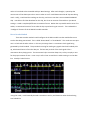
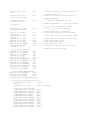
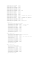
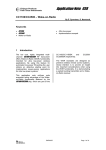
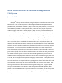
120mg/dl). If that number is too high, insulin can be given to lower that number back to the acceptable range. If too much insulin is given, then the blood sugar can get too low resulting in a condition known as hypoglycemia, which can be very dangerous as the body will start to shut down when sugar gets too low. If left untreated, hypoglycemia can lead to coma and, in extreme cases, death. When blood sugar gets too low, diabetics will often consume a high sugar drink or food to bring levels back into a healthy range. This humans system, then, is nearly identical to the chemical plant, and much like the chemical plant, my ability to regulate blood sugar is dependent on the readings given to me by my hardware. Hacking the System In SCADA/ICS environment, the concerned is about the manipulation of the sensor data and control over systems that make adjustments based on that data. Take Stuxnet for example. The research on this speculated that the malware payload manipulated how fast a centrifuge would spin, ultimately causing them to spin faster than they were designed to go, and destroying them. The Stuxnet payload also falsely reported back to operators how fast those centrifuges spun, leaving the operators to believe that the systems were operating correctly. How would this translate into the personal case with diabetics? Rather than making a centrifuge spin too fast, a malicious program could tell the insulin pump to deliver more insulin then it is programmed to do. This could result in a hypoglycemic episode. Similar to Stuxnet, a malicious program could also inject false sensor data, resulting in the diabetic making a decision based upon false data; if the sensor data was falsely reporting blood sugar as being elevated when it was not, a diabetic could administer too much insulin, which, again, would result in a potential hypoglycemic state. Recon Steps Looking at this research like a penetration test, the first step I needed to conduct was reconnaissance. I needed to collect as much data on my targets as I could. Since I was looking to target the wireless communication of both my insulin pump and CGM devices, I needed to get some information on what frequencies and modulation these devices operated on. The first place I looked was in the user manual for the devices. This often discarded document often contains a wealth of information. In my case the manual had an appendix that told me the exact frequency and modulation method that the CGM system I owned operated on (402.142mHz On-‐Off Keying), how long the packet was (76 bits), and how often transmissions occurred (once every five minutes) The insulin pump manual provided similar details (916mHz On-‐Off Keying). Another key item of information in the manual was the Federal Communication Commission (FCC) ID of the device. All wireless devices sold in the Unites States have to be cleared by the FCC, and are given a unique ID. If you take this ID to the FCC website, you can download the FCC verification documents of the device. This has detailed analysis of the transmission, including screen captures from spectrum analyzers and oscilloscopes. These devices cost tens of thousands of dollars often outside the reach of the budgets of small or individual researchers. I also spent some time looking at the website of the patent office. Searching under the name of the manufacturer, I was able to find all of the patent documents for the devices. This provided a lot of information on the devices functionality and how the devices are built. With this information, I could start to look for devices that operate on those frequencies. Arduino / RF Modules Most Radio Frequency (RF)/Wireless development kits cost thousands of dollars and I was working on a limited budget that did not allow for that type of expense. I was aware of a hardware platform called Arduino, this little microprocessor board had a simple programming language and allows a programmer to interface with a large assortment of devices and modules to perform all kinds of fun tasks. While researching for devices that operated on the frequencies of my devices I stumbled across an article that mentioned an Arduino module that worked on frequencies very close to my devices. Better yet, it was very inexpensive and readily available. This module is based on the Texas Interments CC1101 Wireless chip. This chip operates on the 315/433/868/915MHz ISM/SRD bands, which cover both of my devices. I found a source of these boards on eBay for less than $20 each. OOK Modulation After getting the CC1101 module, I needed to figure out how to configure the device to operate on the same frequency and modulation type as the devices I was using. This was much more difficult than it sounds. There are 70+ register settings for the CC1101, and even for someone with over 20 years of ham radio experience, I was a little over whelmed. One of the challenges of crossing over from computer security research to hardware hacking research is the ease of use of the devices. Most of the packages we use have manuals (or at least man pages) that have some use examples. The CC1101 manual has 108 pages, but none of it tells you how to program the device, nor does it have a simple user guide on setting it up. This was designed for the experienced electrical engineer to use, not the computer geek. One of the first settings I needed to tackle was the issue of modulation type. My years of radio experience helped me there, as On-‐Off Keying (aka OOK) is very similar to the most well known ham radio communication format, Morse code or continuous wave modulation. In this format, there are two states of modulation, On and Off. In this case, On would equate to a binary 1, and Off would equate to a binary 0. If viewed on an oscilloscope or logic analyzer, you can transcribe the signal into a binary stream. Wireless Transmission 101 There are a couple of other register settings that I was unsure of how to set, which required me to do a little more research on how these types of chips communicate. There are two parameters that are in the CC1101 manual that were unfamiliar; first is the Preamble setting, and the second is Sync Word. The Preamble setting is the very first part of a transmission that usually consists of alternating binary 1s and 0s. The function of this is to allow the receiving unit to know that a transmission is eminent. In the time that the preamble is being received, the receiver can wake up from power saving mode and adjust various gain settings to assure that the transmission can be processed properly. The CC1101 settings have this between 2 and 32 bytes in length. Sync Word is a predetermined set of bytes that are transmitted right after the preamble. On the CC1101, this is in to form of multiple hex groupings broken into a high and low word and range from 8 bytes to 32 bytes. An example would be an 8 byte Sync Word 0x1A2B. The high word would be 0x1A and the low word would be 0x2B. The function of this Sync Word would be to verify that the transmission is in the proper format, and for the receiver to know that the transmission is from a compatible known transmitter. Here is where I ran into a problem. There is nothing in the documentation about these two settings. More problematic is that the CC1101 module will not put any data into its receive buffers unless it’s matched to the Preamble and Sync Word settings. After much thought, I opened up the receiver unit of the CGM system that I own in order to see if I could determine what RF chip was being used. Luckily, I could read the markings on the chip, and it turns out that it uses an AMIS-‐52100M RF chip. I was able to find the datasheet for this chip, but it has no mention of Preamble or Sync Word settings. It used a completely different transmission format. Rather than a preamble with a series of 1s and 0s, it transmitted a series of 1s to wake the chip up and set the gain controls. This rendered the “intelligent” features of the CC1101 RF module unusable. Direct Decode Method There was another method I could configure the CC1101 module into that would allow me to see the data being transmitted. This is called “Direct Mode” or “Serial Mode”. This mode uses two pins: one is a clock and the other is data. In this two pin setup, there is a continuous clock signal being generated by the RF module. This provides the timing for reading any signals that the RF module picks up, which would come in from the data pin. The best way to think of the clock signal is like a metronome when playing music. The metronome helps a musician keep time, so they can play a note for the proper amount of time. In our case, it tells us how to read the 1s and 0s coming in on the data line. Visually it looks like this: Using this mode, I could manually decode transmissions and try and determine what the data being sent looked like. CGM Discoveries The CGM device had some known quantities that made it appealing to tackle first. It has a very small packet size (76 bits) and a high rate of transmission (once every five minutes). There was also some known data that was assured to be in the packet. The transmitter that attaches to the sensor is designed to last approximately one year. This replaceable transmitter has a unique serial identifier that has to be programmed into the receiver. This assures that the receiver is using the data from the correct sensor. The format of this unique identifier is 5 characters long, the first character being a 0 (zero) or a 1 (one). The remaining four characters are alphanumeric (0 though 9, A though Z). There should be a consistent pattern in the transmission where this identifier is located. Another factor is that the variance in the data being returned from the sensor should not change drastically every five minutes. To minimize this, data was only collected when my blood sugar was stable, as it can be highly variable at times, such as after meals. This was done to try and make the sensor transmissions as consistent as possible. After collecting several hours of data, what I found there were not consistent packets. There were some identifiable patterns in the transmissions, and the transmissions were almost always 9.0ms to 9.3ms long, and between 73 and 78 bytes in length. This indicates that the information discovered in the research was accurate. When looking at the patterns of the data stream, with very minor changes (not changing any data, only spacing limited to one clock cycle) 80 percent of the packets had the same first 21 bits. These bits do not directly translate to the unique identifier of the transmitter. There are two theories to why this data is not consistent. First, the transmitter is transmitting at low power (25 microwatts). This might make it difficult for the receiver to adjust the gain settings enough to accurately receive the signal. This theory is hard to verify, but we do know that every transmission was the same length and was detected every five minutes. If the signal was so weak to not be received properly, it would be expected that some of the transmissions would be missed or truncated, having inconsistent lengths. The second theory is that the data is getting encoded or modified before being transmitted. This is more likely, as parts of the transmission are identical enough to indicate that the identifier is in the transmission, but in a different way. Insulin Pump Discoveries The second device that I looked at was my insulin pump. There are three wireless applications that the insulin pump I own utilizes. First, there is a java based program that uses a wireless peripheral device to configure all the settings on the device. Second, there is a blood glucose meter that can communicate the results of a blood strip test to the insulin pump. This makes it more convenient for a diabetic to enter those values into the insulin pump. Third, this insulin pump also has a CGM functionality, allowing the use of a CGM sensor that works exactly the same as the stand alone CGM device mentioned above. All three use the same wireless interface on the insulin pump. From earlier research we already know the frequency (916.50mHz) and modulation (OOK). Before digging into the physical layer of the wireless transmission, I wanted to see what the log files of the configuration software had to offer for more information. In the properties file, the logging was set to NONE, which I changed to HIGH. This produced a wealth of information, including the actual messages and responses with the device. Another discovery is the use of an encoding method used before transmission of the message to the device. This encoding method lengthens the message, almost doubling the size. Curious to how this encoding method worked, I looked at the lone java library file (also known as a JAR file) that the program used in an effort to see more detail of this method. Often, companies will obfuscate these libraries to prevent easy reverse engineering. Luckily, these files were not obfuscated and were easily viewed. Being able to view these library files, it was trivial to reproduce not only the encoding method, but all of the message formats and command codes for the device. Security Concerns What does all of this information tell us though? Is there a security concern? Is there a vulnerability to exploit? In a word: maybe. Let us consider some of the known attacks that are seen in the more traditional computer security models. Replay attacks are going to be effective against these types of devices. There is no timestamp or other protection to defend against these types of attacks. Similarly, if the message format is known, and the encoding method is known, then being able to spoof the transmission might be trivial. One of the elements to all of the transmissions is the serial number of the device or the unique identifier of the device. In the case of the CGM sensors, this is transmitted in a beacon like fashion (in my device’s case, every five minutes). This would make it easy to passively discover this information. The insulin pump does not have this issue, and the serial number would have to be acquired through other means, perhaps through social engineering. Given this information, what theoretical malicious attacks could be performed? Theoretical CGM Attack Example The worst case scenario for an attack on a CGM device would be to spoof sensor data to the user making them think that their sugar is either higher or lower than it actually is. There are two ways that this can be accomplished. If the transmission format is unknown, then a replay attack can be used. Using a previously transcribed transmission from the sensor that shows a high sugar value, this could later be re-‐transmitted by the CC1101 RF module. This would cause the receiver unit to indicate a higher sugar reading then actually exists. To eliminate the legitimate sensor data from being picked up, the CC1101 can transmit garbage data at the same time that the sensor is transmitting. This would be a trivial task, as the transmissions occur at an exact time that is predictable (every five minutes). This is a dangerous situation for the diabetic, as the sugar value reported by the CGM is used to determine the amount of insulin to administer. A diabetic could be manipulated into administering more insulin then needed, potentially causing a hypoglycemic condition. There are three factors the make this attack harder then it seems. First, the range of the CGM devices is extremely limited. The transmitter would have to be within 100 to 200 feet of the CGM receiver. This limits the attacker’s ability, as they have to gain physical access the individual’s personal space to conduct the attack. Second, CGM devices often will prompt the user for a calibration measurement, which is done with a blood glucose meter. This would defeat the attacks, as intervention of this calibration test is highly unlikely. Lastly, while an attacker might be able to manipulate a diabetic to administer too much insulin, this is something that is common for a diabetic to experience. The manipulation of the sensor data would have to continue for hours to keep the user manipulated. This also reduces the likelihood of a successful attack. Theoretical Insulin Pump Attack A dangerous situation for an insulin pump user is the unknown manipulation of configuration settings as these settings are the foundation for calculating the amount of insulin that is dispensed to the user. This attack would involve the attacker purchasing the wireless peripheral needed to talk to the insulin pump. These are often found on eBay for less than one hundred US dollars, or can be purchased without the need for a prescription brand new from medical supply retailers. The task of discovering the command codes for the insulin pump and message format are fairly simple. Google shows that this information has been published in multiple places, even though the manufacturer has not disclosed them directly. An attack would need little time, as the changing of a configuration setting would only take moments. For example, the setting that controls the ratio of insulin given at meal time could be altered. If a user is suppose to get 1 Unit of insulin per 5 grams of carbohydrate eaten, the attack could change that to 1 unit of insulin per 3 grams of carbohydrates eaten. This is a significant enough difference to cause a diabetic to become hypoglycemic roughly 60 to 90 minutes after eating. Again, there are some factors that limit this attack. First, like the CGM devices, the range on an insulin pump’s wireless ability is limited to 100 to 200 feet. Unlike the CGM attack, this attack only takes seconds though. Second, the attacker would have to acquire the serial number to the insulin pump target for the attack to work. This cannot be done wirelessly, and would probably require physical access to the device. This is not impossible, but does limit the potential for attack. Future Security Concerns Although all these potential attacks are serious, diabetics still have a significant human element in the decision making process of delivering their medication. A person takes the data provide by the CGM system and blood glucose meter, along with other variables to determine the proper amount of insulin to administer. There are security risks in manipulating some of the data the person uses, but ultimately an attacker cannot directly manipulate the amount of insulin given. The industry has plans to remove the human intervention from this equation though. The Juvenile Diabetes Research Foundation (JDRF) is pushing a campaign called the “Artificial Pancreas Project”. The goal of this would be to “close the loop” between the CGM monitoring systems and the insulin pump delivery system. To go back to our SCADA example, rather than a human monitoring the temperature and adjusting the heat, replace the human with a computer program. This would allow for the automatic adjustment of the heat rather than waiting for a human to react. A closed loop insulin delivery system would take the sensor readings and adjust insulin delivery based upon a computer program. Given the attack scenarios given above, the potential for harm would be greater in an automated system. Less human involvement would also mean less human oversight of the process. The Artificial Pancreas Project is defiantly a step in the right direction for the treatment of diabetes. The security, however, around the devices should be looked at more closely and it should be done not as an afterthought. It should be a priority from the start of development until the end of production. Future Research Paths This research on wireless security on these medical devices has only scratched the surface of what vulnerabilities exist. More can be done to protect these devices and their data from potential exploit. The scope of the research can be expanded as well. These RF chips and wireless formats are in a wide array of devices, from wireless toys, medical devices, industrial equipment, and SCADA hardware. With a little bit of knowhow, a little bit of hardware and some curiosity, a whole new world of research is waiting to be done. Appendix A: CC1101 Registry Settings // CC1101 CONFIG REGSITER
#define CC1101_IOCFG2
#define CC1101_IOCFG1
#define CC1101_IOCFG0
#define CC1101_FIFOTHR
#define CC1101_SYNC1
#define CC1101_SYNC0
#define CC1101_PKTLEN
#define CC1101_PKTCTRL1
#define CC1101_PKTCTRL0
#define CC1101_ADDR
#define CC1101_CHANNR
#define CC1101_FSCTRL1
#define CC1101_FSCTRL0
#define CC1101_FREQ2
#define CC1101_FREQ1
#define CC1101_FREQ0
#define CC1101_MDMCFG4
#define CC1101_MDMCFG3
#define CC1101_MDMCFG2
#define CC1101_MDMCFG1
#define CC1101_MDMCFG0
#define CC1101_DEVIATN
#define CC1101_MCSM2
configuration
#define CC1101_MCSM1
configuration
#define CC1101_MCSM0
configuration
#define CC1101_FOCCFG
#define CC1101_BSCFG
#define CC1101_AGCCTRL2
#define CC1101_AGCCTRL1
#define CC1101_AGCCTRL0
#define CC1101_WOREVT1
#define CC1101_WOREVT0
#define CC1101_WORCTRL
#define CC1101_FREND1
#define CC1101_FREND0
#define CC1101_FSCAL3
#define CC1101_FSCAL2
#define CC1101_FSCAL1
#define CC1101_FSCAL0
#define CC1101_RCCTRL1
#define CC1101_RCCTRL0
#define CC1101_FSTEST
#define CC1101_PTEST
#define CC1101_AGCTEST
#define CC1101_TEST2
#define CC1101_TEST1
#define CC1101_TEST0
//CC1101 Strobe commands
#define CC1101_SRES
#define CC1101_SFSTXON
(if MCSM0.FS_AUTOCAL=1).
0x00
0x01
0x02
0x03
0x04
0x05
0x06
0x07
0x08
0x09
0x0A
0x0B
0x0C
0x0D
0x0E
0x0F
0x10
0x11
0x12
0x13
0x14
0x15
0x16
//
//
//
//
//
//
//
//
//
//
//
//
//
//
//
//
//
//
//
//
//
//
//
GDO2 output pin configuration
GDO1 output pin configuration
GDO0 output pin configuration
RX FIFO and TX FIFO thresholds
Sync word, high INT8U
Sync word, low INT8U
Packet length
Packet automation control
Packet automation control
Device address
Channel number
Frequency synthesizer control
Frequency synthesizer control
Frequency control word, high INT8U
Frequency control word, middle INT8U
Frequency control word, low INT8U
Modem configuration
Modem configuration
Modem configuration
Modem configuration
Modem configuration
Modem deviation setting
Main Radio Control State Machine
0x17
// Main Radio Control State Machine
0x18
// Main Radio Control State Machine
0x19
0x1A
0x1B
0x1C
0x1D
0x1E
0x1F
0x20
0x21
0x22
0x23
0x24
0x25
0x26
0x27
0x28
0x29
0x2A
0x2B
0x2C
0x2D
0x2E
//
//
//
//
//
//
//
//
//
//
//
//
//
//
//
//
//
//
//
//
//
//
0x30
0x31
// Reset chip.
// Enable and calibrate frequency synthesizer
Frequency Offset Compensation configuration
Bit Synchronization configuration
AGC control
AGC control
AGC control
High INT8U Event 0 timeout
Low INT8U Event 0 timeout
Wake On Radio control
Front end RX configuration
Front end TX configuration
Frequency synthesizer calibration
Frequency synthesizer calibration
Frequency synthesizer calibration
Frequency synthesizer calibration
RC oscillator configuration
RC oscillator configuration
Frequency synthesizer calibration control
Production test
AGC test
Various test settings
Various test settings
Various test settings
// If in RX/TX: Go to a wait state where only
the synthesizer is
#define CC1101_SXOFF
0x32
// running (for quick RX / TX turnaround).
// Turn off crystal oscillator.
#define CC1101_SCAL
off
0x33
// Calibrate frequency synthesizer and turn it
#define CC1101_SRX
coming from IDLE and
0x34
// (enables quick start).
// Enable RX. Perform calibration first if
#define CC1101_STX
calibration first if
0x35
// MCSM0.FS_AUTOCAL=1.
// In IDLE state: Enable TX. Perform
// MCSM0.FS_AUTOCAL=1. If in RX state and CCA
is enabled:
#define CC1101_SIDLE
synthesizer and exit
0x36
// Only go to TX if channel is clear.
// Exit RX / TX, turn off frequency
#define CC1101_SAFC
synthesizer
#define CC1101_SWOR
on-Radio)
#define CC1101_SPWD
#define CC1101_SFRX
#define CC1101_SFTX
#define CC1101_SWORRST
#define CC1101_SNOP
commands to two
0x37
// Wake-On-Radio mode if applicable.
// Perform AFC adjustment of the frequency
0x38
// Start automatic RX polling sequence (Wake-
0x39
0x3A
0x3B
0x3C
0x3D
//
//
//
//
//
Enter power down mode when CSn goes high.
Flush the RX FIFO buffer.
Flush the TX FIFO buffer.
Reset real time clock.
No operation. May be used to pad strobe
// INT8Us for simpler software.
//CC1101 STATUS REGSITER
#define CC1101_PARTNUM
#define CC1101_VERSION
#define CC1101_FREQEST
#define CC1101_LQI
#define CC1101_RSSI
#define CC1101_MARCSTATE
#define CC1101_WORTIME1
#define CC1101_WORTIME0
#define CC1101_PKTSTATUS
#define CC1101_VCO_VC_DAC
#define CC1101_TXBYTES
#define CC1101_RXBYTES
0x30
0x31
0x32
0x33
0x34
0x35
0x36
0x37
0x38
0x39
0x3A
0x3B
//CC1101 PATABLE,TXFIFO,RXFIFO
#define CC1101_PATABLE
0x3E
#define CC1101_TXFIFO
0x3F
#define CC1101_RXFIFO
0x3F
#define CC1101_SPI_WRITE_MASK 0x80
void CC1101::ConfigSettings(int num) {
SpiStrobe(CC1101_SRES);
//Reset
delay(5);
SpiStrobe(CC1101_SFRX);
//Flush the RX FIFO
//These are common settings
SpiWriteReg(CC1101_FSCTRL1,
SpiWriteReg(CC1101_FSCTRL0,
SpiWriteReg(CC1101_FREQ2,
SpiWriteReg(CC1101_FREQ1,
SpiWriteReg(CC1101_FREQ0,
SpiWriteReg(CC1101_CHANNR,
SpiWriteReg(CC1101_DEVIATN,
SpiWriteReg(CC1101_FSCAL3,
SpiWriteReg(CC1101_FSCAL2,
SpiWriteReg(CC1101_FSCAL1,
SpiWriteReg(CC1101_FSCAL0,
SpiWriteReg(CC1101_FSTEST,
0x06);
0x00);
0x0F);
0x77);
0x8D);
0x00);
0x15);
0xE9);
0x2A);
0x00);
0x1F);
0x59);
SpiWriteReg(CC1101_PKTLEN,
SpiWriteReg(CC1101_ADDR,
SpiWriteReg(CC1101_MDMCFG1,
SpiWriteReg(CC1101_PKTCTRL1,
SpiWriteReg(CC1101_FIFOTHR,
SpiWriteReg(CC1101_MDMCFG3,
SpiWriteReg(CC1101_MDMCFG2,
SpiWriteReg(CC1101_MDMCFG0,
SpiWriteReg(CC1101_MCSM2 ,
SpiWriteReg(CC1101_MCSM1,
SpiWriteReg(CC1101_MCSM0 ,
SpiWriteReg(CC1101_FOCCFG,
SpiWriteReg(CC1101_BSCFG,
SpiWriteReg(CC1101_FREND1,
SpiWriteReg(CC1101_FREND0,
SpiWriteReg(CC1101_TEST2,
SpiWriteReg(CC1101_TEST1,
SpiWriteReg(CC1101_AGCCTRL2,
SpiWriteReg(CC1101_AGCCTRL1,
SpiWriteReg(CC1101_AGCCTRL0,
SpiWriteReg(CC1101_MDMCFG4,
0x50);
0x00);
0x02);
0x00);
0x07);
0x4A);
0x33);
0x18);
0x07);
0x30);
0x18);
0x16);
0x6C);
0x56);
0x11);
0x81);
0x35);
0xA4);
0x50);
0x92);
0x58);
//B4
//F8
// Wide BW = B6, Narrow 56
// Wide BW = 88, Narrow 81
// Wide BW = 31, Narrow 35
//A4
//50
//92
//58 Bandwidth
if (num == 1){
Serial.println("Setting Dexcom FIFO");
SpiWriteReg(CC1101_PKTCTRL0, 0x00);
SpiWriteReg(CC1101_IOCFG2,
0x09); //Carrier Sense
SpiWriteReg(CC1101_IOCFG0,
0x00); // RX FIFO
SpiWriteReg(CC1101_SYNC1,
0xAD);
SpiWriteReg(CC1101_SYNC0,
0xEB);
SpiWriteReg(CC1101_MDMCFG4, 0xC8);
SpiWriteReg(CC1101_MDMCFG3, 0x4A);
SpiWriteReg(CC1101_MDMCFG2, 0x34);
SpiWriteReg(CC1101_MDMCFG1, 0x02);
SpiWriteReg(CC1101_MDMCFG0, 0xF8);
SpiStrobe(CC1101_SRX);
}
else if (num == 2){
Serial.println("Setting Direct GP0=Clock GP2=Data");
SpiWriteReg(CC1101_PKTCTRL0, 0x12);
SpiWriteReg(CC1101_IOCFG2,
0x0C);
SpiWriteReg(CC1101_IOCFG1,
0x2E); //0C = Data, 0B = Clock
SpiWriteReg(CC1101_IOCFG0,
0x0B);
//Other from Doc
SpiWriteReg(CC1101_MDMCFG4, 0xC8);
SpiWriteReg(CC1101_MDMCFG3, 0x4A);
SpiWriteReg(CC1101_MDMCFG2, 0x30);
SpiWriteReg(CC1101_MDMCFG1, 0x42);
SpiWriteReg(CC1101_MDMCFG0, 0xF8);
SpiStrobe(CC1101_SRX);
}
else if (num == 3){
Serial.println("Async GP0");
SpiWriteReg(CC1101_PKTCTRL0,
SpiWriteReg(CC1101_IOCFG0,
//Other from Doc
SpiWriteReg(CC1101_MDMCFG4,
SpiWriteReg(CC1101_MDMCFG3,
SpiWriteReg(CC1101_MDMCFG2,
SpiWriteReg(CC1101_MDMCFG1,
SpiWriteReg(CC1101_MDMCFG0,
SpiStrobe(CC1101_SRX);
}
0x30);
0x0D);
0xC8);
0x4A);
0x30);
0x42);
0xF8);
else if (num == 4){
Serial.println("Setting Direct Hard GP0=Clock GP2=Data");
SpiWriteReg(CC1101_PKTCTRL0, 0x12);
SpiWriteReg(CC1101_IOCFG2,
0x17);
SpiWriteReg(CC1101_IOCFG1,
0x2E); //0C = Data, 0B = Clock
SpiWriteReg(CC1101_IOCFG0,
0x1D);
//Other from Doc
SpiWriteReg(CC1101_MDMCFG4, 0xC8);
SpiWriteReg(CC1101_MDMCFG3, 0x4A);
SpiWriteReg(CC1101_MDMCFG2, 0x30);
SpiWriteReg(CC1101_MDMCFG1, 0x42);
SpiWriteReg(CC1101_MDMCFG0, 0xF8);
SpiStrobe(CC1101_SRX);
} else if (num == 5){
Serial.println("Transmit test");
SpiWriteReg(CC1101_PKTCTRL0, 0x00);
SpiWriteReg(CC1101_SYNC1,
0xFF);
SpiWriteReg(CC1101_SYNC0,
0xFF);
SpiWriteReg(CC1101_MDMCFG4, 0xC8);
SpiWriteReg(CC1101_MDMCFG3, 0x4A);
SpiWriteReg(CC1101_MDMCFG2, 0x35); // 35 = 15/16 +CS; 34 = CS;
SpiWriteReg(CC1101_MDMCFG1, 0x02); // Preamble 0=2 bytes;1=3 bytes
SpiWriteReg(CC1101_MDMCFG0, 0xF8);
SpiWriteReg(CC1101_IOCFG2,
0x06); //Sync
SpiWriteReg(CC1101_IOCFG0,
0x00); // RX FIFO
byte i;
byte TX_buffer[4]={0};
for(i=0;i<4;i++)
{
TX_buffer[i]=0xAA;
}
Serial.println("Transmit Start");
cc1101.SendData(TX_buffer,4);
Serial.println("Transmit Complete");
} else if (num == 6){
Serial.println("OneTouch Direct GP0=Clock GP2=Data");
SpiWriteReg(CC1101_PKTCTRL0, 0x12);
SpiWriteReg(CC1101_IOCFG2,
0x0C);
SpiWriteReg(CC1101_IOCFG1,
0x2E); //0C = Data, 0B = Clock
SpiWriteReg(CC1101_IOCFG0,
0x0B);
//Switch to 916 mhz
SpiWriteReg(CC1101_FREQ2,
0x23);
SpiWriteReg(CC1101_FREQ1,
0x40);
SpiWriteReg(CC1101_FREQ0,
0x00);
//Other from Doc
SpiWriteReg(CC1101_MDMCFG4, 0xC8);
SpiWriteReg(CC1101_MDMCFG3, 0x4A);
SpiWriteReg(CC1101_MDMCFG2, 0x30);
SpiWriteReg(CC1101_MDMCFG1, 0x42);
SpiWriteReg(CC1101_MDMCFG0, 0xF8);
SpiStrobe(CC1101_SRX);
} else {
Serial.println("No Config");
}
}