1
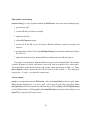
WD-pic,
a New Paradigm for Picture Drawing Programs
and
its Development as a Case Study of
the Use of its User’s Manual as its Specification
by
Lihua (Lizzy) Ou
A thesis
presented to the University of Waterloo
in fulfillment of the
thesis requirement for the degree of
Master of Mathematics
in
Computer Science
Waterloo, Ontario, Canada, 2002
c
°Lihua
Ou, 2002
I hereby declare that I am the sole author of this thesis.
I authorize the University of Waterloo to lend this thesis to other institutions or individuals for
the purpose of scholarly research.
I authorize the University of Waterloo to reproduce this thesis by photocopying or other means,
in total or in part, at the request of other institutions or individuals for the purpose of scholarly
research.
ii
The University of Waterloo requires the signatures of all persons using or photocopying this
thesis. Please sign below, and give address and date.
iii
Acknowledgements
Thanks are given to many people for their help on this thesis. First of all, I would like to thank my
supervisor Dr. Daniel M. Berry, who made the whole thesis possible and gave me many excellent
suggestions. I would also like to thank my readers Dr. Joanne M. Atlee and Dr. Michael W.
Godfrey for their great help on modifying the thesis. Jo also gave me plenty of encouragement
and support to do the first presentation of the work at an early stage. Michael lent me his PC
for the testing at the last stage. Thanks to Dr. Andrew J. Malton for his valuable suggestions.
Thanks to Steve and Shelly Rose for proofreading the manual. Last, but not the least, thanks
to my family and friends, including my boy friend, without whom this thesis would have been
much harder to write. Thank you.
iv
Abstract
The pic language is a graphics language for specifying line drawings to be typeset. The pic program is a pre-processor of troff that runs in batch mode on Unix environments. In this work, WDpic, a WYSIWYG Direct-manipulation pic, is developed. WD-pic operates on a new paradigm
for WYSIWYG, direct-manipulation picture drawing in which mouse movement is minimized
by use of natural defaults being used for information normally provided by the mouse, and in
which the internal representation is directly editable in the program. The work is also a case
study of using the user’s manual for a Computer-Based System (CBS) as its requirement specification. The result of the case study indicates that along several dimensions, user’s manual makes
an excellent requirement specification for CBSs. The user’s manual not only specifies the what
not how of the CBS at the users level, but it also serves as a useful requirements elicitation and
validation tool, as a repository of use cases, and as a useful source of covering test cases.
v
Contents
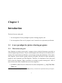
1 Introduction
1.1 A new paradigm for picture drawing programs . . . . . . . . . . .
1.1.1 Motivation and goals . . . . . . . . . . . . . . . . . . . .
1.1.2 Basic design idea . . . . . . . . . . . . . . . . . . . . . .
1.1.3 Related work . . . . . . . . . . . . . . . . . . . . . . . .
1.2 Case study of using a user’s manual as a requirements specification
1.2.1 Motivation and goals . . . . . . . . . . . . . . . . . . . .
1.2.2 Related work . . . . . . . . . . . . . . . . . . . . . . . .
1.3 Conventions . . . . . . . . . . . . . . . . . . . . . . . . . . . . .
1.3.1 Notational conventions . . . . . . . . . . . . . . . . . . .
1.3.2 Terms . . . . . . . . . . . . . . . . . . . . . . . . . . . .
1.3.3 Abbreviations . . . . . . . . . . . . . . . . . . . . . . . .
1.3.4 Organization of this document . . . . . . . . . . . . . . .
2 Picture Drawing
2.1 Basic paradigm and requirements .
2.2 User interface . . . . . . . . . . .
2.2.1 Screen layout . . . . . . .
2.2.2 Menu bar . . . . . . . . .
2.2.3 Pop-up menu . . . . . . .
2.2.4 Tool bar . . . . . . . . . .
2.2.5 Palette . . . . . . . . . . .
2.2.6 Canvas . . . . . . . . . .
.
.
.
.
.
.
.
.
.
.
.
.
.
.
.
.
vi
.
.
.
.
.
.
.
.
.
.
.
.
.
.
.
.
.
.
.
.
.
.
.
.
.
.
.
.
.
.
.
.
.
.
.
.
.
.
.
.
.
.
.
.
.
.
.
.
.
.
.
.
.
.
.
.
.
.
.
.
.
.
.
.
.
.
.
.
.
.
.
.
.
.
.
.
.
.
.
.
.
.
.
.
.
.
.
.
.
.
.
.
.
.
.
.
.
.
.
.
.
.
.
.
.
.
.
.
.
.
.
.
.
.
.
.
.
.
.
.
.
.
.
.
.
.
.
.
.
.
.
.
.
.
.
.
.
.
.
.
.
.
.
.
.
.
.
.
.
.
.
.
.
.
.
.
.
.
.
.
.
.
.
.
.
.
.
.
.
.
.
.
.
.
.
.
.
.
.
.
.
.
.
.
.
.
.
.
.
.
.
.
.
.
.
.
.
.
.
.
.
.
.
.
.
.
.
.
.
.
.
.
.
.
.
.
.
.
.
.
.
.
.
.
.
.
.
.
.
.
.
.
.
.
.
.
.
.
.
.
.
.
.
.
.
.
.
.
.
.
.
.
.
.
.
.
.
.
.
.
.
.
.
.
.
.
.
.
.
.
.
.
1
1
1
4
5
9
9
9
12
12
13
16
16
.
.
.
.
.
.
.
.
17
17
18
18
20
21
22
22
22
2.3
2.4
2.5
2.2.7 Edit window . . . . . . . . . . . . . . . . . . . . . . . . . . . . . . . . 23
2.2.8 Status bar . . . . . . . . . . . . . . . . . . . . . . . . . . . . . . . . . . 23
High level design (modules) . . . . . . . . . . . . . . . . . . . . . . . . . . . . 23
2.3.1 User Interface . . . . . . . . . . . . . . . . . . . . . . . . . . . . . . . . 25
2.3.2 File . . . . . . . . . . . . . . . . . . . . . . . . . . . . . . . . . . . . . 25
2.3.3 ExternalEditor . . . . . . . . . . . . . . . . . . . . . . . . . . . . . . . 25
2.3.4 EditWindow . . . . . . . . . . . . . . . . . . . . . . . . . . . . . . . . 26
2.3.5 Canvas . . . . . . . . . . . . . . . . . . . . . . . . . . . . . . . . . . . 27
2.3.6 PICObject . . . . . . . . . . . . . . . . . . . . . . . . . . . . . . . . . . 27
2.3.7 PICCompiler . . . . . . . . . . . . . . . . . . . . . . . . . . . . . . . . 28
2.3.8 Grid . . . . . . . . . . . . . . . . . . . . . . . . . . . . . . . . . . . . . 29
2.3.9 Gravity . . . . . . . . . . . . . . . . . . . . . . . . . . . . . . . . . . . 30
2.3.10 History . . . . . . . . . . . . . . . . . . . . . . . . . . . . . . . . . . . 30
2.3.11 Font . . . . . . . . . . . . . . . . . . . . . . . . . . . . . . . . . . . . . 31
2.3.12 Help . . . . . . . . . . . . . . . . . . . . . . . . . . . . . . . . . . . . . 31
Implementation . . . . . . . . . . . . . . . . . . . . . . . . . . . . . . . . . . . 31
2.4.1 pic code reuse . . . . . . . . . . . . . . . . . . . . . . . . . . . . . . . . 31
2.4.2 Data structures and algorithms . . . . . . . . . . . . . . . . . . . . . . . 34
2.4.3 Miscellaneous implementation details . . . . . . . . . . . . . . . . . . . 40
Evaluation . . . . . . . . . . . . . . . . . . . . . . . . . . . . . . . . . . . . . . 43
2.5.1 Evaluation of WD-pic relative to the pros and cons of batch and WYSIWYG 44
2.5.2 Future work . . . . . . . . . . . . . . . . . . . . . . . . . . . . . . . . . 44
3 Case study
3.1 Project plan . . . . . . . . . . . . . .
3.2 Results and introspection . . . . . . .
3.2.1 Requirements . . . . . . . . .
3.2.2 Design . . . . . . . . . . . .
3.2.3 Implementation . . . . . . . .
3.2.4 Testing . . . . . . . . . . . .
3.3 Author’s feelings during the life cycle
vii
.
.
.
.
.
.
.
.
.
.
.
.
.
.
.
.
.
.
.
.
.
.
.
.
.
.
.
.
.
.
.
.
.
.
.
.
.
.
.
.
.
.
.
.
.
.
.
.
.
.
.
.
.
.
.
.
.
.
.
.
.
.
.
.
.
.
.
.
.
.
.
.
.
.
.
.
.
.
.
.
.
.
.
.
.
.
.
.
.
.
.
.
.
.
.
.
.
.
.
.
.
.
.
.
.
.
.
.
.
.
.
.
.
.
.
.
.
.
.
.
.
.
.
.
.
.
.
.
.
.
.
.
.
.
.
.
.
.
.
.
.
.
.
.
.
.
.
.
.
.
.
.
.
.
.
.
.
.
.
.
.
46
46
48
50
52
52
53
53
4 Conclusions
55
A pic source code of figures in the thesis
A.1 Figure 1.1 . . . . . . . . . . . . .
A.2 Figure 1.2 . . . . . . . . . . . . .
A.3 Figure 1.4 . . . . . . . . . . . . .
A.4 Figure 2.3 . . . . . . . . . . . . .
A.5 Figure 2.4 . . . . . . . . . . . . .
A.6 Figure 2.5 . . . . . . . . . . . . .
A.7 Figure 2.6 . . . . . . . . . . . . .
A.8 Figure 2.7 . . . . . . . . . . . . .
A.9 Figure 2.11 . . . . . . . . . . . .
A.10 Figure 3.1 . . . . . . . . . . . . .
A.11 Figure 3.2 . . . . . . . . . . . . .
.
.
.
.
.
.
.
.
.
.
.
57
57
58
58
59
60
61
61
62
63
64
65
.
.
.
.
.
66
66
66
66
66
66
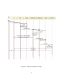
B Sequence diagrams
B.1 Opening a file . . . . . . .
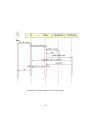
B.2 Inserting an object . . . . .
B.3 Selecting an object . . . .
B.4 Defining & activating grid
B.5 Setting font and size of text
.
.
.
.
.
.
.
.
.
.
.
.
.
.
.
.
.
.
.
.
.
.
.
.
.
.
.
.
.
.
.
.
.
.
.
.
.
.
.
.
.
.
.
.
.
.
.
.
.
.
.
.
.
.
.
.
.
.
.
.
.
.
.
.
.
.
.
.
C WD-pic user’s manual
.
.
.
.
.
.
.
.
.
.
.
.
.
.
.
.
.
.
.
.
.
.
.
.
.
.
.
.
.
.
.
.
.
.
.
.
.
.
.
.
.
.
.
.
.
.
.
.
.
.
.
.
.
.
.
.
.
.
.
.
.
.
.
.
.
.
.
.
.
.
.
.
.
.
.
.
.
.
.
.
.
.
.
.
.
.
.
.
.
.
.
.
.
.
.
.
.
.
.
.
.
.
.
.
.
.
.
.
.
.
.
.
.
.
.
.
.
.
.
.
.
.
.
.
.
.
.
.
.
.
.
.
.
.
.
.
.
.
.
.
.
.
.
.
.
.
.
.
.
.
.
.
.
.
.
.
.
.
.
.
.
.
.
.
.
.
.
.
.
.
.
.
.
.
.
.
.
.
.
.
.
.
.
.
.
.
.
.
.
.
.
.
.
.
.
.
.
.
.
.
.
.
.
.
.
.
.
.
.
.
.
.
.
.
.
.
.
.
.
.
.
.
.
.
.
.
.
.
.
.
.
.
.
.
.
.
.
.
.
.
.
.
.
.
.
.
.
.
.
.
.
.
.
.
.
.
.
.
.
.
.
.
.
.
.
.
.
.
.
.
.
.
.
.
.
.
.
.
.
.
.
.
.
.
.
.
.
.
.
.
.
.
.
.
.
.
.
.
.
.
.
.
.
.
.
.
.
.
.
.
.
.
.
.
.
.
.
.
.
.
.
.
.
.
.
.
.
.
.
.
.
.
.
.
.
.
72
viii
List of Figures
1.1
1.2
1.3
1.4
1.5
1.6
WD-pic usage . . . . . . .
Execution steps in WD-pic
A sample drawn by dot . .
A sample drawn by pic . .
dot code of Figure 1.3 . .
pic code of Figure 1.4 . . .
.
.
.
.
.
.
.
.
.
.
.
.
.
.
.
.
.
.
.
.
.
.
.
.
.
.
.
.
.
.
.
.
.
.
.
.
.
.
.
.
.
.
.
.
.
.
.
.
.
.
.
.
.
.
.
.
.
.
.
.
.
.
.
.
.
.
.
.
.
.
.
.
.
.
.
.
.
.
.
.
.
.
.
.
.
.
.
.
.
.
.
.
.
.
.
.
.
.
.
.
.
.
.
.
.
.
.
.
.
.
.
.
.
.
.
.
.
.
.
.
3
5
7
7
7
7
2.1
2.2
2.3
2.4
2.5
2.6
2.7
2.8
2.9
2.10
2.11
Screen layout of WD-pic . . . . . . . . . . .
Screen layout with box attribute buttons . . .
WD-pic system architecture . . . . . . . . .
PICObject class diagram . . . . . . . . . . .
Corners of an ellipse . . . . . . . . . . . . .
Compiling process . . . . . . . . . . . . . .
Euclidean coordinate & the screen coordinate
gravitate to . . . . . . . . . . . . . . . . . .
Adjust text position . . . . . . . . . . . . . .
A sample of font setting . . . . . . . . . . . .
Font related data structure . . . . . . . . . .
.
.
.
.
.
.
.
.
.
.
.
.
.
.
.
.
.
.
.
.
.
.
.
.
.
.
.
.
.
.
.
.
.
.
.
.
.
.
.
.
.
.
.
.
.
.
.
.
.
.
.
.
.
.
.
.
.
.
.
.
.
.
.
.
.
.
.
.
.
.
.
.
.
.
.
.
.
.
.
.
.
.
.
.
.
.
.
.
.
.
.
.
.
.
.
.
.
.
.
.
.
.
.
.
.
.
.
.
.
.
.
.
.
.
.
.
.
.
.
.
.
.
.
.
.
.
.
.
.
.
.
.
.
.
.
.
.
.
.
.
.
.
.
.
.
.
.
.
.
.
.
.
.
.
.
.
.
.
.
.
.
.
.
.
.
.
.
.
.
.
.
.
.
.
.
.
.
.
.
.
.
.
.
.
.
.
.
.
.
.
.
.
.
.
.
.
.
.
.
.
.
.
.
.
.
.
.
.
.
18
19
24
28
29
32
35
37
39
41
41
3.1
3.2
WD-pic project plan . . . . . . . . . . . . . . . . . . . . . . . . . . . . . . . . 47
WD-pic development process . . . . . . . . . . . . . . . . . . . . . . . . . . . . 49
.
.
.
.
.
.
.
.
.
.
.
.
.
.
.
.
.
.
.
.
.
.
.
.
.
.
.
.
.
.
.
.
.
.
.
.
.
.
.
.
.
.
.
.
.
.
.
.
.
.
.
.
.
.
B.1 Sequence diagram of file open . . . . . . . . . . . . . . . . . . . . . . . . . . . 67
B.2 Sequence diagram of inserting an object . . . . . . . . . . . . . . . . . . . . . . 68
ix
B.3 Sequence diagram of selecing an object . . . . . . . . . . . . . . . . . . . . . . 69
B.4 Sequence diagram of defining and activating grid . . . . . . . . . . . . . . . . . 70
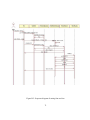
B.5 Sequence diagram of setting font and size . . . . . . . . . . . . . . . . . . . . . 71
x
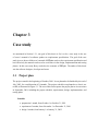
Chapter 1
Introduction
This thesis has two main goals:
1. the investigation of a new paradigm for picture drawing programs, and
2. the investigation of the use of a program’s user’s manual as its requirement specification.
1.1 A new paradigm for picture drawing programs
1.1.1 Motivation and goals
Line diagrams are widely used in today’s computer science technical documents, especially in
software engineering documents. They are used through out the whole process of software development, from requirements specification, system design, testing and maintenance. Flow charts,
state diagrams, system structure graphs, program call graphs, and object-to-object dependency
graphs are some commonly used line diagrams. Therefore, it is important to have some good
tools to draw the diagrams. Many researchers are working on picture drawing tools. Each of
most of these tools can be classified into one of two categories 1 :
• WYSIWYG (What You See Is What You Get) direct manipulation, e.g., xfig, Paint, MacDraw, and
1
This dichotomy is used by the customer of WD-pic, Berry, to motivate the requirements and to provide goals.
1
• batch, e.g., pic [9, 10, 18], dot [13].
Shpilberg discusses the advantages and disadvantages of these categories [17]. The advantages of WYSIWYG picture-drawing programs are as follows:
• The user can see the whole picture while composing.
• It is easier for the user to decide the objects’ shapes, sizes, positions, etc. Therefore, obvious errors can be avoided.
Most of the WYSIWYG picture-drawing programs have the following disadvantages:
• Changing one object in the picture might destroy the whole picture, because the layout of
each object in the picture is done manually by the user. For example, if the user changes the
size or position of one object, the size or position of the other objects which are connected
to the changed one have to be changed as well.
• It is not easy to manipulate the objects of a category as a group, e.g., changing all the boxes
in the picture to circles and changing the sizes of all the boxes in the picture.
Programs in batch mode, on the other hand, have advantages which are lacking in WYSIWYG mode programs. The advantages of batch mode programs are as follows:
• Inserting or deleting an object or changing its size or location does not destroy the entire
picture. The batch program recalculates the layout of the whole picture and redraws it
automatically.
• It is easy to manipulate objects of a category as a group. For example, if the user wants
to change all the boxes in the picture to circles. Since the description of whole picture is
stored in a plain text file, the user can search for each “box” in the picture and replace it
with a “circle”.
The disadvantages of the batch mode programs are as follows:
• The user cannot see the picture while composing its description.
• It is easier to make an error.
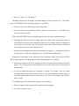
2
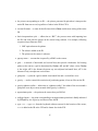
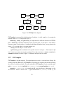
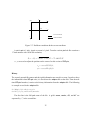
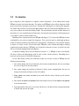
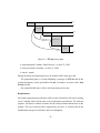
document
WD-pic
pic file
pic
troff
picture
picture
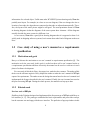
Figure 1.1: WD-pic usage
Our motivation is to develop a picture drawing program that gets the best of both batch and
WYSIWYG modes.
The pic program is a troff [11] preprocessor. It is ideally suited for drawing diagrams in
computer science documents. The internal representation of a picture in pic language is easily
understood by a human. Based on these facts, we built WD-pic on top of the pic program. Our
goal is to keep the pic program’s batch defaults and additionally, make it possible for users to
compose pictures through a graphic user interface, i.e., by mouse clicking or by typing from the
keyboard. For example, to draw a picture with a circle in it, the user can use any text editor to
compose a pic file with “circle" in it, as with the batch pic program. Alternatively, in WD-pic,
the user can either type “circle” from the keyboard, or simply click the circle button on the
palette. Either way, a circle is drawn on WD-pic’s canvas. What the user sees on the canvas is
what the user gets.
WD-pic can be run as an independent program on a Unix Solaris or a Windows 95/98/2000
environment, or as a preprocessor of the pic program. It draws pictures on its built-in canvas.
Its internal representation can be made into a pic file, and then passed to the pic program, which
outputs to troff, as illustrated in Figure 1.1. What is printed finally is what was shown on the
canvas in WD-pic.
The reader should be aware that all the line-drawing figures in this thesis were produced by
the author using WD-pic. The produced pic file was then processed, as suggested in Figure 1.1,
by pic and troff to produce a P OST S CRIPT file that is included into the LATEX source for this
thesis.
3
1.1.2 Basic design idea
Like other WYSIWYG picture drawing programs, WD-pic has a Graphic User Interface (GUI),
which provides menus, palette, canvas, and a built-in text editor to users for directly manipulating
pictures or textually composing and editing picture descriptions. The canvas provides a graphical
view of the picture, while a textual view of the picture is shown in the editor window. The basic
design ideas are as follows:
1. WD-pic is made up of a GUI and a pic interpreter built from the pic program, which is
effectively a pic compiler, thus obtaining pic code reuse. They are connected by a bridge.
2. The GUI consists of standard components, e.g., menu bar, tool bar, and a palette which
contains all the pic primitive tokens, a canvas for graphical view of the picture and direct
manipulations, and a text editor window (EW) for a textual view of the internal representation (IR) of the picture.
3. All the mouse clicking and keyboard typing events from the GUI are classified into two
categories:
• affecting the IR, and
• affecting the session.
4. After an event of the former kind, the current complete IR is sent to the pic interpreter.
5. The pic interpreter builds from the IR a data structure describing each picture element and
its size, location, and other attributes.
6. The GUI gets the picture information from the data structures and draws the entire picture
on the canvas.
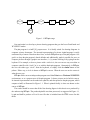
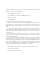
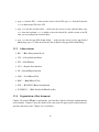
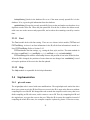
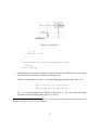
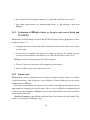
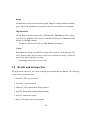
Figure 1.2 illustrates the process of how WD-pic works.
Some other design goals of the user interface of WD-pic are the following:
• All styles of input, i.e., by mouse or by keyboard, are fully interchangeable, without the
need to inform the application from where its next input is coming.
4
WD-pic
keyboard
GUI
input
affecting IR
events
IR
pic
compiler
GUI
output
mouse
affecting session
events
Figure 1.2: Execution steps in WD-pic
• There is no need to move the mouse to the canvas or the EW except to explicitly and
directly identify a point or an object; therefore, the mouse movement is minimized.
• The internal representation should be as much as possible what a human would write in
the pic language to achieve the picture shown on the canvas.
• When inputting text that is expected and that has a definite end, there is no need to move
the mouse to a text window and to confirm at the end.
1.1.3 Related work
Most picture drawing programs come in either WYSIWYG mode or batch mode. Shpilberg
discussed a few of each in [17]. A famous diagram visualization system with both WYSIWYG
and textual views of the pictures is Graphviz [1, 2]. It was developed by AT&T research lab.
Graphviz is a set of graph drawing tools, including dot [13], neato [15], lefty [12], dotty [14],
etc., which are similar in construction to WD-pic.
dot & pic
Like pic, dot is a batch picture drawing program. It accepts input in the dot language and makes
hierarchical layouts of directed graphs. Undirected graphs are handled by neato, which shares
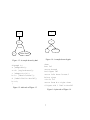
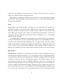
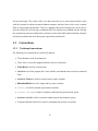
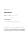
with dot the input file format and the graphics drivers. Figure 1.3 is a simple graph generated
5
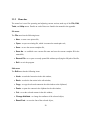
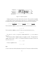
from the dot code in Figure 1.5. It has four nodes connected by three edges. Figure 1.4 is a graph
generated from the pic code in Figure 1.6, showing the same layout.
We can see the main differences between dot and pic from the above sample. In dot, the
user specifies the nodes and their attributes including shape; label, which by default is the node’s
name; and the edges and their attributes including the source and the target nodes. The sizes
and positions of nodes and edges are calculated automatically. The picture drawing orientation
by default is from top to bottom. In pic, nodes and edges are equally treated as objects. The
user has to specify the length and path of the line object that connects two node objects. The
drawing orientation by default is from left to right. Therefore, dot is more powerful in drawing
complex graphs, i.e., graphs with lots of nodes. However, it draws directed, acyclic graphs only
hierarchically. pic is more suitable for drawing simple directed or undirected graphs.
There are some other advantages of dot. It has color and font attributes and outputs in common graphics languages, e.g., ps, gif, and png, while pic, being a troff pre-processor, does not
have these features.
lefty
lefty [8, 12] is a two-view graphics editor: WYSIWYG view and textual view. The user can edit
the picture from any of the views. From the WYSIWYG view, a node can be added or relocated
by mouse movement. An equivalent result can be obtained by entering expressions in the editor’s
language in the textual view.
A unique feature of lefty is its use of a single language to describe all aspects of picture handling. Picture descriptions consist of two parts: data structure that hold information about the
picture, e.g., objects in the picture and their locations and sizes, and functions that implement operations on the data structure, e.g., functions to insert, delete, move, draw objects. The language
was inspired by the language in the EZ system [8]. It is similar to AWK and C, not as easy to
read as the pic language.
Another prominent feature of lefty is its programmability, i.e., a user can program and customize lefty to the way he or she likes by using its programming language. For example, by
default, a left mouse click on the canvas inserts a new node. The user can change the program
to insert a new node by a middle mouse click. However, with only a simple split window for
WYSIWYG view and text view and a long pop-up menu, which is invoked by a right mouse
6
a
a
..
.
.
.
..
.
.
.
.
b
b
event
event
c
c
Hello World
Hello World
Figure 1.3: A sample drawn by dot
digraph G {
a [shape=box];
a –> b [style=dotted];
c [shape=circle];
b –> c [label="event"];
d [label="Hello World"];
b –> d;
}
Figure 1.4: A sample drawn by pic
down
box "a"
arrow dotted
B:ellipse "b"
arrow left down "event"
below rjust
circle "c"
arrow from B.s right down
ellipse wid 1 "Hello World"
Figure 1.5: dot code of Figure 1.3
Figure 1.6: pic code of Figure 1.4
7
click on the canvas, lefty is not convenient to use. It does not have a menu bar, a tool bar, a
palette etc. as most GUI picture drawing tools have.
lefty’s ability to communicate with other processes allows it to use existing tools to compute
specific picture layouts and allows external processes to use it as a front end to display pictures’
data structures graphically.
dotty
dotty is built on top of dot and lefty. Like lefty, it can be customized and controlled by a
WYSIWYG interface and a textual interface. dotty loads the picture file in the dot language.
lefty starts up dot as a separate process to compute layouts. When the user asks for a new
layout, lefty sends the graph to dot. dot has very good auto-layout algorithms. So it does the
computation, and sends the new layout information, such as coordinates, sizes, etc., back to lefty.
lefty then redraws the graph.
As with lefty, dotty is intended to be programmed to act as a front end for other applications.
It can run also stand alone. However, because dotty is built on top of dot and lefty, its features
are limited to the features that dot and lefty provide. The same as lefty, it has only a simple
window as the canvas and a pop-up menu which can be invoked by a right mouse click on the
canvas. This GUI is not as user friendly as WD-pic’s. However, dotty uses dot to do layout. So
dotty is more suitable for drawing a complex picture with lots of nodes or to be used a font end.
Rational Rose
Rational Rose is UML-based, model-driven tool, which can generate diagrams for objectoriented analysis, modeling and design [3, 4]. Laying aside its analysis and designing function,
we only discuss its function to draw diagrams here. Rose has a standard GUI which contains
a menu bar, a tool bar, a browser, a documentation window , and a diagram window. The diagram window is actually the canvas as in WD-pic. Rose has a limited set of elements for the
purpose of design and analysis, the user can generate only class, use-case, state machine, interaction, component and deployment diagrams. Working with these diagrams, the user can do
move, resize, copy, paste, cut, etc. direct manipulations in the diagram window. Rose does not
have a textual view of the diagram. The documentation window is only for showing and editing
8
information of a selected object. Unlike most other WYSIWYG picture drawing tools, Rose has
partially auto-layout. For example, in a class or use case diagram, if the user changes the size or
location of one node, the edges that are connected to that node are adjusted automatically. Therefore, the layout of the entire picture might be still good. The most prominent feature of Rose
in drawing diagrams is that the diagrams of the same system share elements. All the diagrams
actually describe the same system in a different view.
As we can see, Rose does a good job in drawing diagrams that it is supposed to draw. It is
widely used in designing software systems, but it cannot draw other kind of diagrams as the user
likes.
1.2 Case study of using a user’s manual as a requirements
specification
1.2.1 Motivation and goals
Berry et al discuss the motivation to use user’s manual as requirements specification [6]. The
motivation to do the case study in this work is to find out how well a user’s manual works as
a requirements specification and how effectively the manual can be used as a reference in each
phase of software development.
For case study of this thesis, Berry, the supervisor, worked as the customer. The author of this
thesis was the software engineer. Berry helped the author to make the user’s manual of WD-pic
capture his requirements. The author wrote the design document based on the user’s manual and
implemented the features described in the user’s manual. Finally, the user’s manual was used as
the plan for testing WD-pic. During the whole process, the manual was kept up to date.
1.2.2 Related work
Previous work of WD-pic
Shpilberg in the Technion designed and implemented the first prototype of WD-pic with Berry as
her customer [6, 17]. The prototype established the basic requirements and proved the concept,
but the customer was not happy with the user interface. The profusion of pop-up windows in this
9
prototype was inundate. For example, if the user wants to draw a box with a specified size and
location. The user has to do the following steps:
1. Click the box button on the palette.
2. Click the size button on the palette. The Size dialog shows up.
3. Input the size of the box.
4. Click the OK button.
Then the user has to do the similar steps to change the location of the box.
This causes lots of mouse movement, and the click of the OK button to confirm the correctness of inputting text is actually not necessary. It would be much nicer if the user can just click
the box button and type from the keyboard the size and location of the box without moving the
mouse.
The UI problem in Shpilberg’s prototype is not fixable because she used standard widgets.
These widgets require bringing up an interaction window when it is desired to input from the key
board and these windows require confirmation of the input. To fix this problem actually means
rewrite all the code.
Still later, four students, Daudjee, Dong, A. and T. Nelson, at the University of Waterloo
wrote improvements of the user’s manuals for WD-pic. Because of time limits, they did not
implement the specified systems.
The documents of the previous work of WD-pic were given to the author at the beginning
of the project for her to get familiar with the project. She laid these documents aside when she
started to design the program. Shpilberg’s prototype was developed in X-windows environment
using C. In the new WD-pic, the idea of re-use of the pic compiler is the same. But the author
did not reuse any of Shpilberg’s code. The new WD-pic was coded in Java from scratch. Major
improvements and new features added in the new WD-pic are as the follows:
• Mouse movements are minimized. Pop-up windows are used only when necessary.
• A built-in text editor is added.
• It is able to report all the syntax errors.
10
• More direct manipulations are added. The user can now specify an object to be drawn
anywhere on the canvas by a mouse-click at the desired point.
• The use can preview font settings.
• Recently opened file history is added.
• Grid is added. The user can define as many grids as he or she like. Gravity supports three
levels.
• The user can see current values of the pic variables as well as change these values.
• A tool bar and a status bar are added.
• Preference setting is added.
• The program can run on Windows as well as Unix environments.
As we can see the GUI of the new WD-pic is much more user-friendly. The customer is very
happy with the product.
Development of flo
Wolfman designed and developed the program flo by using user’s manual as the requirements
document [6]. flo is a pic preprocessor. It translates a flowchart specification that is embedded
inside a file containing ditroff input into a pic specification. In this project, Wolfman was the software engineer. Berry was the customer. The project was research in electronic publishing. They
started from writing the user’s manual because of the batch nature of the program. Later, they
realized that this user’s manual became the requirement specification and the whole development
was centered on the production of the user’s manual.
Industrial case study
Finestein did a case study of using user’s manual as a requirements specification in the development of ExpressPath [6, 7]. ExpressPath is a natural language speech recognition system
developed by LGS, an IBM company. Finestein participated in the entire requirements analysis
11
and system design. The results of the case study show that it was easier than normal to work
with the customer to address potential human-computer interface issues with a user’s manual
form of requirements specification. The user’s manual reduced the learning curve of new developers by at least 50% over having a traditional SRS. The customer was satisfied with the fact that
the requirements processes allowed the customer to detect and readily address human-computer
interaction problems that arose during the requirement specification.
1.3 Conventions
1.3.1 Notational conventions
The following text conventions are used in the manual:
• Times Roman is used for normal text.
• Times Italics is used for emphasis and new terms in normal text.
• Times Bold is used for section names.
• Helvetica is used for program, file, class, module, and method names except in command
lines.
• Helvetica Oblique is used for widget and key name variables.
• Helvetica Bold is used for widget and key name constants.
• Courier is used for internal representation contents.
• Courier Oblique is used for variables of pic internal representation syntax.
• Courier Bold is used for constants of pic internal representation syntax.
• Computer Modern Sans Serif is used for command code and use case names.
12
1.3.2 Terms
The following terms are used throughout the manual:
• WD-pic — the name of the program.
• user — the person who uses WD-pic, addressed by “you”.
• pic primitive — abbreviate as “primitive”, defined by the pic grammar, e.g., box, line,
arrow, circle, ellipse, arc, spline, and move.
• pic object — abbreviate as “object”, a pic primitive together with its attributes.
• pic token — abbreviate as “token”, a smallest semantically meaningful syntactic unit in
the pic language, e.g., box, line, arrow, circle, ellipse, arc, spline, move,
up, down, left, right, ;, :, ", and variable identifiers.
• attribute — used to give more information about a primitive, consisting of a keyword,
perhaps followed by a value, e.g.,
h(eigh)t expr,
rad(ius) expr,
up opt-expr,
right opt-expr,
from position,
at position,
by expr,
dotted opt-expr,
chop opt-expr,
invis,
fill opt-expr,
text-list,
wid(th) expr,
diam(eter) expr,
down opt-expr,
left opt-expr,
to position,
with corner,
then,
dashed opt-expr,
-> <- <->,
solid,
same,
expr.
In these attributes, the parenthesized text describes an optional full spelling of the containing token.
13
• internal representation — abbreviate as “IR”, the text file containing the pic code corresponding to the picture drawn on the canvas.
• session — an invocation of WD-pic.
• edit window — abbreviate as “EW”, the window used to view and edit the IR.
• external editor — your preferred text editor, not part of WD-pic, indicated to your operating system by setting a shell variable, e.g., setenv EDITOR vi.
• canvas — used for displaying the picture corresponding to the IR.
• palette — used for causing input to the IR, made up of the box, circle, ellipse, line,
arrow, spline, arc, ;, ", Constructs, Copy, Macros, Label, and Variables buttons,
and an attribute area, whose content changes to provide the attributes for the object that
was most recently inserted.
• menu bar — used for operating and adjusting current session, made up of the File, Edit,
Tools, and Help menus.
• menu item — a unit of a menu.
• tool bar — shortcuts to some menu items, made up of the New, Open, Save, Copy,
Paste, Undo, Redo, Grid, and Help buttons.
• screen layout — made up of a menu bar, a tool bar, a palette, a canvas and an EW, as shown
in Figure 2.1.
• left mouse click — abbreviate as “LMC”, a left mouse click.
• right mouse click — abbreviate as “RMC”, a right mouse click.
• double click — two LMCs not more than 1 second apart.
• current insertion point — abbreviate as “CIP”, the point in the IR in which the next object
will be inserted, indicated by the cursor on the canvas and the cursor in the EW; normally,
it is after the last inserted object.
14
• the picture corresponding to an IR — the picture generated by pic when it interprets the
entire IR from start to end, regardless of where in the IR the CIP is.
• current file name — a name for the file into which a Save would cause writing of the entire
IR.
• basic interpretation cycle — abbreviate as “BIC”, the process starts with inputting into
the IR, and ends with the picture on the canvas being redrawn. For example, following
sequenced steps illustrate a BIC:
1. LMC a pic token on the palette.
2. The token is added to the IR.
3. The picture on the canvas is redrawn.
• pop-up menu — a menu that is opened by a RMC on the canvas.
• grid — a network of horizontal and vertical lines that provide coordinates for locating
points on the canvas; a grid is determined by Center , dX , and dY values, where Center
is the origin; dX is the distance between any two adjacent horizontal lines; dY is the
distance of any two adjacent vertical lines.
• grid point — a point in a grid at which a horizontal line and a vertical line cross.
• gravity — used to control the restriction of positioning points; it has no effect on the IR.
• gravity tightness radius — abbreviate as “tightness radius”, the radius of the area around a
grid point or an object corner around which gravity is effective.
• approximate point — the point on the canvas that you LMCed.
• indicated point — the point corresponding to an approximate point that is finally indicated
by WD-pic by use of gravity and inserted into the IR.
• type xxx — type xxx from the keyboard without concern for the location of the cursor;
xxx is added to the IR at the CIP and is shown also in the EW.
15
• type xxx into the EW — make sure the cursor is in the EW; type xxx from the keyboard;
xxx is added to the EW at the CIP.
• type xxx into the external editor — make sure the cursor is in the external editor, type
xxx from the keyboard; xxx is added to the to-be-edited file, which is taken as the IR
after you save and quit the external editor.
• type xxx into the yyy field of zzz dialog — make sure the cursor is in the yyy field of
zzz dialog; type xxx from the keyboard; xxx is added to the yyy field of zzz dialog.
1.3.3 Abbreviations
• BIC — Basic Interpretation Cycle
• CIP — Current Insertion Point
• EW — Edit Window
• GUI — Graphic User Interface
• IR — Internal Representation
• LMC — Left Mouse Click
• RMC — Right Mouse Click
• WD — WYSIWYG Direct-manipulation
• WYSIWYG — What You See Is What You Get
1.3.4 Organization of this document
Chapter 2 describes WD-pic’s requirements, user interface, high-level design, implementation,
and evaluation. Chapter 3 gives the details of the case study, the project plan, results and introspection, and future work. Chapter 4 is a conclusion.
16
Chapter 2
Picture Drawing
2.1 Basic paradigm and requirements
Compared to other picture drawing programs, the major advantage of WD-pic is its GUI. Not
only does this GUI provide both WYSIWYG and textual views of the picture to users, but also it
provides grid and gravity, external and internal text editors, syntax checking, etc. The novel UI
requirements of WD-pic are that:
• All styles of input, i.e., by mouse or by keyboard, are fully interchangeable, without the
need to inform the application from where its next input is coming.
• There is no need to move the mouse to the canvas or the EW except to explicitly and
directly identify a point or an object; therefore, mouse movement is minimized.
• When inputting text that is expected and that has an algorithmically detectable end, there
is no need to move the mouse to a text window to input the text and to confirm at the end.
• The internal representation should be as much as possible what a human would write in
the pic language to achieve the picture shown on the canvas.
The first three are achieved by virtue of the fact that the user is viewed as inputting internal
representation rather than building a picture per se. This view permits the grammar of the internal
representation to guide the program’s acceptance of the user’s input.
17
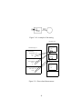
Figure 2.1: Screen layout of WD-pic
2.2 User interface
2.2.1 Screen layout
WD-pic starts up with the screen layout illustrated in Figure 2.1.
The main window is made up of six main parts:
• the menu bar
• the tool bar
• the palette
18
Figure 2.2: Screen layout with box attribute buttons
• the canvas
• the edit window (EW)
• the status bar
The red star on the canvas represents the current insertion point (CIP).
The attribute area is empty in the start up screen layout. It is filled with attribute token buttons
when the CIP is at some object. These attribute buttons change according to the object where the
CIP is at. Figure 2.2 illustrates the screen layout when the CIP is just after box.
19
2.2.2 Menu bar
The menu bar is used for operating and adjusting current session, made up of the File, Edit,
Tools, and Help menus. Details on each of these are found in the manual in the appendix.
File menu
The File menu has the following items:
• New - to start a new picture file,
• Open - to open an existing file, which is assumed to contain pic code,
• Save - to save the current complete file,
• Save As - to establish a new current file name and save the current complete IR in the
named file,
• Recent File - to re-open a recently opened file without specifying the full path of the file,
• Exit - to exit the program.
Edit menu
The Edit menu has the following items:
• Undo - to undo the last action in the edit window,
• Redo - to redo the last action in the edit window,
• Copy - to copy the selected content in the edit window to the clipboard,
• Paste - to paste the content in the clipboard to the edit window,
• Cut - to cut the selected content in the edit window,
• Change Attribute - to change the attributes of the selected object,
• Reset Font - to reset the font of the selected object,
20
• Set CIP - to set CIP after the selected object,
• Run External Editor - to run the external editor.
Undo and Redo are not always available. Undo is enabled only when there has been some
change made to the IR, e.g., adding, deleting text. The user can widUndo to the beginning of the
session. Redo is enabled when Undo has been done.
Tools menu
The Tools menu has the following items:
• Font - to change the font of the selected text on the canvas,
• Set External Editor - to set the external editor to an accessible text editor on the user’s
system,
• Define Grid - to define a new grid or modify an existing grid,
• Activate Grid - to activate a previously saved grid,
• Set Gravity - to set the gravity values,
• Preferences - to set the preferences of pic objects.
Help menu
The Help menu brings up the help information of WD-pic. It has Contents and About items.
2.2.3 Pop-up menu
The pop-up menu is made up of the Set CIP, Change Attribute, Reset Font, Activate Grid
and Set Gravity items. These menu items are shortcuts to the same items in the menu bar.
21
2.2.4 Tool bar
The tool bar is made up of the New, Open, Save, Copy, Paste, Cut, Undo, Redo, Grid
Activate and Help buttons. These buttons are shortcuts to the related menu items. Tips are
provided for users who are not sure about the usages of buttons. By moving the mouse over a
button, a small tip of what the button is for shows up.
The tool bar can be dragged out of the current position and floated horizontally or vertically
in the main window.
2.2.5 Palette
The palette is used for causing input to the IR. The box, circle, ellipse, line, arrow, spline,
arc, ;, ", Constructs, Copy, Macros, Label, and Variables buttons are always available in
the palette. If the name of a button begins with a lower-case letter, e.g., box and circle, it is a pic
token. LMCing this button inserts the token into the IR at the CIP. LMCing a button beginning
with an upper case letter, e.g., Constructs and Macros, invokes a dialog for inputting the parts
of the pic statements not beginning with pic primitives, such as conditionals, loops, and macros.
The attribute buttons are available when the CIP is at some object. As shown in Figure 2.2,
there are three kinds of attribute buttons in the attribute area:
• an independent button, e.g., fill and invis. LMCing one of these buttons will add its token,
e.g., fill and invis, to the IR at the CIP.
• a button with a value field, e.g., wid and ht. After filling in the corresponding value field,
LMCing one of these buttons causes the addition of both the selected token and the value
shown in its value field to the IR.
• a button in a set of buttons connected with ks, e.g., solid k dashed k dotted. LMCing
one of them to add its token to the IR. At most one of these buttons can be selected.
2.2.6 Canvas
The canvas is used for displaying the picture corresponding to the complete current IR and directly manipulating objects, such as selecting an object and indicating a point. The CIP is always
22
shown on the canvas. It helps the user to track the location of the CIP in the IR.
The objects are painted in two colors on the canvas: black and light purple (RGB 204x204x255).
Black is for normal objects. Light purple is for selected objects. In order that the user easily locate the selected objects on the canvas and in the edit window, the same selection color is used
in the edit window.
The divider between the canvas and the edit window is adjustable. It can be moved up and
down to adjust the sizes of the canvas and the edit window.
2.2.7 Edit window
The edit window (EW) is implemented as a text editor, with which the user can view and edit
the IR, copy, paste, cut, undo, redo like a normal text editor. It also helps the user to do syntax
checking. The text in EW is shown in three colors: black, light purple, and red. Normal text is
in black. Selected text is in light purple. Text with a syntax error is in red.
2.2.8 Status bar
The status bar is used for displaying error information and the coordinates of the point, if any,
on the canvas at which the mouse is pointed. If a user runs some session command and does not
see any change on the canvas, there might be some error message shown in the status bar. For
example, if a user activates a grid, but the grid is not drawn on the canvas, there might be some
information in the status bar telling the user what is wrong.
The coordinates of the mouse’s position on the canvas might be displayed as a grid point or
as an object’s corner, if it is available. Otherwise, it is shown in a pair of real numbers, the (x, y)
coordinates of the mouse’s position.
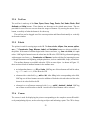
2.3 High level design (modules)
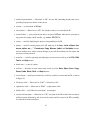
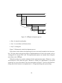
Figure 2.3 illustrates the system architecture of WD-pic. It is made up of the following modules:
UI, File, ExternalEditor, EditWindow, Canvas, PICObject, PICCompiler, Grid, Gravity,
History, Font, and Help.
23
External Editor
Help
File
UI
.. . . . . . . . . . . . . . . . . . . . . . . . . . . . . . . . . . . . ..
.
.
.
.
.
.
Legend
..
..
.
.
.
.
.
.
..
navigate ..
.
.
.
.
.
.
..
..
.
reference ..
.
.
.
.....................................
Gravity
Grid
EditWindow
Canvas
Font
PICCompiler
PICObject
History
Figure 2.3: WD-pic system architecture
24
2.3.1 User Interface
The UI module is responsible for the user interface of WD-pic, including the screen layout mentioned in Section 2.2 and all the dialogs that the user sees. It consists of the WDPic class, the
AttrPane package, and the MyDialog package. WDPic implements the main frame of WD-pic.
AttrPane contains the attribute pane for each pic primitive. MyDialog contains all the dialogs.
Each element, e.g., a menu item and a button, on the user interface is assigned an action
command. If two elements implement the same function, they are assigned the same action command. WDPic itself implements ActionListener, which is a standard class in Java. Therefore,
when WDPic hears an action, it checks the action command and calls the related method. Thus,
it does not need to care whether the action is from a menu item or a tool button. For example,
both the New item in the File menu and the New button in the tool bar create a new file. They
are assigned the same action file.new. If a user selects New from the File menu, WDPic
gets the file.new action, the new() method of the File class is called. If the user LMCs the
New button in the tool bar, WD-pic also gets the file.new action and calls the new() method.
2.3.2 File
The File module handles all the actions that are invoked by the File menu, including creating
a new file, opening an existing file, saving current complete file, establishing a new current file
name, saving the current complete IR in the named file, and exiting the program. These actions
are done by doNew(), doOpen(), doSave(), doSaveAs(), and doExit().
doOpen() calls EditWindow to import the file as to-be-edited IR. It also looks up in the
history database file to see whether there are previously saved grids. If so, it retrieves the grid
information and activates the grid. It then updates and saves the history database file, records the
just opened file as the most recently opened file.
doSave() calls History to update and save the history database file.
For details of History, please refer to Section 2.4.2.
2.3.3 ExternalEditor
The ExternalEditor module handles actions of the external editor, including getting the name of
the system default editor, setting a specific editor that is accessible from the system to be the ex25
ternal editor, and running the specified external editor. These actions are done by getExtEditor(),
setExtEditor(editor), and runExtEditor().
Because the Runtime class in Java cannot run non-windowed application, e.g., pico and
vi, from a GUI program, a C program is written for the Unix version of WD-pic to run nonwindowed programs in a standard terminal window. For details, please refer to Section 2.4.3.
2.3.4 EditWindow
The EditWindow module handles actions of the IR, e.g., composing, importing and exporting
the IR, sending the IR to the pic compiler to compile, and actions of the built-in text editor,
including copy, paste, cut, undo, and redo, as well as checking syntax and setting the CIP.
The main methods of this class are importIR(file), exportIR(file), insertPrimitive(s),
insertModifier(s), isAtPosCtlPhrase(), isAtObjectPhrase(), setSelected(idx), setCIPAfterSelected(), and renewLooking().
importIR(file) is used for importing the file file as the IR to the edit window. exportIR(file) is used for exporting the IR to a file named file. These two methods are mainly
used by File when the user opens and saves a file.
insertPrimitive(s) is called when a user LMCs the pic primitive tokens, e.g., box, circle,
ellipse, arc, line, spline, arrow, and move, on the palette. It first calculates the CIP. Then, it
inserts the string s at the beginning of a new line into the IR and calls renewLooking() to renew
the look of the EW and the canvas.
insertModifier(s) is similar to insertPrimitive(s). It is used to insert up, down, right, left,
", ;, and the attribute tokens. The difference is that when the string s is added to the IR, it is not
added in a new line, but following the previous existing text and with a white space in the front
and after.
isAtPostCtlPhrase() is used to check whether the CIP is after an at, from, or to.
setSelected(idx) sets the object with the index idx to be selected. idx is restored for
future use. The related text in the IR is marked in selection color. The canvas is repainted.
setCIPAfterSelected() is called when a user selects an object on the canvas and runs the
setCIP action. This method first retrieves the index of the selected object and calculates the
position of the text of the object in the IR. It then sets the caret in the EW to point to the end of
the selected object’s text. Finally, the canvas is repainted.
26
renewLooking() is called whenever there is any change in the IR. It renews the look of the
text in the EW, calls the canvas to adjust and update the attribute area in the palette. Refer to
Section 2.4.3.
2.3.5 Canvas
The Canvas module handles all the painting actions and the mouse events. Because “Canvas"
is a key word in Java, “MyCanvas" is used instead as the class name. The main methods in
MyCanvas are paint(), processMouseEvent(e), processMouseMotionEvent(me), and adjustCavnas().
paint() draws everything on the canvas, including the picture, grid, and CIP etc.
All the mouse events can be classified into two categories:
• MouseEvent, including MOUSE_CLICKED, MOUSE_PRESSED,
MOUSE_EXITED, and MOUSE_RELEASED.
• MouseMotionEvent, including MOUSE_MOVED and MOUSE_DRAGGED.
processMouseEvent(e) handles the former category. e is one of the four mouse events.
processMouseMotionEvent(me) handle the later. me is one of the two mouse motion
events.
adjustCanvas() is used to adjust the overall layout of the picture in the canvas.
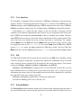
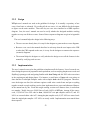
2.3.6 PICObject
The PICObject module is responsible for all pic objects. The architecture of the PICObject
module is illustrated in Figure 2.4. PICObject is the base class of PICBoundObject, PICLine,
PICArc, and PICText. PICBox, PICCircle, and PICEllipse are subclasses of PICBoundObject. PICSpline is a subclass of PICLine. These classes handle the attribute values of pic objects
as well as other information that is needed when drawing.
The main methods in PICObject are set(attr), distance(p), draw() and getCorner().
The set(attr) method is invoked by the PICCompiler module. After the IR is compiled,
all the information of the picture is stored in an object array. Refer to Section 2.4.1. When
27
PICText
PICObject
PICBoundObject
PICBox
PICArc
PICLine
PICEllipse
PICCircle
PICSpline
Figure 2.4: PICObject class diagram
PICCompiler is requested for the information of an object o, it calls o.set(attr) to assign the
attribute values attr of the specific object o.
distance(p), draw(), and getCorner() are implemented in different subclasses of PICObject. o.distance(p) calculates the distance from a specific point p to the object o. The distance
between a point p and an object o is defined as the shortest distance from p to any point on the
object o. If p is on the object o, then the distance is 0.
o.draw() draws the object o on the canvas.
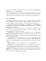
o.getCorner() gets the coordinates of a specific corner of an object o. Each object in pic
has 9 corners c, n, ne, e, se, s, sw, w, and nw. Lines and arrows have a start, an end and a
center in addition to corners. Figure 2.5 illustrates an ellipse and its corners.
2.3.7 PICCompiler
PICCompiler is the pic compiler. The original pic source code is converted into a library file
working with other Java code. PICCompiler is responsible for compiling the IR and calculating
the values of variables and grids. The main methods in PICCompiler are native methods compile(ir, center, dx, dy), getGrid(idx, center, size), and getVariable(idx, var).
compile(ir, center, dx, dy) compiles the IR, stores the objects’ information in a list
for future use. Refer to Section 2.4.1. A grid’s determinants i.e., center, dx and dy, are
28
E.n
E.nw
E.ne
E.c
E.w
E.e
E.sw
E.se
E.s
Figure 2.5: Corners of an ellipse
pic expressions made of constants, object attributes, and variables. When the IR changes, the
determinants’ values change too. Therefore, every time when the IR is compiled, the values of
the currently active grid is calculated and stored.
getGrid(idx, center, size) gets the grid values at the object whose index in the object
list is idx, and stores the values into center and size.
There are 20 variables in pic [10], e.g., boxwid and boxht. getVariable(idx, var) gets
the value of variable var at the object idx.
getAttributes(obj) gets the attributes of an object obj from the IR and stores them into a
hashtable. Finally, it returns the hashtable.
getLabel(obj) gets the label of an object obj. The method first gets the text phrase in the
IR of the object, then searches for “:” in the phrase. If there is a “:" in the phrase, the method
returns the text before the “:” as the label. Otherwise an empty string is returned.
2.3.8 Grid
The Grid module deals with the actions of grids, including defining and activating a grid. It
consists of GridAction and GridElement. In WD-pic, a session can have as many grids as the
user likes, but only one is active at a time. These grids are stored in a grid list. Refer to Section
2.4.2. Each grid has a unique name and is determined by its center , dx, and dy .
The main methods in this module are defineGrid(), activateGrid(), and getActiveGrid().
29
defineGrid() invokes the Grid Define dialog for the user to define new or existing grids. activateGrid() invokes the Grid Activate dialog for the user to activate an existing grid. If there
is no previously saved grid, it shows a warning message. getActiveGrid() gets the name of the
active grid.
2.3.9 Gravity
The Gravity module is responsible for the gravity settings, e.g., on and off, the gravity tightness
radius, gravitating to a grid point, and gravitating to a pic corner. The main methods in this
module are enableGravity(rad, grid, corner), disableGravity(), and gravitateTo(p).
enableGravity(rad, grid, corner) enables gravity with the tightness radius rad. The
parameters gird and corner are Booleans, specifying whether to gravitate to grid points and
to gravitate to pic corners, respectively. disableGravity() disables gravity. If gravity is disabled,
a pair of real numbers is taken as the indicated point.
If gravitate to grid point and gravitate to pic corner in the Gravity Setting dialog
are selected, gravitateTo(p) returns the grid point or the object corner that is closest to p. p
is the point at which the mouse was LMCed. If the object is not labeled, the Label dialog is
invoked for the user to enter a label for the object. Refer to Section 2.4.2 for details.
2.3.10 History
History is programmed to record the last four recently opened files history and the files’ grids.
Refer to Section 2.4.2. Since there is no grid information in the IR, these grids are saved in a
.wdpicrc file. Therefore, the next time that the user opens the same picture file, the grids are not
lost.
When WD-pic is first launched, the file .wdpicrc is created in the user’s home directory.
The created file, .wdpicrc, serves as the recently-opened-file history database. The names of the
recently opened files and their grids, if any, are stored. The History class maintains this history.
It has loadHistory(), saveHistory(), lookupHistory(), and updateHistory().
When WD-pic opens a file, loadHistory() is called. It retrieves the history information from
the database file and updates the Recent File list in the File menu.
saveHistory() saves the history information into the database file.
30
lookupHistory() looks in the database file to see if the most recently opened file is in the
database. If so, it gets the grid information from the database.
updateHistory() keeps the recently-opened-file list up to date and makes sure that there is no
duplicate records in the list. When the just opened file is in the list, it deletes the oldest record,
adds a new one as the most recently opened file, and re-orders the remaining records by creation
time.
2.3.11 Font
The Font module deals with font setting. There are two classes in this module, PICFont and
PICFontString. As there is no font information in the IR, all the font information is stored in a
list of PICFontString. Refer to Section 2.4.2.
PICFont handles the font settings, e.g., setting the font, style, and size. The main methods in
this class are setFont(font), setStyle(style), setSize(size), and setInvisible().
PICFontString deals with the relationship between the position of text in the IR and its font.
When the IR is changed, the positions of some characters are changed too. revalidate() is used
to keep the positions of the text in the font list updated.
2.3.12 Help
The Help module is responsible for the help information.
2.4 Implementation
2.4.1 pic code reuse
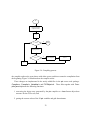
The original pic code is reused with some modifications. The original pic code works fine when
there is no syntax error in the IR, but if there are errors in the IR, it stops at the first error without
compiling the rest of the IR. We changed the code to make the compiler work in a way that it can
finish compiling an IR with errors, and it returns a correct IR. Then by comparing this IR and
the original one, we report the errors to the user. When the IR is sent to the compiler, instead of
compiling the whole IR at once, the compiler compiles it phrase by phrase. If an error occurs,
31
IR
Calculate number
of phrases (num)
i=0
i < -num ?
N
done
Y
compile phrase i
error ?
Y
reset compiler
recompile phrase
0 to i-1
N
i++
Figure 2.6: Compiling process
the compiler replaces the error phrase with white spaces, and then restarts the compilation from
the beginning. Figure 2.6 illustrates how the compiler works.
These changes are implemented in the newly added files in the pic source code package:
Compiler.c, Compiler.h, Variables.h and PICObjects.h. These files together with Compiler.java implement the following functions:
1. converting the object array generated by the pic compiler to a Java format object data
structure for the GUI to use, and
2. getting the current values of the 20 pic variables and grid determinants.
32
Variable o_srcFrom and o_srcTo are added to the obj structure in pic.h to indicate
which piece of text in the IR generated the object. The following is the C code obj structure:
typedef struct obj {
int o_type;
int o_count; /* number of things */
int o_nobj; /* index in objlist */
int o_mode; /* hor or vert */
float o_x; /* coord of "center" */
float o_y;
int o_nt1; /* 1st index in text[] for this object */
int o_nt2; /* 2nd; difference is #text strings */
int o_attr; /* HEAD, CW, INVIS, etc., go here */
int o_size; /* linesize */
int o_nhead; /* arrowhead style */
struct symtab *o_symtab; /* symtab for [...] */
float o_ddval; /* value of dot/dash expression */
float o_fillval; /* gray scale value */
/* Liz: indicate which piece of text in the IR generated this object */
int o_srcFrom;
int o_srcTo;
ofloat o_val[1]; /* actually this will be > 1 in general */
/* type is not always FLOAT!!!! */
} obj;
A new structure VarSet is defined in Variables.h to store the grid and the 20 variables
values. The following is the C code VarSet structure.
typedef struct _VarSet
{
double picVar[20];
33
double gridX0, gridY0, gridDX, gridDY;
int idx0, idx1;
struct _VarSet *next;
} VarSet;
We mentioned before that the IR is compiled phrase by phrase, so when the compiler compiles an IR phrase, it generates and adds an object to the object list. At the same time, it also gets
the grid and variable values and adds an element to the variable list. idx0 and idx1 are used to
locate the start and the end of the phrase in the IR. When the CIP moves in the IR, we search in
the variable list, to get the VarSet where idx0 ≤ cip < idx1.
For details of other pic data structures, please refer to [17].
2.4.2 Data structures and algorithms
pic data structures
Two variables are added to the original pic obj structure and a new structure VarSet is added,
as mentioned in Section 2.4.1.
Euclidean coordinate & screen coordinates
The pic compiler calculates a position, (xp , yp ), by Euclidean coordinates. However, when WDpic draws the position on the canvas, screen coordinates (xc , yc ) are used. The difference between
the Euclidean coordinates and the screen coordinates is illustrated in Figure 2.7. The origin of
the screen coordinates is at the top left corner of the screen, while the origin of the Euclidean
coordinates is at the center. Furthermore, the Y axis in the screen coordinates goes down, while
the Y axis in the Euclidean coordinates goes up.
The following formulae are used to do the translation:
xc = xp ∗ Zx + x0 ,
yc = yp ∗ Zy + y0 .
Zx , Zy , x0 , y0 are constants. |Zx | and |Zy | are used to adjust the length of unit on the canvas.
Since the Y axis in the Euclidean coordinates goes in the direction opposite of that of the Y axis
in the screen coordinates, Zy < 0.
34
(0,0)
Y
+
+
(0,0)
+
X
X
Screen coordinate
+
Y
Euclid coordinate
Figure 2.7: Euclidean coordinate & the screen coordinate
A unit in pic is 1 inch. A unit on screen is 1 pixel. To make a unit in pic look like a unit on a
17 inch monitor with 1024x768 resolution,
Zx = −Zy =
√
10242 + 7682 /17 = 75.294117647
x0 , y0 are used to adjust the position on the canvas. In this version of WD-pic,
x0 = canvasW idth/2,
y0 = canvasHeight/2.
History
The recently opened files names and their grid information are stored in a vector. In order to keep
the information when WD-pic exits, it is saved into the .wdpicrc file on the disk. Then the next
time WD-pic launches, it retrieves the history information from the .wdpicrc file. The following
is a sample record in the .wdpicrc file:
E:\WDpic\PicObject.pic
Grid1;(0,0);movewid;moveht
The first line is the full path name of the file. A grid’s name, center , dX , and dY are
separated by “;” in the second line.
35
Grid
A hashtable GridList is used to store the grids of a picture file. It is defined as following.
GridList ::= Hashtable(GridName, GridDef);
GridName ::= String;
GridDef ::= (Center, dX, dY);
Center ::= pic expression;
dX ::= pic expression;
dY ::= pic expression
The name of the grid is the key of the hashtable.
When activateGrid() is called, it searches for the contents of GridName in the GridList,
then calls EditWindow.renewLooking(). EditWindow.renewLooking() sends the grid determinants together with the IR to compile and calls MyCanvas to repaint. MyCanvas.paint()
calls Compiler.getGrid() to get the grid values from the VarSet list and draws the grid lines.
Refer to Section 2.4.1.
Gravity
The following is the pseudocode of the algorithm in the key method gravitateTo() in Gravity:
1. If gravity is off, return the pair of real numbers as the indicated point.
2. If gravitating to pic corner is selected, gravitateTo(p) does the following :
minDis = ∞ ;
q = p;
for each object o in the object list do
{
for each corner c of o do
{
dis = p.distance(c);
if dis < minDis
{
36
Figure 2.8: gravitate to
q = c;
minDis = dis;
}
}
if p.distance(c) > gravity tightness radius
return p
else return q }
3. If gravitating to grid point is selected, the point p that the user LMCed on the canvas must
be located in some grid cell, as illustrated in Figure 2.8 1 .
To figure out the values of m and n, we get the following inequalities from Figure 2.8,
(
x0 + n ∗ dx ≤ xp < x0 + (n + 1) ∗ dx
y0 + m ∗ dy ≤ yp < y0 + (m + 1) ∗ dy
p (xp , yp ) is the point that the user LMCed on the canvas. (x0 , y0 ) is the center of the grid.
The other two determinants of the grid are dx and dy.
1
Figure 2.8 was not produced by WD-pic, because it shows grid lines, whose specifications are not stored in the
IR. Instead, the figure is a portion of a screen snapshot.
37
Therefore, we can get the following formula:
(
−x0
c
n = b xpdx
yp −y0
m = b dy c
The four corners of the grid cell, in which (xp , yp ) is located, are the closest grid points to
p. Their coordinates are,
(x0 + n ∗ dx, y0 + m ∗ dy),
(x0 + n ∗ dx, y0 + (m + 1) ∗ dy)
(x0 + (n + 1) ∗ dx, y0 + m ∗ dy), (x0 + (n + 1) ∗ dx, y0 + (m + ∗dy)
The distances from (xp , yp ) to the four points are calculated. The closest point is chosen.
If the distance from p to the closest grid point is greater than the gravity tightness radius,
then p is returned as the indicated point. Otherwise the expression of the grid point is
returned.
The returned grid point expression is optimized to be more natural. For example, it is more
natural to write expression x0 + 1 ∗ dx as x0 + dx.
4. If both gravitating to pic corner and grid point are selected, choose the closer pic corner or
the grid point.
Adjusting the position of text
By default, the alignment attribute of text in pic is center, which can be changed to above,
below vertically, or ljust, rjust horizontally. enter means the text is centered at the
geometric center of the object it is associated with. The attribute ljust causes the left end to
be at the specified point(which means that the text lies to the right of the specified place), and
rjust puts the right end at the place. above and below center the text one half line space in
the given direction.
There are several horizontal lines indicating the position of a text item, as illustrated in Figure 2.9 2 .
2
Figure 2.9 was produced from a screen clump rather than by WD-pic, because it involves graphics not specified
in the IR.
38
Figure 2.9: Adjust text position
In Java, the position of a text item is indicated by its base line. If the text attribute is center,
yc is given by pic. To draw a text item whose center line is at yc , the following formula is used
to calculate the base line y (all the calculations in this section are in the screen coordinates):
y = yc + (
T extHeight
asc + dsc
asc − dsc
− dsc) = yc + (
− dsc) = yc +
2
2
2
If the text attribute is above, yb is given. So to draw a text item whose bottom line is at yb ,
y = yb − dsc
If the text attribute is below, yt is given. To draw a text item whose base line is at yb ,
y = yt + asc
The value of asc and dsc are given by a Java standard API. yc , yb , yt are as shown in
Figure 2.9.
The horizontal attributes center, ljust, and rjust are similar. The Java default is
ljust. Instead of using asc and dsc, we calculate the width of the text layout. To draw a text
item whose center is at xc ,
x = xc − wid/2
To draw an rjust text item,
x = xc − wid
Font
A vector is used to store the font information of a picture file. The structure is defined as follows.
39
FontList ::= vector of FontElement
FontElement ::= (Font, from, to)
Font ::= (font, style, size)
from ::= document position
to ::= document position
FontElement is implemented as PICFontString. The from and to record the positions
where this font setting starts and ends. Figure 2.10 3 illustrates a sample picture on the canvas.
Letter “e” is set to font Arial Bold, size 18. Letter “o” is set to Font Courier Oblique, size 24.
“World” is set to Times Italic, size 10. The rest text is in default font, default size. The related
data structures of this picture are shown in Figure 2.11.
Every time there is a change in the IR, the positions of the text items change. Therefore, the
FontList needs to be updated.
2.4.3 Miscellaneous implementation details
Run external editor
Because Java Runtime cannot run a non-windowed application, e.g., pico, and vi, from a GUI
program, the approach for runExtEditor() depends on the underlying operating system. If the
current operating system is Windows, Java Runtime.exec(editor) is called to run the external editor editor. If the current operating system is Unix, Java JNI is used to run the external
editor code in C, which is built into a library file. The Unix system calls fork() and exec() are
used [5, 16].
When runExtEditor() method is called, it first creates a temporary file file in the system’s default temporary folder. Then it calls EditWindow.exportIR(file) to copy the current complete IR to the temporary file file. It then calls exec to run the external editor with
the temporary file as the to-be-edited file. After the external editor finishes, it calls EditWindow.importIR(file) to copy the contents of the temporary file back to the edit window as the
IR.
3
Figure 2.10 was produced from a screen clump rather than by WD-pic, because it involves graphics not specified
in the IR.
40
Figure 2.10: A sample of font setting
PICObject List
PICBox
PICString
rjust
Hello
PICFontString List
PICFontString
Arial Bold, size=18
PICString
from
to
World
PICFontString
Courier Oblique, size=24
PICArrow
from
to
PICString
above
test
PICFontString
Times Italic, size=10
from
to
PICCircle
Figure 2.11: Font related data structure
41
Edit window renewlooking
renewLooking() is a very important method in EditWindow. It executes in the following steps:
1. get the active grid,
2. send the IR and grid values to compile,
3. update the font list,
4. inform MyCanvas to adjust ,
5. set the text in the EW to one of the three different attributes: normal, erroneous, and
selected,
6. get the position of the CIP and call isAtObjectPhrase() to determine which kind of object
the CIP is in,
7. update the attribute area by showing different attribute panes for different objects.
The syntax error checking is implemented based on the result of compiling IR. The compiler
compiles IR phrase by phrase, and returns a correct IR with error phrases set to white spaces.
The original IR is gotten directly from the edit window, and is stored in the variable ir0. Compiler.compile() returns a syntax-error-free IR and stores it in the variable ir. The differences
between the ir0 and ir are marked as syntax errors.
Canvas repaint
paint() is an important method in MyCanvas. It first calls drawGrid() to draw the grid. drawGrid() checks whether there is an active grid. It then gets the grid values by calling Compiler.getGrid() with CIP as a parameter and draws the grid. Next, paint() calls PICObject.draw()
to draw different objects. Finally, paint() calls drawSelected() to draw the selected objects, and
drawCIP() to draw the CIP on the canvas.
42
2.5 Evaluation
pic is targeted to draw diagrams in computer science documents. As an enhancement of pic,
WD-pic certainly does better than pic. The author used WD-pic to draw all the diagrams in this
thesis except those containing screen shots. The pic code of the figures are listed in the appendix.
The author did not know too much about pic grammar. But she found out that WD-pic was very
easy to use without too much knowledge of pic. The token buttons and the attribute buttons on
the palette are very straightforward. Furthermore, the internal representation of the diagrams are
very similar to what a human would write.
Shpilberg did a comparison between WD-pic and xfig in [17]. It shows that WD-pic is more
comfortable to use to draw simple flow diagrams. This occurs because by default pic produces
chains of drawing elements with default sizes and positions. Furthermore, once the flow diagram
is drawn, it is easier to edit. On the other hand, WD-pic is more limited than xfig in drawing
complex non-regular pictures. WD-pic’s set of primitive elements is poorer. It doesn’t have the
full set of element manipulations that xfig has.
Compared to dotty, which was mentioned in Section 1.1.3, WD-pic is more user-friendly.
You have to know the dot language well in order to draw a desired picture. But dotty does a
better job on the layout of hierarchical diagrams.
On the other hand, besides the limitations of pic, the current version of WD-pic has the
following shortcomings:
1. One cannot change the sizes of objects by direct mouse manipulations, but one can change
the sizes of objects in the edit window.
2. One cannot change the locations of objects by direct mouse manipulations, but one can
change the locations of objects in the edit window.
3. Copy, paste, cut, undo, and redo do not work with the canvas, but they work with the
edit window.
4. One cannot do search and replace in the edit window, but one can do search and replace
in an external editor.
5. Font information of the text is not saved, but the user can add the font command manually
in the IR and pass the IR to pic.
43
6. One cannot directly manipulate constructs, e.g., for, if, and block, on the canvas.
7. One cannot output pictures in a standard graph format, e.g., gif and png, or print from
WD-pic.
2.5.1 Evaluation of WD-pic relative to the pros and cons of batch and
WYSIWYG
WD-pic fixes the disadvantages of most of the WYSIWYG picture drawing program as we mentioned in Section 1.1.1.
• Changing one object in the picture will not destroy the entire picture. Because the layout
is done by pic.
• It is now easy to manipulate the objects of a category as a group. For example, the user
can use an external editor to search all the “box" in the IR and replace with “circle".
WD-pic also fixes the disadvantages of the batch programs.
• The user can now see the picture while composing its description.
• Instant feedback on the canvas reduces the errors.
2.5.2 Future work
WD-pic has met all the requirements of the customer, the author’s advisor. However, it still has
certain shortcomings. Some of them are easy to eliminate. Some are difficult, given the current
implementation of WD-pic.
More direct manipulations to the objects on the canvas can be added to the program, such as
copy, past, cut, changing sizes and locations. They are not very difficult to implement based
on the current implementation of WD-pic, since we can track the objects on the canvas and their
related positions in the IR.
Search and replace are not difficult to add to the built-in text editor in the edit window. This
would be a nice feature for WD-pic to have.
44
pic does nothing on font settings. There is no font information in the internal representation
of a picture. Because in different systems, the same font could have different names, this made
saving font information in WD-pic difficult. Direct manipulating the constructs is difficult too,
because there can be nested construct in a construct. To output pictures in standard formats such
as .ps, .jpg requires good knowledge of these formats. These are the challenging features to
implement.
45
Chapter 3
Case study
As mentioned in Section 1.2.1, one goal of this thesis is for it to be a case study in the use
of a user’s manual of a software product as requirements specification. The goal of the case
study is to see how well the user’s manual of WD-pic works as the requirement specification and
how effectively the manual can be used as a reference in the design, implementation and testing
phases. In this case study, Berry worked as the customer of WD-pic. The author of this thesis
was the software designer, developer and tester.
3.1 Project plan
The project started in the beginning of October, 2001. It was planned to be finished by the end of
July, 2002, for a total duration of 10 months. The project schedule was planned as a classic waterfall, as illustrated in Figure 3.1. The rest of this section quotes the project plan as it was written
in September, 2001, including the project schedule, requirements, design, implementation, and
testing plans.
Schedule
• preparation 1 month, from October 1 to October 31, 2001
• requirement 2 months, from November 1 to December 31, 2001
• design 1 month, from January 1 to January 31, 2002
46
10/1/01
preparation
11/1
requirement
1/1/02
design
2/1
implementation
5/1
testing
6/31
Figure 3.1: WD-pic project plan
• implementation 3 months, from February 1 to April 31, 2002
• testing 2 months, from May 1 to June 31, 2002
• others 1 month
During the whole development process, the manual will be kept up to date.
The preparation phase is to study Shpilberg’s prototype of WD-pic and all the
existing documents, and to get familiar with pic, its features, its source code, Java
Swing, and Jni.
One month flexible time is left to deal with unexpected events.
Requirements
No formal requirements specification will be written. Instead we will start by writing
a user’s manual, which will be used as the requirements specification. The software
engineer will discuss with the customer all the features and document them in the
manual. The user’s manual will be organized by use cases. It will describe all the
fundamental concepts as well and is not to be ambiguous.
47
Design
All the features in the manual will be designed. High-level design modules should be
given. The design should be clear enough to show how the modules work together.
Implementation
All the features in the manual will be implemented. Java Swing will be used to
code the GUI. Java Jni will be used to communicate between the Java coded GUI
and the C coded pic compiler.
The project will be carried out on a Unix Solaris environment.
Testing
Both black-box testing and white-box testing will be used to test the program. The
user’s manual will be used as a source of test cases for black-box testing. All the use
cases in the manual should be covered.
Unit-testing will be done on every class.
3.2 Results and introspection
The project was carried out, not exactly matching the schedule that was planned. The following
is a list of the actual milestones:
• October 2, 2001, project started
• November 1, manual started
• March 28, 2002, manual final (design started)
• April 20, design final (implementation started)
• April 22, manual first update
• May 15, first demo (basic features done)
48
10/2/01
preparation
11/1
requirement
3/28/02
design
4/20
implementation
6/11
testing
7/31
Figure 3.2: WD-pic development process
• May 16, manual second update
• June 11, second demo (all features done)
• July 31, testing end
Figure 3.2 illustrates the whole development process.
Some phases in the software development process are not exactly bounded to the clear timeline. The spare time in the previous phases of implementation was used to do research, such as
writing proof of concept (POC) code. The implementation phase was counted from writing the
main frame code of WD-pic.
White-box testing was actually combined with the implementation phase. Whenever a class
was developed, it was white-box tested. Whenever a feature was implemented, it was tested
against the use case in the manual. Thus, the testing phase in Figure 3.2 was for only black-box
testing after all the features were implemented, i.e., integration testing and system testing.
49
3.2.1 Requirements
The requirement phase took longer time than that was planned, totaling 4 months, from writing
the outline to finishing up all the features. Writing the manual was actually the process of requirements elicitation. Sometimes, a feature was proposed in a very early version, but it took
several revisions to capture what the customer really wanted. In some cases, the customer did
not know exactly what he wanted until he had seen the manual description of what he thought he
wanted. We had 11 revisions before the implementation started, and 3 more revisions later when
the author decided to change the manual from MS Word format to LATEX format. Some revisions
had only minor changes, to correct mostly grammar mistakes.
To avoid ambiguity, the final version of WD-pic user’s manual has a glossary defining 34
fundamental concepts including the program name “WD-pic”, “user”, “grid”, and “gravity”. The
main part of the manual was organized by use cases, from basic use cases to advanced features.
A step-by-step sample run was given for each use case.
Later, after implementation started, we had the following several updates.
• We planed to play an alert sound if there was a syntax error when the user tying in the edit
window. We decided to use a different color, red, to mark out the text with errors, as this
would help the user better than the sound, which is unfocused.
• A status bar was added at the bottom of the main frame to show session command errors.
The advantage of using status bar is that the user does not have to click the OK button in
the warning dialog as in other applications. The coordinates of the cursor on the canvas
can always be shown in the status bar as well.
• Selected object is high-lighted in the same selection color as the selected text in the editor
window. Then the user can easily see the relationship between the selected object on the
canvas and in the edit window.
• It was said in the manual that when the user selected an object on the canvas, the attributes
of that object would be shown in the attribute area. But in the implementation, the attribute
area is made up of attribute buttons. So it is difficult to show all the values of the attributes
in the attribute area. So we changed the attribute buttons to be used for insertion only, i.e.,
50
no matter what the existing values are, LMCing an attribute button always resets the value
of the attribute in the internal representation.
• There is no grid information in the internal representation. But the customer wants grid to
be saved. We need save the grid in a file on the hard disk. During the implementation, we
realized that we can further use this file to create a recently opened file history, which is a
popular feature in most GUI applications.
• It was said in the manual that preference setting effected inputting from the palette the same
as inputting from the keyboard. In the implementation, it is difficult to let the program
know what the token is just input from the keyboard. So we changed the preference setting
only effects the input from palette. Refer to the user’s manual for details.
• We planed to develop and execute WD-pic in a Unix environment. Because the code was
written in Java, we built a Windows version without too many changes in the code.
The first three updates actually could have been avoided if we do a better review of the manual,
but not the last four. They are related to implementation details.
Compared to writing traditional requirements specification, writing the user’s manual at the
requirement phase has the following advantages.
• The user’s manual is written at the user’s level, so it is easy for the user or the customer to
see and to tell what he or she wants. It helps requirements elicitation.
• It is also easier for the software engineer to capture what the customer wants. By writing
a use-cases-centered user’s manual, what the user inputs to the CBS and how the CBS
responds to the user are clear to the software engineer.
• By reading the use cases, the customer can verify whether these are what he or she wants.
Berry, the customer’s previous experience being a requirement engineer and a customer is
relevant to this case study because he learned how to be a demanding customer. But his previous
experience with WD-pic was irrelevant, because each time he does this, he goes for what he
believes are correct requirements. The fact that he has done WD-pic before changes only set of
features not the software engineer’s job to find out what he wants and to specify and implement
it.
51
3.2.2 Design
WD-pic user’s manual was used as the guideline for design. It is actually a repository of use
cases, from basic to advanced. By reading all the use cases, it is not difficult for the designer
to figure out the main modules. Then each key use case was visualized to a UML sequence
diagram. Last, the user’s manual was used to verify whether the designed modules working
together to carry out all the use cases. Some of these sequences diagrams are given in Appendix
B.
The user’s manual helps the design in the following ways.
• The use cases are already there, it is easy for the designer to generate the use case diagrams.
• Because a use case in the manual describes in each step what the user inputs to the CBS
or what the CBS responds to the user, it is easy for the designer to construct the sequence
(scenario) diagrams.
• The manual helps the designer to verify whether the design covers all the features in the
manual by verifying each use case.
3.2.3 Implementation
The user’s manual was used as the guideline to implement all the features. Lots of research was
done during the process of preparation and requirement, such as studying the pic source code and
Shpilberg’s prototype code and getting familiar with Java Swing and Jni. POC code was written
in the requirement and design phases. For instance, a small piece of Java code was written to
show that the C-coded pic compiler works with a simple Java-coded GUI program. Therefore,
once the design was fixed, the software engineer could write a main frame and put everything
together to make a rough working version, then implement the use cases and abstracted features
in the manual one by one. From this rough working version to all features done, it took about
two months. Totally, there are 24,091 lines of code (LOCs) in WD-pic. Among all the source
code, 13,524 LOCs are GUI code in Java, 10,464 LOCs are pic compiler code in C, and 103
LOCs are external editor code in C. Among the pic compiler code, 9,567 LOCs are reused code
from the original pic compiler. 897 LOCs are newly coded. Implementation went much faster
than expected.
52
WD-pic was planned to run only on Unix Solaris systems. However, the result shows that
after compiling the pic source code into a dynamic link library on Windows, it works with the
GUI in Java on Windows as well. So a Windows version of WD-pic was implemented as well,
with slightly different code for font setting and invoking the external editor.
3.2.4 Testing
White-box, unit testing was done to every class during the implementation phase. The user’s
manual was used as the test plan and the source of black-box test cases. Results show that the
user’s manual works as a good test plan and source of test cases. The user’s manual has all
the information that a normal test plan and test cases have, including the system requirement of
the program, the execution steps, and the correct results. Once a feature was implemented, the
software engineer did black-box testing by following the exact steps in the manual to make sure
the program worked as expected.
Most of the testing was done during implementation. Later, more black-box testing was done
when the author used WD-pic to draw all the line diagrams in this thesis. The author realized that
it was very convenient and fast to use WD-pic to draw the line diagrams if the user had the layout
of the whole diagram in mind. Users of the traditional batch pic reported the same phenomenon.
To summarize, the user’s manual helps testing by serving as the test plan and providing test
cases.
3.3 Author’s feelings during the life cycle
When I first heard the idea of using a program’s user’s manual as its requirement specification,
the idea sounded a little bit strange, because in a normal life cycle, the user’s manual is the
last document to be written. Furthermore, a user’s manual and a requirement specification have
different readers. They have different focuses on the content.
During the preparation phase, as I was getting to know more about the pic program, I was not
sure how much this GUI we were going to built on top of pic could enhance the pic program’s
functionalities. Even if a user knows the pic language well, the flexibility that the pic program
gives to the user is limited because of the limitations of the batch mode program.
53
The requirement phase was the hardest phase during the whole life cycle. The requirement
elicitation was hard. Describing the requirement to capture what the customer really wanted
was hard too. I felt that writing a good user’s manual which is to be used as a requirements
specification is as hard as writing a normal requirement specification. We didn’t save time during
the requirement phase by writing the user’s manual instead of a requirement specification. In fact,
I would say that we lost time.
Everything got paid back in the later design, implementation, and testing phases. Having
walked through the requirement elicitation process, I knew exactly what I was supposed to implement. Testing became very easy too, as the use-case-oriented manual itself was a source
of covering test cases. Implementation went much faster than expected. When I did the first
demonstration to the customer, the customer was really impressed.
When I was using WD-pic to draw the diagrams in this thesis, I realized that this software
turned out to be much better than I expected. The GUI gives users much more flexibility to draw
diagrams than the original pic program. Without too much knowledge of the pic language, I was
able to draw all kinds of line drawings easily.
Compared to projects that I did before, the requirement phase in this case study was no
easier than that in a normal life cycle. I expected that writing a user’s manual would have been
easier than writing a formal requirement specification. However, design, implementation, and
testing went much better than expected. The project finished on time and with the customer’s
satisfaction. While in my past experience, of about 5 years, usually the early requirements and
design phases went much more smoothly than in this project. However, in the past projects,
always requirements and design problems were discovered during implementation and testing.
In this project, there were much fewer problems discovered during implementation and testing,
allowing them to go very quickly.
54
Chapter 4
Conclusions
In this work, two contributions are that,
1. WD-pic was implemented and
2. a case study of using a program’s user’s manual as the program’s requirement specification
was carried out.
We have the following conclusions.
First, WD-pic follows a new paradigm for WYSIWYG direct-manipulation picture drawing
programs. It has the following advantages.
• It inherits all the advantages that the batch mode pic program has and it fixes the disadvantages of the batch and most WYSIWYG picture drawing programs.
• It provides convenient direct manipulations and directly editing the internal representation
of picture to users.
• Input by mouse or by keyboard are fully interchangeable. The user does not have to inform
the application where its next input is coming from.
• It minimizes the mouse movement.
However, because WD-pic is built on top of the pic program, its features are limited to the
features that pic can provide. Besides this, the current implementation of WD-pic also has some
other shortcomings that are independent of pic.
55
• Changing the sizes and locations of objects cannot be done by direct mouse manipulations.
• Copy, paste, cut, undo, and redo do not work with the canvas.
• Changing attributes of constructs cannot be done by direct manipulations.
• Pictures cannot be output in a standard graph format.
The first two are not real limitations. They can be overcome by using the built-in text editor.
They are not difficult to fix based on the current implementation. The later two are the challenges
for the designer of the next version.
Second, the result of our case study shows it is useful to write the user’s manual at the
requirement phase. A non-ambiguous, use-case-centered user’s manual helps the whole process
of the software development.
• The user’s manual makes an excellent requirement specification for CBSs. It specifies the
what-not-how of the CBS at the users level.
• It helps requirements elicitation by helping both the customer and the software engineer to
see what is wanted. But it cannot solve the problem that sometimes, the customer does not
know what he or she want.
• The user’s manual is a good validation tool; it helps the customer to verify the requirements
specification, and helps software engineer to verify the design and implementation.
• The user’s manual as a repository of use cases, and a useful source of a test plan and
covering test cases.
• There is no need to write the user’s manual again after the development finished! The one
used by the software engineer a lot is also easy to be read by users.
There is no completely satisfactory way to validate any SE method, but at best, our result shows that using a program’s user’s manual as its requirement specification is a promising
method. It is worth additional case studies.
56
Appendix A
pic source code of figures in the thesis
A.1 Figure 1.1
ellipse "document"
arrow
A:box "WD-pic"
arrow
ellipse "pic file"
arrow
box "pic"
arrow
box "troff"
arrow
circle rad .28
circle "picture" at last circle.c
down
arrow from A.s
circle rad .28
circle "picture" at last circle.c
57
A.2 Figure 1.2
down
A: box invis "keyboard"
B: box invis "mouse"
arrow from A.e right down boxht/2
arrow from B.e right up boxht/2
right
C: ellipse "GUI" "input"
arrow "affecting IR" "events" right 1
D: box "IR"
arrow
ellipse "pic" "compiler"
E: arrow
ellipse "GUI" "output"
line from C.se right down
line to (E.c.x-movewid, C.se.y-moveht) "affecting session" "events"
arrow to E.c
box dashed at D.e wid 5.5 ht 2
"WD-pic"above at last box .n
A.3 Figure 1.4
down
box "a"
arrow dotted
B:ellipse "b"
arrow left down "event" ljust below
circle "c"
arrow from B.s right down
ellipse wid 1 "Hello World"
58
A.4 Figure 2.3
EE: box wid 1.2 "External Editor"; move
Help: box "Help"
File: box "File" at (EE.x,-1); move boxwid
UI: box "UI"; move boxwid
Gravity: box "Gravity"
EW: box wid 1 "EditWindow" at (1.2, -2.5); move .5
Canvas: box "Canvas"
Grid: box "Grid" with .sw at Canvas.ne + (1, 0)
Font: box "Font" with .nw at Canvas.ne + (boxwid, -boxht)
left
Object: box "PICObject" with .ne at Font.sw + (0, -.3); move
Compiler: box wid 1 "PICCompiler"; move
History: box "History" at (.5, -4.2)
arrow from UI.w to EE.s
arrow from UI.n to Help.s
arrow from UI.w to File.e
arrow from UI.e to Gravity.w
arrow from UI.e to Grid.w
arrow from UI.s to EW.n
arrow from UI.s to Canvas.n
arrow from UI.s to Font.n
line from EE.s to File.n
line from File.s to EW.n
line from File.s to History.n
line from EW.e to Canvas.w
line from EW.s to Compiler.n
line from EW.s to Object.n
line from Canvas.s to Compiler.n
line from Canvas.s to Object.n
line from Canvas.e to Font.w
59
line from Canvas.e to Grid.w
line from Compiler.e to Object.w
line from History.e right 4 then up 1.5 to Grid.s
line from Grid.n to Gravity.s
line from Font.s to Object.n
line from Object.e right 1.5 then up 2 then to Gravity.e
"Legend" at (3.75, .5)
move down .3
arrow right; move; "navigate"
line at (3.75, -.15); move; "reference"
box at (4.2, 0.2) wid 1.8 ht 1 dotted
A.5 Figure 2.4
Text: box "PICText"; move .75
Object: box "PICObject"; move .75
Arc: box "PICArc"
Bound: box wid 1.2 "PICBoundObject" at (1, -1); move 1
Line: box "PICLine"
Box: box "PICBox" at (0, -2); move .5;
Ellipse: box "PICEllipse"; move .5
Circle: box "PICCircle"; move
Spline: box "PICSpline"
arrowhead = 7
arrow from Text.e to Object.w
arrow from Arc.w to Object.e
arrow from Bound.n to Object.s
arrow from Line.n to Object.s
arrow from Box.n to Bound.s
arrow from Circle.n to Bound.s
arrow from Ellipse.n to Bound.s
60
arrow from Spline.n to Line.s
A.6 Figure 2.5
E: ellipse wid 2 ht 1 "E.c"
" E.e" at E.e ljust
" E.ne" at E.ne ljust
" E.se" at E.se ljust
"E.s" at E.s below
"E.n" at E.n above
"E.sw " at E.sw rjust
"E.w " at E.w rjust
"E.nw " at E.nw rjust
A.7 Figure 2.6
down; lineht = 0.3
ellipse "IR"
arrow
box wid 1.5 "Calculate number" "of phrases (num)"
arrow
box "i = 0"
arrow
L1: line to (.7, -2.7)
line to (0, -3.0)
line to (-0.7, -2.7)
L4: line to last arrow.s
"i < -num ?" at (0, -2.7)
arrow from (0, -3.0) " Y" ljust
box wid 1.2 "compile phrase i"
arrow
61
L5:line to (.7, -4.4)
line to (0, -4.7)
line to (-0.7, -4.4)
line to last arrow.s
"error ?" at (0, -4.4)
arrow from (0, -4.7) " N" ljust
left
A: arrow 1
B:box "i++"
line from B.n up 2.05 to L4 ->
right
arrow from L1.s "N" above
circle "done"
arrow from L5.s "Y" above
box wid 1.1"reset compiler"
arrow
box ht .5 wid 1.3 "recompile phrase" "0 to i-1"
line from last box.s down .35 then to A.s ->
A.8 Figure 2.7
arrowhead = 5
L1: arrow 2
" X" at L1.end
"+" at (1.8, -0.9)
arrow from L1 down 2
"Y" rjust at last arrow.end
"+" at (-0.1, -1.8)
"(0,0)" above at (0,0)
arrow dashed from (-0.2, -1) to (2, -1)
" X" at last arrow.end
62
"+" at (1.8, 0.1)
arrow dashed from (1, -2) to (1, 0.2)
"Y" at last arrow.end rjust
"+" at (1.1, 0.1)
"(0,0)" at (1.2,-0.9)
line right from (2, -1.6)
"Screen coordinate" at (3.2, -1.6)
line dashed from (2, -1.9)
"Euclid coordinate" at (3.2, -1.9)
A.9 Figure 2.11
down
"PICFontString List" ; move .2
box wid 2 ht 1
box same
box same
x=-.25; y=-.4
"PICFontString" at (x, y)
"Arial Bold, size=18" at (x+.3, y-0.25)
"from" at (x+.2, y-0.46)
"to" at (x+.2, y -.65)
"PICFontString" at (x, y-1)
"Courier Oblique, size=24" at (x+.3, y -1.25)
F1: "from" at (x+.2, y -1.46)
T1: "to" at (x+.2, y-1.65)
"PICFontString" at (x, y-2)
"Times Italic, size=10" at (0.1, -2.65)
"from" at (0, -2.86)
"to" at (0, -3.05)
x=2.5; y=.8
63
"PICObject List" at (x, y); move .2
box wid 1.5 ht 2.2
box wid 1.5 ht 1.2
box wid 1.5 ht .75
"PICBox" at ( x-.4, y-.4) ; move .2
box wid 1 ht .7 at (x, y-0.9); move .2
box same; move.6
box same ;
"PICString" at (x-.1, y-0.7); move .2
"rjust"; move .2
"Hello"
"PICString" at (x-.1, y -1.6); move .3
"World"
"PICArrow" at (x-.3, y-2.6)
"PICString" at (x-.1, y-2.9); move .2
"above"; move .2
"test"
"PICCircle" at (x-.3, y-3.8)
line from (0.2, -0.85) to (2.37, -0.38) ->
line from (0.2, -1.05) to (2.37, -0.38) ->
line from (0.2, -1.85) to (2.5, -0.38) ->
line from (0.2, -2.05) to (2.5, -0.38) ->
line from (0.2, -2.9) to (2.25, -1.2) ->
line from (0.2, -3.06) to (2.55, -1.2) ->
A.10 Figure 3.1
boxwid=1; boxht=.4
A: box fill .2 "preparation"
B: box fill .2 ht 1.6 with .nw at last box.se "requirement"
C: box fill .2 ht .3 with .nw at last box.se "design"
64
D: box fill .2 ht .7 wid 1.2 with .nw at last box.se "implementation"
E: box fill .2 ht .7 with .nw at last box.se "testing"
line 4.6 from A.ne; "
10/2/01 "
line 3.7 from B.ne; "
11/1"
line 2.7 from C.ne; "
3/28/02"; move;move
line 1.5 from D.ne; "
4/20"
line from E.ne; "
6/11"
line from E.se; "
7/31"
spline from D.w left 3 then to B.w ->
spline from E.w left 2 to D.w ->
A.11 Figure 3.2
boxwid=1; boxht=.4
A: box fill .2 "preparation"
B: box fill .2 ht .8 with .nw at last box.se "requirement"
C: box fill .2 ht .4 with .nw at last box.se "design"
D: box fill .2 ht 1.2 wid 1.2 with .nw at last box.se "implementation"
E: box fill .2 ht .8 with .nw at last box.se "testing"
line 4.6 from A.ne; "
10/1/01 "
line 3.7 from B.ne; "
11/1"
line 2.7 from C.ne; "
1/1/02"; move;move
line 1.5 from D.ne; "
2/1"
line from E.ne; "
5/1"
line from E.se; "
6/31"
spline from C.w left 1.35 to B.w ->
spline from D.w left 2.8 then to B.w ->
spline from D.w +(0, .1) left 2 to C.w ->
spline from E.w -(0, .1) left 4.8 to B.w ->
spline from E.w left 2 to D.w ->
65
Appendix B
Sequence diagrams
B.1 Opening a file
B.2 Inserting an object
B.3 Selecting an object
B.4 Defining & activating grid
B.5 Setting font and size of text
66
Figure B.1: Sequence diagram of file open
67
Figure B.2: Sequence diagram of inserting an object
68
Figure B.3: Sequence diagram of selecing an object
69
Figure B.4: Sequence diagram of defining and activating grid
70
Figure B.5: Sequence diagram of setting font and size
71
Appendix C
WD-pic user’s manual
72
Bibliography
[1] http://www.research.att.com/sw/tools/graphviz/.
[2] http://www.graphviz.org/.
[3] http://www.omg.org.
[4] http://www.rational.com.
[5] System Calls and Library Routines, volume 2 of Unix programmer’s manual. CBS College
Publishing’s Unix System Library, 1986.
[6] Daniel M. Berry, Khuzaima Daudjee, Jing Dong, Maria Augusta Nelson, and Torsten Nelson. User’s Manual as a Requirement Specification. Technical Report CS2001-17, May
2001.
[7] Igor Finestein. Requirements specification for a large-scale telephony-based natural language speech recognition system. Master’s thesis, School of Computer Science, University
of Waterloo, Waterloo, ON, Canada, 2002.
[8] C.W. Fraser and D.R. Hanson. High-level languages facilities for low-level services. 12th
ACM Symp. on Prin. of Programming Languages, pages 217–224, 1985.
[9] Narain Gehani. Document Formatting and Typesetting on the Unix System second edition.
Silicon Press, Summit, NJ, 1987.
[10] Brian W. Kernighan. PIC - A Graphics Languages for Typesetting. Bell Laboratories,
Computer Science Technical Report No.116, December 1984.
73
[11] B.W. Kernighan. A Typesetter-independent TROFF. Computer Science Technical Report
No.116, Bell Laboratories, March 1982.
[12] Eleftherios Koutsofios. Editing Pictures with lefty. June 1996.
[13] Eleftherios Koutsofios and Stephen North. Drawing graphs with dot. AT&T Bell Laboratories, Murray Hill, NJ, February 2002. http://www.research.att.com/sw/tools/graphviz/.
[14] Eleftherios Koutsofios and Stephen C. North. Editing graphs with dotty. June 1996.
[15] Stephen C. North. Drawing graphs with NEATO, April 2002.
[16] Marc J. Rochkind. Advanced Unix Programming. Prentice-Hall, Englewood Cliffs, NJ,
1985.
[17] Faina Shpilberg. WD-pic, A WYSIWYG Direct-Manipulation pic. Master’s thesis, Faculty
of Computer Science, Technion, Haifa, Israel, July 1997.
[18] B. Srinivasan. Unix Document Processing and Typesetting. World Scientific, Singapore,
New Jersey, London, 1993.
74