1
User’s Manual as a Requirements Specification
Daniel M. Berry
Khuzaima Daudjee
Jing Dong
Maria Augusta Nelson
Torsten Nelson
{dberry,kdaudjee,jdong,magnelson,tpnelson}@uwaterloo.ca
Computer Science Department
University of Waterloo
Waterloo, Ontario N2L 3G1
Canada
May, 2001
Technical Report CS 2001-17
2001, by D.M. Berry, K. Daudjee, J. Dong, M.A. Nelson, and T. Nelson
Abstract
This paper argues that a user’s manual makes an excellent, if not the best, software requirements
specification. It discusses several lessons learned from experiences writing user’s manuals as requirements
specifications.
Keywords: ambiguity, requirements analysis, requirements elicitation, requirements validation, requirements,
scenarios, specification, test cases; use cases, user’s manual
1 Introduction—The Problem of Writing Good Requirements Specifications
This paper considers a major problem in the production of requirements for computer-based systems
(CBSs),1 that of writing a good requirements specification for the CBS. We are told to describe what and not how, to
describe the function of the CBS and not its implementation, to describe it from the user’s point of view and not the
implementer’s point of view [11, 17, 4]. This advice is correct, but carrying it out is not appreciably less difficult
than the original task. This advice is one of those things that is easier said than done.
Our work has shown us that the information that is in a properly written user’s manual is precisely what
should be in a requirements specification. The manual should describe the function of the CBS and not its implementation, to describe it from the user’s point of view and not the implementer’s point of view.2 Perhaps, it is easier
to figure out how to write a good user’s manual than a good standard feature-centered software requirement
specification (SRS) [10, 16] because of the manual’s more specific goals and audience. Also, there are many more
The focus of building a CBS is on writing the software. Hence often we forget that we are dealing with a whole
system and talk about developing software. Moreover, as we give requirements for a CBS, we also need to give
requirements for the software component in what is known as a software requirement specification (SRS). In this
paper, fully cognizant of the necessity to deal with the whole system, we often use “system” and its “software”
interchangeably, particularly since the part of the system that is most malleable is the software.
1
2
The strong structural similarity between the descriptions of a good requirements specification and a user’s manual
is entirely intentional.
1
examples of user’s manuals in the open market than there are of SRSs.
In fact, as early as 1975, Fred Brooks equated the manual with the written specifications for a computer
system product [7].
The manual must not only describe everything the user does see, including all interfaces; it must
also refrain from describing what the user does not see. That is the implementer’s business, and
there his design freedom must be unconstrained. The architect must always be prepared to show
an implementation for any feature he describes, but he must not attempt to dictate the implementation.
Also, Tom de Marco suggests in several places using user’s manuals as specifications, most notably in The Deadline
[9].
Section 2 describes a closely related problem, that of motivating the writing of a requirements
specification, and how user’s manuals may help. Section 3 gives requirements for a useful requirements
specification, and Section 4 offers the user’s manual as meeting these requirements. The quality of user’s manuals is
the subject of Section 5, and in Section 6, an outline for a good user’s manual is given. Section 7 describes some
experiences using user’s manuals as requirements specifications. The lessons learned in these and other experiences
are discussed in Section 8. Section 9 concludes the paper.
2 Motivating the Writing of a Requirements Specification
Another serious problem that faces many CBS development projects is how to even motivate the writing of
a requirements specification. Many view writing a specification as unnecessary, as a waste of time. After all, the
requirements will change as the program is being written; so, why bother? Also, in many organizations, the perception is that there is not enough time to write the requirements specification; it is necessary to get on to the coding as
quickly as possible.
One possible way to motivate requirements specification is to foster a realization that the requirements get
written anyway, as one is writing the user’s manual and the help system and as one is devising test cases, particularly if it is important to deliver a quality CBS product [19]. Writing the user’s manual requires determining what
the CBS does, i.e., its requirements. Also, in order to test a CBS, a full set of test inputs must be determined. This
determination requires figuring out what the CBS is supposed to do, i.e., the full set of features. Then it is necessary
to figure out, for each test input, the expected output. This figuring requires determining what the CBS is to do for
each test input. The complete test plan amounts to a specification of the CBS, covering at least the tested features.
The specification is as complete as the test cases.
Indeed, it is clear that in any CBS development other than for totally private use, if the normal minimum
required to release and sell the CBS is done, there is a budget for testing and writing the manual or help system.
Therefore, there are enough resources for producing a requirements specification. These resources include the time
for testing and writing the user’s manual or help system. Therefore, it is simply not true that there is not enough time
to write the requirements specification. Moreover, since an error discovered at requirements specification time costs
two orders of magnitude less to fix than the same error discovered at delivery time [5], it pays to write the requirements specifications, test cases, and user’s manual or help system at the beginning of the project.
3 Requirements for Requirements Specification
We believe that the most useful document to write during requirements engineering is the user’s manual.
When done right and at the right time, it can serve as a useful elicitation, analysis, and validation tool, and can even
serve as the final requirements specification. We are not discounting the usefulness of other requirements documents. They may be required by the customer. They may give useful information that is not contained in the user’s
manual. However, we have found the production of the user’s manual a good focal point in the requirements
2
engineering process and a good way to get on to paper at least the kernel of all the information that goes in the other
documents.
It is most important that a requirements document be readable and that it accurately and completely
describes the CBS to be built, a CBS that meets the client’s desires and needs. All else is frosting on the cake. It
must be readable because if not,
1.
2.
3.
no one will be able to judge whether the document accurately and completely describes the CBS to be
built,
no one will be able to write the software to meet the CBS’s requirements, and
no one will be able to judge whether the software meets the CBS’s requirements.
After the requirement engineers have elicited and analyzed all the information that allows writing a document that
accurately and completely describes the CBS to be built, it is their job to get this information down on paper in a
readable manner.
4 The User’s Manual as a Requirements Specification
Our favorite way to write a requirements document for a CBS that will have users is to write a user’s
manual or a collection of user’s manuals, one for each kind of user. There may be ordinary application users and
there may be system maintainer users. Note that writing a user’s manual requires a clear conception of what the
CBS is supposed to do, clear enough that the manual author can visualize user scenarios for each kind of user and
describe both
1.
2.
what the user should say to the CBS and
what the CBS will respond to the user.
Note that this information amounts to scenarios describing uses of the CBS [14, 8]. If scenarios with steps in common are collected into abstractions focused on user tasks, one gets use cases!
Even in the case of the specific user’s manual, there is a question about which detailed information should
be in it. The information in the manual depends both on the CBS whose requirements are being specified and the
people identified as users. That is, a CBS described for the user known as the system maintainer appears different
from the same CBS described for the so-called normal user of the application it represents.
5 Quality of User’s Manuals
So what does a good user’s manual look like? Well, it should be clear, not longer than necessary, and fun
to read! Actually, almost everyone knows a bad user’s manual when he or she tries to read one and cannot! There is
something of an art to writing a good user’s manual.
We personally have found the following manuals good:
the Paradox User’s Guide from Ansa [2]
The TEXbook by D.E. Knuth [26]
The C Programming Language by B.W. Kernighan and D.M. Ritchie [21]
PIC — A Graphics Language for Typesetting, Revised User Manual by B.W. Kernighan [25]
Typesetting Mathematics — User’s Guide (Second Edition) by B.W. Kernighan and L.L. Cherry [22]
A good user’s manual seems to have the following elements:
1.
2.
descriptions of underlying and fundamental concepts of the CBS,
a complete graduated set of examples, each showing
a problem situation the user faces,
some possible user responses to the problem in the form of commands to the CBS, and
the CBS’s response to these commands, and
3
3.
a systematic summary of all the commands.
The descriptions of the underlying and fundamental concepts of the CBS constitute a lexicon for the CBS and its
requirements [27]. The complete graduated set of examples constitute a defining set of use cases for the CBS [18].
Having only the third loses many readers who do not understand the concepts and turns off many readers
who get bored reading page after page after page of command syntax and semantics. Leaving out the first makes it
very hard for the author to assume and use a consistent vocabulary in writing the rest of the manual. Leaving out the
second leaves the reader without any sense of what is important and how to use the CBS to solve his or her problems.
A well-written second part makes reading the manual, even the third part, fun. The third part must be consulted in order to fully explain why the input of an example solved the problem the example claims it does. It is in
writing the first and second parts that diagrams are most useful, although we have seen good third parts that use a
collection of related diagrams, one per command, to explain the CBS’s response to every command.
A good way to organize the first part is around the abstractions that are found in the problem domain. Each
abstraction that survives the analysis should be explained in terms of
1.
2.
3.
what the objects are,
what they do, and
what is done to them.
A good way to organize the second part is around the use cases that have been identified in consultation with the
client and the users. One can use any approach to identify use cases [18, 37, 6]. Having identified them, it is useful
to decompose them into two groups,
1.
2.
basic use cases that are used frequently as components of other use cases, e.g., selection of text in a WIMP
interface, and
more complex, problem-solving use cases, e.g., changing the size and position of a selected box.
The second group can be sorted into a list by increasing complexity. This sorted list can be used as the basis for the
graduated set of examples around which to write the user’s manual.
The third part is generally a feature list, often in alphabetical order by the feature name. The organization
and contents of this part are similar to those of a traditional feature-centered SRS. Thus those, e.g. designers and
implementers, who prefer a feature-centered specification get it also.
Writing a good user’s manual takes skill, and there is no substitute for that skill. In an industrial situation,
the client and the CBS producer must hire good writers to write good conception and requirements documents.
6 Outline of a User’s Manual
According to Richard Fairley in his 1985 Software Engineering Concepts [10], a preliminary user’s manual
should be produced at requirements definition time. He proposes the following outline for the preliminary as well as
the actual manual.
1.
Introduction
Product overview and rationale
Terminology and basic features
Summary of display and report formats
Outline of the manual
2.
Getting started
Sign-on
4
Help mode
Sample run
3.
Modes of operation:
Commands
Dialogues
Reports
4.
5.
Advanced features
Command syntax and system options
Observe that Chapters 2 and 3, about Getting Started and Modes of Operation, are precisely a list of scenarios,
dressed up as a list of problems with which the user might be faced, and how to solve them with the CBS being
described. The chapter about Getting Started can show the entire scenario of a sign on to the application and a use
of the application to solve a single representative problem. It can then give the basic use cases that are used in other
use cases that are the subject of the chapter about Modes of Operation. This latter chapter can consist of the graduated set of use cases that involve using most, if not all, features.
The skills to write a good specification include general writing skills. These skills may be more important
than that of understanding the CBS to be built. Bob Glass reports how non-software-knowledgeable English majors
were successful in writing high-quality descriptions of the grubby details of programs in documentation about these
programs for maintainers [12].
7 Experiences
This section describes experiences by the authors using the user’s manual for a CBS as the requirements
specification for this CBS. The first is by the first author, based on his experience supervising a master’s thesis years
earlier, and the rest are by the other authors, based on their experiences in a graduate Requirements Engineering
Seminar taught by the first author.
7.1 flo
In 1988, Berry assisted in the writing of a user’s manual as a primary requirements document. This experience had an interesting twist to it that cannot happen for all software; however it is interesting from the total
software engineering perspective. The program was flo [38], which is a pic [23] preprocessor, which in turn is a
ditroff (device independent troff) [31, 24] preprocessor. flo’s purpose is to translate a flowchart specification that is
embedded inside a file containing ditroff input into a pic specification, which in turn is translated by the pic program
into more ditroff input. The flowchart specification is a textual algorithm in a Pascal-like notation. The generated pic
specification describes the flowchart as a picture, and the generated ditroff input draws the individual shapes of the
picture. The specified flowchart is constrained to be no larger than a single page, because the output of the ditroff
program is a sequence of programs in a page-description language such as POSTSCRIPT [1]. Each such program
prints a single page of the typeset document.
There were two roles in the development of flo, the client and the software engineer (SE). Berry, the advisor, was the client, an occasional writer of computer science theory papers, representing all people who use
flowcharts in formal papers. Berry even occasionally asked a theoretician at the Technion, Nissim Francez, for his
opinion on features. Wolfman, the student, was the SE.
To design and implement flo, Wolfman, with Berry’s feedback, wrote an initial user’s manual to describe
all features that would be implemented. They iterated on the initial user’s manual until they were satisfied that the
specified flo could be used to draw all flowcharts that they had seen in recent books and papers on theory of computing and software engineering. That is, the user’s manual became the requirements specification. This first version of
the user’s manual used hand-coded pic descriptions to draw each flowchart in the manual to look as if flo had done
it. These hand-coded pic descriptions were also Wolfman’s idea of the kind of output that flo would create for the
5
flo input.
The following steps were carried out simultaneously and repeatedly:
Wolfman implemented features in flo and commented out hand-coded examples in the manual source in
order to let the flo-generated pic code show through.
Wolfman, with Berry’s feedback, modified the manual to reflect changes in flo’s implementation that were
necessitated by discoveries made during failures to implement features as desired and as described in the
manual.
Wolfman modified the implementation to reflect changes in the manual that were indicated by discoveries
made during attempted use of the features described in the manual to write a changed manual.
The three steps were repeated until they arrived at a manual and an implementation for which
all implemented features were described in the manual,
all features described in the manual were implemented, and
the customer and user, Berry, was happy with the features and their output.
As a bonus, there was available at all times during the implementation a nice built-in test with full feature coverage,
the manual itself!
From the similarity in the structures of the papers and manuals about EQN, pic, GRAP, DAG, and flo, it
appears3 that the same approach was used by Kernighan, Bently, Cherry, and Trickey to design and implement
EQN, pic, GRAP, and DAG!
During the development, the manual underwent many, many iterations.
Any time Berry did not understand what it was saying, he complained.
Any time he could not see the purpose of something, he complained.
Many times, something it said suggested to him another option.
Many times, something it said led to his asking how to do something related.
Wolfman had to fix each of these problems, sometimes by changing or extending the language (and almost never
reducing the language!). In one case, he threw out a whole collection of attributes, “short”, “tall”, etc. in favor of
setting the size of bubbles around nodes; bubbles turned out to be a simple way to specify completely the compactness of the layout. The iteration continued until Berry could think of nothing wrong and nothing more to add!
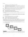
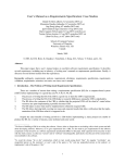
flo’s development followed a waterfall lifecycle. Unlike the traditional waterfall, this one was centered on
the production of the user’s manual.
SPECIFY
by writing
manual
DESIGN
features in
manual
CODE
features in
manual
TEST
against
manual
Appearances can be deceiving. Berry once gave a talk about flo to an audience that included Brian Kernighan, an
author of pic. Berry asked Kernighan if this approach was used to design and implement pic. Kernighan replied,
“No”.
3
6
Note the feedback into the requirements specification box (labelled “SPECIFY ...”), and that the manual gets
worked on in all steps.
The TEXbook, written by D.E. Knuth [26], is another example of a requirements specification and user’s
manual for a formatting system that is formatted by the software that it describes. That is, the source for the The
TEXbook is itself a TEX document. It served as the main test case for the formatting software since it describes all the
features that are implemented..
7.2 WD-Pic
WD-Pic (WYSIWYG, Direct-manipulation pic) is a WYSIWYG, direct-manipulation drawing program
whose internal representation is the pic language, the picture drawing language, whose processor is a pre-processor
in the ditroff family.
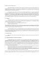
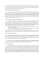
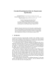
The pic language allows written descriptions of line-drawn pictures that are typical in computer-science
literature. For example, the pic specification
.PS
box "pic"
arrow
box "troff"
.PE
gets translated into ditroff instructions that cause ditroff to display
pic
troff
A key point about pic is that every graphical object has a default size, e.g., .75 inches by .5 inches for a box, and
position, to the right of the previous item. Thus, many times, the user does not have to provide explicit size and position specifications.
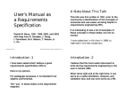
In most WYSIWYG, direct-manipulation drawing systems, after one selects a graphical item in the palette,
one has to move the mouse over to the canvas in order to specify position and size by clicking twice, once at each
corner, or clicking at one corner and dragging to and unclicking at the other corner. In WD-Pic, if everything is of
default size and position, one can draw a whole picture without ever moving the mouse from the palette. To get the
figure above, one could
click the box button,
click the quote button,
type ‘‘p’’, ‘‘i’’, ‘‘c’’, ‘‘"’’,
click the arrow button,
click the box button,
click the quote button, and
type ‘‘t’’, ‘‘r’’, ‘‘o’’, ‘‘f’’, ‘‘f’’, ‘‘"’’.
without ever having to move the mouse out of the palette or even to open up a text window. The grammar tells
WD-Pic that it should expect characters to be entered at the keyboard after the quote button is clicked.
7
Of course, in pic, the user may further qualify a graphic item with size and positioning information. Therefore, in WD-Pic, the user may provide additional size and position information, by either
clicking some other buttons on the palette
editing the internal representation, or
dragging graphical items on the canvas to the desired size and position.
WD-Pic was designed and implemented by Faina Shpilberg, one of Berry’s master’s students at the Technion.
Shpilberg built the first version of WD-Pic from requirements up with Berry as her customer. The main goal of the
thesis was to establish the requirements of WD-Pic by an extended prototyping process. For more details, please
consult Shpilberg’s thesis [35]. After Shpilberg finished her thesis, Berry thought it was time to try to get an
improved version going. Consequently, in a graduate seminar on requirements engineering taught by Berry at the
University of Waterloo, the four students that are the other authors of this paper carried out a project on improving
the first version of the WD-Pic manual. They produced three different manuals, two by one-person teams, Daudjee
and Dong, and one by a two-person team, the Nelsons. The objective of the project was to determine if the user
interface (UI) of WD-Pic could be redesigned to improve user interaction with the features of the CBS. However, as
the participants got deeper into the project, it became apparent that by understanding the structure of any particular
existing UI, thinking about improvements to that UI allowed the project participants to understand the feature for
which the UI was written. Furthermore, an improvement in the UI for a particular feature enabled the participants to
think about how new features could be added, and existing features improved. This understanding then translated to
further modifications of the UI so that the new features could be supported.
Let us consider an example. The UI for making a group of objects into a single, grouped object needed
some improvement. While changing this UI, the project participants realized that since WD-Pic supports rapid
drawing and replication of objects such as circles, lines, arrows, etc., there would be a need to replicate a grouped,
or complex, object. This led the participants to the design of a new UI item for a new feature. By naming a complex
object and saving it as a shortcut item, the user could then select the complex object through the shortcut menu item
and draw it at a desired position on the screen.
Another example is the use of a grid. When the Nelsons tried to explain to the user how to use a grid to
position objects, they noticed that enabling a grid would affect the behavior of other features in the system.
Although the grid was one of the initial requirements, the interaction with other features and subsequent effect on
their behavior was noticed only when writing the user’s manual. The Nelsons then had to study the other features
and revise their manual to reflect the feature interactions.
The above exercise illustrated some key points. The process of improving the layout and design of the UI
item for an existing feature led to the introduction of a new feature: the capability for rapid drawing of a complex
object through a shortcut menu. Previously, the shortcut menu was not a feature of WD-Pic. Another important
point is that the process of adding the new feature was iterative. The first iteration involved only improving the
existing UI. The next iteration was the design and introduction of the shortcut menu. The last iteration involved the
design of the UI for the shortcut menu.
Our experiences with writing and refining the WD-Pic User’s Manual show that the user’s manual is a
good representation of CBS requirements. The user’s manual describes more than the requirements, i.e. it captures
the requirements of the CBS as well as providing the user with step-by-step instructions of how to use the features
of the CBS. This description amounts to a statement of intent [28, 34]. Understanding this intent is critical for the
implementers, who may not have access to the specifiers. When the implementers have a question about the meaning of the specification, in the absence of access to the specifiers, knowledge of the intent helps the implementers to
figure out the intended meaning. The process of improving the user’s manual is iterative, and can serve to incorporate new features into the CBS through iterative development. It is not an accident that iterative development of a
user’s manual parallels the iterative development process of software systems. Since the user’s manual allows the
user to imagine interacting with the CBS, it serves to provide feedback on whether the CBS incorporates the
required features of the CBS. In addition, it also allows the developers to gather new requirements for the CBS. In
this context, the user’s manual can be considered to be a prototype, and the writing and improvement of the user’s
8
manual is a rapid prototyping process.
This rapid prototyping is an inexpensive process. Little or no code has to be written, and no complete, running product has to be developed. At most a few screen mockups have to be written to create illustrations for the
manual. It is a poor man’s prototype. The resulting user’s manual serves as a cost-effective and low-cost framework
and knowledge-base for the later development.
The experience led the Nelsons to observe that they did not find the process of writing the requirements
document for WD-Pic difficult, because they were not really concentrating on writing a traditional SRS document.
Instead, they were writing a user’s manual, which is a familiar document with a well-known structure. Even more
important, it is a user-centered document which promotes the requirements elicitation process. For instance, they
frequently found themselves asking questions like “So, if the user wants to move an object, can he find out how to
do it by reading the manual?” or “How will the system respond if the user tries to select a group of objects?”
7.3 Wrap Up
Thus, giving a draft user’s manual to the client and to the client’s users is a good way to elicit the “But, I
wanted x instead”s and the “But, I wanted x also”s before the CBS is implemented, i.e., to validate the requirements! The user’s manual actually serves a dual purpose,
1.
2.
aiding the elicitation of correct and complete requirements, and
being the requirements document
Note that sometimes, in order to write a user’s manual, the requirement engineer has to prototype or at least mock
up the screens so that he or she can get the nice screen pictures that you want to put in the manual. This prototype
also helps in getting the client to validate the requirements.
The manual should be written well enough that it deceives the reader into believing that the software really
exists. In fact, it’s getting the picky details worked out well enough to write the deceptive user’s manual that forces
ironing out those synergistic problems that plague many requirements, and even design, documents. We have here
yet another example of faking it [32].
8 Lessons Learned
In the course of the experiences described above and others, a number of lessons were learned. Each is discussed in detail.
8.1 Requirements and User’s Manuals for Platforms
Computing platforms, such as an operating system, are one kind of software that has a special class of users
that differs considerably from the class of users for a single application. The user of such a platform tends to be a
sophisticated user who programs applications for use by others. These applications are programmed to run on the
platform. The equivalence of requirements specification and user’s manuals holds even for these platforms. Consider the POSIX system [33], which is a standard generalization of the various UNIX platforms. It is specified by a
collection of UNIX-style manual pages describing the various kernel routines and data that are available to use to
write applications running on the platform.
1.
2.
This collection of manual pages serves as a description of the facilities that an implementation must make
available. This description gives for each kernel routine the interface it must support.
This collection of manual pages serves also as a user’s manual describing what the programmer of an
application may assume about the facilities on which the application is programmed. The description gives
for each kernel routine the interface that can be assumed by its invoker.
Any user of any POSIX compliant operating system can rely on the POSIX specification as a user’s manual for the
particular operating system. Thus, even for operating systems, a well-written user’s manual can serve as a
9
requirements specification. Of course, this style of user’s manual, aimed at the programmer of applications, may not
appear well written to the user of such an application.
8.2 Scenarios as Test Cases
Notice that Wolfman and Berry used the flo–ditroff source of the flo manual as the test case for the flo program. Of course, this benefit came from the lucky accident that flo is a batch program and they wrote the user’s
manual for flo in the formatting language of the formatting system of which flo is an integral part. In a similar
fashion, Knuth used the TEX source of The TEXbook as the main test case for the TEX program. Such direct use of
the manual as a test case is not possible in today’s WYSIWYG formatting systems. However, it is still possible to
generate test cases from the usage descriptions found in the user’s manual.
More generally, scenarios or use cases can be used to generate test cases. A little thought shows a fundamental equivalence between scenarios and test cases. Both must cover all possible inputs and uses of the CBS under
consideration, i.e., the CBS under design or test. Obtaining this full coverage is hard. The literature on testing
abounds with proof of this difficulty [3, 13, 15].
Indeed, after flo had been used about a year with no problems, an input was given that flo drew incorrectly,
collapsing two boxes into one, with their interior texts overwriting each other. Without going into too many details,
the input involved nested conditionals. It turned out that Wolfman and Berry had never tested that particular input or
any of the infinitely others that showed the problem. There were no such examples in the manual! In retrospect, it is
hard to imagine not having nested conditionals as a scenario or as a test case if the goal is complete coverage. However, neither of them ever thought of it. Perhaps they did not view this as a special case, because we had tried other
forms of nesting. Moreover, it is so common that no one else thinks of it as very special. The bug showed up one
day when they were using flo for a production job4. Completeness of scenarios and completeness of test cases are
tough to achieve, very tough! By the way, flo was fixed in a second release!
There is an added benefit of deriving test cases from the scenarios in the user’s manual. Users are strongly
influenced by the user’s manual and tend to adopt the modus operandi implicit in the way the scenarios choose to
solve problems. To the extent that the scenarios are representative of the ways that the users will use the CBS,
scenario-generated test cases will tend to cover the probable usage patterns better than arbitrarily generated test
cases.
8.3 Validation of Requirements Specifications
One key advantage of user’s manuals over traditional SRSs is in the ease of validating the requirements
document with the customer and users. This point was driven home to Berry when he compared use-case-based
user’s manual specifications of the enhanced WD-Pic with a feature-centered, traditional SRS for the same. Even
though he was quite familiar with WD-Pic from having used a previous version, even though he is thoroughly computer literate, he had a hard time understanding some specifications of features in the traditional form. He could not
see that what was specified was not quite what he wanted. He had no such problems with any of the user’s manual
specifications. He was able to spot specifications that did not correspond to his desires instantly and to describe what
was wrong and how to fix it or at least what the misunderstanding was. The clarity of the two specifications were
like night and day. In fact, he even empathized with those customers who report that they understand and accept
specifications that they were too embarrassed to admit that they had not understood at all.
When he thought about it, he understood what was the key difference in the two kinds of requirements
documents. The normal SRS describes only what the system being specified does. The user’s manual describes
conversations between the user and the system to achieve the user’s goals. Basically, the user’s manual was more
alive; Berry could see himself being the user described in the manual, and he could thus spot instantly supposed user
Isn’t that how all bugs show up?!?
4
10
behavior that did not correspond to what he would do. The normal SRS does not describe the user’s inputs and reactions. It describes only the system’s behavior in a vacuum from the user, So, Berry had no idea what user behavior
was implied. Thus, if the behavior bore any resemblance to what he thought the system would do to some input of
his, he was led to believe that the specification was what he wanted.
8.4 Manuals Should be Written in Present Tense
An important rule for writing user’s manual is to use present tense to talk about what the CBS does (notice
the present tense in this sentence!). This rule is necessary so that when it is necessary to talk about something that
happens in the future relative to when the user says something to the CBS, future tense can be used to distinguish
the future event from the user’s input. Many people write a manual for a product that has not been written yet in the
future. After all, after the CBS is implemented in the future, the user will enter some input and the CBS will do
something in response. When this is done, the writer has lost the ability to distinguish between current time and time
after that. Everything happens in the specifier’s future.
8.5 When “How” Information is Needed in Specification
Recall that we are admonished to specify What, not How when giving the requirements specification for a
CBS. Specifying only What allows the implementers the greatest freedom to choose an implementation, a How.
However, several have noted that sometimes it is necessary to give some details of the How, usually what is now
termed “Architecture” [36, 4, 30, 29]. One example described by Berry [4] is that of Knuth’s exposure of the linebreaking algorithm for TEX in The TEXbook [26], which serves as both the requirements specification and the user’s
manual. Knuth described the algorithm in the specification-and-user’s manual for two main reasons:
1.
2.
to insure that all implementations of TEX produce the same formatted output, even down to the line breaks
and spacing between words and
to give the user enough smarts about the line-breaking algorithm that he or she can exercise the commands
to effectively control the line breaking and interword spacing when he or she needs to.
It seems as though the existence of the user’s manual as the specification of TEX served as a powerful filter to make
sure that a How detail showed up in the specification only when it was necessary for the user’s effective use of TEX.
8.6 For Designers and Implementors
It can be argued that a user’s manual favors the user over the designer and implementer. The user’s
manual’s audience is the user. Certainly with a user’s manual being use-case centered, it will be hard for the
designer and implementer to identify functions to be implemented. A given function may manifest itself in several
use cases, each giving some different aspects of the functions. With only this information, the designer or implementer would have to distill the functions out of their many manifestations.
However, a good user’s manual also has a feature-centered part listing all the individual features and
describing all of the options of each. Indeed, this part is organized much as is the typical feature-centered traditional
SRS. The designer and implementer can find the functions already distilled out in this part.
8.7 Finding Ambiguities
In doing the WD-Pic project, we found that one of the most important benefits of using a user’s manual as
a requirements specification is that it is easier to find ambiguous requirements specifications. In any requirements
specification document, there may be hidden ambiguities. Each such hidden ambiguity gets subconsciously disambiguated one way by each stakeholder, e.g., the user and the implementer, who is not even aware that other meanings exist for the sentence [20]. The ambiguities are discovered only later when the CBS is delivered and the user
discovers that the implementer did not implement what he or she understood of the specification. In our experience
in the production of several user’s manual specifications of WD-Pic, the students clarified a number of misunderstanding with Berry by showing him a UI and a number of use cases. His reactions to the UI and the use cases made
11
the ambiguities and his intent clear and helped to disambiguate the ambiguities.
9 Conclusions
Writing a good requirements specification is hard, and it is hard to motivate people to write one.
The user’s manual must be written anyway. Moreover, it is an ideal requirements document in many cases
because, if it is well-written,
it is written at the level of what the user sees,
it describes the basic concepts, and
it does not describe implementation details.
That is, it is written at the right level of abstraction for a requirements specification.
In conclusion, it is our opinion that the user’s manual serves as a useful elicitation, analysis, and validation
tool, and it can even serve as a requirements specification.
Acknowledgements
Berry was supported in parts by a University of Waterloo Startup Grant and by NSERC grant NSERCRGPIN227055-00.
References
[1]
POSTSCRIPT Language Reference Manual, Second Edition, Adobe Systems Incorporated, Addison Wesley,
Reading, MA (1992).
[2]
Ansa, ANSA Paradox 1.1 for DOS, Ansa Corporation, Belmont, CA (1986).
[3]
Beizer, B., Software Testing Techniques, International Thomson Computer Press, London (1990), Second
Edition..
[4]
Berry, D.M., “What, Not How? When Is ‘How’ Really ‘What’? and Some Thoughts on Quality Requirements,” Technical Report, Computer Science Department, University of Waterloo (2001).
[5]
Boehm, B.W., Software Engineering Economics, Prentice-Hall, Englewood Cliffs, NJ (1981).
[6]
Breitman, K.K., “Evoluc¸a˜o de Cena´rios (Scenario Evolution),” Ph.D. Dissertation, Departamento de
Informa´tica, Pontif´ıcia Universidade Cato´lica, Rio de Janeiro, RJ, Brazil (May 2000).
[7]
Brooks, F.P. Jr., The Mythical Man-Month: Essays on Software Engineering, Addison Wesley, Reading, MA
(1975).
[8]
Carroll, J., Rosson, M.B., Chin, G., and Koenemann, J., “Requirements Development in Scenario-Based
Design,” IEEE Transactions on Software Engineering SE-24(12), p.1156–1170 (December 1998).
[9]
DeMarco, T., The Deadline, Dorset House, New York, NY (1997).
[10]
Fairley, R.E., Software Engineering Concepts, McGraw-Hill, New York, NY (1985).
12
[11]
Gause, D.C. and Weinberg, G.M., Exploring Requirements: Quality Before Design, Dorset House, New
York, NY (1989).
[12]
Glass, R.L., “Can English Majors Write Maintenance Documentation?,” Journal of Systems and Software
21, p.1–2 (1993).
[13]
Gourlay, J.S., “A Mathematical Framework for the Investigation of Testing,” IEEE Transactions on
Software Engineering SE-9(6), p.686–709 (November 1983).
[14]
Hooper, J.W. and Hsia, P., “Scenario-Based Prototyping for Requirements Identification,” SOFTWARE
ENGINEERING NOTES 7(5) (December 1982).
[15]
Howden, W.E., “Functional Program Testing,” IEEE Transactions on Software Engineering SE-6(2),
p.162–169 (March 1980).
[16]
IEEE, “IEEEE Recommended Practice for Software Requirements Specifications,” in ANSI/IEEE Standard
830-1998, IEEE Computer Society, Los Alamitos, CA (1998), Anonymous..
[17]
Jackson, M.A., Problem Frames: Analysing and Structuring Software Development Problems, AddisonWesley, Harlow, England (2001).
[18]
Jacobson, I., Object-Oriented Software Engineering, Addison Wesley, Reading, MA (1992).
[19]
Kamsties, E., Ho¨rmann, K., and 1998, M. Schlich, “Requirements Engineering in Small and Medium Enterprises,” Requirements Engineering Journal 3, p.84–90 (1998).
[20]
Kamsties, E., “Surfacing Ambiguity in Natural Language Requirements,” Ph.D. Dissertation, Fachbereich
Informatik, Universita¨t Kaiserslautern, Kaiserslautern, Germany (2001).
[21]
Kernighan, B.W. and Ritchie, D.M., The C Programming Language, Prentice-Hall, Inc., Englewood Cliffs,
NJ (1978).
[22]
Kernighan, B.W. and Cherry, L.L., “Typesetting Mathematics — User’s Guide (Second Edition),” Technical
Report, Bell Laboratories, Murray Hill, NJ (1978).
[23]
Kernighan, B.W., “PIC — A Language for Typesetting Graphics,” Software Practice Experience 12, p.1–20
(January 1982).
[24]
Kernighan, B.W., “A Typesetter-independent TROFF,” Computing Science Technical Report No. 97, Bell
Laboratories, Murray Hill, NJ (March 1982).
[25]
Kernighan, B.W., “PIC — A Graphics Language for Typesetting, Revised User Manual,” Computing Science Technical Report No. 116, Bell Laboratories, Murray Hill, NJ (December 1984).
[26]
Knuth, D.E., The TEXbook, Addison Wesley, Reading, MA (1988).
[27]
Leite, J.C.S.P. and Franco, A.P.M., “A Strategy for Conceptual Model Acquisition,” pp. 243–246 in
Proceedings of the First IEEE International Symposium on Requirements Engineering, San Diego, CA
(January 1993).
13
[28]
Leveson, N.G., “Intent Specification: An Approach to Building Human-Centered Specification,” in Proceedings of the Third International Conference on Requirements Engineering, IEEE Computer Society, Colorado
Springs, CO (1998).
[29]
Nuseibeh, B.A., “Weaving the Software Development Process Between Requirements and Architecture,” in
Proceedings of the ICSE2001 Workshop: From Software Requirements to Architectures (STRAW-01),
Toronto, ON, Canada (May 2001).
[30]
Nuseibeh, B.A., “Weaving Together Requirements and Architecture,” IEEE Computer 34(3), p.115–117
(March 2001).
[31]
Ossana, J.F., “NROFF/TROFF User’s Manual,” Technical Report, Bell Laboratories, Murray Hill, NJ
(October 11 1976).
[32]
Parnas, D.L. and Clements, P.C., “A Rational Design Process: How and Why to Fake It,” IEEE Transactions
on Software Engineering SE-12(2), p.196–257 (February 1986).
[33]
POSIX, “IEEE Standard Portable Operating System Interface for Computer Environments,” IEEE Std
1003.1-1988, Technical Committee on Operating Systems of the IEEE Computer Society (1988),
Anonymous..
[34]
Ravid, A., “A Method for Extracting and Stating Software Requirements that a User Interface Prototype
Contains,” M.Sc. Thesis, Faculty of Computer Science, Technion, Haifa, Israel (March 1999), Available at
ftp://www.cs.technion.ac.il/pub/misc/dberry/alon.ravid/Thesis.doc..
[35]
Shpilberg, F., “WD-pic, A WYSIWYG, Direct-Manipulation pic,” M.Sc. Thesis, Faculty of Computer Science, Technion, Haifa, Israel (July 1997).
[36]
Swartout, W. and Balzer, R., “The Inevitable Intertwining of Specification and Implementation,” Communications of the ACM 25(7), p.438–440 (July 1982).
[37]
Weidenhaupt, K., Pohl, K., Jarke, M., and Haumer, P., “Scenarios in System Development: Current Practice,” IEEE Software 15(2), p.34–45.
[38]
Wolfman, T. and Berry, D.M., “flo — A Language for Typesetting Flowcharts,” pp. 93–108 in Electronic
Publishing ’90, ed. R. Furuta, Cambridge University Press, Cambridge, UK (1990).
14