1
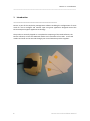
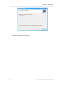
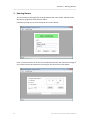
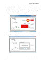
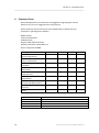
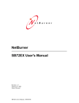
iSecure Enterprise
User and Installation Guide
Version 2
April 2012
DISUK Limited
43 Brunel Close
Drayton Fields Industrial Estate
Daventry, Northants, NN11 8RB
United Kingdom
Phone: +44 1327 313888
Email: [email protected]
Web: www.disuk.com
___________________________________________________________________
Document Release History & Revision Level
Date
12/02/2008
13/01/2010
29/09/2011
19/04/2012
Changes
Manual Created
Updated
Address change
New Features added
Revision Level
1
1a
1b
2
The contents of this manual may be revised without prior notice.
The contents of this manual shall not be disclosed in any way or reproduced in any
media without the express written permission of DISUK Limited.
All RIGHTS RESERVED, Copyright © DISUK LIMITED 2008 - 2012.
iSecure User & Installation Guide
Table of Contents
_________________________________________
1
Introduction ....................................................................................................................... 1
2
Installation.......................................................................................................................... 2
3
Running iSecure.................................................................................................................. 5
4
Setting the IP connection on a Paranoia or SecureCopy3 Unit ........................................ 11
4.1
4.2
4.3
4.4
Network Configuration ............................................................................................. 11
Operational Configuration ........................................................................................ 12
Device Network Settings ........................................................................................... 12
Device Connection Settings ...................................................................................... 13
5
Problem Solving................................................................................................................ 14
6
Comment Form ................................................................................................................ 15
7
Index ................................................................................................................................. 16
Section 1 – Introduction
_____________________________________________________________________
1
Introduction
________________________________________________
iSecure is part of the simple key management software enabling the configuration of smart
cards for use to configure and monitor tape encryption appliances designed around the
Paranoia tape encryption appliance technology.
The product is normally shipped as a complete kit comprising of the iCard Software, the
iSecure software, at least two USB card readers and a minimum of ten cards. Extra card
readers and cards can be sourced through your normal Paranoia product suppliers.
1
iSecure User and Installation Manual
Section 2 – Installation
_____________________________________________________________________
2
Installation
iSecure is the programme that allows users to monitor display and configure the Paranoia2,
ParanoiaFF, Paranoia3 and SafeTape units according to the rights granted to them by the
smartcard. iSecure cannot be run without a smartcard reader and configured smartcard.
Install the programme on the PC or server that is to be used to monitor and/or configure the
unit. To start the installation run the setup programme and follow the prompts as shown
below.
You will then be prompted to either accept the defaults or enter a new directory where you
want the programme to install. Unless you have a specific reason to change it we suggest
you accept the defaults.
2
iSecure User and Installation Manual
Section 2 – Installation
_____________________________________________________________________
Confirm the installation and select Next and the installation will now complete
3
iSecure User and Installation Manual
Section 2 – Installation
_____________________________________________________________________
The iSecure software is now installed.
4
iSecure User and Installation Manual
Section 3 – Running iSecure
_____________________________________________________________________
3
Running iSecure
To run the iSecure package place the programmed card in the reader and then select
the iSecure programme from the Start menu.
It will then prompt you to enter the PIN for the card as below.
Enter your PIN and if this is the first use and the administrator has enforced a change of
pin you will need to do this before continuing to the connection screen below.
5
iSecure User and Installation Manual
Section 3 – Running iSecure
_____________________________________________________________________
At this point enter the IP address and the description you wish to identify this specific device
by. Once you enter this the option to add a new entry or update an existing one is given as
shown below.
The iSecure application will store multiple device IPs and descriptions to allow easy selection
of different units. When using multiple units select the required one and then choose select
to connect to it.
6
iSecure User and Installation Manual
Section 3 – Running iSecure
_____________________________________________________________________
The display below shows a Full Administrator connected to a Paranoia3 with two drives
attached. The Status shows both P and K in green. This indicates that the password and the
two keys have been entered into the device. When first connecting to a device that does
not have the password and keys entered these will show red but as long as the card being
used has the ability to load the keys these indicators will change showing the progress,
yellow showing only one key has been entered and then green to show both are loaded. At
this point the unit is not set secure but keys are loaded into the unit.
The tape drives must be either unloaded or at BOT for the keys to be downloaded. If you get
the message as shown below use the system to unload or rewind the tapes to BOT and then
try again to connect to the unit.
.
7
iSecure User and Installation Manual
Section 3 – Running iSecure
_____________________________________________________________________
To set a device secure simply click on the Encrypt button and the LCD display turns green
indicating the unit is now secure.
For a multiple drive connections first select the correct drive using the Drive number button
(if only one drive is connected this will not be applicable) then select the Encrypt button. As
long as the tape is either at BOT or unloaded the display background will go green and this
drive is secure as shown below.
It should be noted that the function shown are determined when the card is generated, the
user above is a Full Administrator and can change the encryption status as well as viewing
the logs.
8
iSecure User and Installation Manual
Section 3 – Running iSecure
_____________________________________________________________________
The display below is that for a simple operator who has only the ability to view the displays
from the drive but has no ability to change anything.
The Auditor screen shown below simply allows him to check that the keys are set and to
view the logs, no indication of the actual status of the drives is available.
The View Logs button produces a log showing which operator did what and when as shown
on the following page.
9
iSecure User and Installation Manual
Section 3 – Running iSecure
_____________________________________________________________________
The latest log entry is at the top and for security reasons no name is shown but simply the
user ID. In the example shown user 2 is the Auditor, User 1 is the backup operator, User 3 is
the Full Administrator and user 4 is the operator..
The log is saved automatically and can be printed out if required. The earlier logs which
have been saved can be reviewed by using the drop down Security Logs tab, selected the
unit you are interested in and then double clicking that entry to display the full log. This log
can also be printed out.
10
iSecure User and Installation Manual
Section 4 – Problem Solving
_____________________________________________________________________
4
Setting the IP connection on a Paranoia or SecureCopy3 Unit
The Paranoia and SecureCopy3 units are supplied with an Ethernet cross over cable which
can be used to connect a laptop or PC directly to the Ethernet connector marked Network at
the rear of the unit without the need of a hub or switch. If you have access to the network
the unit can be connected in the normal way with standard cables. Do not try to use the
supplied cross over cable to connect to a standard network!
Once you are connected follow the procedure below.
4.1
Network Configuration
From the CD run IPSetup.exe. You will see a dialog box like the one below:
Click the "Search Again" button to locate your unit in the “Select a Unit” pane. If your
Paranoia3 unit does not appear, verify the power and link LED's on your MNGT connection
on the front panel are illuminated; if not, correct any cabling errors. Note that IPSetup uses a
UDP broadcast protocol similar to BOOTP and will not operate through a router.
A. If your network supports DHCP:
The assigned IP address will appear in the "Select a Unit" pane
B. If your network does not support DHCP:
Configure the IP Address and Mask fields. If you need help selecting values, see the Selecting
an IP Address section of this manual. After you have entered the values, select the "Set"
button to configure the Paranoia3 unit with the new parameters.
Verify the network connection is working properly by executing the following command
from a command prompt: "ping <ip address>" For example type “ping 10.1.1.33” (without
the quotes) at the command prompt and press the Enter key on your keyboard.
11
iSecure User and Installation Manual
Section 4 – Problem Solving
_____________________________________________________________________
4.2
Operational Configuration
Once the network parameters have been configured, you can use the web server interface
to modify setting of the Paranoia3. To access the web page on the unit, open a web browser
and enter the numeric IP Address in the address field.
4.3
Device Network Settings
SB72 Device Address
Device net mask
Device Gateway
DNS Server
12
Selects the IP address of the Paranoia3 unit. If DHCP is selected, the
Paranoia3 will obtain IP address information automatically, including
the net mask, gateway, and DNS server. If Static is selected, you need
to supply the static IP address in the edit box to the right, as well as
the other device network settings.
When using a static IP address, enter the net mask in this field.
When using a static IP address, enter the IP address of the Gateway
in this field.
When using a static IP address, enter the IP address of the DNS
Server in this Field.
iSecure User and Installation Manual
Section 4 – Problem Solving
_____________________________________________________________________
4.4
Device Connection Settings
Server Listen Port:
Select the checkbox and enter the listening port number you want the
TCP serial server to listen on for incoming connections. The default is set
to 1000
Client
Activity If no activity is detected on a TCP/IP connection the TCP server will drop
Timeout
the connection. The factory setting is 600 seconds
and Disconnect
Client
Override If no activity is detected on a TCP/IP connection within this timeout
Timeout
period, the TCP server will disconnect the current TCP/IP connection and
allow the new incoming connection request to connect. The factory
setting is 0.
Outgoing Connections If this option is enabled, the Paranoia3 will initiate a connection to an
outside
destination when the selected conditions are met
The three options are:
• Don't Initiate Connections
• Connect on Power-up
• Connect when receiving serial data
This will be set to Don’t Initiate Connections. Do not change.
Outgoing
Port Destination port number (Not normally used)
Number
Outgoing Address
Either the name (e.g. www.disuk.com) or numeric IP address (e.g.
10.1.1.2) of the destination. (Not normally used)
Outgoing Timeout
Inactivity timeout for the outgoing connection (Not normally used)
13
iSecure User and Installation Manual
Section 4 – Problem Solving
_____________________________________________________________________
5
Problem Solving
I am getting Card System Not connected message!
A. This indicates that the system has not seen the card in the card reader or the card
reader is not connected.
B. If this is on a grey background it indicates that either the USB card reader has not
been found or that no card is loaded.
C. If the card reader is not connected you will need to connect the card reader and
then close and restart the programme. If the problem persists please check that the
drivers are loaded and the device is visible in Windows.
D. If the background to the message is Red it indicates a card reader is connected but
no card is loaded in it. Loading a card will correct this.
________________________________________________
To order replacement cards or extra USB readers either contact your supplier, or contact
DISUK Ltd. direct at:
DISUK Limited
43 Brunel Close,
Drayton Fields Industrial Estate,
Daventry, Northants, NN11 8RB, U.K.
14
Phone: 44 (0)1327 313888
Web: www.disuk.com
[email protected]
iSecure User and Installation Manual
Section 5 – Comment Form
_____________________________________________________________________
6
Comment Form
We would appreciate your comments and suggestions regarding this manual.
Please list any errors or suggestions for improvement.
Please complete and send this form to the address below. We will use your
comments in planning future editions.
DISUK Limited
Technical Publications
43 Brunel Close,
Drayton Fields Industrial Estate,
Daventry, Northants, NN11 8RB, U.K.
Phone: 44 (0)1327 313888
Category
Excellent
Good
Fair
Poor
General appearance
Easy to understand
Complete
Illustrations
Technical level
Organization
Acronyms & abbreviations
Accuracy
Index
Organization:
Name:
Fax:
Manual Code
Manual Name
15
iSecure User and Installation Manual
Section 6 – Index
_____________________________________________________________________
7
Index
Auditor ................................................. 3-4
BOT ....................................................... 3-3
card reader ........................................... 4-1
COM port .............................................. 3-1
configure the unit ................................. 2-1
Connect button..................................... 3-1
Encrypt button...................................... 3-3
Full Administrator .......................... 3-3, 3-4
IP address ............................................. 3-1
16
key management .................................. 1-1
log entry ................................................ 3-4
operator ......................................... 3-3, 3-4
PIN......................................................... 3-1
Problem Solving .................................... 4-1
Status .................................................... 3-3
system administrator ..................... 3-1, 3-2
USB card reader ............................. 1-1, 4-1
View Logs .............................................. 3-4
iSecure User and Installation Manual
DISUK Limited
43 Brunel Close
Drayton Fields Industrial Estate
Daventry, Northamptonshire,
NN11 8RB, United Kingdom.
Tel: +44 1327 313 7-1
888
Email: [email protected]
iSecure User and Installation Manual