1
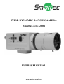
WIDE DYNAMIC RANGE CAMERA
Smartec-STC 2008
USER’S MANUAL
www.smartec-security.eu
Thank you very much for your wise choice of the Smartec Camera. Please
carefully read this Instruction Manual to keep your camera at full capacity.
CASES FOR INDEMNITY (LIMITED WARRANTY)
We shall be exempted from taking responsibility and held harmless for damage or
losses incurred by the user in the following cases.
l In the case damage or losses are caused by fire, earthquake, or other acts of God,
acts by a third party, deliberate or accidental misuse by the user, or use under
extreme operating conditions.
l In the case of indirect, additional, consequential damages (loss of business
interests, suspension of business activities) are incurred as result of malfunction
or non-function of the equipment, we shall be exempted from responsibility for
such damages.
l In the case damage or losses are caused by failure to observe the information
contained in the instructions in this instruction manual and specifications.
l In the case damage or losses are caused by use contrary to the instructions in this
instruction manual and specifications.
l In the case damage or losses are caused by malfunction or other problems
resulting from use of equipment or software that is not specified.
l In the case damage or losses are caused by repair or modification conducted by
the customer or any unauthorized third party (such as an unauthorized service
representative).
l Expenses we bear on this product shall be limited to the individual price of the
product.
RESTRICTION FOR USE
l Should the equipment be used in the following conditions or environments, give
consideration to safety measures and inform us of such usage:
1. Use of the equipment in the conditions or environment contrary to those
specified, or use outdoors.
2. Use of the equipment in applications expected to cause potential hazard to
people or property, which require special safety measures to be adopted.
l This product can be used under diverse operating conditions. Determination of
applicability of equipment or devices concerned shall be determined after
analysis or testing as necessary by the designer of such equipment or devices, or
personnel related to the specifications. Such designer or personnel shall assure
the performance and safety of the equipment or devices.
l This product is not designed or manufactured to be used for control of
equipment directly concerned with human life (*1) or equipment relating to
maintenance of public services/functions involving factors of safety (*2).
Therefore, the product shall not be used for such applications.
(*1): Equipment directly concerned with human life refers to:
l Medical equipment such as life-support systems, equipment for operating
theaters.
l Exhaust control equipment for exhaust gases such as toxic fumes or smoke.
l Equipment mandatory to be installed by various laws and regulations such as
the Fire Act or Building Standard Law.
l Equipment related to the above.
(*2): Equipment relating to maintenance of public services/functions
involving factors of safety refers to:
l Equipment for nuclear power generation.
l Equipment related to the above.
Outline
The STC-2008/1 utilizes Pixim's Digital Pixel System ® (DPS) for enterprise
security and embedded cameras based on 1/3 type WDR (Wide Dynamic Range)
sensor. The STC-2008/1 provides dramatically higher dynamic range image than
the charge-coupled devices (CCDs) or CMOS active pixel Sensors (APS) typically
used in similar video camera applications. The enhanced imaging capabilities of
DPS are based on a multi-sampling of image capture process. An analog-to-digital
converter (ADC) is designed into each pixel, and is operated simultaneously with
all other ADCs in every pixel of the sensor.
Futures
l Wide dynamic range of 120dB (maximum)
l TV system: NTSC/PAL (It switches by OSD)
l 1/3 type , 520 TV Lines, Vertical 460 TM lines (540 HTV line Equivalent).
l Minimum illumination of 0.03 lx
l The setting can be freely done with the OSD switch.
l Compact and Lightweight: 42x42x86.5mm approx 200g
l VBS, Y/C output
l Auto Iris Connector
l Mirror Reversing
l Auto White Balance
l Backlight Compensation
l CS mount
l Power source : DC12V
Configuration
(1) The camera body
(2) Accessories
Instruction manual
Bracket for tripod
1
1
1
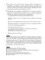
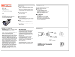
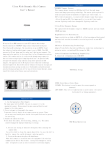
Name of parts and their functions
42
37
42
8 6 .5
8
D igital P ixel Syst em
@
‡
B
‡
D
‡
E
‡
V ID EO O U T
YC O UT
C
‡
A
‡
P O WER IN
(D C 1 2 V )
{
Ѓ
{
Ѓ
|
Ѓ
|
Ѓ
M A D E IN J A P AN
M EN U
LE NS
D igit al P ixe l Syst em
F o c us lo c k s c r ew
A. Y/C output terminal(Y/C OUT)
Used for the Y/C signal output, this terminal is connected to the Y/C input
terminal of a monitor, switcher, or the like.
B. DC12V Power input terminal
C. Video output terminal(video out)
Used for the video signal output, this terminal is connected to the video input
terminal of a monitor, switcher or the like. (VBS:1.0V(p-p)/75ohm)
D. Camera setup function switches
Refer to the Operation chapter.
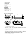
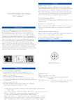
E. Auto iris lens connector
The connector is specifically used to connect the auto iris lens.
For the DC type auto iris lens.
1
3
2
4
1.CONTROL
2.CONTROL
3.DRIVE
4.DRIVE
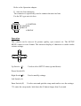
Operation
This camera can be user-set for picture quality, sync control, etc. The SETUP
MENU comes in a tree format. The onscreen display of characters is used to make
various settings.
U
L
E
R
D
Up Switch (U)
Used to select SETUP items (up and down).
Down Switch (D)
Right Switch (R)
Used to modify settings.
Left Switch (L)
Enter Switch (E)
Used to enter and quit the setup mode and to save the settings.
* To enter the setup mode, hole down the E button longer than 2 seconds.
Specifications
(1)
(2)
(3)
(4)
(5)
(6)
(7)
Model Name
Signal System
Image Sensor
Horizontal resolution
S/N ratio
Minimum illumination
Video output
(8)
(9)
(10)
(11)
(12)
(13)
(14)
(15)
(16)
Auto IRIS
Sync system
LENS mount
Power requirements
Current consumption
Dimensions
Mass
Operating temperature
Operating humidity
STC-2008/1
NTSC/PAL (It switches by OSD)
1/3 type WDR digital image sensor
520 TV lines
50dB
0.03 lx (F1.4, AGC ON, Slow shutter ON)
VBS:1.0V(p-p)/75Ω
Y/C
Y:1.0V(p-p)/75Ω
Chroma:0.286V(p-p)/75Ω
DC IRIS / Video IRIS LENS drive
Internal
CS-mount
DC12V
Approx. 2W
42(W) x 42(H) x 86.5(D) mm
Approx. 200g
-10˚ to +50˚
20 to 80 % (no condensation)
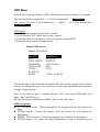
OSD Menu
To start the On Screen Display (OSD), hold the Enter button for three (3) seconds.
The current option is marked by > on a blue background.
> PRESETS
The current selection is also marked by < option > on a blue background.
<CUSTOM..
>
OSD layout
All OSD screens are made up of three sections:
1: The list on the LEFT shows this screen’s options.
2: If an option has several choices, they will appear on the RIGHT.
3: Across the bottom is the command row.
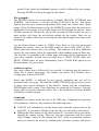
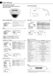
Typical OSD Screen
Smartec Main Menu
PRESETS
<NORMAL.. >
AGC
MEDIUM
LENS SELECT MANUAL
WB MODE
ATW Normal..
LOW LIGHT
ESS
VIDEO
NTSC..
ID SETUP..
MORE..
SAVE. CANCEL
This menu page is the first page presented when you hold down the center (Enter)
button. It is designed to give you easy access to the most immediate and important
settings of your camera.
Here we see that we have 7 options (presets, AGC, lens select, WB mode, low
light, video, and ID setup.).
We also have three commands available: more, save, and cancel
OSD Navigation
l UP / DOWN buttons – Moves through the list of options on the left side of the
page.
l ENTER button - Selects the option. Now the choices for the option are
highlighted
l RIGHT / LEFT buttons – Scrolls through the list of choices for this option.
l ENTER button – If a choice has more information, it will be followed by one
period. If the choice has additional options, it will be followed by two periods.
Pressing ENTER will show the page for this choice.
For example:
The PRESETS option has several choices available. INDOOR, OUTDOOR, and
NORMAL. (On occasion, it will also include CUSTOM in the list. This option
appears any time your current saved options differ from one of these three ‘quick
setups’) Press the Enter button to select the PRESETS option. Now the choices are
highlighted. Pressing the Left or Right button will flip through the choices. Since
all three options are followed by one period, pressing the Enter button on any of
these options will show the pre-defined settings for the option. There are no
choices to be made in this case, so pressing the enter button again will return to the
main menu.
Use the Down button to move to VIDEO. Press Enter to select the option and
highlight the choices. Now use the Right button to select either NTSC or PAL.
Notice that both choices have two periods. This indicates you have additional
choices for each setting. Select the appropriate video standard using the Enter key.
You will now be presented with a menu page with more choices appropriate for
your video standard. In both cases you will have a VIDEO LEVEL slider (see
MENU ITEMS below for more information), and a COLOR BAR option to test
the performance of your system.
Additional options
Any time a menu item is followed by two periods, it indicates that this option or
choice has a special menu page. For instance, the choice ATW Normal.. has a
settings page, as does ID SETUP..
Notice that MORE.. is followed by two periods, indicating that you will be
presented with a new page. The SmarTec MORE OPTIONS page gives you access
to many more special functions of the SmarTec camera and the revolutionary
PIXIM digital pixel system. These functions are organized by Exposure, Viewing,
Setup, and save/restore functions. Please take a few moments to become familiar
with all the available options.
Commands
Commands are always on the last row of the OSD page. Commands are generally
self explanatory. However, take caution of the following notes:
l CANCEL will immediately exit the menu, and return the camera state to the
last SAVE. If you make a change you do not like, you can undo it with cancel.
l Holding the Enter button on any menu option for 3 seconds will exit the menu,
keeping the current settings. This way you can experiment with the current
video settings. However, the settings are NOT saved to permanent memory
until you return to the menu (by holding enter for three seconds) and choose
SAVE.
l If the worst should happen (you SAVE settings that you dislike), you can
always recover older user settings, one of two settings profiles previously
configured, or, in the worst case scenario, restore the original factory settings.
These options are found in MORE.. / SAVE/RESTORE page.
Exiting the menu
As noted previously, there are two ways to exit the OSD menu:
l CANCEL is available on the bottom menu bar of most menu pages. Cancel will
exit the menu, and will return all settings to the last saved state.
l Holding the Enter button for three seconds at any time will exit the OSD menu.
Current settings will be preserved for testing.
However, any changes made between the last save and exiting the OSD will be lost
when
camera power is lost.
*NOTE: the original factory settings can be restored at any time by going to the
SAVE/RESTORE selection from the main OSD menu page.
MENU ITEMS
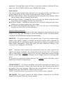
Sliders
Some OSD options include slider bars to select a value from a range.
For example: MORE / SETUP.. / IRIS.. / DC GAIN allows you to choose a value
from 0 to 255.
> DC
GAIN
0
▲
91
255
To operate the slider, highlight the selection with the Up and Down buttons, then
use the Left and Right buttons to move the pointer to the desired value.
Pressing the Down button will move to the next available slider.
Wheel
CAMERA ID in CAMERA ID SETUP is a Wheel menu item. After selecting the
option, a single character of the camera ID text is highlighted. Using the left or
right arrows will scroll through the character set (alphabet in upper and lower case,
numbers, symbols, and additional roman character support for European
languages). Pressing Enter again will move to the next character within the ID text,
and so on. UP or DOWN will leave the CAMERA ID option.
Zone Selector
The Alarm system includes Zone Selectors to set up regions of the video frame you
wish to monitor for activity. Zone selection generally works as follows:
l White Zone Outline - Select the general location using the arrow buttons. When
you are happy with the location, press Enter.
l Green Zone Outline - Expand the zone to the size you desire using the arrow
keys. When you are happy with the size, press Enter
l Red Zone Outline – Shrink the zone to the size you desire using the arrow keys.
When you a re happy with the size, press Enter.
l To exit this Zone entry, hold the Enter key. This is the only time in which holding
the Enter key does NOT exit the OSD menu.
About the Basic Selections
The SmarTec Main Menu provides all the most important camera functions on one
simple to use page. The following is a brief description of each. (For more details,
continue to the MORE menu options documentation.)
PRESETS – The preset option is the quickest way to get your camera setup.
Simply select indoor, outdoor, or normal, and all the settings will be adjusted for
these installations. If you find the picture is not the best, then you can move on and
make further adjustments. (Note that when you make additional changes, your
current preset is changed to CUSTOM)
AGC – Automatic Gain Control will automatically boost the video signal as the
light levels change. Generally, this setting affects how quickly AGC will respond,
and to what degree. Medium tends to be the best compromise between image
details in dark light, while not washing out the image caused by boosting dark
noise.
If you prefer to control this feature directly, the Custom choice will allow you to
adjust bias and limit settings directly.
LENSE SELECT – If you have installed a lens with an automatic iris control, you
can set up your lens here. Connect your lens to the lens port located on the side of
the camera. Select the lens type. If the lens does not perform as you like, go to the
MORE menu page, then SETUP / IRIS to tune your lens.
(NOTE: If you do not have an electronic iris lens, please choose Manual)
WB MODE– This option controls the White Balance functions of the PIXIM
Digital Pixel System. There are several options.
Manual allows you to adjust manually by either a Kelvin scale or individual
red/blue scales. Use this mode to compensate for unusual lighting conditions.
AWB – Auto White Balance is a white balance mode most familiar to camera
users. It performs a single balance calculation based on the target your provide.
There are no further color adjustments made to the image.
ATW Normal and ATW Extended are ‘intelligent’ White Balance modes. The
camera continuously makes calculations to give the best picture under the current
lighting conditions. Auto Tracking White modes usually provide the ‘truest’
picture.
LOW LIGHT – This setting will control the Electronic Shutter Speed built into
the PIXIM image sensor. Generally, ESS is recommended (ESS on). This mode
will dynamically adjust the shutter time to compensate for very dark conditions.
NON-ESS will turn off shutter control.
B/W ESS will switch the camera to black and white mode when ESS is taking
effect.
VIDEO STANDARD – You can select NTSC or PAL operating modes. Each
mode will allow you to control the Video Level as well as turn on the color bar test
signal output to test your video equipment.
ID SETUP – Takes you to the camera ID setup page. Here you can turn the ID on
and off, change the ID text, and change the position of the camera ID on screen.
MORE Smartec CAMERA OPTIONS
The PIXIM digital pixel system provides a wealth of features to help you get the
best possible picture. The remainder of these features are found by choosing
MORE from the main menu on the bottom of the page.
You will find each option from the main menu is also represented in other areas of
the menu system. Do not worry; choices made deep in the menu structure will
carry back to the main menu as well.
The remainder of the menu is arranged in a tree configuration. There are three
‘branches’ (plus the Save/Restore settings branch).
Each branch is summarized below. The controls available from that branch are
listed and special notes and explanations are provided.
EXPOSURE
l AGC – Automatic Gain Control
l MANUAL GAIN – provides a slider to manually adjust gain
l AE PREFs – Auto Exposure will choose either highlights or shadows within the
image to make it’s calculations
l SHUTTER LIMIT – Off, Custom, or shutters between X2 and X32. Each choice
has additional features under your control.
l BACKLIGHT – When Backlight is turned on, you can select a zone in which
the video image has backlight.
l LOW LIGHT – Low light modes include ESS, NON-ESS, and B/W ESS.
VIEWING
l FLIP – Flip the image horizontally, vertically, or both.
l BW MODE – off, Black and White, or Black and White with color Burst signal
l SHARPNESS – This menu page has several features to control the image
sharpness and quality. Detail Boost, Noise Reduction and Sharpness Control
are set from this page. In additions, Sharpness and Aperture levels are set by
slider controls.
l PRIVACY MASK SETUP – This page allows you to configure privacy masks
overlaying the video image. You can black out up to 12 parts of the screen.
Each mask can be positioned and sized using the same methods as a ZONE
selection.
SETUP
l IRIS – Lens Select, DC gain, Video Gain, and AI Threshold. These settings
affect your electronic Iris lens. Please consult your lens manual for more
information. If you do not have an electronic iris, please choose MANUAL.
The Other controls have no affect on a manual lens.
l FOCUS – Graphical, Numerical and Numerical + Graphical focus types. These
options show you focus meters using image data. After selecting a focus meter
type, you can set the focus Zone. The focus zone and data is the same
regardless of which Focus type meter you choose.
l VIDEO I/O – In addition to the Video standard, you may also configure the
Sync type, DAC output, and Digital Video Output of the camera. Some features
my not be supported by the external connections provided on your camera
model.
l AUTO-FFF – Fluorescent Flicker Free settings can be enabled. This control is
recommended for advanced users only, as it will directly affect many other
settings previously made.
l ID SETUP – Enable or disable the camera ID display, change the ID text and on
screen position.
l ACTIVITY DETECTION – Enable detection alarms, set the alarm text position,
and setup alarm zones. The camera can detect motion in any or all of up to four
zones. Each zone is sizeable and position able. In addition, you can select how
sensitive detection is, and choose to digitally pan, tilt, and zoom to the
activated zone.
SAVE / RESTORE
l RESTORE USER SETTINGS – Restores all settings to the last SAVE state
l SAVE USER SETTINGS – Save the current settings to flash memory.
l RESTORE FACTORY SETTINGS – Restore the factory default settings. If you
wish to keep use these settings, please SAVE them using SAVE USER
SETTINGS. Otherwise, upon resetting the camera or recovering from loss of
power, the camera will return to the last saved state.
l RESET CAMERA – Perform a hard reset of the camera. This has the same
affect as cycling the camera power. It will boot and load user settings from the
last SAVE.
l FW Rev – Displays the internal firmware revision.
l CONFIG SETS – The user can store up to three (3) settings configurations to be
recalled later. The BOOT configuration settings will be recalled when the
camera is powered up or RESET. This is the last SAVE state. It is the
“working” configuration. In addition, you can save two additional settings
profiles, to be recalled at any time. NOTE: Configuration sets will not be
loaded at boot time unless the user selects SAVE CURRENT AS BOOT. Finally,
the user can overwrite the current BOOT configuration with the original
factory boot settings.