1
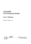
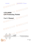
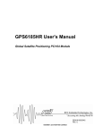
GPS140HR User's Manual
Global Satellite Positioning PC/104 Module
BDM-610020004
Rev. A
ISO9001 and AS9100 Certified
GPS140HR User's Manual
RTD EMBEDDED TECHNOLOGIES, INC.
103 Innovation Blvd
State College, PA 16803-0906
Phone: +1-814-234-8087
FAX: +1-814-234-5218
E-mail
[email protected]
[email protected]
Web Site
http://www.rtd.com
Page 2 of 30
Manual Revision History
Rev A
New manual naming method
Manual restructured
Published by:
RTD Embedded Technologies, Inc.
103 Innovation Boulevard
State College, PA 16803
Copyright 2005 by RTD Embedded Technologies, Inc.
All rights reserved
The RTD Embedded Technologies Logo is a registered trademark of RTD Embedded
Technologies. dspModule, cpuModule, and utilityModule are trademarks of RTD Embedded
Technologies. PC/104, PC/104-Plus, and PCI-104 are registered trademarks of the PC/104
Consortium. All other trademarks appearing in this document are the property of their respective
owners.
Page 3 of 30
Table of Contents
Introduction.................................................................................................................................... 7
Product Overview......................................................................................................................... 7
Board Features ............................................................................................................................ 7
GPS140HR Features............................................................................................................ 7
GPS Receiver ....................................................................................................................... 7
I/O Interfaces................................................................................................................................ 7
16C550 Compatible UART ................................................................................................... 8
Connector Description .......................................................................................................... 8
Available Options ......................................................................................................................... 8
Getting Technical Support ........................................................................................................... 8
Board Connections ..................................................................................................................... 10
Connector and Jumper Locations .............................................................................................. 10
External I/O Connections ........................................................................................................... 10
GPS Receiver Connector (to GPS module) ........................................................................... 11
Connector J1 – Differential GPS Signal Input Connector ...................................................... 11
Connector J3 – Utility I/O Connector...................................................................................... 11
Jumpers ..................................................................................................................................... 12
Base Address Jumpers (Default: 2E8) .................................................................................. 13
IRQ Jumpers (Default: IRQ 5 closed, G Jumper closed) ...................................................... 15
Reserved IRQs ................................................................................................................... 15
The G Jumper ..................................................................................................................... 16
GPS Configuration (Default: ROM = closed, NMEA closed) ................................................ 16
RST Jumper – Default Open .............................................................................................. 17
ROM Jumper – Default Closed........................................................................................... 17
NMEA Jumper – Default Closed......................................................................................... 17
Active Antenna Supply (Default: +5V)................................................................................... 18
Board Installation ........................................................................................................................ 19
Installing the Hardware .............................................................................................................. 19
Static Precautions .................................................................................................................. 19
Page 4 of 30
Steps for Installing.................................................................................................................. 19
Configuring Software ................................................................................................................. 20
Hardware Description ................................................................................................................. 21
Overview .................................................................................................................................... 21
Block Diagram............................................................................................................................ 21
The NAVMAN Jupiter GPS Receiver Module............................................................................ 22
Antenna...................................................................................................................................... 22
UART Channel ........................................................................................................................... 22
Pulse Outputs............................................................................................................................. 23
1 pulse/sec output and LED ................................................................................................... 23
10 KHz output......................................................................................................................... 23
Fuses...................................................................................................................................... 23
Software Programming ............................................................................................................... 24
Device I/O Map .......................................................................................................................... 24
Interrupts .................................................................................................................................... 24
Operation ................................................................................................................................... 25
GPS140HR Specifications .......................................................................................................... 26
GPS Receiver Specifications ..................................................................................................... 26
Physical Attributes .................................................................................................................. 26
Operational ............................................................................................................................. 26
RF Signal Environment .......................................................................................................... 26
Environmental ........................................................................................................................ 26
UART ......................................................................................................................................... 27
Fuses ......................................................................................................................................... 27
GPS140HR Operating Conditions ............................................................................................. 27
Additional Information ................................................................................................................ 28
NAVMAN Jupiter GPS Receiver ................................................................................................ 28
NMEA-0183 v2.01 Standard ...................................................................................................... 28
NAVMAN Binary Message Format ............................................................................................ 28
Serial Port Programming............................................................................................................ 28
Page 5 of 30
Interrupt Programming ............................................................................................................... 28
GPS Antenna Specifications...................................................................................................... 29
Limited Warranty ......................................................................................................................... 30
Page 6 of 30
Introduction
Product Overview
The GPS140HR is designed to provide a global positioning system (GPS) for PC/104-based
systems. Included on the GPS140HR is the NAVMAN Jupiter TU30-D400 series GPS receiver
(part number TU30-D410-021). The GPS140HR has an onboard UART chip that permits
communication with the GPS receiver module over the PC/104 bus without using other serial
ports in the PC/104 system. The GPS140HR supports NAVMAN binary protocol and National
Marine Electronics Association (NMEA-0183) v2.01 messages.
Board Features
GPS140HR Features
o
o
o
o
o
o
o
o
o
o
Direct connection to onboard GPS receiver module
Choice of GPS message formats
NAVMAN binary protocol
National Marine Electronics Association (NMEA-0183) v2.01 messages
12-satellite parallel tracking GPS receiver with fast response
Differential GPS support with external correction source
Onboard UART with flexible I/O and IRQ selection
Supports active (+5V or +12V) and passive antennas
Right angle OSX connector
Alignment with Coordinated Universal Time (UTC)
Status LED indicates 1 pulse/sec time mark output aligns with the UTC
second
10 kHz square clock aligned with UTC second is available as an output
from the board
Backup battery to store GPS receiver data while powered off
PC/104 compliant
GPS Receiver
The GPS140HR Global Positioning System (GPS) board uses a GPS receiver module for satellite
signal reception. The low power receiver outputs may use either ASCII based NMEA-0182 data
protocol or NAVMAN binary protocol depending upon the module’s selectable jumper settings.
The GPS receiver supports 12-satellite parallel-tracking as well as a fast acquisition and
reacquisition response.
I/O Interfaces
The GPS140HR can be controlled and monitored by software through the dedicated serial port
UART of the module.
A utility I/O connector provides a connection to the onboard GPS 1 pulse/sec time mark as well
as an onboard 10 KHz timing clock signal. A +12V pin on the utility connector is available to
supply power to an active antenna from an external source. If +12V is available on the PC/104
bus, this antenna supply input should not be used.
Page 7 of 30
16C550 Compatible UART
The GPS receiver module communicates through a dedicated UART channel allowing other
serial ports in the system to be free for the user. The UART is recognized by all x86 operating
systems, and does not require a special communication driver to receive data from the GPS
receiver. The base address and interrupt of the UART channel can be changed with onboard
jumpers. For information on how to install the jumpers, please refer to the “Board Connections”
chapter of this manual.
Connector Description
The GPS receiver antenna interface is a right angle OSX type miniature coaxial connector.
Connect your antenna directly to the GPS140HR antenna connector, or use a short cable inside
your enclosure to connect to a feed through connector to allow connection of the antenna to the
wall of your enclosure.
All other I/O connections to the GPS140HR use 0.1” header type terminals.
Available Options
The GPS140 is available as a starter kit, bundled with an active antenna. It may also be
purchased as an IDAN module for integration into an RTD IDAN system.
The following is a summary of the different GPS140 configurations:
Part Number
Description
GPS140HR
GPS140HR
SK-GPS140HR
GPS140HR with an active antenna
IDAN-GPS140HRS
GPS140HR mounted in an IDAN frame
IDAN-SK-GPS140HRS
GPS140HR mounted in an IDAN frame with an active
antenna
For antenna specifications, please refer to the “Additional Information” chapter of this manual.
Getting Technical Support
If you are having problems with your system, please try the following troubleshooting steps:
•
Simplify the System – Remove modules one at a time from your system to see if there
is a specific module that is causing a problem.
•
Swap Components – Try replacing parts in the system one-at-a-time with similar parts
to determine if a part is faulty or if a type of part is configured incorrectly.
If problems persist, or you have questions about configuring this product, obtain the base address
and IRQ settings of the GPS140HR and other modules in the system. After you have this
information, contact RTD Embedded Technologies via the following methods:
Phone: +1-814-234-8087
Page 8 of 30
E-Mail: [email protected]
Be sure to check the RTD web site (http://www.rtd.com) frequently for product updates, including
newer versions of the board manual and application software.
Page 9 of 30
Board Connections
Connector and Jumper Locations
The following diagram shows the location of all connectors and jumpers on the GPS140HR.
Future revisions of the GPS140HR may have cosmetic differences. For a description of each
jumper and connector, refer to the following sections.
GPS140HR Connector and Jumper Locations
Backup
Battery
GPS Correction
Signal Input (J1)
GPS
Configuration
Jumpers
GPS
Receiver
Module
Active Antenna
Supply
Jumpers
Base
Address
Jumpers
IRQ Jumpers
and G Jumper
Utility I/O
Connector (J3)
PC/104 (ISA) Connector
External I/O Connections
The following sections describe the external I/O connections of the GPS140HR.
Page 10 of 30
GPS Receiver Connector (to GPS module)
The GPS receiver module connects to the 2mm female socket connector with pins facing the
PCB. The table below shows the pin connections of the GPS receiver interface to the
GPS140HR.
Pin
1
3
5
7
9
11
13
15
17
19
Description
Antenna +V
+3.6V battery backup
GPS RESET
NMEA_SEL
NC
SER_OUT
GND
DIFF_GPS_IN
GPS
1 Pulse/Sec
Pin
2
4
6
8
10
12
14
16
18
20
Description
GPS +5V Supply
NC
NC
ROM_SEL
GND
SER_IN
NC
GND
GND
10 KHz
Connector J1 – Differential GPS Signal Input Connector
A differential GPS correction signal input can be applied to the GPS140HR for precise positioning
using the RTCM SC-04 differential signal source. The signal levels on this input are RS232. The
pin connections are shown below.
Pin
1
3
5
7
9
Description
NC
DGPS_IN
NC
NC
GND
Pin
2
4
6
8
10
Description
NC
NC
NC
NC
GND
Connector J3 – Utility I/O Connector
External power and I/O signals connect to your GPS140HR through header connector J3.
Page 11 of 30
Pin
1
3
5
7
9
Description
+5V
SER_OUT
SER_IN
BATT in: +3.6V
GND
Pin
2
4
6
8
10
Description
+12V antenna supply input
1 pulse/sec output
10 KHz output
GND
GND
If you are using a +12V active antenna you must either have a +12V present from the PC/104 bus
or you can supply it through pin 2 of the utility connector. The +12V input pin should not be used
if +12V is present on the PC/104 bus.
If the onboard GPS SRAM backup battery is not in use, pin 7 may be connected to a +3.6V
battery to provide a backup for the GPS SRAM. This pin should not be connected if the onboard
battery is in use.
Note:
Connecting the +3.6V battery backup pin can damage the GPS140HR if the onboard
battery is being used. This pin should only be used if the onboard battery is not in use.
The 1 pulse/sec and 10 KHz outputs are buffered using HCT04 buffers. The SER_OUT signal
present in pin 3 is the TTL-level output of the GSP receiver. This pin can be used to connect to
other system devices that require information from the GPS receiver.
The SER_OUT and SER_IN pins refer to data leaving and entering the GPS receiver module
respectively. The SER_IN pin carries commands to the receiver while SER_OUT transmits data
from the receiver to the UART chip. These pins are used to transmit and receive messages for
both the NMEA-0183 v2.01 and NAVMAN binary protocols.
Note:
The SER_OUT (pin 3) signal is a TTL signal that comes directly from the GPS module on
the GPS140HR. This signal does not come from the onboard UART chip, and cannot be
used as a standard serial port.
Jumpers
The following sections describe the jumper configuration options available on the GPS140HR.
For a reference that shows the location of each set of jumpers, refer to the diagram of the
GPS140HR at the beginning of this chapter. The default factory jumper settings are listed in the
following table:
Page 12 of 30
Jumper Description
Base Address Jumpers
IRQ Jumpers
GPS Configuration Jumpers
Antenna Supply Voltage
Note:
Default Factory Setting
to 2E8h
5 and G jumper closed
closed; NMEA closed
to +5V
Set
IRQ
ROM
Set
The antenna supply selection jumper must be removed if using a passive antenna.
Driving a passive antenna may cause permanent damage to the antenna.
Base Address Jumpers (Default: 2E8)
The base address selection jumpers (A3 through A8) allow you to set the base address of the
serial port UART of the GPS140HR. Any software that accesses the board will do so through
reads and writes to the I/O address set by the jumpers. To function properly, the I/O address the
software is expecting must match the base address set by the jumpers.
As shown in the figure below, A3 is located at the top end of the jumper block (towards the
PC/104 connector), while A8 is located at the bottom end (away from the PC/104 connector):
The table on the following pages shows the possible base address settings for the GPS140HR.
All base addresses are in hexadecimal. An ‘X’ indicates a closed jumper, while an empty cell
indicates an open jumper.
Base Address
(Hexadecimal)
200
208
210
218
220
228
230
238
240
248
250
258
260
A8
A7
Jumpers
A6 A5 A4
A3
X
X
X
X
X
X
X
X
X
X
X
X
Page 13 of 30
X
X
X
X
X
X
X
X
X
X
268
270
278
280
288
290
298
2A0
2A8
2B0
2B8
2C0
2C8
2D0
2D8
2E0
2E8
2F0
2F8
300
308
310
318
320
328
330
338
340
348
350
358
360
368
370
378
380
388
390
398
3A0
3A8
3B0
3B8
3C0
3C8
3D0
3D8
3E0
3E8
3F0
3F8
X
X
X
X
X
X
X
X
X
X
X
X
X
X
X
X
X
X
X
X
X
X
X
X
X
X
X
X
X
X
X
X
X
X
X
X
X
X
X
X
X
X
X
X
X
X
X
X
X
X
X
X
X
X
X
X
X
X
X
X
X
X
X
X
X
X
X
X
X
X
X
X
X
X
X
X
X
X
X
X
X
X
X
X
X
X
X
X
X
X
X
X
X
X
X
X
X
X
X
X
X
X
X
X
X
X
X
X
X
X
X
X
X
X
X
X
X
X
X
X
X
X
X
X
X
X
X
X
X
X
X
X
X
X
X
X
X
X
X
X
X
X
X
X
X
X
X
X
X
X
X
X
X
X
X
X
X
X
X
X
X
X
X
X
X
X
X
X
X
X
By default, the GPS140HR comes configured with a base address of 0x2E8.
Page 14 of 30
When selecting a base address for the GPS140HR, please observe the following guidelines:
•
Every device in your PC/104 system must have a unique base address! When selecting
a base address for the GPS140HR, make certain that it does not conflict with any other
devices.
•
Base addresses 0x3F8 and 0x2F8 are typically used by serial ports COM1 and COM2,
respectively. If you wish to use one of those base addresses, you will need to disable the
conflicting serial port.
•
Some operating systems expect UART devices to be located at the standard serial port
base addresses (0x3F8, 0x2F8, 0x3E8, and 0x2E8). Setting your GPS140HR to one of
these addresses can make system setup and configuration easier.
IRQ Jumpers (Default: IRQ 5 closed, G Jumper closed)
The IRQ selection jumpers allow you to set the IRQ used by the serial port UART of the
GPS140HR. The GPS140HR can be configured for any one of the following IRQs: 2, 3, 4, 5, 6,
7, 10, 11, 12, 14, or 15. The IRQ can be set by closing the appropriately labeled jumper on the
board.
The IRQ jumpers are located next to the PC/104 bus, as shown in the diagram at the beginning of
this chapter.
Note:
Typically IRQs can not be shared; although there are some special cases (see “The G
Jumper” later in this document). In general, the IRQ you select should not be used by
any other devices in your system.
Reserved IRQs
Some of the IRQ choices on the GPS140HR may already be used by your CPU’s onboard
peripherals. Some commonly-used IRQs are:
•
IRQ 2 is typically reserved for cascading interrupts, and therefore unavailable on most AT
class systems.
•
IRQ 3 or 4 may be set to a serial port in your system. You may need to disable a serial
port in your system prevent an IRQ conflict.
•
IRQ 5 or 7 may be used by the CPU’s parallel port. Check your CPU’s configuration to
avoid a conflict.
•
IRQ 12 is used by the PS/2 mouse. To use this IRQ, you will need to remove the PS/2
mouse from the system. Some CPUs also require a BIOS setting to disable the PS/2
mouse controller.
•
IRQ 14 is used by the primary IDE controller. To use this IRQ, you will need to disable
the primary IDE controller.
Page 15 of 30
•
IRQ 15 is used by the secondary IDE controller. To use this IRQ, you will need to disable
the secondary IDE controller.
The G Jumper
The GPS140HR supports shared interrupts as defined by the PC/104 specification. This sharing
is accomplished via the G jumper, which is located adjacent to the IRQ jumpers. The G jumper
installs a 1K-ohm resistor to pull the signal to the low state, allowing an interrupt to drive the
signal high. To share interrupts, configure the devices for the same IRQ, and close the G jumper
on one (and only one) of the devices.
When using interrupt sharing, consider the following guidelines:
•
An interrupt can only be shared if all devices on the IRQ support it. If you have two
sharing and one non-sharing device on the same IRQ, it will not work.
•
To share interrupts, the system’s drivers and operating system must support it. The
Interrupt Service routines must be written to check all devices on an IRQ when the
interrupt is detected. Many popular operating systems do not support interrupt sharing
for ISA devices.
Note:
If you are not sharing interrupts, make sure you leave the GPS140HR’s G jumper closed!
GPS Configuration (Default: ROM = closed, NMEA closed)
The jumper blocks illustrated below is used to configure the mode of operation of the GPS
receiver module. The NMEA jumper is closest to the PC/104 connector while the RST jumper is
farther away from the PC/104 connector. The location of these jumpers can also be found in the
diagram at the beginning of this chapter.
Page 16 of 30
Default Jumper Settings
A general description of the jumpers can be found below. For a detailed description of the
jumpers, please refer to the manual for the NAVMAN Jupiter GPS Receiver. The webpage of the
GPS receiver manufacture is listed in the appendix.
RST Jumper – Default Open
To reset the GPS receiver, this signal must be pulled low by installing the jumper for at least
150ns during system power up. When the system has booted, the jumper may be removed to
de-assert the GPS receiver’s reset signal. Note that the signal is a master reset, and will force
the GPS receiver to search for satellites.
Note:
If the ROM and NMEA jumpers are closed, the protocol and baud rate settings before the
last power down will be used when the reset signal is de-asserted.
ROM Jumper – Default Closed
To use satellite tracking information, navigation settings, baud rate, and the message protocol
settings before the last power down, this signal must be pulled high by installing a jumper across
the ROM pins.
When the jumper is open (removed), this pin is pulled low and the GPS receiver does not use
tracking history stored in the EEPROM on the receiver module, but instead searches for
satellites. User settings such as the baud rate and message protocol are also lost when the
system is booted with this jumper setting.
Note:
The NMEA jumper must also be closed (installed) to use the baud rate and message
protocol settings before the last power down.
NMEA Jumper – Default Closed
To use the last protocol and baud rate before the last power down, the signal must be pulled high
by installing a jumper across the NMEA pins.
Removing this jumper pulls the signal low and forces the NMEA mode as the selected protocol at
4800 baud (with no parity, 8 data bits, and 1 stop bit).
Note:
The ROM jumper must also be closed (installed) to use the baud rate and message
protocol settings before the last power down.
Page 17 of 30
Active Antenna Supply (Default: +5V)
Active GPS antennas require a supply to drive the antenna. If using a passive antenna, this
jumper should be removed. Typical supply voltages for active antennas are +5V and +12V. Set
this jumper to +5V or +12V according to the requirements of your active antenna.
If you are using a +12V active antenna you must either have a +12V present from the PC/104 bus
or you can supply it through pin 2 of the utility connector.
Note:
The supply selection jumper must be removed if using a passive antenna. Driving a
passive antenna may cause permanent damage to the antenna.
Page 18 of 30
Board Installation
Installing the Hardware
The GPS140HR can be installed into a PC/104 or PC/104-Plus stack. It can be located almost
anywhere in the stack, above or below the CPU.
Note:
If the GPS140HR is installed in a PC/104-Plus system, be sure to not break the chain of
PCI devices (such as stacking the GPS140HR between two PC/104-Plus boards).
Static Precautions
Keep your board in its antistatic bag until you are ready to install it into your system! When
removing it from the bag, hold the board at the edges, and do not touch the components or
connectors. Handle the board in an antistatic environment, and use a grounded workbench for
testing and handling of your hardware.
Steps for Installing
1. Shut down the PC/104 system and unplug the power cord.
2. Ground yourself with an anti-static strap.
3. Set the Base Address and IRQ jumpers as described in the previous chapter.
4. Line up the pins of the GPS140HR’s PC/104 connector with the PC/104 bus of the stack
and gently press the board onto the stack. The board should slide into the matching
PC/104 connector easily. Do not attempt to force the board, as this can lead to
bent/broken pins.
5. If an external antenna is required, attach it to the OSX/MSX connector. If the antenna is
an active antenna, set the voltage to +5V or +12V with the active antenna supply jumper.
Remove the active antenna supply jumper if using a passive antenna.
6. If any boards are to be stacked above the GPS140HR, install them.
7. Attach any necessary cables to the PC/104 stack.
8. Re-connect the power cord and apply power to the stack.
9. If the system has a PCI bus, enter the BIOS setup and reserve the GPS140HR’s IRQ as
a Legacy ISA resource.
10. Apply power to the system, and verify that all of the hardware is working properly. Once
power is applied, the GPS receiver will automatically initialize. A blinking LED will
indicate activity on the GPS receiver.
Page 19 of 30
Configuring Software
The GPS140HR uses a standard serial port UART for host communication. Therefore, you must
“install” a serial port under your host operating system for the GPS140HR to be recognized.
If the GPS140HR was installed using a standard serial port base address (0x3F8, 0x2F8, 0x3E8,
or 0x2E8), your operating system may detect the GPS140HR’s UART automatically. If the
GPS140HR was not auto-detected, or if it was configured with a non-standard base address, the
serial port will need to be configured manually.
Beyond the IRQ and base address, you may also need to configure the serial port parameters.
The UART interface is controlled by jumper settings.
The procedure for configuring the serial port will vary depending on the operating system.
Consult the operating system’s documentation for instructions on how to do this.
Page 20 of 30
Hardware Description
Overview
This chapter describes the major hardware building blocks of the GPS140HR. The components
discussed in this chapter include:
•
The GPS Receiver Module
•
Antenna
•
UART Channel
•
Pulse Outputs
Block Diagram
Below is a block diagram of the GPS140HR.
Page 21 of 30
The NAVMAN Jupiter GPS Receiver Module
The GPS140 includes an onboard NAVMAN Jupiter GPS Receiver Module (part number TU30D410-021). This 12-channel parallel-tracking GPS receiver provides fast Time-To-First-Fix
(TTFF) under all startup conditions. While the best TTFF performance is achieved when the time
of day and current position estimates are provided by the receiver, the flexible signal acquisitions
system takes advantage of the available information to provide fast TTFF. Acquisition is
guaranteed under all initialization conditions as long as visible satellites are not obscured.
To minimize the TTFF when primary system power is off the GPS140HR maintains the SRAM
and the Real Time Clock (RTC) using the onboard battery. In this case the shortest TTFF is
achieved by using the RTC time data and prior position data stored in the receiver’s SRAM.
The receiver supports 2D operation when less than three satellites are available or when required
by operating conditions. Altitude information required for 2D operation is determined by the
receiver or may be performed by your application software.
Communication to and from the receiver is performed through a serial channel that is connected
to the onboard UART. The receiver’s primary serial port outputs navigation data and accepts
commands from the OEM application in NMEA-0183 v2.01 format or NAVMAN binary protocol.
The secondary serial port (connector J1) is configured to accept DGPS corrections in the RTCM
SC-104 format.
This manual is not intended to be a GPS handbook. For more information on the GPS receiver
module, the NMEA-0183 format, and the NAVMAN binary protocol, please refer to the chapter
titled ”Additional Information”.
Antenna
The GPS receiver can operate from an active or passive GPS antenna to receive L1 band
frequency GPS carrier signals. Typical cable connections are made with OSX, SMA, and SMB
connections. If you connect the antenna directly to your GPS receiver without a feed through
connector through your enclosure wall you can select an antenna with an OSX connector to plug
into the OSX plug on your receiver module.
Refer to the “Jumpers” section of the manual for instructions on providing a voltage to an active
antenna.
UART Channel
GPS data is sent to the host from the receiver through a standard 16C550 compatible UART. All
x86 operating systems will recognize and support this serial communication device. The
GPS140HR uses its own onboard serial port and will not reserve serial port resources from the
system. The I/O base address and interrupt for this serial port can be flexibly set as described in
previous chapters of this manual.
After setting the base address and IRQ, you can use any communication software package or
terminal program to connect to your GPS140HR UART. The oscillator frequency is 1.8432MHz.
A reference for programming serial port UARTs can be found in the chapter titled “Additional
Information” at the end of this manual.
The UART is connected as a NULL-MODEM device. Only the TXD and RXD lines of the UART
are connected to the GPS receiver chip.
Page 22 of 30
Pulse Outputs
1 pulse/sec output and LED
The GPS receiver on the GPS140 generates a 1 pulse/sec buffered TTL level output that is
synchronized with the Coordinated Universal Time (UTC) second. The rising edge of this signal
is synchronized with the UTC within 50 ns. The receiver software produces a data message
containing the UTC time associated with each time mark pulse. This output signal is connected to
the LED as shown below.
1 pulse/sec output indicator LED
10 KHz output
A 10 KHz clock-output that is synchronized to the Coordinated Universal Time (UTC) 1 pulse/sec
output is also generated by the GPS receiver. This signal is buffered with a HCT04 buffer, and
can be used as an output to synchronize other devices.
Fuses
A 2A fuse (yellow) protects the GPS receiver from error conditions. The active antenna is
fused with a 125mA fuse (green). These fuses are on the left edge of the board.
Page 23 of 30
Software Programming
Device I/O Map
The GPS140HR is an I/O mapped device. The memory map of the GPS140HR occupies eight
bytes of host PC I/O space. This window is freely selectable by the user as defined by the base
address jumper settings. After setting the base address the user has access to the internal
resources of the GPS140HR control logic. These resources are not described in detail, since they
are mapped as a standard PC serial port. A reference for programming serial port UARTs can be
found in the chapter titled “Additional Information” at the end of this manual.
The following table shows the general I/O map of the GPS140HR:
Address
Base Addr
Base Addr + 1
Base Addr + 2
Base Addr + 3
Base Addr + 4
Base Addr + 5
Base Addr + 6
Register
TXD
RXD
BAUD div. low
BAUD div. high
IRQ enable
IRQ ID
Line control
Modem control
Line status
Modem status
Direction
Out
In
Comments
Only if control reg. Bit 7 = 0
Only if control reg. Bit 7 = 0
Only if control reg. Bit 7 = 1
Only if control reg. Bit 7 = 1
Only if control reg. Bit 7 = 0
Interrupts
Interrupts are used to notify the host CPU that an event happened on a particular device. In
general, interrupts are more efficient than a polling technique, where the CPU must query the
device status at regular intervals. Devices that use interrupts have a special connection to the
CPU, called an interrupt request line (IRQ). When the device needs the CPUs attention, it
asserts the IRQ line. Once the interrupt has been processed, the IRQ line is de-asserted.
The GPS140HR will use the jumper-selected interrupt. However, it will not actually generate
interrupts unless the Interrupt Enable register has been properly programmed.
Since the GPS140HR has a 16C550 UART, it supports all of the standard serial port interrupt
events. These events include:
•
Received data available
•
Transmit buffer empty
•
Line Status Register change
•
Modem Status Register change
A detailed explanation of serial port interrupts is beyond the scope of this manual. For more
information, consult a serial port programming reference. The chapter titled “Additional
Information” lists some resources to help the user.
Page 24 of 30
Note:
When the UART clock is running at a higher frequency, transmit/receive interrupts will
happen more frequently. Many operating systems can not process interrupts quickly
enough to handle this load. When developing your software, be sure to consider the
operating system’s limitations.
Operation
When properly configured, the GPS receiver will begin transmission of navigation data to the
UART chip on the GPS140. During operation, the GPS receiver accepts commands in the
NAVMAN binary message form or in NMEA formatted message protocol. The accepted format
depends on the settings of the ROM and NMEA GPS configuration jumpers. These jumpers are
explained in the Jumpers section of this manual.
The NAVMAN binary message format uses a binary data stream to transmit and receive data. A
binary message consists of a header and data, with a checksum value. A header is required for
each message, but some messages do not contain data.
The NMEA message protocol uses ASCII messages which conform to the NMEA0183 v2.01
specification.
A detailed explanation of the NAVMAN binary message format and NMEA-0183 protocol is
beyond the scope of this manual. For more information, please refer to the resources listed in the
appendix.
Page 25 of 30
GPS140HR Specifications
GPS Receiver Specifications
Physical Attributes
o
o
o
Size: 3.6”L x 3.8”W x 0.6”H (90mm L x 96mm W x 15mm H)
Weight: 0.24bs (0.10 Kg)
Power Consumption: 1.125W @ 5 VDC Typical (NMEA mode in DOS)
Operational
GPS receiver
NAVMAN Jupiter TU30-D410-021
Update rate
Once per second
Reacquisition
2s typical with a 10s blockage
RTCM SC-104 differential compatibility
Direct connection to RS232 input
Supported data protocols
National Marine Electronics Association (NMEA0183) v2.01, or NAVMAN binary protocol
Power requirement
+5V, preamplifier passthrough up to +12V for
active antenna
RF Signal Environment
RF input
1575.42MHz (L1 band) at levels
-130dBW and –163dBW
Connector
OSX high retention female connector
Burnout protection
-10dBW signal with a bandwidth of 10MHz
centered about the L1 carrier frequency
Environmental
Cooling
Convection
Operating temperature
-40º to +85ºC
Humidity
RH up to 95% non-condensing
Altitude
-1000 to 60.000 ft
Maximum Vehicle Dynamic
500m/s acquisition and navigation
Vibration
Survival 18G peak
Page 26 of 30
UART
UART compatibility
16C550
Oscillator frequency
1.8432MHz
Connection
Null Modem
Base addresses
32
Interrupts
2, 3, 4, 5, 7, 10, 11, 12, 14 and 15
Fuses
GPS receiver
2A
Active antenna
125mA
GPS140HR Operating Conditions
Operating temperature range
-40º to +85ºC
Storage temperature range
-55 C to +125 C
Humidity
RH up to 95% non-condensing
Altitude
-1000 to 30.000 ft
o
Page 27 of 30
o
Additional Information
NAVMAN Jupiter GPS Receiver
For a downloadable datasheet for the Jupiter GPS receiver (part number TU30-D410-021) visit
the receiver manufacturer’s website:
http://www.navman.com/
NMEA-0183 v2.01 Standard
For a complete description on the National Marine Electronics Association (NMEA-0183) v2.01
protocol visit the NMEA website:
http://www.nmea.org/
A detailed description of the NMEA data messages supported by the Jupiter GPS receiver can be
found in the Zodiac GPS Receiver Family Designer’s Guide. This document is available on the
web under the downloads section of the TDC webpage:
http://www.tdc.co.uk/
NAVMAN Binary Message Format
A detailed description of the serial data interface is contained in the Zodiac GPS Receiver Family
Designer’s Guide. This document is available on the web under the downloads section of the
TDC webpage:
http://www.tdc.co.uk/
Serial Port Programming
For more information about programming serial port UARTs, consult the following book:
Serial Communications Developer’s Guide
By Mark Nielson
ISBN: 0764545701
Interrupt Programming
For more information about interrupts and writing interrupt service routines, refer to the following
book:
Interrupt-Driven PC System Design
By Joseph McGivern
ISBN: 0929392507
Page 28 of 30
GPS Antenna Specifications
The RTD part numbers SK-GPS140HR and IDAN-SK-GPS140HRS come with the following
active antenna
Manufacturer:
Matsushita Electric
Part number:
GPS024OSX01C02
Page 29 of 30
Limited Warranty
RTD Embedded Technologies, Inc. warrants the hardware and software products it manufactures
and produces to be free from defects in materials and workmanship for one year following the
date of shipment from RTD EMBEDDED TECHNOLOGIES, INC. This warranty is limited to the
original purchaser of product and is not transferable.
During the one year warranty period, RTD EMBEDDED TECHNOLOGIES will repair or replace,
at its option, any defective products or parts at no additional charge, provided that the product is
returned, shipping prepaid, to RTD EMBEDDED TECHNOLOGIES. All replaced parts and
products become the property of RTD EMBEDDED TECHNOLOGIES. Before returning any
product for repair, customers are required to contact the factory for an RMA number.
THIS LIMITED WARRANTY DOES NOT EXTEND TO ANY PRODUCTS WHICH HAVE BEEN
DAMAGED AS A RESULT OF ACCIDENT, MISUSE, ABUSE (such as: use of incorrect input
voltages, improper or insufficient ventilation, failure to follow the operating instructions that are
provided by RTD EMBEDDED TECHNOLOGIES, "acts of God" or other contingencies beyond
the control of RTD EMBEDDED TECHNOLOGIES), OR AS A RESULT OF SERVICE OR
MODIFICATION BY ANYONE OTHER THAN RTD EMBEDDED TECHNOLOGIES. EXCEPT AS
EXPRESSLY SET FORTH ABOVE, NO OTHER WARRANTIES ARE EXPRESSED OR
IMPLIED, INCLUDING, BUT NOT LIMITED TO, ANY IMPLIED WARRANTIES OF
MERCHANTABILITY AND FITNESS FOR A PARTICULAR PURPOSE, AND RTD EMBEDDED
TECHNOLOGIES EXPRESSLY DISCLAIMS ALL WARRANTIES NOT STATED HEREIN. ALL
IMPLIED WARRANTIES, INCLUDING IMPLIED WARRANTIES FOR MECHANTABILITY AND
FITNESS FOR A PARTICULAR PURPOSE, ARE LIMITED TO THE DURATION OF THIS
WARRANTY. IN THE EVENT THE PRODUCT IS NOT FREE FROM DEFECTS AS
WARRANTED ABOVE, THE PURCHASER'
S SOLE REMEDY SHALL BE REPAIR OR
REPLACEMENT AS PROVIDED ABOVE. UNDER NO CIRCUMSTANCES WILL RTD
EMBEDDED TECHNOLOGIES BE LIABLE TO THE PURCHASER OR ANY USER FOR ANY
DAMAGES, INCLUDING ANY INCIDENTAL OR CONSEQUENTIAL DAMAGES, EXPENSES,
LOST PROFITS, LOST SAVINGS, OR OTHER DAMAGES ARISING OUT OF THE USE OR
INABILITY TO USE THE PRODUCT.
SOME STATES DO NOT ALLOW THE EXCLUSION OR LIMITATION OF INCIDENTAL OR
CONSEQUENTIAL DAMAGES FOR CONSUMER PRODUCTS AND SOME STATES DO NOT
ALLOW LIMITATIONS ON HOW LONG AN IMPLIED WARRANTY LASTS, SO THE ABOVE
LIMITATIONS OR EXCLUSIONS MAY NOT APPLY TO YOU.
THIS WARRANTY GIVES YOU SPECIFIC LEGAL RIGHTS, AND YOU MAY ALSO HAVE
OTHER RIGHTS WHICH VARY FROM STATE TO STATE.
Page 30 of 30