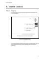
1
Model PCAP-NaI
Multichannel Analyzer
9232102B 9/00
User’s Manual
Copyright 2000, Packard BioScience Company. All rights reserved.
The material in this manual, including all information, pictures,
graphics and text, is the property of Packard BioScience Company
and is protected by U.S. copyright laws and international copyright
conventions. No material in this manual may be reproduced,
published, translated, distributed or displayed by any means without
written permission from Canberra Industries, a division of Packard
BioScience Company.
Canberra Industries, 800 Research Parkway, Meriden, CT 06450
Tel: 203-238-2351 FAX: 203-235-1347 http://www.canberra.com
The information in this manual describes the product as accurately as
possible, but is subject to change without notice.
Printed in the United States of America.
Table of Contents
1. Introduction . . . . . . . . . . . . . . . . . . . . . . . . . . . . . 1
2. Setup and Configuration . . . . . . . . . . . . . . . . . . . . . . 2
Unpacking . . . . . . . . . . . . . . . . . . . . . . . . . . . . . . . . . . . . . . . . . . . . . . 2
Installation . . . . . . . . . . . . . . . . . . . . . . . . . . . . . . . . . . . . . . . . . . . . . . 2
Changing the I/O Address . . . . . . . . . . . . . . . . . . . . . . . . . . . . . . . . . . . . 2
Setting the Card’s Input . . . . . . . . . . . . . . . . . . . . . . . . . . . . . . . . . . . . . 2
Installing the Card . . . . . . . . . . . . . . . . . . . . . . . . . . . . . . . . . . . . . . . . 2
Installing the Software. . . . . . . . . . . . . . . . . . . . . . . . . . . . . . . . . . . . . . 3
Rear Panel Controls . . . . . . . . . . . . . . . . . . . . . . . . . . . . . . . . . . . . . . . . . 4
LLD/ULD . . . . . . . . . . . . . . . . . . . . . . . . . . . . . . . . . . . . . . . . . . . . 4
Zero . . . . . . . . . . . . . . . . . . . . . . . . . . . . . . . . . . . . . . . . . . . . . . . 5
Creating an MCA Input Definition . . . . . . . . . . . . . . . . . . . . . . . . . . . . . . . . . 5
The MID Wizard . . . . . . . . . . . . . . . . . . . . . . . . . . . . . . . . . . . . . . . . . . . 6
The MCA Input Definition Editor . . . . . . . . . . . . . . . . . . . . . . . . . . . . . . . . . . 9
The MCA Adjust Screens . . . . . . . . . . . . . . . . . . . . . . . . . . . . . . . . . . . . . 10
Stabilizer Parameters . . . . . . . . . . . . . . . . . . . . . . . . . . . . . . . . . . . . . . 11
Amplifier Parameters. . . . . . . . . . . . . . . . . . . . . . . . . . . . . . . . . . . . . . 12
High Voltage Parameters. . . . . . . . . . . . . . . . . . . . . . . . . . . . . . . . . . . . 13
Acquire Setup Screen. . . . . . . . . . . . . . . . . . . . . . . . . . . . . . . . . . . . . . . . 13
A. Specifications. . . . . . . . . . . . . . . . . . . . . . . . . . . . 14
Board Configuration . . . . . . . . . . . . . . . . . . . . . . . . . . . . . . . . . . . . . . . . 14
Processor . . . . . . . . . . . . . . . . . . . . . . . . . . . . . . . . . . . . . . . . . . . . . . 14
Input . . . . . . . . . . . . . . . . . . . . . . . . . . . . . . . . . . . . . . . . . . . . . . . . 14
Output. . . . . . . . . . . . . . . . . . . . . . . . . . . . . . . . . . . . . . . . . . . . . . . . 14
Data Acquisition . . . . . . . . . . . . . . . . . . . . . . . . . . . . . . . . . . . . . . . . . . 14
ADC . . . . . . . . . . . . . . . . . . . . . . . . . . . . . . . . . . . . . . . . . . . . . . . . 14
Presets . . . . . . . . . . . . . . . . . . . . . . . . . . . . . . . . . . . . . . . . . . . . . . . 15
Preamplifier. . . . . . . . . . . . . . . . . . . . . . . . . . . . . . . . . . . . . . . . . . . . . 15
Amplifier . . . . . . . . . . . . . . . . . . . . . . . . . . . . . . . . . . . . . . . . . . . . . . 15
High Voltage . . . . . . . . . . . . . . . . . . . . . . . . . . . . . . . . . . . . . . . . . . . . 15
SCA . . . . . . . . . . . . . . . . . . . . . . . . . . . . . . . . . . . . . . . . . . . . . . . . . 16
Power . . . . . . . . . . . . . . . . . . . . . . . . . . . . . . . . . . . . . . . . . . . . . . . . 16
Physical . . . . . . . . . . . . . . . . . . . . . . . . . . . . . . . . . . . . . . . . . . . . . . . 16
Evironmental . . . . . . . . . . . . . . . . . . . . . . . . . . . . . . . . . . . . . . . . . . . . 16
Ordering Information . . . . . . . . . . . . . . . . . . . . . . . . . . . . . . . . . . . . . . . . 16
B. Internal Controls . . . . . . . . . . . . . . . . . . . . . . . . . . 17
Internal Jumpers . . . . . . . . . . . . . . . . . . . . . . . . . . . . . . . . . . . . . . . . . . 17
Setting the I/O Address . . . . . . . . . . . . . . . . . . . . . . . . . . . . . . . . . . . . . . . 18
C. Installation Considerations . . . . . . . . . . . . . . . . . . . . 22
ii
1. Introduction
The PCAP-NaI is a personal computer plug-in MCA card that contains everything
needed to support an NaI(Tl) spectroscopy system. High voltage, preamplifier, shaping
amplifier, gain stabilizer, ADC, and memory are all contained in a compact, ISA-bus
half-length assembly. Power consumption is less than 10 W.
There is no need for NIM or external stand-alone electronics. Just connect the high
voltage and signal cable to the detector, boot your computer, start the Genie-2000
software, and you are ready to acquire spectral data. Using the PCAP-NaI is easy.
High voltage, amplifier coarse and fine gains, ADC conversion gain and many other
functions are easily controlled by the computer through software adjust screens.
Every PCAP-NaI comes equipped with its own on-board digital gain stabilizer. You’ll
never have to worry about spectrum drift again! The stabilizer continuously monitors
your system to compensate for any external variables like room temperature that can
affect its precision.
Computer Control
This capability allows the user to maintain multiple system setups, downloading the
required configuration as needed. No manual dial adjustments are necessary. The system is ready for routine sample analysis by simply calling up predefined calibration/setup files.
Software support is available with the Genie-2000 platform, under Windows NT or
Windows 95/98. The supporting software extends the capabilities of the system to
meet a wide range of application requirements.
Software Support
The PCAP-NaI is fully supported by Canberra’s trend setting Genie-2000 software
product family. Genie-2000 supports a wide range of time proven spectral analysis algorithms, modern spectrum display and user interface as well as a variety of special
applications programs. Genie-2000 software solutions are available for applications
ranging as widely as laboratory gamma and alpha spectroscopy, waste measurement,
whole body counting and nuclear safeguards.
Setup and Configuration
2. Setup and Configuration
Unpacking
Unpack your PCAP-NaI board and examine it carefully for evidence of damage caused
in transit. If damage is found notify Canberra and the carrier immediately.
Installation
The PCAP-NaI card has three internal controls: a 10-pole DIP switch for setting the
card’s I/O address and two jumpers for setting the source of the input signal.
Changing the I/O Address
The I/O Address is set at the factory to 210H (52810). If another address is required, refer to “Setting the I/O Address” on page 18 before the card is physically installed in
the computer.
Setting the Card’s Input
The card is shipped from the factory for use with a NaI detector with a passive tube
base, such as Canberra’s Model 2007 PM Tube Base. To use the PCAP-NaI with an
external shaping amplifier, refer to “Internal Jumpers” on page 17.
Installing the Card
The card may be installed in the target PC by using the following procedure:
1. Turn OFF the power to the computer to prevent damage to the computer and
the PCAP-NaI card.
2. Remove the cover from the computer. Consult the reference manual supplied
with the computer for proper instructions on removing the cover.
3. The PCAP-NaI may be inserted into any available slot. Remove the retaining
screw from the slot’s blank panel and remove the panel.
4. To insert the PCAP-NaI card, the end of the card with the connectors must be
tilted downward as the card is inserted into the computer. When the
connectors have cleared the rear-panel cutout, rotate the card until it’s
2
Installation
parallel to and centered above the computer’s motherboard connector. Use
moderate downward pressure to seat the card in the connector.
5. Replace the retaining screw in the PCAP-NaI card’s rear panel and tighten.
6. Replace the computer cover by reversing the procedure in step 2.
7. Reapply power to the computer.
Installing the Software
Refer to the Genie-2000 Operations Manual, Appendix A, “Software Installation”, for
instructions on installing the Genie-2000 Basic Spectroscopy Software.
3
Setup and Configuration
Rear Panel Controls
The PCAP-NaI card’s rear-panel 15-turn potentiometers set the ADC discriminators
and the zero intercept (see Figure 1). These controls can be adjusted by using a small
screwdriver.
Figure 1 Rear Panel
LLD/ULD
The PCAP-NaI contains a circuit which examines each signal coming from the connected detector to see if the signal is greater in amplitude than the LLD (lower Level
Discriminator) setting and lesser in amplitude than the ULD (upper Level
Discrimintaor) settings. Signals (events) outside this window are discarded.
4
Creating an MCA Input Definition
Zero
In most cases, channel one of the spectrum is made to correspond to a zero energy input (zero intercept). This means that the location of a given event in the spectrum is
linearly and directly proportional to the height of the input pulse. In some cases, however, the Zero control can be used to offset the spectrum by up to –1.5% to +4.5% of
the ADC’s current conversion gain.
Creating an MCA Input Definition
After you have installed the card and the Genie-2000 software, the first step in using
your PCAP-NaI board is to create an MCA Input Definition (MID).
MID Wizard or MID Editor?
For most cases, you’ll use the MID Wizard to help you set up your Input Definition
quickly and easily.
If your Input Definition is more complex than the MID Wizard was designed to handle
(i.e. multiple PCAP-NaI boards or other MCAs with a single PC), you’ll use the MID
Editor (page 9) to create or change your definition.
5
Setup and Configuration
The MID Wizard
To use the MID Wizard, open the Genie-2000 folder and select the MID Wizard icon
to start the definition process.
Step 1
The first screen (Figure 2) lets you select the MCA you want to create a definition for.
Select the PCAP for NaI entry from the list of available MCAs.
Figure 2 Selecting the MCA
6
The MID Wizard
Step 2
The second screen (Figure 3) asks you to define the MCA’s I/O Address. By default,
the PCAP-NaI board has an I/O address of n210H. See“Setting the I/O Address” on
page 18 for instructions on changing the address. The I/O Address defined by the setting of switch SW101 must match the address defined in the MID.
Figure 3 Defining the I/O Address
7
Setup and Configuration
Step 3
The next screen (Figure 4) asks you to define the high voltage power supply’s Voltage
Limit and Voltage. The Voltage Limit should be set to match the configuation of the
connected NaI detector.
Figure 4 Defining the High Voltage Parameters
8
The MCA Input Definition Editor
Step 4
The Step 4 screen (Figure 5) asks for a Detector Type and the acquisition memory
size in channels, and requires that an Input Name be entered. Select the desired memory size, based on your application’s needs and the availability of spectral memory.
Figure 5 Assigning the Detector Type
Ending the Definition
To complete your Input Definition, select Finish. The input that you just defined will
be stored as an MID file named inputname.MID and automatically loaded into the
Genie-2000’s MCA Runtime Configuration Database (described in “Using MCA Definition Tables” in Chapter 3, MCA Input Definition, of the Genie-2000 Operations
Manual). When you select Finish, you will be asked if you would like to define another input. Answering No will close the Wizard.
Note that if you didn’t enter an Input Name, you won’t be allowed to exit the Step 4
screen. If the name you entered is the same as the name of an existing MID file, the
system will tell you so and go back to Step 4 to let you enter another name.
The MCA Input Definition Editor
Most users will not need to use the MCA Input Definition (MID) Editor. The MID Editor allows you to create, edit and manage input definitions. However, for most users,
the facilities provided in the MID Wizard are sufficient. You’ll have to use the MID
Editor only if you want to change any of the parameters from their default values.
Multiple Memory Groups are selectable only from within the MID Editor.
9
Setup and Configuration
The editing procedure is described in “Editing an MCA Definition” in the MCA Input
Definition chapter of the Genie-2000 Operations Manual. That chapter also has
detailed information on using the MID Editor.
The MCA Adjust Screens
The MCA Adjust Screens, which are accessed from the Gamma Acquisition and Analysis application’s Menu Bar, allow you to adjust the PCAP-NaI’s programmable controls.
You may access the MCA Adjust screens after having defined an MCA Input Definition (MID) as instructed above: Start the “Gamma Acquisition and Analysis” program
contained in the Genie-2000 folder, open the detector (datasource) you just have defined, and select the MCA/Adjust drop down menu option.
As adjustments are made in the dialog box, the new values are sent to the MCA. To
save the adjustments to the datasource’s CAM file, use the Gamma Acquisition and
Analysis application’s File | Save command so that the next time this datasource is selected, the proper setting will be loaded into the MCA.
The Next and Previous buttons at the left side of the Adjust screen are used to move
to the next (or previous) page of the controls when there are more control elements
than will fit in the basic box.
To access the Adjust screens, a PCAP-NaI datasource must have been opened. To
open, select File | Open Datasource, then select “Detector” in the Type box. Next, select the datasource file and click on Open.
Note: If you get a “Required Hardware Unavailable” error, possible causes
are: selecting the wrong datasource for the instrument, an I/O address
mismatch (see instructions above) or an I/O address conflict (means
that the selected I/O address is already in use by some other device
within your PC). In case of an I/O address conflict use the I/O address
switch (SW101) to set your PCAP-NaI’s address to another (free) one.
If you get a “Hardware Verification Error”, there is a mismatch between
the MID Definition setup and the hardware configuration. You can
choose to accept or not accept the verification error in the associated
dialog box. If you select No, a RED error box will appear in the top left
corner of the Gamma Acquisition and Analysis window. To determine
the source of the verification error, open the Status Page by clicking
MCA | Status in the Acquisition and Analysis window. The problem
item will be marked with an asterisk (*).
Each of the following sections describes the PCAP-NaI parameters that can be
changed in the Gamma Acquisition and Analysis (GAA) application Adjust dialog. To
10
The MCA Adjust Screens
change a parameter, click on MCA | Adjust in the GAA application’s Main Menu,
then select the radio button for the parameter you want to change.
Stabilizer Parameters
The controls in the Stabilizer settings screen (Figure 6) for the PCAP-NaI are described in the following paragraphs.
Figure 6 Stabilizer Settings Adjust Dialog
Figure 7 shows the relationship between the Stabilizer’s Centroid and Spacing on a
typical peak for Gain Stabilization. For a detailed explanation of how a Stabilizer is
used, refer to the “Stabilizer” section of Chapter 4, Gamma Acquisition and Analysis,
in the Genie-2000 Operations Manual.
Figure 7 Relationship Between Stabilizer Functions
11
Setup and Configuration
Gain Centroid
Sets the centroid (in channels) of the reference peak at the high end of the spectrum for
gain stabilization.
Gain Spacing
Sets the spacing (in channels) between the upper and lower sampling channels. The
sampling channels should be placed so that a shift in the reference peak reflects a significant change in count rate in the sampling channels. For broad peaks, the spacing
should be set so that the sampling channels are not on the flat part of the peak.
Gain Mode
Enables (On) or disables (Off) the Gain Stabilization function.
Amplifier Parameters
Click on the Amp button to see the dialog box in Figure 8, which shows the adjust
screen for the programmable amplifier.
Figure 8 Amplifier Adjust Dialog
Coarse Gain
The Amplifier’s Coarse gain setting is selected from the drop down list. For most configurations, it’s best to choose the highest Coarse Gain which, combined with the Fine
Gain, will produce the total desired gain.
Fine Gain
The Fine Gain control is set with the Scroll Bar.
12
Acquire Setup Screen
High Voltage Parameters
Click on the HVPS button to see the HVPS adjust screen (Figure 9).
Figure 9 High Voltage Adjust Dialog
Voltage
The Voltage scroll bar sets the output of the HVPS between the minimum and maximum settings of the Voltage Limit control set in the MID Editor. The voltage can also
be typed in from the keyboard, then accepted with the OK button.
Status
Enables (On) or disables (Off) the High Voltage Power Supply.
Acquire Setup Screen
The Gamma Acquisition and Analysis application’s Acquire Setup Screen, which allows you to define default acquisition parameters to be used when starting data collection on hardware datasources, is described in detail in the “MCA Menu” section of the
“Gamma Acquisition and Analysis” chapter of the Genie-2000 Operations Manual.
13
Specifications
A. Specifications
Board Configuration
ISA compatible plug-in card.
Processor
Intel 80C188 10 MHz.
ROM – 128K x8.
RAM – 64K x8 data RAM, 32K x8 processor RAM.
Input
From PMT anode or direct to ADC; jumper selectable; rear panel BNC connector.
Output
High voltage; rear panel MHV connector.
Data Acquisition
CHANNELS – 2048; configurable as two 1024 channel groups, four 512 channel
groups or eight 256 channel groups.
ADC
TYPE – 80 MHz Wilkinson; 1024 channels.
INTEGRAL NONLINEARITY – <±0.1% over top 98% of channels.
DIFFERENTIAL NONLINEARITY – <±2% over top 98% of channels.
14
Presets
GAIN DRIFT – <±200 ppm/°C.
ZERO DRIFT – <±50 ppm/°C, full scale.
LIVE TIME CLOCK RESOLUTION – 10 ms.
Presets
REAL TIME – <9 999 999 seconds.
LIVE TIME – <9 999 999 seconds.
PEAK COUNTS – <9 999 999 counts.
ROI INTEGRAL – <9 999 999 counts.
Preamplifier
TYPE – Charge sensitive.
SENSITIVITY – ≈1.25 mV/pC.
Amplifier
SHAPING – Bipolar; 1.0 µs time constant.
COARSE GAIN – x4, x8, …, x256; computer selectable.
FINE GAIN – x1.00, x1.10, …, x2.50; computer selectable.
GAIN STABILIZER – Range: ±12.5%; resolution: 1/4 channel.
High Voltage
RANGE – From +200 to +1275 V, in 5 V increments.
CURRENT – From 0 to 1 mA, maximum.
15
Specifications
NOISE – Less than 50 mV peak-to-peak.
TEMPERATURE COEFFICIENT – <±100 ppm/°C.
SCA
LLD – Rear panel 15-turn screwdriver adjustable potentiometer.
ULD – Rear panel 15-turn screwdriver adjustable potentiometer.
ZERO – Rear panel 15-turn screwdriver adjustable potentiometer.
Power
+5 V, 1300 mA.
+12 V, 300 mA, maximum, with high voltage on.
+12 V, 0 mA, with high voltage off.
Physical
SIZE – Half-length: 16.7 x 9.9 cm (6.56 in. x 3.9 in.).
Evironmental
OPERATING TEMPERATURE – 0 to 50 °C.
OPERATING HUMIDITY – 0-80% relative, non-condensing.
Ordering Information
PCAP-NaI – Integrated NaI MCA card.
16
Internal Jumpers
B. Internal Controls
Internal Jumpers
The internal jumpers in Figure 10 select the external device to be connected to the
card’s input connector.
Figure 10 PCAP-NaI Board Layout
For use with a NaI detector and passive tube base, such as Canberra’s Model 2007, the
PCAP is shipped from the factory with the Input BNC connected to the internal
preamplifier.
17
Internal Controls
To use the PCAP with an external shaping amplifier, change the jumpers as shown in
the table to bypass the internal preamplifier.
Jumper
Tube Base Input
External Amp Input
J301
Position 2*
Position 3
J302
Position 2*
Position 1
*Factory setting.
Setting the I/O Address
The PCAP card is shipped from the factory with its I/O address set to 210H (52810) by
SW101, a ten-position DIP switch located at the top of the PCAP-NaI card (Figure
10). Optional address switch settings may be made with the following procedure.
When one of the SW101 switches is in the OPEN position, the logic level is ‘1’. When
the switch is CLOSED, the logic level is ‘0’. The seven switches, numbered 4–10, select the base I/O port address for the PCAP-NaI card. The card is shipped with SW101
switches 5 and 10 in the OPEN position and all other switches in the closed position.
This setting is for a base I/O port address of 52810 (210H).
The table on the following pages lists the switch settings for all of the board’s I/O addresses.
Note: SW101-1, SW101-2 and SW101-3 must be set to CLOSED (or ON) all
the time.
A logic 1 in the table means that the corresponding switch must be set
to OPEN (or OFF).
A logic 0 in the table means that the corresponding switch must be set
to CLOSED (or ON).
If there is a conflict with another function in the PC at the default I/O address, another
address may be selected. The PCAP card SW101 switches 4–10 allow base I/O port
address selection in the range from 100H through 3F8H.
Note: When the address switches are changed, the Genie-2000 software
must be configured to the new port address.
18
Setting the I/O Address
PCAP-NaI I/O Address Settings
MCA board
I/O address
SW101-4
SW101-5
SW101-6
SW101-7
SW101-8
SW101-9
SW101-10
100
0
0
0
0
0
1
0
108
1
0
0
0
0
1
0
110
0
1
0
0
0
1
0
118
1
1
0
0
0
1
0
120
0
0
1
0
0
1
0
128
1
0
1
0
0
1
0
130
0
1
1
0
0
1
0
138
1
1
1
0
0
1
0
140
0
0
0
1
0
1
0
148
1
0
0
1
0
1
0
150
0
1
0
1
0
1
0
158
1
1
0
1
0
1
0
160
0
0
1
1
0
1
0
168
1
0
1
1
0
1
0
170
0
1
1
1
0
1
0
178
1
1
1
1
0
1
0
180
0
0
0
0
1
1
0
188
1
0
0
0
1
1
0
190
0
1
0
0
1
1
0
198
1
1
0
0
1
1
0
1A0
0
0
1
0
1
1
0
1A8
1
0
1
0
1
1
0
1B0
0
1
1
0
1
1
0
1B8
1
1
1
0
1
1
0
1C0
0
0
0
1
1
1
0
1C8
1
0
0
1
1
1
0
1D0
0
1
0
1
1
1
0
1D8
1
1
0
1
1
1
0
1E0
0
0
1
1
1
1
0
1E8
1
0
1
1
1
1
0
1F0
0
1
1
1
1
1
0
1F8
1
1
1
1
1
1
0
200
0
0
0
0
0
0
1
208
1
0
0
0
0
0
1
19
Internal Controls
PCAP-NaI I/O Address Settings
20
MCA board
I/O address
SW101-4
210
(Factory
default)
0
1
0
0
0
0
1
218
1
1
0
0
0
0
1
220
0
0
1
0
0
0
1
228
1
0
1
0
0
0
1
230
0
1
1
0
0
0
1
238
1
1
1
0
0
0
1
240
0
0
0
1
0
0
1
248
1
0
0
1
0
0
1
250
0
1
0
1
0
0
1
258
1
1
0
1
0
0
1
260
0
0
1
1
0
0
1
268
1
0
1
1
0
0
1
270
0
1
1
1
0
0
1
278
1
1
1
1
0
0
1
280
0
0
0
0
1
0
1
288
1
0
0
0
1
0
1
290
0
1
0
0
1
0
1
298
1
1
0
0
1
0
1
2A0
0
0
1
0
1
0
1
2A8
1
0
1
0
1
0
1
2B0
0
1
1
0
1
0
1
2B8
1
1
1
0
1
0
1
2C0
0
0
0
1
1
0
1
2C8
1
0
0
1
1
0
1
2D0
0
1
0
1
1
0
1
2D8
1
1
0
1
1
0
1
2E0
0
0
1
1
1
0
1
2E8
1
0
1
1
1
0
1
2F0
0
1
1
1
1
0
1
2F8
1
1
1
1
1
0
1
300
0
0
0
0
0
1
1
308
1
0
0
0
0
1
1
310
0
1
0
0
0
1
1
SW101-5
SW101-6
SW101-7
SW101-8
SW101-9
SW101-10
Setting the I/O Address
PCAP-NaI I/O Address Settings
MCA board
I/O address
SW101-4
SW101-5
SW101-6
SW101-7
SW101-8
SW101-9
SW101-10
318
1
1
0
0
0
1
1
320
0
0
1
0
0
1
1
328
1
0
1
0
0
1
1
330
0
1
1
0
0
1
1
338
1
1
1
0
0
1
1
340
0
0
0
1
0
1
1
348
1
0
0
1
0
1
1
350
0
1
0
1
0
1
1
358
1
1
0
1
0
1
1
360
0
0
1
1
0
1
1
368
1
0
1
1
0
1
1
370
0
1
1
1
0
1
1
378
1
1
1
1
0
1
1
380
0
0
0
0
1
1
1
388
1
0
0
0
1
1
1
390
0
1
0
0
1
1
1
398
1
1
0
0
1
1
1
3A0
0
0
1
0
1
1
1
3A8
1
0
1
0
1
1
1
3B0
0
1
1
0
1
1
1
3B8
1
1
1
0
1
1
1
3C0
0
0
0
1
1
1
1
3C8
1
0
0
1
1
1
1
3D0
0
1
0
1
1
1
1
3D8
1
1
0
1
1
1
1
3E0
0
0
1
1
1
1
1
3E8
1
0
1
1
1
1
1
3F0
0
1
1
1
1
1
1
3F8
1
1
1
1
1
1
1
21
Installation Considerations
C. Installation Considerations
This unit complies with all applicable European Union requirements.
Compliance testing was performed with application configurations commonly used for
this module; i.e. a CE compliant NIM Bin and Power Supply with additional CE compliant application-specific NIM were racked in a floor cabinet to support the module
under test.
During the design and assembly of the module, reasonable precautions were taken by
the manufacturer to minimize the effects of RFI and EMC on the system. However,
care should be taken to maintain full compliance. These considerations include:
• A rack or tabletop enclosure fully closed on all sides with rear door access
• Single point external cable access
• Blank panels to cover open front panel Bin area
• Compliant grounding and safety precautions for any internal power distribution
• The use of CE compliant accessories such as fans, UPS, etc.
Any repairs or maintenance should be performed by a qualified Canberra service
representative. Failure to use exact replacement components, or failure to reassemble
the unit as delivered, may affect the unit’s compliance with the specified EU
requirements.
22
Request for Schematics
Schematics for this unit are available directly from Canberra. Write, call or FAX:
Training and Technical Services Department
Canberra Industries
800 Research Parkway, Meriden, CT 06450
Telephone: (800) 255-6370 or (203) 639-2467
FAX: (203) 235-1347
If you would like a set of schematics for this unit, please provide us with the following
information.
Your Name
_______________________________________
Your Address
_______________________________________
_______________________________________
_______________________________________
_______________________________________
_______________________________________
Unit’s model number
_________________________
Unit’s serial number
_________________________
Note: Schematics are provided for information only; if you service or repair or
try to service or repair this unit without Canberra’s written permission you may
void your warranty.
Warranty
Canberra’s product warranty covers hardware and software shipped to customers within the United States. For
hardware and software shipped outside the United States, a similar warranty is provided by Canberra’s local
representative.
DOMESTIC WARRANTY
Canberra (we, us, our) warrants to the customer (you, your) that equipment manufactured by us shall be free from
defects in materials and workmanship under normal use for a period of one (1) year from the date of shipment.
We warrant proper operation of our software only when used with software and hardware supplied by us and warrant
that our software media shall be free from defects for a period of 90 days from the date of shipment.
If defects are discovered within 90 days of receipt of an order, we will pay for shipping costs incurred in connection
with the return of the equipment. If defects are discovered after the first 90 days, all shipping, insurance and other
costs shall be borne by you.
LIMITATIONS
EXCEPT AS SET FORTH HEREIN, NO OTHER WARRANTIES, WHETHER STATUTORY, WRITTEN, ORAL,
EXPRESSED, IMPLIED (INCLUDING WITHOUT LIMITATION, THE WARRANTIES OF MERCHANTABILITY OR
FITNESS FOR A PARTICULAR PURPOSE) OR OTHERWISE, SHALL APPLY. IN NO EVENT SHALL CANBERRA
HAVE ANY LIABILITY FOR ANY SPECIAL, INDIRECT OR CONSEQUENTIAL LOSSES OR DAMAGES OF ANY
NATURE WHATSOEVER, WHETHER AS A RESULT OF BREACH OF CONTRACT, TORT LIABILITY (INCLUDING
NEGLIGENCE), STRICT LIABILITY OR OTHERWISE.
EXCLUSIONS
Our warranty does not cover damage to equipment which has been altered or modified without our written permission
or damage which has been caused by abuse, misuse, accident or unusual physical or electrical stress, as determined
by our Service Personnel.
We are under no obligation to provide warranty service if adjustment or repair is required because of damage caused
by other than ordinary use or if the equipment is serviced or repaired, or if an attempt is made to service or repair the
equipment, by other than our personnel without our prior approval.
Our warranty does not cover detector damage due to neutrons or heavy charged particles. Failure of beryllium,
carbon composite, or polymer windows or of windowless detectors caused by physical or chemical damage from the
environment is not covered by warranty.
We are not responsible for damage sustained in transit. You should examine shipments upon receipt for evidence of
damage caused in transit. If damage is found, notify us and the carrier immediately. Keep all packages, materials and
documents, including the freight bill, invoice and packing list.
Software License
When purchasing our software, you have purchased a license to use the software, not the software itself. Because title to
the software remains with us, you may not sell, distribute or otherwise transfer the software. This license allows you to use
the software on only one computer at a time. You must get our written permission for any exception to this limited license.
BACKUP COPIES
Our software is protected by United States Copyright Law and by International Copyright Treaties. You have our
express permission to make one archival copy of the software for backup protection. You may not copy our software
or any part of it for any other purpose.
Revised 01/00