1
ZETA ALARM SYSTEMS
PREMIER AL MANUAL
ALARM MANAGER
USER GRAPHICAL
INTERFACE
AMS
INSTALLATION , COMMISSIONING AND
MAINTENANCE with USER INSTRUCTIONS AND
GUIDE
DOCUMENT
VERSION
AUTHOR
CHECKED
DATE
Page 1 of 108
Alarm Management System Manual
-------------------------------------------------------------------------------------------------------------------------Revision
3
Date
24/09/2001
Author
Gary Griffiths
Comments
Updated to Version 2.6 status.
-------------------------------------------------------------------------------------------------------------------------Revision
4
Date
22/11/2001
Author
Gary Griffiths
Comments
Updated to Version 2.7 status.
-------------------------------------------------------------------------------------------------------------------------Revision
5
Date
24/09/2002
Author
Gary Griffiths
Comments
Updated to Version 2.8 status.
-------------------------------------------------------------------------------------------------------------------------Revision
6
Date
14/01/2003
Author
Gary Griffiths
Comments
Details of panel numbering added. Choice of sizes for new maps added. Isolation screen
amended to show list of confirmation messages. Initialisation procedure removed.
-------------------------------------------------------------------------------------------------------------------------Revision
7
Date
06/02/2003
Author
Gary Griffiths
Comments
Supported operating system list revised. Details of network card options revised.
-------------------------------------------------------------------------------------------------------------------------Revision
8
Date
22/04/2004
Author
Gary Griffiths
Comments
Updated to Version 2.83 status.
-------------------------------------------------------------------------------------------------------------------------Revision
9
Date
02/06/2004
Author
Gary Griffiths
Comments
Updated to Version 2.84 status.
-------------------------------------------------------------------------------------------------------------------------Revision
10
Date
15/09/2004
Author
Gary Griffiths
Comments
Updated to Version 2.86 status.
-------------------------------------------------------------------------------------------------------------------------Revision
11
Date
07/10/2004
Author
Gary Griffiths
Comments
Updated to Version 2.87 status.
-------------------------------------------------------------------------------------------------------------------------Revision
12
Date
19/10/2004
Author
Gary Griffiths
Comments
Updated to Version 2.88 status.
-------------------------------------------------------------------------------------------------------------------------Revision
13
Date
23/08/2005
Author
Mr MAJID ZAKI
GLT EXPORTS LTD TECHNICAL DEPT
Comments
Updated to Version GLT 2.89 status.
Auth. by:
App. by:
Date:
Page 2 of 108
Alarm Management System Manual
Contents
Table Of Pictures......................................................................................................................................4
Introduction.............................................................................................................................................7
Set-up Requirements............................................................................................................................... 7
Alarm Manager in Quiescent Condition...............................................................................................9
Utilities Menu........................................................................................................................................ 10
Menu Utilities................................................................................................................................................... 11
Return to Alarm Manager................................................................................................................................................11
Read Historic log Files.................................................................................................................................................... 11
Group Isolation................................................................................................................................................................ 11
Create and Edit Map Pages..............................................................................................................................................11
Edit Text Files for Alarm Sources...................................................................................................................................11
Allocate Map Pages to Alarm Sources............................................................................................................................ 12
Allocate Symbols for Groups of Alarm Sources on Maps.............................................................................................. 12
Backup and Restore Disk Files........................................................................................................................................12
Configure Alarm Management System Responses......................................................................................................... 12
Create and Edit User Passwords......................................................................................................................................12
Group Isolation................................................................................................................................................ 14
Group Isolation - Isolate/De-Isolate a Group...................................................................................................................15
Group Isolation - View Current Isolations...................................................................................................................... 16
Group Isolation - Isolate/De-Isolate Individual Devices................................................................................................. 17
Group Isolation – Panel Type List...................................................................................................................................18
.......................................................................................................................................................................................... 18
Group Isolation – Graphical Isolation............................................................................................................................. 19
Group Isolation - View Contents Of Group.................................................................................................................... 21
Edit Map/Procedure Pages............................................................................................................................. 22
Edit Message Texts..........................................................................................................................................................26
Information...................................................................................................................................................................... 27
Edit Files..........................................................................................................................................................................29
Allocate Map Pages to Alarm Sources...........................................................................................................34
Place Symbols on Maps................................................................................................................................... 42
Information Pages............................................................................................................................................................43
Edit Options.....................................................................................................................................................................49
Backup and Restore Disk Files....................................................................................................................... 56
Calculate the Number of Disks Needed for Backup........................................................................................................57
Backing Up Data Files to Floppy Disks.......................................................................................................................... 58
Restoring Files from the Backup Disks........................................................................................................................... 59
Printing Directory Lists for Backup Disks...................................................................................................................... 59
Configure System Responses.......................................................................................................................... 59
Response Configuration Help..........................................................................................................................................60
Response Configuration Network Cards and Panel Number Option.............................................................................. 61
Response Configuration Controls Options...................................................................................................................... 62
Response Configuration Sounder Options...................................................................................................................... 64
Response Configuration Banner Options........................................................................................................................ 65
Response Configuration Parameter Options....................................................................................................................69
Response Configuration Event Response Options.......................................................................................................... 70
Response Configuration Isolation Group Definition.......................................................................................................76
Printer Options.................................................................................................................................................................79
Edit Operator/Password List..........................................................................................................................83
Password Editing Help Page............................................................................................................................................84
Password Editing Edit Operator Details Page................................................................................................................. 85
Password EditingCreate New Operator Page.................................................................................................................. 86
Page 3 of 108
Alarm Management System Manual
Simulated Fire Event Response............................................................................................................87
.................................................................................................................................................................99
Appendix A - Configuration Files....................................................................................................... 100
A.1. Alarm Response Configuration............................................................................................................. 100
A.2. Map Allocation Files...............................................................................................................................104
A.3. Message text Files................................................................................................................................... 104
A.4. Isolation Group Files.............................................................................................................................. 104
A.5. Printer Control Code Files.....................................................................................................................105
A.6. Demonstration Event List...................................................................................................................... 105
A.7. Printer Configuration File..................................................................................................................... 105
A.10. List Of Operator's.................................................................................................................................105
A.11. Banner Descriptions............................................................................................................................. 106
A.12. User Control Options............................................................................................................................106
A.13. Historic Log File................................................................................................................................... 106
A.14. Bitmap Files...........................................................................................................................................106
A.14.1. Map Pages..........................................................................................................................................................106
A.14.2. Procedure Pages.................................................................................................................................................106
A.14.3. Dummy Map Pages............................................................................................................................................106
A.14.4. Event Map Symbols...........................................................................................................................................106
A.14.4. Graphical Isolation Symbols..............................................................................................................................107
Appendix B - Priority Response Codes...............................................................................................108
Page 4 of 108
Alarm Management System Manual
Table Of Pictures.
Figure 1 Normal Screen.......................................................................................................................... 9
Figure 2 Code Entry Keypad................................................................................................................. 10
Figure 3 Full Menu Page...................................................................................................................... 11
Figure 4 Read Historic Log................................................................................................................... 13
Figure 5 Group Isolation Main Screen.................................................................................................14
Figure 6 Sending Isolation/De-Isolation Commands...........................................................................15
Figure 7 View List Of Current Isolations............................................................................................. 16
Figure 8 Isolate/De-Isolate Individual Devices.................................................................................... 17
Figure 9 Graphical Isolation Map List................................................................................................. 18
Figure 10 Graphical Isolation Map List............................................................................................... 19
Figure 11 Graphical Isolation Map Display......................................................................................... 20
Figure 12 View Contents Of Group.......................................................................................................21
Figure 13 Map Edit Opening Screen................................................................................................... 22
Figure 14 Viewing Map Number 1........................................................................................................23
Figure 15 Microsoft Paint Loaded to Edit an Existing Map................................................................24
Figure 16 Editing a Map Name Text.................................................................................................... 25
Figure 17 Opening Screen of Text Editor.............................................................................................26
Figure 18 First Information Page of Text Editor.................................................................................27
Figure 19 Second Information Page of Text Editor.............................................................................28
Figure 20 File Options for Text Edit.....................................................................................................29
Figure 21 Node List of Text Editor....................................................................................................... 30
Figure 22 Loop List of Text Editor........................................................................................................31
Figure 23 Text edit Screen for Premier AL Point Messages................................................................32
Figure 24 Printer Options in Text Editor Program..............................................................................33
Figure 25 Map Allocation Opening Menu............................................................................................34
Figure 26 Map Allocation Information Page....................................................................................... 35
Figure 27 Map Allocation Alarm Source Types................................................................................... 36
Figure 28 Map Allocation Node List.....................................................................................................37
Figure 29 Map Allocation Loop List..................................................................................................... 38
Figure 30 Map Allocation Circuit List.................................................................................................. 39
Figure 31 Map Allocation Map List...................................................................................................... 40
Figure 32 Map Allocation Map View.................................................................................................... 41
Figure 33 Symbol Placement Opening Menu.......................................................................................42
Figure 34 Symbol Placement Opening Help Page............................................................................... 43
Figure 35 Map Click Help Screen.........................................................................................................44
Page 5 of 108
Alarm Management System Manual
Figure 36 Select Map Help Screen........................................................................................................45
Figure 37 Make New Group Help Screen.............................................................................................46
Figure 38 Edit Group Help Screen....................................................................................................... 47
Figure 39 Quit Help Screen...................................................................................................................48
Figure 40 Symbol Placement Map List................................................................................................. 49
Figure 41 Symbol Placement Map Menu............................................................................................. 50
Figure 42 Make New Group Option......................................................................................................51
Figure 43 Ready to Place New Symbol................................................................................................. 52
Figure 44 New Individual Symbol Placed on the Map.........................................................................53
Figure 45 Viewing The Alarm Sources Associated with a Symbol......................................................54
Figure 46 Group Editing Screen........................................................................................................... 55
Figure 47 Save Prompt.......................................................................................................................... 56
Figure 48 Backup Files Opening Screen.............................................................................................. 57
Figure 49 Backup Files - Calculation Results......................................................................................58
Figure 50 Configuration Opening Menu..............................................................................................59
Figure 51 Response Configuration Help Page..................................................................................... 60
Figure 52 Specify Number Of Network Cards and Panel Number..................................................... 61
Figure 53 User Control Command Button Options............................................................................. 62
Figure 54 Cancel Button Option Editing.............................................................................................. 63
Figure 55 Configuration Sound Select Menu.......................................................................................64
Figure 56 Normal Banner Options....................................................................................................... 65
Figure 57 Isolation Banner Options..................................................................................................... 66
Figure 58 Printer Offline Banner Options........................................................................................... 67
Figure 59 Isolation & Printer Offline Banner Options........................................................................68
Figure 60 Parameters Select Menu.......................................................................................................69
Figure 61 Alarm Types for Response Configuration........................................................................... 70
Figure 62 Panel Prompt for Premier AL Sensor Response Configuration.........................................71
Figure 63 Loop Number Prompt for Response Configuration............................................................ 72
Figure 64 Sensor Number Prompt for Response Configuration......................................................... 73
Figure 65 Sensor Message Types for Response Configuration........................................................... 74
Figure 66 Response Code Editing......................................................................................................... 75
Figure 67 Isolation Group List..............................................................................................................76
Figure 68 Create New Isolation Group.................................................................................................77
Figure 69 Edit Isolation Group............................................................................................................. 78
Figure 70 Printout Configuration Settings........................................................................................... 79
Figure 71 Printout Configuration Settings........................................................................................... 80
Figure 72 Printer Setup......................................................................................................................... 81
Page 6 of 108
Alarm Management System Manual
Figure 73 Auto Map Printout Options.................................................................................................. 82
Figure 74 Opening Screen of Password Editor.................................................................................... 83
Figure 75 Password Editor Help Screen...............................................................................................84
Figure 76 Password Edit Screen For Existing Operator..................................................................... 85
Figure 77 Password Edit Screen For Creating A New Operator.........................................................86
Figure 78 Event Simulation Menu........................................................................................................87
Figure 79 Premier AL Sensor Event Simulation Menu....................................................................... 88
Figure 80 Sensor Event Simulation - Accept Prompt.......................................................................... 89
Figure 81 Sensor Event Simulation - Map Page 1............................................................................... 90
Figure 82 Sensor Event Simulation - Map Page 2............................................................................... 91
Figure 83 Sensor Event Simulation - Procedure Page.........................................................................92
Figure 84 Sensor Event Simulation - Events Page...............................................................................93
Figure 85 User Control Event Simulation Menu................................................................................. 94
Figure 86 Network Input Event Simulation Menu...............................................................................95
Figure 87 Common Fault Event Simulation Menu............................................................................. 96
Figure 88 Node Online/Offline Event Simulation Menu.....................................................................97
Figure 89 Premier AL Fault Event Simulation Menu......................................................................... 98
Figure 90 Premier AL User Control Menu...........................................................................................99
Page 7 of 108
Alarm Management System Manual
Introduction
The Alarm Management System is a suite of computer programs to provide a graphical and text display of fire detection
events within a Premier AL network. Provision is also included to print out a text report of each network event, and to
record events to disk for later analysis.
The Alarm Management System is currently designed to monitor up to 4 network cards occupying internal ISA slots, or up
to 3 external network cards using a USB interface system, in combination allowing a maximum of 45 panels to be
connected. If the USB option is chosen then a separate power supply is needed. An enclosure is supplied to house these
external network cards together with a suitable power supply, but will need a standard 240V AC source.
Each network card can be configured to a Premier AL network interface, the software fitted determining which network is
supported.
The Premier AL network can contain any combination of Premier AL panels and Premier AL-Global Network Repeaters ,
up to a maximum of 15 nodes/network. If the computer itself needs to be an active node, then it will take up one of the 15
node addresses, thus leaving 14 addresses for external equipment.
Thus a passive Alarm Manager Computer (no user control or isolation) can monitor up to 45 external nodes, (USB 3
Network Card System with 3 AMS Cards in Interface Unit) or an active Alarm Manager Computer (silence alarms, reset,
and/or isolation) can only monitor up to 42 external nodes(USB 3 Network Card System with 3 AMS Cards in Interface
Unit).
Please note that cause/effect between networks is not currently available.
The Alarm Management System is designed to provide a basic default response to any network event without the need to
carry out a lengthy configuration process, but has extensive options for tailoring the system to the exact needs of each
installation.
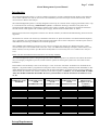
Panel numbers used to identify events are in the range 1 to 255. In the case of Premier AL/Premier AL Global Network
Repeaters , the panel number is programmed via the panel’s menu or the PC Editing software(CAUSE and EFFECT). The
Alarm Manager distinguishes between such panels with the same node address on separate network circuits by adding an
offset based on the network card number as indicated in the following table. ( NODE 16 , 32 , 48 ARE USED AS NODE
AMS NETWORK CARD SEPARATORS. Do not use panel numbers or allocate FACP network addresses to 16,
32, 48)
NODE
ADDRESS/PANEL
NUMBER
CARD 0 / AMS
CARD inside SLOT
of USB
INTERFACE UNIT
CARD 1 / AMS
CARD inside SLOT
of USB
INTERFACE UNIT
CARD 2 / AMS
CARD inside SLOT
of USB
INTERFACE UNIT
1
2
3
4
5
6
7
8
9
10
11
12
13
14
15
1
2
3
4
5
6
7
8
9
10
11
12
13
14
15
17
18
19
20
21
22
23
24
25
26
27
28
29
30
31
33
34
35
36
37
38
39
40
41
42
43
44
45
46
47
Set-up Requirements
CARD 3
Industrial PLC
Computer Unit. Not
Available or
Supported
49
50
51
52
53
54
55
56
57
58
59
60
61
62
63
Page 8 of 108
Alarm Management System Manual
1. Alarm Management set-up disk(s) / ( ALREADY PRE-INSTALLED IN PC TOWER)
2. Hardware as follows:Desktop Computer - minimum requirement
1GHz or above
256MBytes Memory
SVGA 32MByte display adapter (1024 x 768
minimum)
40GByte Hard Disk
Mouse/ Touch screen
QWERTY Keyboard
1 ISA expansion slot or 1 USB 1.1 connector for network
card.
1 parallel port
Monitor
SVGA Colour (1024 x 768 minimum)
Printer
80 Column continuous feed line-printer for event logging.
Page printer for optional map printing.
Software - minimum standard
Windows 2000 or XP Pro.
Page 9 of 108
Alarm Management System Manual
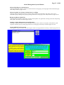
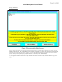
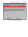
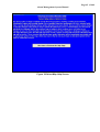
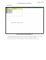
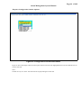
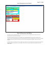
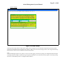
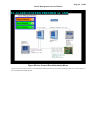
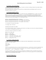
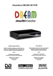
Alarm Manager in Quiescent Condition
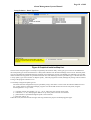
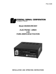
Figure 1 Normal Screen
The screen above is the normal display screen which scrolls the default banner text in quiescent condition.
The banner text can be changed by entering engineer’s code, and selecting configurations from the Utilities menu.
A picture may be displayed in the centre of the screen by copying the required image file (.bmp or .jpg) into the main
Alarm Manager program directory and renaming it as ‘amslogo.bmp’ or ‘amslogo.jpg’ as appropriate.
Page 10 of 108
Alarm Management System Manual
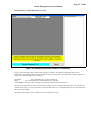
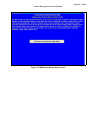
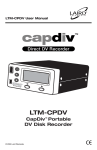
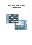
Utilities Menu
The utilities menu can be accessed either from the quiescent screen as described below, or via a command button on the
alarm event display screen.
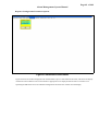
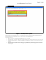
The procedure to access the menu from the quiescent screen is as follows:Double Click with either mouse or touch-screen anywhere on the screen except for where the status message is. This
causes the numeric keypad to be displayed as per Figure 2
Figure 2 Code Entry Keypad.
i)
Enter an appropriate access code either through the on-screen keypad (if it is a numeric code only), or using the
QWERTY keyboard. If a valid access code is entered then a menu will be displayed (as per figure 5) appropriate to the
access level associated with that code, otherwise the keypad will clear and the system will return immediately to normal
operation. Default Access are : 7 or ams. Change password via CREATE AND EDIT USER PASSWORDS
Page 11 of 108
Alarm Management System Manual
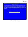
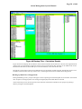
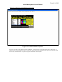
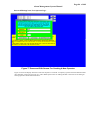
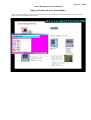
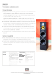
Figure 3 Full Menu Page
i)
From the displayed menu, in which a function is shown , a single click with the mouse or touch screen on the
required box will activate the selected function.
ii)
Upon exit from the menu function, depending upon how long it was active for, and whether or not an alarm
occurred while it was active, one may see the menu again, or the normal default screen, or the display
appropriate to the first alarm that had occurred.
Menu Utilities
Return to Alarm Manager
Selecting the Return to Alarm Manager button will display a normal screen as shown on Figure 1.
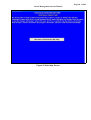
Read Historic log Files
Selecting the historic log files will allow the viewing of previous events. This utility is found on pages 13 to 13.
Group Isolation
Selecting the group isolation files will allow the isolation and de-isolation of sensors on any panel connected to the
computer, both in groups and individually. This utility is found on pages 14 to 21.
Create and Edit Map Pages
Selecting the Create and Edit Map Pages button will allow operator to edit map text, make a new map or view map.
This utility is found on pages 22 to 25.
Edit Text Files for Alarm Sources
Selecting Edit Text Files will allow editing sensor location text, printing text and an information page. This utility is
found on pages 26 to 33
Page 12 of 108
Alarm Management System Manual
Allocate Map Pages to Alarm Sources
Selecting Map Pages will allow operator to allocate sensors to map pages, print map pages and an information page.
This utility is found on pages 34o 41
Allocate Symbols for Groups of Alarm Sources on Maps
Selecting Allocate Symbols for Groups will allow alarm symbols to be allocated to map pages, sensors to be
allocated to groups, editing sensor groups, printing and access to a help page. This utility is found on pages 42o 56
Backup and Restore Disk Files
Selecting Backup and Restore Disk Files will allow back up disks to be generated, restoring system files and printing
back up files. This utility is found on pages 56o 59
Configure Alarm Management System Responses
Selecting Configuration files will allow setting up of network cards, controls on computer, sound, Banner, panel
responses, isolation groups, printing page and access to a help page. This utility is found on pages 59 to 82.
Create and Edit User Passwords
Selecting the User password files will allow engineer codes to be programmed. This utility is found on page 83 to 86.
Page 13 of 108
Alarm Management System Manual
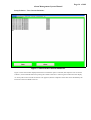
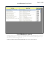
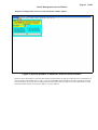
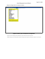
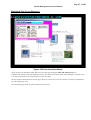
Read Historic Log.
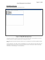
Figure 4 Read Historic Log.
Figure 4 shows the historic log reading screen with its list of the most recent events. The scroll bar allows for viewing
further events that are off the edge of the screen, and the menu items allow for printing recent events over various time
periods, for adjusting the display font size, and for returning to the Alarm Manager. The column widths may be
adjusted by dragging the dividing lines in the header area to allow more or less text to be visible in each column.
Page 14 of 108
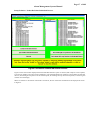
Alarm Management System Manual
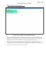
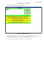
Group Isolation.
Figure 5 Group Isolation Main Screen.
Figure 5 shows the initial screen when the Group Isolation function is selected. This comprises a list of the currently
defined isolation groups, with command buttons for isolating, de-isolating, or viewing the contents of a selected group,
and menu options for listing all current isolations, carrying out individual isolations, returning to the list of isolation
groups, viewing a list of panel types, graphical isolation, or returning to the Alarm Manager.
n.b. The graphical isolation menu item is only available if the there is at least one map with the characters ‘[I]’ in its
name.
Page 15 of 108
Alarm Management System Manual
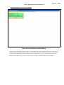
Group Isolation - Isolate/De-Isolate a Group.
Figure 6 Sending Isolation/De-Isolation Commands.
Figure 6 shows the display that is shown when a group is isolated or de-isolated, and identifies the series of
commands to be transmitted to the network together with the state of progress. The right hand column of the list can
indicate one of the following status messages:WAITING
SENT
CONFIRMED
The command has not yet been transmitted.
The command has been transmitted but not confirmed.
Receipt of the command by the appropriate panel has been confirmed.
The list on the right shows the actual confirmation messages received. A panel such as the Nexus will not isolate all
possible sensor types, so it may not isolate all of the selected sensors. Its confirmation messages will only identify the
devices actually isolated.
The Cancel button allows for this window to be removed from the screen.
Page 16 of 108
Alarm Management System Manual
Group Isolation - View Current Isolations.
Figure 7 View List Of Current Isolations.
Figure 7 shows the window displayed when the List Isolations option is selected, and comprises a list of current
isolations, with command buttons for printing the contents of the list or removing this window from the display.
n.b. It may take several seconds for the list to be prepared, but the completion of the task can be identified by the
inclusion of the word 'END' to the list.
Page 17 of 108
Alarm Management System Manual
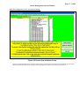
Group Isolation - Isolate/De-Isolate Individual Devices.
Figure 8 Isolate/De-Isolate Individual Devices.
Figure 8 shows the window displayed when the Individual Isolation option is selected, and comprises a list of panels,
a list of loop numbers, and a list of sensor addresses, with command buttons for isolating or de-isolating the selected
devices, de-isolating all loop devices at the selected panel, de-isolating all loop devices at all panels, or removing this
window from the display.
When an isolation or de-isolation command is carried out, the list of network commands will be displayed as shown
in Figure 6.
Page 18 of 108
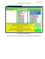
Alarm Management System Manual
Group Isolation – Panel Type List.
Figure 9 Graphical Isolation Map List.
This list shows the panel types as currently recognised by the isolation utility. If the types given in this list are different to
the actual panel types on the network then it is likely that isolations from the Alarm Manager will not work. Normally these
types are automatically established from the messages received from the network. The default type indicated is the type that
will be assumed for any panels not specified in the main list. This default type will be specified as type 11 Premier AL 1/2or
1/4 loop panel ( type 10 for Premier AL Repeter panel) , when the program first loads, although any change will be retained
as long as the program continues to run.
To manually configure the panel type list:
The actual network configuration may be specified by using a text editor to create a text file called ‘PANELS.TXT’ in
the ‘config’ directory of the alarm manager program. This file should contain one line for each panel, using the
following format: ‘cn=p,t’ where
c = computer network card number (‘0’-‘3’) – use ‘0’ where only one network card is used.
n = node letter (‘A’-‘O’) identifying the address set up on the panel’s network card switches.
p = panel number as specified through the panel’s network menu.
t = panel type code (1-11).
If this file exists, then the network messages will be ignored for the purpose of identifying panel types.
Page 19 of 108
Alarm Management System Manual
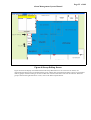
Group Isolation – Graphical Isolation.
Figure 10 Graphical Isolation Map List.
Figure 10 shows the window displayed when the Graphical Isolation option is selected, and comprises a list of maps
that are allocated to this function. The ‘Quit’ menu item returns to the main Group Isolation page, while selecting a
map from the list will display the map with its symbols as shown in Figure 11.
Page 20 of 108
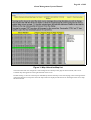
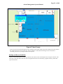
Alarm Management System Manual
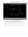
Figure 11 Graphical Isolation Map Display.
Sensor symbols are shown as either plain red squares (de-isolated) or yellow squares containing a cross (isolated).
Currently selected symbols are identified by a purple circle, as indicated in the above picture.
The bar at the bottom of the screen will show the address details for a symbol as the mouse pointer moves over it.
Menu items are provided to either isolate or de-isolate the selected devices, and to return to the map list shown in
Figure 10.
When an isolation or de-isolation command is carried out, the list of network commands will be displayed as shown
in Figure 6.
Page 21 of 108
Alarm Management System Manual
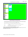
Group Isolation - View Contents Of Group.
Figure 12 View Contents Of Group.
Figure 12 shows the window displayed when the View Contents Of Group option is selected for a specific group, and
comprises a list of the devices allocated to the specified group, with a command button for removing this window
from the display.
Page 22 of 108
Alarm Management System Manual
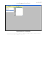
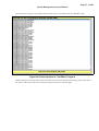
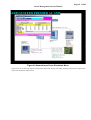
Edit Map/Procedure Pages
Figure 13 shows the opening screen of the Map Edit Utility.
Figure 13 Map Edit Opening Screen
The opening screen has a menu bar across the top and a list of existing map names. Any maps that have not yet been
allocated real names will simply be identified by the word Map plus its number.
Note: The maps whose name includes the characters ‘[I]’ are intended to be used for the graphical isolation
facility.
The menu functions "View Map", "Edit" and "Edit Map Text" are only valid if one of the maps in the list is
highlighted and that will be the map on which the function will work. The functions "Make a New Map"
and "Return to Alarm Manager" are self-explanatory.
Page 23 of 108
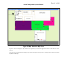
Alarm Management System Manual
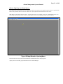
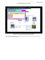
Figure 14 Viewing Map Number 1
Select a map in the list then select "View Map" the selected map will be shown as shown in Figure 14.
To remove this map from the display just click anywhere on the map itself.
The 'View' menu also allows procedure pages to be viewed.
Page 24 of 108
Alarm Management System Manual
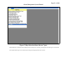
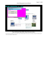
Figure 15 Microsoft Paint Loaded to Edit an Existing Map
Select a map, then select "Edit Map”. The appropriate bitmap editor will be loaded with the selected map page, ready
for editing as shown in Figure 15.
n.b. Alternative bitmap editors may be specified throught the 'Edit' menu.
Please refer to the manual for the selected bitmap editor for instructions on how to edit the bitmap.
Page 25 of 108
Alarm Management System Manual
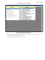
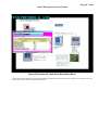
Figure 16 Editing a Map Name Text
Figure 16 shows the text editing window that is displayed when "Edit Text" menu function is activated. This window
is cleared when the ENTER key on the QWERTY Keyboard is pressed, at which time the text as shown in the editing
window will replace the original text in the main list.
If the map will contain symbols that need to be accessable for graphical isolation then the characters ‘[I]’ should be
included in the name.
The text in the list will be saved back to disk when the "Return to Alarm Manager" function is activated.
Activation of the "Make New Map" menu function causes the selected bitmap editor to be loaded with a blank map
image. For computers with higher screen resolutions a choice of map sizes will be offered, defaulting to the largest size
appropriate to the screen area.
Page 26 of 108
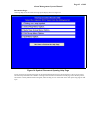
Alarm Management System Manual
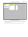
Edit Message Texts
Figure 17 Opening Screen of Text Editor
The white bar at the top of the screen is a menu bar, and the four text items displayed are the available menu options.
Page 27 of 108
Alarm Management System Manual
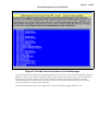
Information
This item when selected causes the first of two information pages to be displayed, and at the bottom of that page are
two command buttons. One button is for moving on to the second information page, while the other is for leaving the
information page and returning to the original menu page.
The second information page likewise has two command buttons at the bottom of it, one for going back to the first
information page, and the other for going back to the menu page. These two information screens are shown in Figure
18 and Figure 19.
Figure 18 First Information Page of Text Editor
Page 28 of 108
Alarm Management System Manual
Figure 19 Second Information Page of Text Editor
Page 29 of 108
Alarm Management System Manual
Edit Files
When this option is selected, the menu items along the top of the screen are disabled, and a list of possible file types
is shown, together with the option to finish editing.
Figure 20 File Options for Text Edit
Double-clicking on one of above file types causes a list of possible nodes to be displayed. In the case of sensor/point
text, double-clicking on the node list will cause a list of possible loop numbers to be displayed, while for the other
message types, the edit screen is displayed. Double-clicking on the loop list will then bring up the edit screen for
editing sensor texts for that loop of the selected node.
The next page of this document shows the two display stages for selecting a sensor/point loop, while the following
page shows the actual edit screen itself.
Page 30 of 108
Alarm Management System Manual
Figure 21 Node List of Text Editor
If sensor/point texts are selected for editing, then the display shown in Figure 21 appears so that the required panel
can be selected by clicking on the appropriate entry in the list.
Page 31 of 108
Alarm Management System Manual
Figure 22 Loop List of Text Editor
Panel 2 has been selected for editing Premier AL point texts, so now we are prompted to select the required loop
within panel 2. Click on the appropriate entry in the loop list, if necessary using the scroll bar to access loop numbers
not immediately visible in the list.
n.b. In this instance only loops 1 to 4 are applicable since a Premier AL panel can only have up to 4 loops.
Page 32 of 108
Alarm Management System Manual
Figure 23 Text edit Screen for Premier AL Point Messages
Figure 23 shows the text editing screen for editing Premier AL point texts for loop 1 of node 1, although the general
appearance of this screen is the same whichever function type is selected. The number of texts in the list depends on
the function type, and the yellow bar near the top of the screen identifies the exact file that has been selected.
Generally there will be 255 node names, 126 sensors/points per loop, 128/255 network inputs per node, and 255
circuits for each R3 circuit type (Zones, Inputs etc.).
The instructions at the top of the screen explain how to select a text item for editing, and how to edit.
Page 33 of 108
Alarm Management System Manual
Figure 24 shows a typical screen display when the Print option is selected from the Text Edit Menu Bar:-
Figure 24 Printer Options in Text Editor Program
Double-clicking on one of the above items causes that list of text to be printed, while clicking on the yellow box at
the bottom of the screen clears this list from the display and returns to the menu page.
Page 34 of 108
Alarm Management System Manual
Allocate Map Pages to Alarm Sources
This function is used to specify up to five maps/procedures to be shown when a particular alarm source is operated into
alarm. This operation must be carried out before the symbol placement described in the next section.
N.B. Maps are allocated to Alarm Sources, not individual events. For example, in the case of addressable sensors, the
same maps will be shown for Fire, Alert or Fault, only the colour of any flashing symbols will be different.
Figure 25 Map Allocation Opening Menu
The menu bar at the top of the screen identifies the available functions in this program:"Quit" just exits from this program and returns to the Alarm Manager.
Page 35 of 108
Alarm Management System Manual
Figure 26 Map Allocation Information Page
Figure 26 shows the information page displayed when the Information item on the menu bar is clicked. Click on Exit
Information to clear this page from the display.
Page 36 of 108
Alarm Management System Manual
Figure 27 Map Allocation Alarm Source Types
When Edit Files is selected, then the display shown in Figure 27 is shown, prompting for the alarm type to be selected.
The required alarm type can be selected by clicking on the appropriate item in the list.
Page 37 of 108
Alarm Management System Manual
Figure 28 Map Allocation Node List
The panel list shown in Figure 28 will appear whichever alarm type is selected, although in this example it is the
Premier AL Sensor Map Pages which has been selected.
Click on the appropriate panel item to select a panel for editing.
Page 38 of 108
Alarm Management System Manual
Figure 29 Map Allocation Loop List
The display in Figure 29 shows that Panel 1 has been selected for Premier AL Sensor Map Page editing, so the list of
loop numbers now prompts for the selection of the required loop. The scroll bar at the right hand edge of the loop list
allows other loop numbers to be brought into view.
Clicking on a valid loop number will bring up the Map Page editing screen as shown in Figure 30.
Page 39 of 108
Alarm Management System Manual
Figure 30 Map Allocation Circuit List
Figure 30 shows the display for editing the Map Page allocation for sensors on panel 3 loop 4. The instructions at the
top of the screen describe the editing procedure, while the table below the instructions lists the pages currently
allocated to the sensors on this loop. The scroll bar at the right hand edge of the table allows other sensors to be
brought into view.
In this example, clicking on the Page 1 box for sensor number 3 results in the display shown in Figure 31.
Page 40 of 108
Alarm Management System Manual
Figure 31 Map Allocation Map List
The selected box has now changed to a white background to identify which page has been selected, and a list of
available maps has appeared on the right hand side of the screen.
Double-clicking on an item in the map list immediately allocates that map to the selected page, while clicking with the
right mouse button on a map item causes the map itself to be displayed. This allows for checking that the correct map
has been selected.
Page 41 of 108
Alarm Management System Manual
Figure 32 Map Allocation Map View
Figure 32 shows the display of Map number 4 as requested by a click of the right mouse button on the fifth line of the
map list.
This map may be cleared from the display to get back to the display of Figure 31 by clicking with the left mouse button
anywhere on the map.
Page 42 of 108
Alarm Management System Manual
Place Symbols on Maps
Selecting this option from the main Alarm Manager menu produces the display shown in Figure 33.
Figure 33 Symbol Placement Opening Menu
The menu options available here are Select Map, Help or Quit. Clicking on any of these selects the appropriate
function.
Page 43 of 108
Alarm Management System Manual
Information Pages.
Selecting 'Help' from the menu bar brings up the display shown in Figure 34.
Figure 34 Symbol Placement Opening Help Page
Figure 34 shows the opening help menu in the Symbol Placement Program, and prompts for a choice of five topics
for which help information is available. Clicking on the Exit button at the bottom of the page clears the help screen,
and returns to the Symbol Placement Program, while clicking on one of the other items calls up the help page for that
topic.
Page 44 of 108
Alarm Management System Manual
Figure 35 Map Click Help Screen
Page 45 of 108
Alarm Management System Manual
Figure 36 Select Map Help Screen
Page 46 of 108
Alarm Management System Manual
Figure 37 Make New Group Help Screen
Page 47 of 108
Alarm Management System Manual
Figure 38 Edit Group Help Screen
Page 48 of 108
Alarm Management System Manual
Figure 39 Quit Help Screen
Page 49 of 108
Alarm Management System Manual
Edit Options.
Figure 40 Symbol Placement Map List
Clicking on the Select Map item on the menu bar causes a list of available maps to be displayed as shown in Figure
40. Double-clicking on one of these map names in the list box allows that map to be worked on.
Figure 41 shows Map number 3 chosen, assuming that no symbols have already been placed on this map.
Page 50 of 108
Alarm Management System Manual
Figure 41 Symbol Placement Map Menu
Since the menu item Make New Group is enabled (i.e. shown in black text) this implies that there are some alarm
sources that have been allocated to this map, but not to a symbol on the map. If some symbols had already been
placed on this map then they would be shown in the appropriate locations on the map.
Clicking on the Make New Group function causes a display such as that in Figure 42 to be shown.
Page 51 of 108
Alarm Management System Manual
Figure 42 Make New Group Option
Selecting Make New Group causes two lists to appear as shown in Figure 42, together with a button labelled Copy
Selection.
The left hand list details the alarm sources that are allocated to this map but not tied to a symbol, while the right hand
list is initially blank, but will list the alarm sources for the new group.
Alarm sources in the left hand list may be selected for the new group by clicking on them, and when the highlighted
alarm sources are correct, then clicking on the Copy Selection button will transfer the selected items into the right
hand list. This will result in a display similar to the example shown in Figure 43.
Page 52 of 108
Alarm Management System Manual
Figure 43 Ready to Place New Symbol
Figure 43 depicts the display when one sensor in loop 2 of Panel 12 have been selected for a new group. Clicking on
the Place Symbol button clears the two list boxes from the display, and shows a new symbol that may be moved to an
appropriate location on the map.
N.B. the symbol will initially appear at the top left corner of the map, and will move around the map in response to
the mouse. Clicking the left mouse button when the symbol is in the desired location will place the symbol at that
point.
Page 53 of 108
Alarm Management System Manual
Figure 44 New Individual Symbol Placed on the Map
Figure 44 shows the new individual symbol (an individual symbol because it has only one alarm source associated with it)
placed in the appropriate area of the map.
Page 54 of 108
Alarm Management System Manual
Figure 45 Viewing The Alarm Sources Associated with a Symbol.
Clicking on the new symbol (or any other existing symbols) on the map results in a list appearing identifying the
alarm sources associated with that symbol, as shown in Figure 45. This also enables the menu function Edit Group so
that the list of alarm sources associated with this symbol may be edited. Clicking on the menu function Edit Group
from here will result in the display shown in Figure 46.
Page 55 of 108
Alarm Management System Manual
Figure 46 Group Editing Screen
Figure 46 shows the display associated with the Edit Group Menu function. Two list boxes are shown, one
representing the alarm source associated with the group, and the other representing the alarm sources not associated
with any groups. Double-clicking on an item in either list will move that item across into the other list. When the
group as listed in the right hand list is correct, click on the Edit Complete button.
Page 56 of 108
Alarm Management System Manual
Figure 47 Save Prompt
Figure 47 shows the prompt that appears when clicking on either Select Map or Quit after changes have been made to
the symbol allocation on the current map. If the Yes button is clicked, then the changes will be saved before
continuing, otherwise any changes made will be forgotten.
Backup and Restore Disk Files
Selection of the Backup/Restore Disk Files from the main menu results in the display shown in Figure 48 below. The
three lists on the left of the screen show the existing data files that can be backed up, together with the posible disk
types and locations.
Page 57 of 108
Alarm Management System Manual
Figure 48 Backup Files Opening Screen
The type of backup media to be used should be selected from the Disk Type list, and the drive letter associated with it
should be selected from the Disk Drive list. The Special option is intended for use when either a ZIP disk, Memory
stick, or a hard disk is to be used for backing up where at least 64MB is available.
The menu options at the top of the screen that are immediately available are as follows:Disks?
Restore
Exit
- calculates how many backup disks of specified type are needed, and allocates files to
each disk.
- allows for copying files from the backup disks back on to the hard disk.
- returns to the Alarm Management Program.
Warning : 64MB Limit can easily be achieved , as .bmp Map files are large files.
To Back Up , go into Windows explorer, or My computer in the PC., And copy the AMSGLTU2 Folder, to a Back
up or Temp Folder before making any amendments to the AMS, system.
Back up folders at least once a week.
Calculate the Number of Disks Needed for Backup
Page 58 of 108
Alarm Management System Manual
Figure 49 Backup Files - Calculation Results
Figure 49 shows the display after the Disks? item has been selected from the menu bar. The list at the right hand side
of the screen gives the number of bytes that will be stored on each backup disk, while the list in middle of the screen
identifies the files that will be backed up on to the selected disk, in this case the first disk.
The blue box at the bottom of the screen identifies the type and number of disks required. The Backup option is now
available on the menu bar at the top of the screen, so selecting this function will initiate the backup process.
Backing Up Data Files to Floppy Disks
During the Backup process, prompts will appear in turn requesting for each backup disk to be inserted in the selected
drive if required, with appropriate error messages being displayed if invalid disks are inserted.
At the end of this process, the Print option on the menu bar will become available, for the purpose of printing a
directory listing for each backup disk.
Page 59 of 108
Alarm Management System Manual
Restoring Files from the Backup Disks
When this option is selected from the menu bar, a prompt first appears asking how many backup disks are to be
restored. Once this has been specified, then a series of prompts appear for each disk from one to the number
specified, for the appropriate disk to be inserted into the selected drive.
When the process is complete, the prompt boxes will be cleared just leaving the menu screen as in Figure 48 above.
Printing Directory Lists for Backup Disks
This option only becomes available when the backup process is complete, and selecting it will result in a printout that
lists the files that have been copied onto each backup disk. Before selecting this option it is essential to ensure that a
printer is available and on-line.
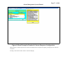
Configure System Responses
Figure 50 Configuration Opening Menu
Clicking on the Exit option returns to the main Alarm Manager Program.
Page 60 of 108
Alarm Management System Manual
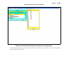
Response Configuration Help.
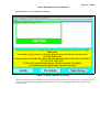
Figure 51 Response Configuration Help Page
Figure 51 shows the help page displayed when the Help option is chosen from the menu bar of the Response
Configuration Program. This page summarises the default responses for each type of alarm message. Clicking on Exit
clears this page from the display.
Page 61 of 108
Alarm Management System Manual
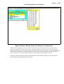
Response Configuration Network Cards and Panel Number Option.
Figure 52 Specify Number Of Network Cards and Panel Number.
Figure 52 shows the display to select the panel number and the number of network cards fitted, up to a maximum of 4
network cards in internal ISA slots, or up to 3 in an external USB interface motherboard. With 15 nodes per network
card, a maximum of 60 nodes can be configured when internal ISA cards are used, or 45 if the USB interface is used.
The panel number may be 0 (if a passive node) or 1 to 255 otherwise.
Page 62 of 108
Alarm Management System Manual
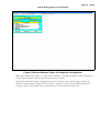
Response Configuration Controls Options.
Response Configuration Command Buttons Options.
Figure 53 User Control Command Button Options.
Figure 53 shows the display when the Controls – Silence Alarms option has been selected. The three check boxes
identify whether or not the Alarm Management Program will allow the Silence Alarms button to be displayed when a
fire event is received, and if so when it will clear from the screen. Similar option settings may be defined for Reset
System and Clear Display. The selected options will be saved to disk when the program is exited.
N.B. This only affects the display of the appropriate buttons on the computer screen at the appropriate time, and
consequently the transmission of suitable messages on to the network. It does not imply that any of the panels
connected to the network will respond to those messages. That depends upon the respective panel's own configuration.
Clicking on the OK button clears this prompt box from the display.
Page 63 of 108
Alarm Management System Manual
Response Configuration Cancel Mode Options.
Figure 54 Cancel Button Option Editing.
Figure 54 shows the display when the Controls - Cancel Mode option has been selected. The three check boxes
identify when the Alarm Management Program will allow the display to be cleared following a fire event. It may be
required to wait until the appropriate panels have been reset before allowing the computer display to be cleared.
Clicking on the OK button clears this prompt box from the display, and sets the indicated Cancel Mode.
Page 64 of 108
Alarm Management System Manual
Response Configuration Sounder Options.
Figure 55 Configuration Sound Select Menu
Figure 55 shows the display when the sound option has been selected. The highlighted item in the list identifies that no
sound is selected.
Note:Sounds can only be ‘.WAV’ files that need to be played though a sound card.
Page 65 of 108
Alarm Management System Manual
Response Configuration Banner Options.
Response Configuration Normal Banner Specification.
Figure 56 Normal Banner Options
Figure 56 shows the prompt displayed when the Banner - Normal option is selected from the menu. This display shows
the actual appearance of the banner at the top, with lists and selection boxes below for selecting a font name and size,
the colour for the text, and the actual text itself. Editing any of these attributes will immediately update the text shown
in the top of the window, but the details stored on disk for the main banner will not be updated until the OK button is
operated. The Cancel button allows this window to be removed from the display without saving any changes.
Page 66 of 108
Alarm Management System Manual
Response Configuration Isolated Banner Specification.
Figure 57 Isolation Banner Options
Figure 57 shows the prompt displayed when the Banner - Isolated option is selected from the menu. This display is
similar to that shown in Figure 56 above, but operates on the banner that is displayed under quiescent conditions when
there are any isolated sensors or inputs at any panel connected to the computer.
Page 67 of 108
Alarm Management System Manual
Response Configuration Printer Offline Banner Specification.
Figure 58 Printer Offline Banner Options
Figure 58 shows the prompt displayed when the Banner - Printer Offline option is selected from the menu. This display
is similar to that shown in Figure 56 above, but operates on the banner that is displayed under quiescent conditions
when the printer is off-line.
Page 68 of 108
Alarm Management System Manual
Response Configuration Isolated And Printer Offline Banner Specification.
Figure 59 Isolation & Printer Offline Banner Options
Figure 59 shows the prompt displayed when the Banner - Isolated option is selected from the menu. This display is
similar to that shown in Figure 56 above, but operates on the banner that is displayed under quiescent conditions when
there are any isolated sensors or inputs at any panel connected to the computer, and the printer is off-line.
Page 69 of 108
Alarm Management System Manual
Response Configuration Parameter Options.
Figure 60 Parameters Select Menu
Figure 60 shows the window displayed when the Parameters option is selected from the menu, and allows the display
of either the sensor address or the circuit number as appropriate to be displayed with the text for an alarm event.
Operating the OK button stores the indicated configuration and clears this window from the display.
Page 70 of 108
Alarm Management System Manual
Response Configuration Event Response Options.
Figure 61 Alarm Types for Response Configuration
Figure 61 shows the display after the Responses item has been selected from the menu.
Double-clicking on the selected alarm type allows editing of the responses for that type of alarm to be carried out.
Page 71 of 108
Alarm Management System Manual
Figure 62 Panel Prompt for Premier AL Sensor Response Configuration
When Premier AL Points responses are chosen, the display shown in Figure 62 appears, prompting for the selection
of a panel.
Clicking on the Cancel button returns to the menu display.
Page 72 of 108
Alarm Management System Manual
Figure 63 Loop Number Prompt for Response Configuration
Double-clicking on the Panel 1 entry from Figure 62 results in the display shown in Figure 63. This is now prompting
for the selection of a loop number.
Page 73 of 108
Alarm Management System Manual
Figure 64 Sensor Number Prompt for Response Configuration
Figure 64 shows the display once loop 1 of panel 1 has been selected. The required sensor(s) on that loop now
need(s) to be identified. A range of sensors can be selected by clicking on the first sensor in the range, and then
holding down the shift key on the keyboard whilst clicking on the last sensor in the range. Clicking on the OK button
will then allow the allocation of a response pattern for all of the sensors in that range. Clicking on the All button
selects all 126 sensors, but the OK button still needs to be operated before allocating the responses.
Clicking on the Cancel button returns to the main menu, while double-clicking on a sensor in the list
allows response allocation for that sensor alone.
Page 74 of 108
Alarm Management System Manual
Figure 65 Sensor Message Types for Response Configuration
When either a single sensor address, or a range of sensor addresses, is selected, the display is as shown in Figure 65.
In this example all sensors 1-126 have been selected on loop 1 of panel 1.
The list shown identifies the types of message that can be received from a sensor, and selecting one of these by
clicking on it then produces a display as shown in figure 56. Clicking on one of the command buttons allows for
moving on, either to select another sensor, or another loop, or to return to the main menu screen.
Page 75 of 108
Alarm Management System Manual
Figure 66 Response Code Editing
The red box shown at the bottom of the screen in Figure 66 shows the available response options that can be
specified for the selected alarm message(s).
The printer and log file, both shown here enabled, may be enabled/disabled as appropriate by clicking on the
respective boxes. The required display option may be selected by clicking on the appropriate item in the list. Clicking
on the Save button will clear this box from the screen, and save the appropriate response codes for the sensors
selected.
N.B. The sequence is basically the same for other types of alarm source, with appropriate message types being listed.
Some alarm types only prompt for a panel number, while others will require both a panel number and a circuit
number/range.
Page 76 of 108
Alarm Management System Manual
Response Configuration Isolation Group Definition.
Figure 67 Isolation Group List
Figure 67 shows the display presented when the Isolation Groups option is selected from the menu.
This display basically comprises a list of the currently defined isolation groups, with command buttons for creating a
new group, editing an existing group, removing a group, or finishing with this function.
A group in the list must be selected by clicking on it before it can be edited or removed.
Page 77 of 108
Alarm Management System Manual
Response Configuration Create New Isolation Group.
Figure 68 Create New Isolation Group.
Figure 68 is displayed after the Create New Isolation Group option has been selected, and a name for the new group
has been entered. The instruction prompts shown identify how to add or remove devices from the list.
Page 78 of 108
Alarm Management System Manual
Response Configuration Edit Isolation Group.
Figure 69 Edit Isolation Group.
Figure 69 is displayed after the Edit Isolation Group option has been selected with the first group highlighted in the
list shown in Figure 67. The instruction prompts shown identify how to add or remove devices from the list.
Page 79 of 108
Alarm Management System Manual
Printer Options.
Figure 70 Printout Configuration Settings.
This menu allow for either printing out the configuration details, identifying and configuring the printers, or configuring the
auto-map-printing facility.
Page 80 of 108
Alarm Management System Manual
Printout Configuration Settings.
Figure 71 Printout Configuration Settings.
Selecting Printer:Configuration Printouts brings up the display shown in Figure 71, from which the required printout may
be selected by clicking on the appropriate button. Click on ‘Quit’ when finished.
Page 81 of 108
Alarm Management System Manual
Printer Settings.
Figure 72 Printer Setup.
Selecting Printer:Setup Printer brings up the display shown in Figure 72, from which the required line-printout type and
port may be selected from the drop-down lists. Click on ‘OK’ to save the chosen settings and exit. The ‘Page Printer Setup’
button may be used to access the Windows Printer Setup facility.
Note:
The Alarm Manager supports two printers, one just for event logging, and one for printing out configuration data and maps.
The display shown in Figure 72 allows the type of printer and the port to be selected for the line-printer. The other printing
functions use the default printer as configured under Windows.
Page 82 of 108
Alarm Management System Manual
Auto Map Printing.
Figure 73 Auto Map Printout Options.
Selecting Printer:Auto Map Printing brings up the display shown in Figure 73, from which the required automatic map
printing mode from the drop-down list. Click on ‘OK’ to save the chosen setting and exit.
The possible modes are
1. None – no maps are printed automatically when a fire event is reported.
2. First Page Only – the first map page only is printed on the page printer automatically when a fire event is reported.
3. All Pages in Normal Sequence – all associated pages are printed, starting with page 1, in turn when a fire event is
reported.
4. Last Page Only – the last map page only is printed on the page printer automatically when a fire event is reported.
5. All Pages in Reverse Sequence – all associated pages are printed, starting with the last page, in turn when a fire
event is reported.
Page 83 of 108
Alarm Management System Manual
Edit Operator/Password List
Figure 74 Opening Screen of Password Editor
The display shown in Figure 74 contains a list of current operators with their respective access levels, together with an
instruction prompt, and command buttons to Quit, Edit or Add a new operator. Note that the only Level 7 operator in
the list is the Manager. In this case the Manager is the only operator with that access level, but if there were others they
would not be shown. This allows the person accessing this program to alter their own password , and those of
operators with lower access levels, but not those of any other operators with the same access level.
Operating the Quit button on the main screen returns to the Alarm Management Program.
Page 84 of 108
Alarm Management System Manual
Password Editing Help Page.
Figure 75 Password Editor Help Screen
Figure 75 shows the Help screen displayed when the Help button is operated. This page of information defines the 6
different access levels available, and the limitations of each level. Each successive level can access all of the facilities
of the lower levels, as well as the additional facility mentioned.
Clicking on the Exit Help Page button clears this page from the screen and returns to the main Password Editor
Screen.
If the main menu was entered with an access level 6 or 7 password, then the menu option for editing the list of
operators and passwords is shown, and selecting this option gives a display similar to the example shown in Figure
74.
Page 85 of 108
Alarm Management System Manual
Password Editing Edit Operator Details Page.
Figure 76 Password Edit Screen For Existing Operator
Figure 76 shows the display when operator 3 (Security Controller) is selected by clicking on the list of operators.
Clicking on either the Operator's Name, Password or Access Level boxes allows that item to be edited. The three
buttons at the bottom of the edit window are self-explanatory:- The Remove Operator button clears the Edit window
and removes the selected operator from the main list; the Save Changes button clears the edit window and updates
the main list with the details entered; the Quit without Saving button just clears the Edit window but leaves the main
list as it was.
Page 86 of 108
Alarm Management System Manual
Password EditingCreate New Operator Page.
Figure 77 Password Edit Screen For Creating A New Operator
Figure 77 shows the display when the Create New Operator is selected. A temporary operator has been defined called
'New Operator', with an access level of 1, and a default password of '0'. Editing the data is the same as for editing an
existing operator's details described above.
Page 87 of 108
Alarm Management System Manual
Simulated Fire Event Response.
Figure 78 Event Simulation Menu.
Figure 78 shows the Simulation Menu that may be accessed by pressing the 'Shift' and 'Function 12' keys
simultaneously from the main Alarm Manager Screen. This allows the response of the Alarm Manager to specific events
to be observed without the need to generate real events at a panel.
The test sequence described in the next few pages involves a sensor Fire event, but a similar process may be adopted for
any other appropriate event.
The subsequent pages show the other simulation option screens.
Page 88 of 108
Alarm Management System Manual
Figure 79 Premier AL Sensor Event Simulation Menu.
Figure 79 shows the Premier AL Sensor Event Simulation Menu that may be accessed by clicking on the Premier AL
Sensor option on the main Simulation Menu Screen.
In order to simulate a sensor event it is necessary to select a panel number from the list at the top, an event type, a point
type, a loop number, and a sensor address. A user text may also by typed into the lower box if required. Once the
necessary items have been selected, clicking on the upper command button will remove this window from the screen and
initiate an appropriate response from the Alarm Manager as if the specified event was received from the network.
The lower command button clears this window from the display without generating any events.
Page 89 of 108
Alarm Management System Manual
Figure 80 Sensor Event Simulation - Accept Prompt.
Figure 80 shows the initial event response screen for a Premier AL Dual Sensor fire event on panel 7 Premier AL HOTEL,
loop 1 , device 3. If a Call point option is configured then this display will be accompanied by the corresponding sound.
The displayed map is the first page allocated to the device in alarm.
The red box with two lines of text identifies the event details:Line 1 gives the panel, loop and sensor numbers (which may be turned off through the Parameter configuration option),
the name of the source panel (in this case 'TECH DEMO LAB’), the event type, and the supplied user text enclosed in
square brackets.
Line 2 just displays the user text associated with the device in alarm as stored on the computer.
The symbol, if there is one, will be flashing.
Page 90 of 108
Alarm Management System Manual
Figure 81 Sensor Event Simulation - Map Page 1.
Figure 81 shows the event response screen following the operation of the accept button on Figure 80. At this stage the
sound will have stopped.
The displayed map is the first page allocated to the device in alarm, as indicated by the depressed page button.
The optional 'Silence Alarms', 'Reset' and 'Clear Display' buttons (as enabled/disabled though the Controls response menu)
are displayed in place of the 'Cancel' button shown. The 'Cancel' button is always the last to be shown here, and is used to
clear the alarm event display from the screen.
The table below summarises this heirarchy:EVENT
SILENCE ALARMS
RESET
CLEAR DISPLAY
DISPLAYED
ENABLED
ENABLED
ENABLED
BUTTON
Fire
Yes
SILENCE ALARMS
Fire
No
Yes
RESET
Fire
No
No
CANCEL
Fire and Silence Alarms
Yes
RESET
Fire and Silence Alarms
No
CANCEL
Fire, Silence Alarms and
CANCEL
Reset
Non-Fire
Yes
CLEAR DISPLAY
Non-Fire
No
CANCEL
Non-Fire and Clear
CANCEL
Display
Page 91 of 108
Alarm Management System Manual
Figure 82 Sensor Event Simulation - Map Page 2.
Figure 82 shows the event response screen following the operation of the page 2 button on Figure 81.
The displayed map is the second page allocated to the device in alarm, as indicated by the depressed page button.
n.b. although this device has two map pages associated with it, any number from one to five pages may be allocated, and
the number of buttons will be adjusted to suit.
Page 92 of 108
Alarm Management System Manual
Figure 83 Sensor Event Simulation - Procedure Page.
Figure 83 shows the event response screen following the operation of the procedure button on Figure 81, Figure 82, or
Figure 84.
The displayed page is that allocated to alarm priority 7 (Fire). Alternative pages are available for priority levels 6, 5, 4, 3.
Page 93 of 108
Alarm Management System Manual
Figure 84 Sensor Event Simulation - Events Page.
Figure 84 shows the event response screen following the operation of the events button on Figure 81, Figure 82, or Figure
83.
Page 94 of 108
Alarm Management System Manual
Figure 85 User Control Event Simulation Menu.
Figure 85 shows the User Control Event Simulation Menu that may be accessed by clicking on the User Control option on
the main Simulation Menu Screen.
Page 95 of 108
Alarm Management System Manual
Figure 86 Network Input Event Simulation Menu.
Figure 86 shows the Network Input Event Simulation Menu that may be accessed by clicking on the Network Input option
on the main Simulation Menu Screen.
Page 96 of 108
Alarm Management System Manual
Figure 87 Common Fault Event Simulation Menu.
Figure 87 shows the Common Fault Event Simulation Menu that may be accessed by clicking on the Common Fault
option on the main Simulation Menu Screen.
Page 97 of 108
Alarm Management System Manual
Figure 88 Node Online/Offline Event Simulation Menu.
Figure 88 shows the Node On-line/Off-line Event Simulation Menu that may be accessed by clicking on the Node option
on the main Simulation Menu Screen.
Page 98 of 108
Alarm Management System Manual
Figure 89 Premier AL Fault Event Simulation Menu.
Figure 89 shows the Premier AL Fault Event Simulation Menu that may be accessed by clicking on the Premier AL Fault
Event option on the main Simulation Menu Screen.
Page 99 of 108
Alarm Management System Manual
Figure 90 Premier AL User Control Menu.
Figure 89 shows the Premier AL User Control Menu that may be accessed by clicking on the Premier AL Fault Event
option on the main Simulation Menu Screen.
Page 100 of 108
Alarm Management System Manual
Appendix A - Configuration Files
A.1. Alarm Response Configuration.
The alarm response configuration files are stored in the sub-directory "\CONFIG" and contain the response
codes for all of the possible alarm messages that may be generated within the network, and identify the priority
level for those alarm messages that need to be displayed, and indeed whether any particular message should be
displayed, printed and/or logged in the historic log file. (N.B. the historic log file is a file for recording a large
number of network events over a long period of time for analysis purposes.)
The file names, and record structures, are defined below.
1.
Premier AL Responses
The sensor responses files identify the response code for any addressable sensor loops throughout the network,
and have a filename made up as follows:characters 1-3 = source node as three decimal digits
character 4
= "L"
characters 5-6 = loop number as two decimal digits
characters 7-8 = "SN"
extension
= ".RES"
e.g. for node 1 loop 1 the full filename would be "001L01SN.RES"
The files will each contain 126 records, one per sensor, of length 32 bytes. The record will consist of eight
decimal numbers separated by commas, each number corresponding to one of the eight possible status codes
associated with the sensor. These eight numbers represent the response code for an alarm message for that
device with the particular status code. The values for each number are in the range 0-31, as described in
Appendix B.
2.
Network Input Responses
The network input responses files identify the response code for the direct inputs of any Premier AL Global
Repeaters throughout the network, and have a filename made up as follows:characters 1-3 = source node as three decimal digits
characters 4-7 = "NINP"
extension
= ".RES"
e.g. for node 1 inputs the full filename would be "001NINP.RES"
The files will each contain 128 records, one per input, of length 8 bytes. The record will consist of two decimal
numbers separated by a comma, the first number corresponding to the input occurring message, and the second
to the input clearing message. These two numbers represent the response code for the appropriate alarm
message for that input. The values for each number are in the range 0-31, as described in Appendix B.
Page 101 of 108
Alarm Management System Manual
10.
Module Event Responses
The module event files identify the response code for the module status messages from any panels throughout
the network, and have a filename made up as follows:characters 1-3 = source node as three decimal digits
characters 4-7 = "MODS"
extension
= ".RES"
e.g. for node 1 modules the full filename would be "001MODS.RES"
The files will each contain up to 256 records, one per module, of length 8 bytes. The record will consist of three
decimal numbers separated by commas, the first number corresponding to the module removed message, the
second to the module replaced message, and the third to the line fault occurred message. These three numbers
represent the response code for the appropriate alarm message for that module. The values for each number are
in the range 0-31, as described in Appendix B.
11.
Isolation Command Responses
The isolation file identifies the response code for any isolation commands that occur on the network. These
messages are generated by either a repeater or computer node, and directed at a panel or repeater as an
instruction for that node to isolate/de-isolate one or more of its sensors or network inputs. The filename is
"ISOCMD.RES", and has 255 records of 16 bytes, one per node. Each record will consist of four decimal
numbers separated by commas, the first number corresponding to a sensor isolate command, the second to a
sensor de-isolate command, the third to an input isolate command, and the fourth to an input de-isolate
command.
The four numbers represent the response code for the appropriate network message from that node. The values
for each number are in the range 0-31, as described in Appendix B.
Page 102 of 108
Alarm Management System Manual
12.
Isolation Report Responses
The isolation file identifies the response code for any isolation reports that occur on the network. These
messages are broadcast by either a panel or a repeater node, and indicate that one or more sensors or network
inputs have been isolated or de-isolated at that node. The filename is "ISORPT.RES", and has 255 records of 16
bytes, one per node. Each record will consist of four decimal numbers separated by commas, the first number
corresponding to a sensor isolation report, the second to a sensor de-isolation report, the third to an input
isolation report, and the fourth to an input de-isolation report. These four numbers represent the response code
for the appropriate network message from that node. The values for each number are in the range 0-31, as
described in Appendix B.
13.
Network Output Control Responses
The network files identify the response code for any network output control commands that occur on the
network. These messages are generated by proton panels only, and directed at any repeaters on the network as
an instruction for that repeater to turn on/off one of its outputs. The filenames are created as follows:characters 1-3 = source node as three decimal digits
characters 4-8 = "NOUTS"
extension
= ".RES"
e.g. for node 1 the complete filename is "001NOUTS.RES".
The files each have 255 records of 8 bytes, one per output. Each record will consist of two decimal numbers
separated by a comma, the first number corresponding to a network output on command, and the second to a
network output off command. These two numbers represent the response code for the appropriate network
message from that node. The values for each number are in the range 0-31, as described in Appendix B.
14.
Common Panel Fault Responses
The panel fault file identifies the response code for any common panel faults that occur on the network.
The filename is "COMFLTS.RES", and has 125 records of 32 bytes, one for each node. Each record consists of
ten decimal numbers separated by commas, each number corresponding to one of the ten possible common fault
messages. (alarm fault on/off, battery fault on/off, mains fault on/off, power fault on/off and earth fault on/off)
The values for each number are in the range 0-31, as described in Appendix B.
15.
User Control Responses
The user control file identifies the response code for any user control operations that occur on the network. The
filename is "USERCON.RES", and has 255 records of 32 bytes, one for each node. Each record consists of
seven decimal numbers separated by commas, each number corresponding to one of the seven possible user
control messages. (silence alarms, reset, test alarms on/off, evacuate, alert and clear display) The values for
each number are in the range 0-31, as described in Appendix B.
16.
User Control Confirmation Responses
The user control file identifies the response code for any user control confirmations that occur on the network.
The filename is "USERCFM.RES", and has 255 records of 16 bytes, one for each node. Each record consists of
four decimal numbers separated by commas, each number corresponding to one of the four possible user control
confirmation messages. (silence alarms, reset system, test alarms on and reset faults) The values for each
number are in the range 0-31, as described in Appendix B.
Page 103 of 108
Alarm Management System Manual
16.
Loop Configuration Report Responses
The loop configuration file identifies the response code for any loop configuration reports that occur on the network. The
filename is "LOOPREPS.RES", and has 255 records of 4 bytes, one for each node. Each record consists of a decimal
numbers whose value is in the range 0-31, as described in Appendix B.
17.
Network Group Responses
The network file identifies the response code for any network control group flag messages that occur on the
network. The filename is "NGRPS.RES", and consists of 255 records of 8 bytes, one per node. Each record will
consist of two decimal numbers separated by a comma, the first number corresponding to a group flag activated
event, and the second to a group flag de-activated event. These two numbers represent the response code for the
appropriate network message from that node. The values for each number are in the range 0-31, as described in
Appendix B.
18.
Miscellaneous Node Message Responses
The miscellaneous file identifies the response code for the remaining messages not covered in the above sections. The
filename is "MISC.RES" and has 255 records of 16 bytes, one for each node. Currently each record is defined as having
three decimal numbers separated by commas, the first of which represents the node off-line message, the second the node
on-line message, and the third the set date/time message. The values for each number are in the range 0-31, as described in
Appendix B.
19.
Premier AL/Premier AL Global Repeater Point Responses
The point responses files identify the response code for any Premier AL addressable loops throughout the
network, and have a filename made up as follows:characters 1-3 = source node as three decimal digits
character 4
= "L"
characters 5-6 = loop number as two decimal digits
characters 7-8 = "DS"
extension
= ".RES"
e.g. for node 1 loop 1 the full filename would be "001L01DS.RES"
The files will each contain 126 records, one per point, of length 64 bytes. The record will consist of sixteen
decimal numbers separated by commas, each number corresponding to one of the sixteen possible event types
associated with the point. These sixteen numbers represent the response code for a corresponding alarm
message for that device. The values for each number are in the range 0-31, as described in Appendix B.
Possible event types for Premier AL points are as follows in the order in which they are respresented in the
response file records.
1. Normal
2. Fire, Mode 1 or Fire A
3. Alert, Mode 2, Fire B, Valve Closed
4. Remote Fault, Mode 3, Dirty
5. Removed
6. Data Fault
7. Wrong Type
8. Double Address
9. Input 1 On
10. Input 1 Off
11. Input 2 On
12. Input 2 Off
13. Input 3 On
14. Input 3 Off
15. Test, Test A
16. Test B
Page 104 of 108
Alarm Management System Manual
A.2. Map Allocation Files.
These files are also stored in the "\CONFIG" sub-directory, have file names as described above but with the extension
".MAP". Each record in these files consists of 60 characters made up of five 12 character fields (one per map page)
allocated as follows:Characters 1-5
Character 6
Characters 7-9
Characters 10-12
= number of map as five decimal digits (00000 = no map allocated)
= symbol type ("-" = none, 'S" = single, "G" = group")
= X coordinate for symbol location (in 1/1000ths of map width)
= Y coordinate for symbol location (in 1/1000ths of map height)
A.3. Message text Files.
These files are stored in the "\MESSTEXT" sub-directory, have file names as described above but with the extension
".MSG". Each record in these files consists of either 32 characters (node names), or 60 characters (all other files) that gives
the user-text for the corresponding node or circuit.
n.b. a special file in this section "MAPNAMES.MSG" is used to store a text description of each map to assist with
allocating maps and symbols, but these texts are not used for reporting alarm events.
A.4. Isolation Group Files.
These files are stored in the "\CONFIG" sub-directory, and have a file name made up as follows:Characters 1-4
Characters 5-8
Extension
= "IGRP"
= group number as four decimal digits
= ".ISO"
Each file is a sequential text file, with the first record identifying the name of the group, an any subsequent records
identifying the inputs or sensors allocated to that group.
e.g.
MALL WEST BEAMS
2>12:1-3
2>12:58-59
Indicates that the group's name is "MALL WEST BEAMS", and comprises panel 2 loop 12 sensors 1, 2, 3, 58, and 59.
For panel inputs, the loop number will be replaced by the letter "I" in these records.
Page 105 of 108
Alarm Management System Manual
A.5. Printer Control Code Files.
These files are stored in the "\CONFIG" sub-directory, and have a file name consisting of the printer type (abbreviated as
necessary) followed by the extension ".PCS".
The content of these files is unimportant since these files are installed with the Alarm Manager software, and are not
intended for editing by the end-user.
A.6. Demonstration Event List.
This file is stored in the "\CONFIG" sub-directory, and has the file name "DEMOMESS.LST". It contains a set of event
descriptions that may be simulated using Function keys 1 to 12 on the keyboard when the Alarm Manager program is
running. The file is a sequential text file, with each record consisting of 14 hexadecimal digits followed by a twenty
character user text. This represents an additional method of simulation of events without needing a panel connected, but is
only functional when the Alarm Manager is run in Demonstration mode.
Records 1-10 represent the Function keys 1 to 10 direct.
Records 11-20 represent the Function keys 1 to 10 together with the Shift key.
Records 21-30 represent the Function keys 1 to 10 together with the Control key.
Records 31-40 represent the Function keys 1 to 10 together with the Alt key.
n.b. The file does not require all 40 records.
An example record is as follows:8005020D010507CABLE RACE 2RG4
The 14 hexadecimal digits represent 7 parameters each of which is in the range 0-255. The first six parameters identify the
event, while the seventh identifies the priority level.
In the above example the parameters are as follows:Hex 80 = 128 = sensor event
Hex 05 = 5 = source node 5
Hex 02 = 2 = loop number 2
Hex 0D = 13 = sensor number 13
Hex 01 = 1 = sensor status 1 (Fire, mode 1, Fire A)
Hex 05 = 5 = sensor type 5 (optical smoke sensor)
Hex 07 = 7 = priority level 7 = fire
A.7. Printer Configuration File.
This file is stored in the "\CONFIG" sub-directory, and has the file name "PRINTER.TXT". The file contains three
sequential text records as follows:PORT=LPT1:
TYPE=EPSON
MAPS=0
The first record identifies the printer port, and the second the printer type, i.e. which of the ".PCS" files is applicable to the
printer. If a printer is not used then its type can be specified as "none". The third record identifies the automatic map
printout mode – 0 = none, 1 = first page only, 2 = all pages.
The printer specified here, which is selected as part of the Response Configuration utility, only applies to the printing of
events as they occur, while the printing of configuration data from the various menu programs will use the default printer
settings as set up in the Windows Control Panel.
A.10. List Of Operator's.
Page 106 of 108
Alarm Management System Manual
This file is stored in the "\CONFIG" sub-directory, and has the file name "USERS.LST". It is edited using the Password
Editor utility, and must be present in order to allow access to the menu functions and the operation of the user control
buttons. The data within this file is encrypted, and cannot be edited by any other means than the Password Editor program.
A.11. Banner Descriptions.
This file is stored in the "\CONFIG" sub-directory, and has the file name "BANNER.TXT". It is edited using the Response
Configuration utility. This is a sequential text file, and identifies a text string, a font name, a font size, and a font colour for
each of the four possible banners.
A.12. User Control Options.
This file is stored in the "\CONFIG" sub-directory, and has the file name "CONTROLS.CFG". It is edited using the
Response Configuration utility. It contains records identifying which of the user control buttons is to be enabled, what
Cancel mode is active, and what Sounder mode is active.
A.13. Historic Log File.
This file is stored in the main install directory, and consists of up to 16384 records each consisting of 160 bytes. Record 1 is
a pointer to the next event record available, while each of the other records identifies an event as follows:Characters 1 to 79
Characters 80
Characters 81 to 140
Characters 141 to 150
Characters 151 to 160
= event description message
= priority code (1=fire, 2=alert, 3=fault, 4=indication)
= user text message
= date of event
= time of event
A.14. Bitmap Files.
These consist of the following categories:-
A.14.1. Map Pages.
These are stored in the "\MAPS" sub-directory, and have file names made up as follows:Character 1
Characters 2-6
Extension
= "M"
= map number as five decimal digits
= ".BMP"
These files are generally created as required, but map number 0 should always exist since this is displayed as the only
map page for events that have no other maps allocated.
A.14.2. Procedure Pages.
These are stored in the "\MAPS" sub-directory, and have file names made up as follows:Characters 1-4
Characters 5
Extension
= "PROC"
= priority level as one decimal digit
= ".BMP"
These files are supplied in a default version with the Alarm Manager, and may be edited using the Edit Map utility. A
page is available for each priority level from 3 to 7 inclusive.
A.14.3. Dummy Map Pages.
These are stored in the "\MAPS" sub-directory, and have the file names "DM1280.BMP", “DM1024.BMP”,
“DM800.BMP” and “DM640.BMP”. These files are used as a starting point for creating a new map page.
A.14.4. Event Map Symbols.
These are stored in the "\MAPS\SYMBOLS" sub-directory, and have file names made up as follows:Characters 1-6
Character 7
= "SYMBOL"
= type ("S" = individual, "G" = group)
Page 107 of 108
Alarm Management System Manual
Characters 8
Extension
= priority level (3 - 7) as one decimal digit
= ".BMP"
These files are supplied with the Alarm Manager, and are not intended to be edited by the user.
A.14.4. Graphical Isolation Symbols.
These are stored in the "\MAPS\SYMBOLS" sub-directory, and have file names made up as follows:ENABLED.BMP
DISABLED.BMP
These files are supplied with the Alarm Manager, and are not intended to be edited by the user.
Page 108 of 108
Alarm Management System Manual
Appendix B - Priority Response Codes
Code
0
1
2
3
4
5
6
7
8
9
10
11
12
13
14
15
16
17
18
19
20
21
22
23
24
25
26
27
28
29
30
Display
Printer
Historic Log
Default
Enabled
Enabled
Disabled
Enabled
Enabled
Event page only
Enabled
Enabled
Priority 5
Enabled
Enabled
Priority 4 (faults)
Enabled
Enabled
Priority 3 (indications)
Enabled
Enabled
Priority 2 (alerts)
Enabled
Enabled
Priority 1 (fires)
Enabled
Enabled
Default
Disabled
Enabled
Disabled
Disabled
Enabled
Event page only
Disabled
Enabled
Priority 5
Disabled
Enabled
Priority 4 (faults)
Disabled
Enabled
Priority 3 (indications)
Disabled
Enabled
Priority 2 (alerts)
Disabled
Enabled
Priority 1 (fires)
Disabled
Enabled
Default
Enabled
Disabled
Disabled
Enabled
Disabled
Event page only
Enabled
Disabled
Priority 5
Enabled
Disabled
Priority 4 (faults)
Enabled
Disabled
Priority 3 (indications)
Enabled
Disabled
Priority 2 (alerts)
Enabled
Disabled
Priority 1 (fires)
Enabled
Disabled
Default
Disabled
Disabled
Disabled
Disabled
Disabled
Event page only
Disabled
Disabled
Priority 5
Disabled
Disabled
Priority 4 (faults)
Disabled
Disabled
Priority 3 (indications)
Disabled
Disabled
Priority 2 (alerts)
Disabled
Disabled
31
Priority 1 (fires)
Disabled
Disabled