1
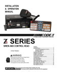
INSTALLATION
& OPERATION
MANUAL
3990 SERIES SIRENS
PATENT
PENDING
RLS
SERIES
SIRENS AND CONTROLS
Contents:
Introduction .....................................................................2
Standard Features ........................................................2
Unpacking & Pre-Installation......................................4
Installation & Mounting ................................................4
Set-Up and Adjustment ...............................................8
Operation ...................................................................... 1 0
M a i n t e n a n c e ................................................................ 1 5
Troubleshooting .......................................................... 1 6
Wiring Diagram ........................................................... 1 8
Diagnostic Function ................................................... 1 9
O p t i o n s .......................................................................... 1 9
Specifications .............................................................. 1 9
Parts List ....................................................................... 2 1
Warranty ........................................................................ 2 8
I M P O R TA N T:
Read all instructions and warnings before installing and using.
INSTALLER
This manual must be delivered to the end user
of this equipment.
Introduction
The 3990 series siren is a new series of remote control electronic sirens that has been designed to meet the
needs of all emergency vehicles. This series of sirens incorporates the popular features of the existing
Mastercom siren with microprocessor based circuitry and MOSFET technology. All of the original
features are available along with many new added features that are not available on any other Code 3 siren
such as; Park Kill, Instant "ON", Adj. Backlighting, " Scroll " Mode and more.
Sirens are an integral part of an effective audio/visual emergency warning system.
However, sirens are only short range secondary warning devices. The use of a siren
does not insure that all drivers can or will observe or react to an emergency warning
signal, particularly at long distances or when either vehicle is traveling at a high rate
of speed. Sirens should only be used in a combination with effective warning lights
and never relied upon as a sole warning signal. Never take the right of way for
granted. It is your responsibility to be sure you can proceed safely before entering an
intersection, driving against traffic, or responding at a high rate of speed.
The effectiveness of this warning device is highly dependent upon correct mounting
and wiring. Read and follow the manufacturer’s instructions before installing or using
device. The vehicle operator should check the equipment daily to insure that all
WARNING! this
features of the device operate correctly.
SIREN PRODUCTS:
To be effective, sirens must produce high sound levels that potentially can inflict
hearing damage. Installers should be warned to wear hearing protection, clear bystanders from the area and not to operate the siren indoors during testing. Vehicle
operators and occupants should assess their exposure to siren noise and determine
what steps, such as consultation with professionals or use of hearing protection
should be implemented to protect their hearing.
This equipment is intended for use by authorized personnel only. It is the user’s
responsibility to understand and obey all laws regarding emergency warning devices.
The user should check all applicable city, state and federal laws and regulations.
Code 3, Inc., assumes no liability for any loss resulting from the use of this warning
device.
Proper installation is vital to the performance of the siren and the safe operation of the
emergency vehicle. It is important to recognize that the operator of the emergency
vehicle is under psychological and physiological stress caused by the emergency
situation. The siren system should be installed in such a manner as to: A) Not reduce
the acoustical performance of the system, B) Limit as much as practical the noise
level in the passenger compartment of the vehicle, C) Place the controls within
convenient reach of the operator so that he can operate the system without losing eye
contact with the roadway.
Emergency warning devices often require high electrical voltages and/or currents.
Properly protect and use caution around live electrical connections. Grounding or
shorting of electrical connections can cause high current arcing, which can cause
personal injury and/or severe vehicle damage, including fire.
PROPER INSTALLATION COMBINED WITH OPERATOR TRAINING IN THE
PROPER USE OF EMERGENCY WARNING DEVICES IS ESSENTIAL TO INSURE
THE SAFETY OF EMERGENCY PERSONNEL AND THE PUBLIC.
!
Standard Features
The 3990 series sirens consist of remotely mounted siren amplifier with integral lighting control which is
operated by a compact control panel designed to be conveniently mounted near the operator. The models are
as follows:
3997/3997R
- Primary Tones: Wail, Yelp, Hi-Lo, Air Horn
- Secondary Tones: HyperYelp, HyperLo
- 6 auxiliary lighting controls
- Integral Arrow Stik Control
3998/3998R
- Primary Tones: Wail, Yelp, Hi-Lo, Air Horn
- Secondary Tones: HyperYelp, HyperLo
- 6 auxiliary lighting controls
2
2
3999/3999R
- Primary Tones: Wail, Yelp, Hi-Lo, Air Horn
- Secondary Tones: HyperYelp, HyperLo
- 6 auxiliary lighting controls
- Integral Arrow Stik Control
TM
- NIGHTPROBE Spotlight controller
optionally available
- 8 additional auxiliary relay outputs
optionally available
Switch A
Switch B
3-Level
Lighting
Switch
Switch
Switch
Switch
Switch
C
D
E
F
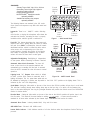
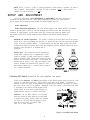
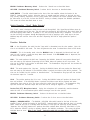
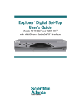
The following features are standard in the RLS series
sirens (tones and sequences may differ with model and
options):
Instant-On- There is no " ON/OFF " switch. Selecting
any
siren function, or keying the microphone will activate the
selected siren function, assuming the siren is properly
installed and the vehicle's ignition is switched on.
Park Kill- This feature deactivates the siren tones and
drops-out the Level 3 lighting when the vehicle is shifted
into park. Once PKILL is activated the siren will remain
deactivated until the vehicle is shifted into drive and an
action occurs such as depressing one of the siren
control switches, changing the position of the lighting
level switch or keying the microphone. Any of these
actions will cause the siren tones to start again.
Manual/Air
Horn
Pushbuttons
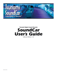
Figure 1 -
Special
Function
Switches
3999 Control Panel
3-Level
Lighting
Switch
Switch A
Switch B
Switch C
Switch D
Switch E
Switch F
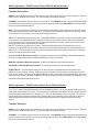
Adjustable Backlighting- Backlighting is independent
of siren power. Allows connecting to dimmer if desired.
Automatic Short Circuit Protection- The siren will
sense a short circuit on the speaker terminals and
automatically go to standby until the fault is removed.
Once the fault is removed the siren will return to normal
operation.
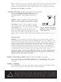
Manual
Air Horn
Switches
Special
Function
Switches
Lighting Level "3 " Dropout- When vehicle is shifted
Figure 1A - 3997R Control Panel
to PARK and the PKILL feature is connected, Level 3
lighting will dropout. This is a power down mode and can
be defeated by setting the 4 -position rear dip switch to the PKILL "OFF" position on the lighting board. This is
indicated by the "red" LED extinguishing.
Scroll Mode- Setting the slide switch on the rear of the siren to the SCROLL position will put siren in scroll mode.
This will allow "scrolling" through tones utilizing sharp taps on the horn ring, or a switch, via the Remote siren
input. In this mode holding the horn ring for prolonged durations will produce the Airhorn sound. See OPERATION
section for further details.
Hit-n-Go Mode - Setting the slide switch on the rear of the siren to the Hit-N-Go position will put the siren in the
Hit-n-Go mode. This mode will be most familiar to existing
users. A seven second override is
standard for all tones when activated by the Remote input. See OPERATION section for details.
Automatic Siren Tones - Industry standard Wail, Yelp, and Hi-Lo tones.
AIR HORN Tone - Electronic AIR HORN sound.
Instant Public Address - Public Address override of all siren functions when the microphone Push-to-Talk key is
pressed.
3
Status LED - An indicator LED, visible on the front of the remote siren amplifier indicates that the unit is on
when lighted.
Radio Rebroadcast - Broadcast Two-way radio reception over siren speakers.
coupled to prevent loading of the radio.
These inputs are transformer
Remote Siren Switching - The siren accepts either a positive or a ground (earth) signal, usually from the
vehicle's horn switch (or other user supplied switch), to remotely activate the MANUAL or AIR HORN functions.
(MANUAL or AIRHORN is selected via the slide switch located on the front panel of the siren amplifier. The
siren is factory set for a GND (Earth) signal and may be reconfigured to accept a positive signal. See
SETUP and Adjustments and Operation sections for details.
Noise Cancelling Microphone - Plug-in microphone that is easily unplugged for service or replacement.
Power Distribution Section - A three level progressive switch for primary warning light system control plus 6
push-on/push-off auxiliary switches.
Each auxiliary switch can be custom labeled with the supplied label kit. Each switch is backlighted when
activated to alert the operator. Each position of the progressive switch has its own indicator LED.
Horn Ring Transfer - Built in horn transfer relay that is automatically activated at Levels 2 and 3 of the
progressive warning light switch.
Unpacking & Preinstallation
After unpacking your RLS series
siren, carefully inspect the unit and
associated parts for any damage that
may have been caused in transit.
Report any damage to the carrier
immediately.
Installation &
Mounting
The RLS series siren control may be
mounted above the dash, below the
dash, on a tunnel or in a rack with
the mounting hardware supplied (see
Fig. 2). Ease of operation and
!
WARNING!
Figure 2
All devices should be mounted in accordance with the manufacturer’s instructions and securely
fastened to vehicle elements of sufficient strength to withstand the forces applied to the device. Ease
of operation and convenience to the operator should be the prime consideration when mounting the
siren and controls. Adjust the mounting angle to allow maximum operator visibility. Do not mount the
Control Head Module in a location that will obstruct the drivers view. Mount the microphone clip in a
convenient location to allow the operator easy access. Devices should be mounted only in locations
that conform to their SAE identification code as described in SAE Standard J1849. For example,
electronics designed for interior mounting should not be placed underhood, etc. Controls should be
placed within convenient reach* of the driver or if intended for two person operation the driver and/or
passenger. In some vehicles, multiple control switches and/or using methods such as “horn ring
transfer” which utilizes the vehicle horn switch to toggle between siren tones may be necessary for
convenient operation from two positions.
4
convenience to the operator should be the prime consideration when mounting the siren and controls
NOTE: Setups and adjustments will be made in subsequent steps, depending upon the model and options
purchased, that may require access to the rear area of the unit. Plan the installation and wiring accordingly.
Amplifier
Connections
Siren Amplifier Connector - As a standard feature, the Siren and Auxiliary sections of your unit
come equipped with a combination plug-in terminal block/connector. To terminate the wires, strip
approximately 1/4" of insulation from the end of each wire and insert it in the appropriate hole in the
terminal block. Tighten the setscrew and proceed to the next connection.
Should you ever have to remove the unit, pull the terminal block straight out. It will unplug from the
unit, leaving the wiring in place.
Terminal
Block
Connections
Light Control Terminal Plug- (see wiring diagram page 15)
COM - Connect to the wire from one 100 W ( 11 ohm ) speaker terminal 1.
SPKR - Speaker - Connect to the wire from 100 W ( 11 ohm ) speaker terminal 2.
NOTE: For all RLS sirens manufactured after April 2004, two 100W speakers may be connected in
parallel for 200 W operation. Correct phasing is important and can be accomplished by connecting
both speaker terminals marked " 1 " to the COM terminal and both speaker terminals marked " 2" to
the SPKR terminal. For sirens manufactured prior to April 2004, 200W operation was an optional
feature. Refer to the siren's wiring label to determine the power rating on these units.
REMOTE - Remote switch (Horn ring or foot switch). Circuit can be configured for both ground (earth)
or positive signals. A horn ring transfer circuit is standard in all 3990 series. Connect to the
"REMOTE" terminal on the Lighting Control Section terminal block. Unit is configured for a ground (
earth ) at the factory. See page 8 for details on configuring for a +12V input.
!
WARNING!
Larger wires and tight connections will provide longer service life for components. For high c u r r e n t
wires it is highly recommended that terminal blocks or soldered connections be used with shrink tubing to
protect the connections. Do not use insulation displacement connectors(e.g. 3M ® ) Scotchlock type
connectors). Route wiring using grommets and sealant when passing through compartment walls.
Minimize the number of splices to reduce voltage drop. High ambient temperatures (e.g. underhood) will
significantly reduce the current carrying capacity of wires, fuses, and circuit breakers. Use "SXL" type
wire in engine compartment. All wiring should conform to the minimum wire size and other
ecommendations of the manufacturer and be protected from moving parts and hot surfaces.
Looms, grommets, cable ties, and similar installation hardware should be used to anchor and protect all
wiring.
Fuses or circuit breakers should be located as close to the power takeoff points as possible and
properly sized to protect the wiring and devices. Particular attention should be paid to the location and
method of making electrical connections and splices to protect these points from corrosion and loss
of conductivity. Ground (Earth) terminations should
only be made to substantial chassis
components, preferably directly to the vehicle battery.
The user should install a circuit breaker sized to approximately 125% of the maximum Amp
capacity in the supply line to protect against short circuits. For example, a 30 Amp circuit breaker
should carry a maximum of 24 Amps.
DO NOT USE 1/4" DIAMETER GLASS FUSES AS THEY
ARE NOT SUITABLE FOR
CONTINUOUS DUTY IN SIZES ABOVE 15 AMPS. Circuit breakers are very sensitive to high
temperatures and will "false trip" when mounted in hot environments or operated close to their
capacity.
5
!
WARNING!
CONNECTION OF A 58 WATT SPEAKER TO THE SPKR TERMINAL WILL CAUSE THE
SPEAKER TO BURN OUT, AND WILL VOID THE SPEAKER WARRANTY!
The sound projecting opening should be pointed forward, parallel to the ground, and not
obstructed or muffled by structural components of the vehicle. Concealed or underhood
mountings in some cases will result in a dramatic reduction in performance. To minimize this
reduction, mount the speaker so the sound emitted is projected directly forward and obstruction by
vehicle components such as hoses, brackets, grille, etc. is minimized.
Electromechanical sirens and electronic siren speakers should be mounted as far from the
occupants as possible using acoustically insulated compartments and isolation mountings to
minimize the transmission of sound into the vehicle. It may be helpful to mount the device
on the front bumper, engine cowl or fender; heavily insulate the passenger compartment;
and operate the siren only with the windows closed.
Each of these approaches may cause significant operational problems, including loss of
siren performance from road slush, increased likelihood of damage to the siren in minor
collisions, and the inability to hear the sirens on other emergency vehicles.
APPROPRIATE TRAINING OF VEHICLE OPERATORS IS RECOMMENDED TO ALERT
THEM TO THESE PROBLEMS AND MINIMIZE THE EFFECT OF THESE PROBLEMS
DURING OPERATIONS.
LTG- Provides +12V to siren backlighting. Connect to a vehicle circuit that is powered when the
ignition switch is " on ". If backlighting dimming is desired, connect to the dash lights' circuit.
Caution- If connected to the battery the backlighting will be active at all times.
PKILL- This feature automatically deactivates siren tones when the vehicle is shifted into PARK.
When the 3-Level switch is set to Level-3, Level-3 will " dropout " when the vehicle is shifted to PARK
if this feature is enabled via the rear panel dip switch. Siren tones will be disabled until the vehicle is
shifted out of PARK and the front panel selector switched is either returned to standby ( or another
function is selected ) or the lighting level control is returned to level 1. This circuit is activated by a
negative signal. Connect this input to a circuit that is GROUNDED (Earth) when the vehicle is shifted
into PARK. It is the installer's responsibility to determine an appropriate location in the vehicle
circuitry to connect this wire.
RRB - Connect to one side of the two-way radio speaker.
RRB
- Connect to the second side of the two-way radio speaker.
InterClear® - Connect to the device or circuit that is to be activated by the InterClear feature. The
InterClear circuit is internally current limited at 1 Amp. Should your application require higher
currents, use the InterClear Power Booster Kit (# INTBS), available from your Code 3 supplier.
1/4" Male Quick-Connect Printed Circuit Board Terminals
+12V - Connect to a positive +12 volt DC source. It is recommended that the user protect this wire
with a 20 Amp fuse or circuit breaker located at the source. Use #14 gauge wire terminated with 1/4"
female, fully insulated quick-connect terminals only.
NEG - Connect to the negative terminal of the battery. This supplies ground (earth) to the siren. Use
#14 gauge wire terminated with 1/4" female, fully insulated quick-connect terminals only.
Power
Distribution
Connections
A #8 stud is provided on the rear of the unit and is intended for use ONLY as a convenient ground
(earth) " tie-point " for the light bar wiring. It is not an adequate ground (earth) for the siren or the
light bar. It is recommended all ground (earth) wires attached here be terminated with a crimpon ring terminal.
6
Terminal Plugs - Rear Panel- (See Wiring Diagram page 16)
IMPORTANT!
Remember auxiliary outputs A,B,D,E,F can supply a maximum of 20 Amps each for a
combined total of 30 Amps. Install appropriate fuses in each output wire as close to the siren
as possible.
SW A - Connect to the load to be controlled by Auxiliary Switch "A".
SW B -
Connect to the load to be controlled by Auxiliary Switch "B".
SW C NO - Connect to the load to be controlled by the normally-open contact on Auxiliary Switch "C".
SW C NC - Connect to the load to be controlled by the normally-closed contact on Auxiliary Switch
"C".
SW C COM - Common or power feed for Auxiliary Switch "C". Terminals are a SPDT circuit that
may be connected as latching (Push-On/Push-Off) or timed momentary circuit. This terminal may
also be connected to the vehicle's ignition circuit for added security when used with electric gun
locks. A switch accessible through the back of the siren control head allows the 10 second timed
output feature to be disabled thus making this switch operate as a Push-On/Push-Off function.
This circuit will handle up to 10 Amps, and should be protected with a fuse at the supply source.
SW D - Connect to the load to be controlled by Auxiliary Switch "D"
.
SW E - Connect to the load to be controlled by Auxiliary Switch "E".
SW F - Connect to the load to be controlled by Auxiliary Switch "F".
HORN RING - Connect to the wire coming from the vehicle horn switch at the steering wheel.
HORN - Connect to the vehicle horn or vehicle horn ring relay.
REMTE - Connect to the Remote terminal on the Siren Amplifier Connector.
#8 GAUGE RED WIRE PIGTAIL - provides power to the 3-Level, progressive lighting outputs only.
The wire can be ordered with an optional connector to allow for convenient removal. The
connector should be soldered to each wire, NOT crimped. This connection is designed to provide
50 amp service and therefore nothing smaller than #8 gauge wire should be connected to it. The
circuit breaker used should be sized for the actual load of the lighting used and located as close to
the battery positive as possible.
4 POSITION SCREW-TYPE TERMINAL BLOCK CONNECTOR
+12VAUX - Connect to the positive terminal of the battery with 30 Amp circuit protection. Locate the
fuse or circuit breaker at the battery and use #10 gauge wire minimum. This terminal provides output
power for switches A,B,D,E & F and must be connected whether these auxiliary outputs are used
or not.
IMPORTANT!
The Level 1-3 outputs can supply a maximum of 30 Amps each for a combined total of 50
Amps. Install appropriate fuses in each output wire as close to the siren as possible.
LEVEL 1 - Connect to the first level of warning lights (Green LED) position "1" on level switch.
LEVEL 2 - Connect to the second level of warning lights (Yellow LED) position "2" on level switch.
LEVEL 3 - Connect to the third level of warning lights (Red LED) position "3" on level switch.
7
NOTE: LEVEL 1, LEVEL 2, LEVEL 3, switch progressively. Switch position 1 provides +12 volts at
Level 1 terminal. Switch position 2 provides +12 volts at terminals 1 and 2. Switch position 3
provides +12 volts at terminals 1, 2, and 3.
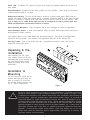
SETUP AND ADJUSTMENT
All of the adjustments, except MAXIMUM P.A. ADJUSTMENT, and setup switches are
accessible from the rear of the unit. Make these adjustments and position the setup switches
prior to placing the unit inside their bail bracket (see wiring diagram, page 15).
Audio Adjustments
Radio Rebroadcast Adjustment - Place the selector switch in the RADIO position. The trimmer
located on the rear panel of the siren sets the maximum level RRB will reach with the knob fully
clockwise. To adjust properly, set the volume knob fully clockwise and adjust the trimmer such
that normal two-way radio volume inside the vehicle produces the desired volume outside the
vehicle.
Maximum P.A. Volume Adjustment - This trimmer ( located on the front panel next to the volume
control knob ) sets the maximum level that the P.A. volume will reach with the front panel VOLUME
control in the fully clockwise position. To adjust properly, set the front panel volume control fully
clockwise and adjust the trimmer while keying the microphone until the maximum volume out of the
speaker is such that there is no feedback and is
intelligible.
Remote Input - The remote input can be configured to
accept either a positive +12V or negative GND ( Earth )
signal for actuation. All 3990 series sirens are shipped
setup to accept the GND (Earth) signal present on most
vehicles from the vehicle horn switch. To reconfigure the
Remote Input to accept a +12V signal the amplifier cover
must be removed (see exploded view, page 20). Move
both jumpers towards the "+ " position. Refer to detail "A"
for a complete illustration.
Factory Setting
4-Position DIP Switch (located on the siren amplifier, rear panel)
Gently set the SirenLock, and PKILL setup switches to the desired position using the point of a ball
point pin or some other similar tool. These switches are present on all models. If SirenLock is
switched on, all of the tones except AIRHORN, are muted until the Warning Light Switch is in either
the Level 3 or the Level 2 or 3 positions. Additionally, if the PKILL switch is on and the PKILL input
is connected to the vehicle's NSSW (Neutral Safety
Switch) circuit, all siren tones except AIRHORN are
muted while the vehicle is in PARK or NEUTRAL.
SirenLock - (sw 2-3) When switch 3 is on the siren
tones are allowed to sound when the 3-Level switch
is placed in the Level-3 position. When both switches
2 & 3 are on the siren tones are allowed to sound
when the 3-Level switch is placed in either
Level 2 or in Level 3 position.
Figure 3, 4-Position DIP Switch
8
PKILL- If this switch (sw 4) is in the on postition, lighting level-3 will "drop-out" when vehicle is shifted
to PARK. This is intended to reduce power consumption while vehicle is not moving. If it is not
desired to have level 3 "drop-out" this switch should be set to the " OFF " position on the dip switch.
Please note that DIP switch 1 is not used.
2-Position DIP Switch (located on the control head, rear panel)
Gently set the LightAlert, and Timed Output setup switches
to the desired position using the point of a ball point pin or
some other similar tool. These switches are present on all
models.
LightAlert - LightAlert is intended to alert the operator with an
audibe tone, when any lighting switch is activated. When this
switch is in the OFF position, the LightAlert tone is disabled.
Timed Output - Output "C" may be configured as a timed
output, providing a ten second, timed output for applications
such as electric gunlock. The SPDT relay allows an additional
Figure 4, 2-Position DIP Switch &
level of security to
WAIL/YELP Jumper (Push-Button
be added by connecting this output through the vehicle's
Control Heads only).
ignition circuit thereby requiring that the ignition be on in order
for the output to be activated. When this switch is in the OFF
position, output "C" becomes a latched output and may be toggled ON/OFF like switches A, B, D, E
& F.
Initial Siren Mode
WAIL/YELP - A three pin jumper located on the rear panel of the Push-Button version of the RLS
Control Head allows the siren may be configured to automatically start the siren in either WAIL or YELP
mode when the 3-level lighting switch is moved to a position higher than the selected SirenLock level.
Inserting the jumper across the left two pins will cause the Initial Siren Mode (ISM) to be WAIL.
Similarly, moving the jumper to the right two pins will select YELP mode. If no siren tone is desired
the jumper should be moved to a position which only covers one of the pins. In this position, the
siren tones may still be activated by the front panel switches or the vehicle's horn switch but will not
be automatically started when the position of the 3-level lighting control switch is changed.
Note that this jumper is not used on the 399xR control heads. For systems equipped with the
399xR Rotary Switch version of the RLS Control Head, the initial siren tone is selected by the
position of the front panel rotary control switch.
Hit-N-Go / Scroll Selector Switch (located on the siren amplifier, rear panel)
The siren has two distinct modes, Hit-N-Go and Scroll. Set rear panel slide switch, Figure 3, to the
desired mode by sliding left or right. See operation section for a detailed description of operation in
each mode.
Custom
Labeling
Labels supplied with the RLS series siren should be selected and placed in the appropriate windows.
Refer to Figure 1for the RLS Control Head switch A-F window designations.
!
WARNING!
"Wail" and "Yelp" tones are in some cases
siren tones for calling for the right of way.
and "Hyperlo" in some cases do not provide
these tones beused in a secondary mode to
9
(such as in the state of California) the only recognized
Ancillary tones such as "Air Horn", "Hi-Lo", "Hyperyelp",
as high a sound pressure level. It is recommended that
alert motorists to the presence of an emergency vehicle.
P.A. Volume Knob
This control adjusts the level of the P.A. audio produced when keying the microphone and speaking
into it. This control also controls the Radio Re-broadcast level when in the " RRB " switch is on. (see
SETUP, Radio Rebroadcast Adjustment).
Operation
IMPORTANT !
The RLS Series Siren has two distinct modes of operation. These are Hit-N-Go mode and SCROLL
mode. The desired mode of operation can be selected via the amplifier rear panel slide switch. Each
mode will affect the siren operation as described below. The Hit-N-Go mode should be most familiar to
existing
users.
The configuration of the SirenLock and Park Kill features
will, in some cases, prevent the siren from producing
siren tones. The siren will not produce tones when the
vehicle is in "PARK" if the PKILL feature has been
connected and the PKILL enable switch is ON. If the
Siren Lock feature is enabled (lighting Level-2 or 3), the
siren will not produce tones until the appropriate lighting
level is selected by the progressive warning light switch.
To test the siren tones the vehicle must not be in "PARK".
The following assumes that PKILL has not been activated
and that the progressive warning light switch is set to the
appropriate position.
Figure 5, Siren Amplifier, Front Panel
Switch Operation - Hit-N-Go Mode Selected
Function
Description
RRB - In the ON position, the audio from the 2-way radio is rebroadcast over the siren speaker. Note, the siren
is not disabled in this mode. The siren will generate siren tones if selected then revert to RRB mode.
STANDBY - This is the standby mode. If the MANUAL button is depressed the Manual wail tone will ramp up
until it reaches a peak then ramp down when released. If the AIR HORN button is depressed, the Air Horn
sound will be produced.
WAIL - This mode produces the Wail tone. Depressing the AIR HORN button will produce the Air Horn sound
and when released will return siren to Wail tone. The Remote/Horn Ring input will activate the Interclear output
and cause the tone to change to Yelp for 7 seconds.
YELP - This position produces the Yelp tone. Pushing the MANUAL button will produce the Manual Wail tone
until released. If the AIRHORN button is pushed, the Airhorn sound will be produced and when released will
return the siren to Yelp. The Remote/Horn Ring input will activate the Interclear output and cause the tone to
change to HyperYelp for 7 seconds.
HI-LO - This position produces the Hi-Lo tone. Pushing the MANUAL button will Manual Wail tone until
released. If the AIRHORN button is pushed, the Airhorn sound will be produced and when released will return
siren to Hi-Lo. The Remote/Horn Ring input will activate the Interclear output and cause the tone to change to
HyperLo for 7 seconds.
Push-to-Talk (PTT) Microphone Switch - Keying the microphone will automatically override whatever mode
the siren is in and broadcast public address messages over the siren speaker.
10
MANUAL Pushbutton Momentary Switch - Produces the
AIR HORN
Pushbutton Momentary Switch-
Manual tone as described above.
Produces the Air Horn tone as described above.
SLIDE SWITCH - The slide switch located on the front of the siren amplifier selects the function for the
REMOTE (external switch) circuitry. When the siren is in standby mode and switch is to the right, the Horn
Ring circuitry remotely "depresses" the AIR HORN button and it produces the effects outlined above. When
the slide switch is to the left, it allows the REMOTE circuitry to remotely "depress" the MANUAL pushbutton.
This causes the effects described above to occur.
Switch Operation - Scroll
Mode Selected
The " Scroll " mode is designed to allow the user to scroll through Wail, Yelp, HyperYelp and Airhorn tones by
utilizing the Remote input on the siren. This will usually be connected to the vehicle Horn Ring circuit. When the
three level lighting control switch is in postition 2 or 3, the Horn Ring transfer relay is energized. The user can
use the Horn Ring to sequence through Wail,Hyperyelp and Yelp by applying a quick, sharp tap on the horn.
Additional taps will scroll the siren to the next tone. Depressing the horn for longer periods will produce "
Airhorn".
Function Selection
RRB - In the ON position, the audio from the 2-way radio is rebroadcast over the siren speaker. Note, the
siren is not disabled in this mode. The siren will generate siren tones if selected then revert to RRB mode.
STANDBY - This is the standby mode, when the MANUAL button is depressed the Manual wail tone will
ramp up until it reaches a peak then ramp down when released. If the AIR HORN button is depressed, the
Air Horn sound will be produced.
WAIL - This mode produces the Wail tone. Depressing the MANUAL button will now produce Manual wail
tone and ramp up until released. Depressing the AIR HORN button will produce the Air Horn sound. The
siren can be scrolled in this position as described above. The Remote/Horn Ring input will also activate the
Interclear output for 7 seconds.
YELP - This mode produces the Yelp tone. Pushing the MANUAL button will now produce the Manual wail
tone and ramp up until released. If the AIRHORN button is pushed, the Airhorn sound will be produced. The
siren can be scrolled from this position as described above. The Remote/Horn Ring input will also activate
the Interclear output for 7 seconds.
HI-LO - This position produces the Hi-Lo tone. Pushing the MANUAL button will produce the Manual Wail
tone until released. If the AIRHORN button is pushed, the Airhorn sound will be produced and when
released the siren return to Hi-Lo.The siren cannot be scrolled from this position. The Remote/Horn Ring
input will activate the Interclear output and cause the tone to change to HyperLo for 7 seconds.
Push-to-Talk (PTT) Microphone Switch - Keying the microphone will automatically override whatever
mode the siren is in and broadcast public address messages over the siren speaker.
MANUAL Pushbutton Momentary Switch - Produces the Manual tone as described above.
AIR HORN
Pushbutton Momentary Switch - Produces the Air Horn tone as described above.
MANUAL / AIRHORN SWITCH - The MANUAL / AIRHORN slide switch located on the front of the siren
amplifier, Figure 5, selects the function for the REMOTE (external switch) circuitry when the siren is in standby
mode. When the the siren is in standby mode and switch is to the right, the Horn Ring circuitry remotely
"depresses" the AIR HORN button and it produces the effects outlined above. When the slide switch is to the
left, it allows the REMOTE circuitry to remotely "depress" the MANUAL pushbutton. This causes the effects
described above to occur. When in the "Scroll " mode this switch has no effect unless in STANDBY
position.
11
Switch Operation - 399xR Control Head, Hit-N-Go Mode Selected
Function Description
RADIO - In the RADIO position, the audio from the 2-way radio is rebroadcast over the siren speaker. Note: the
siren tones are disabled in this mode. The Air Horn switch will operate normally.
STANDBY - In STANDBY mode no siren tone is produced. If the MANUAL button is depressed the Manual wail
tone will ramp up until it reaches a peak then ramp down when released. If the AIR HORN button is depressed,
the Air Horn sound will be produced.
WAIL - This mode produces the Wail tone. Depressing the AIR HORN button will produce the Air Horn sound
and when released will return siren to Wail tone. The Remote/Horn Ring input will activate the Interclear output
and cause the tone to change to Yelp for approximately 60 seconds.
YELP - This position produces the Yelp tone. Pushing the MANUAL button will produce the Manual Wail tone
until released. If the AIRHORN button is pushed, the Airhorn sound will be produced and when released will
return the siren to Yelp. The Remote/Horn Ring input will activate the Interclear output and cause the tone to
change to HyperYelp for approximately 60 seconds.
HI-LO - This position produces the Hi-Lo tone. Pushing the MANUAL button will Manual Wail tone until
released. If the AIRHORN button is pushed, the Airhorn sound will be produced and when released will return
siren to Hi-Lo. The Remote/Horn Ring input will activate the Interclear output and cause the tone to change to
HyperLo for approximately 60 seconds.
Push-to-Talk (PTT) Microphone Switch - Keying the microphone will automatically override whatever mode
the siren is in and broadcast public address messages over the siren speaker.
MANUAL Pushbutton Momentary Switch - Produces the Manual tone as described above.
AIR HORN Pushbutton Momentary Switch- Produces the Air Horn tone as described above.
SLIDE SWITCH - The slide switch located on the front of the siren amplifier selects the function for the
REMOTE (external switch) circuitry. When the siren is in standby mode and switch is to the right, the Horn
Ring circuitry remotely "depresses" the AIR HORN button and it produces the effects outlined above. When the
slide switch is to the left, it allows the REMOTE circuitry to remotely "depress" the MANUAL pushbutton. This
causes the effects described above to occur.
Switch Operation - 399xR Control Head, Scroll Mode Selected
The " Scroll " mode is designed to allow the user to scroll through Wail, Yelp, HyperYelp and Airhorn tones by
utilizing the Remote input on the siren. This will usually be connected to the vehicle Horn Ring circuit. When the
three level lighting control switch is in postition 2 or 3, the Horn Ring transfer relay is energized. The user can
use the Horn Ring to sequence through Wail,Hyperyelp and Yelp by applying a quick, sharp tap on the horn.
Additional taps will scroll the siren to the next tone. Depressing the horn for longer periods will produce "
Airhorn".
Function Selection
RADIO - In the RADIO position, the audio from the 2-way radio is rebroadcast over the siren speaker. Note: the
siren tones are disabled in this mode. The Air Horn switch will operate normally.
STANDBY - In STANDBY mode no siren tone is produced. If the MANUAL button is depressed the Manual wail
tone will ramp up until it reaches a peak then ramp down when released. If the AIR HORN button is depressed,
the Air Horn sound will be produced.
12
WAIL - This mode produces the Wail tone. Depressing the MANUAL button will now produce Manual wail tone
and ramp up until released. Depressing the AIR HORN button will produce the Air Horn sound. The siren can be
scrolled in this position as described above. The Remote/Horn Ring input will also activate the Interclear output
for approximately 60 seconds.
YELP - This mode produces the Yelp tone. Pushing the MANUAL button will now produce the Manual wail tone
and ramp up until released. If the AIRHORN button is pushed, the Airhorn sound will be produced. The siren can
be scrolled from this position as described above. The Remote/Horn Ring input will also activate the Interclear
output for approximately 60 seconds.
HI-LO - This position produces the Hi-Lo tone. Pushing the MANUAL button will produce the Manual Wail tone
until released. If the AIRHORN button is pushed, the Airhorn sound will be produced and when released the
siren return to Hi-Lo.The siren cannot be scrolled from this position. The Remote/Horn Ring input will activate
the Interclear output and cause the tone to change to HyperLo for approximately 60 seconds.
Push-to-Talk (PTT) Microphone Switch - Keying the microphone will automatically override whatever mode the
siren is in and broadcast public address messages over the siren speaker.
MANUAL Pushbutton Momentary Switch - Produces the Manual tone as described above.
AIR HORN Pushbutton Momentary Switch - Produces the Air Horn tone as described above.
MANUAL / AIRHORN SWITCH - The MANUAL / AIRHORN slide switch located on the front of the siren
amplifier, Figure 5, selects the function for the REMOTE (external switch) circuitry when the siren is in standby
mode. When the the siren is in standby mode and switch is to the right, the Horn Ring circuitry remotely
"depresses" the AIR HORN button and it produces the effects outlined above. When the slide switch is to the
left, it allows the REMOTE circuitry to remotely "depress" the MANUAL pushbutton. When in the "Scroll "
mode this switch has no effect unless in STANDBY position.
LED STATUS INDICATOR - The green
off or standby mode when unlighted.
-Lighting
LED status indicator indicates the the siren amplifier is on when lighted;
Controls-
WARNING LIGHTS 3 LEVEL PROGRESSIVE SLIDE SWITCH:
POSITION 1 - Supplies power to Lighting Level 1.
Illuminates Green LED.
Activates LightAlert if supplied
POSITON 2 - Supplies power to Lighting Levels 1 & 2. Illuminates Green and Yellow LED's.
LightAlert and SirenLock options if supplied.
Position 3- Supplies power to Lighting Levels 1,2, & 3.
LightAlert and SirenLock if supplied.
Activates
Illuminates Green, Yellow, AND Red LED's.
Activates
Auxiliary Switches:
AUXILIARY SWITCH "A" - Supplies power to the load connected to terminal SW A.
AUXILIARY SWITCH "B" - Supplies power to the load connected to terminal SW B.
AUXILIARY SWITCH "C" - Operates circuit connected to terminals SWC NO, SWC NC, SWC COM.
Functions as a momentary activation, 10 sec. timed switch or as a latching switch. The timed output function
may be enabled/disabled by the two position switch located on the rear of the siren control head.
AUXILIARY SWITCH "D" - Supplies power to the load connected to terminal SW D.
13
AUXILIARY SWITCH "E" - Supplies power to the load connected to terminal SW E.
AUXILIARY SWITCH "F" - Supplies power to the load connected to terminal SW F.
NOTE: The six auxiliary switches described above have their own individual LED which is dimly illuminated for
back lighting and bright to indicate that the circuit is On. These switches will also activate the LightAlert feature
if it is enabled.
LightAlert - The LightAlert option will produce an audible "beep" on a periodic basis if the Progressive Warning
Light Switch or any of the Auxiliary Switches are on. A switch accessible through the back of the siren control
head allows this feature to be disabled if desired.
SirenLock - The SirenLock option, when not defeated by means of the switches accessible on the rear panel of
the siren amplifier, allows siren tones to be produced only when the Warning Light Switch is in the Lighting
Level 2 (Green and Yellow LED's) or Lighting Level 3 (Green, Yellow, and Red LED's) position. Air Horn, Radio
Rebroadcast, and Public Address are unaffected by this option.
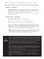
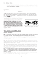
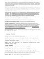
Special Function Switches (Models 3997, 3997R, 3999 & 3999R only)
RLS Siren Models 3997, 3997R, 3999 & 3999R have five (5) "Special
Function" switches which provide a means of control, on properly
equipped installations, for an ArrowStik for Models 3997 & 3997R and
TM
an ArrowStik, NIGHTPROBE spotlight, and the RLS Auxiliary Relay
Module for Models 3999 & 3999R. On Models 3997 and 3997R these
switches control the function of the ArrowStik. On Models 3999 and
3999R, the function of these five switches is determined by the Special
Function Select Button. Each time the Select switch is Depressed the
Special Function Mode will scroll to the next mode as indicated by the
illuminated legend of the Special Function Indicator (see Figure 6). The
function of the switches in each mode is described below.
Figure 6,
Special Function Switches
ArrowStik - Using the control unit's SELECT switch, select the
ArrowStik mode. When in ArrowStik mode the five "Special Function" switches provide push-on / push-off
control of an ArrowStik. These switches operate intuitively for the Left, Right, Center-Out and Rear Flash
ArrowStik functions. Depressing the Up Arrow will cause the ArrowStik to toggle between Bright and Dim mode.
Please note that when the ArrowStik is in Dim mode, depressing the active function switch again will toggle the
ArrowStik back to Bright mode. Depressing the active function switch a second time will toggle the ArrowStik
function OFF.
TM
NIGHTPROBE - The RLS Spotlight Control Module (option B394) is required to operate this function. Using
the control unit’s SELECT switch, select the SPOT mode. In this mode, depressing and holding the LEFT,
RIGHT, UP or DOWN keys will cause the NIGHTPROBE TM to rotate in the appropriate direction. The spotlight
will accelerate from it’s slowest speed to full speed over a two second period and stop instantly when the switch
is released. This allows for very precise positioning of the light. Depressing and releasing the center switch
while in the SPOT mode will cause the lamp to toggle ON and OFF. Please refer to the RLS NIGHTPROBE TM
Control Module, User Manual (p/n 10938) for detailed instructions and further cautionary information on
the installation and wiring of the RLS NIGHTPROBE TM Control and NIGHTPROBE TM Spotlight systems.
AUX1 / AUX2 - The RLS Auxiliary Relay Module is (option B396) is required to operate this function. Using the
control unit’s SELECT switch, select the AUX1 mode. In this mode, depressing the LEFT, UP, RIGHT or
DOWN keys will activate outputs 1,2,3 or 4 respectively. Similiarly, when AUX2 mode is selected, depressing
the LEFT, UP, RIGHT or DOWN keys will activate outputs 5,6,7 or 8 respectively. These are ON / OFF
latching functions. Each output will toggle ON when it’s switch is depressed the first time and OFF when it’s
14
depressed a second time. Depressing the center switch will set all four outputs of the selected mode to OFF.
Please refer to the RLS Auxiliary Relay Control Module, User Manual (p/n 10947) for detailed instructions
and further cautionary information on the installation and wiring of the RLS Auxiliary Relay Module.
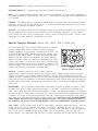
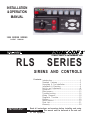
Contol Head Wiring
MAINTENANCE
Your Code 3 3990 series siren has been designed to provide trouble free service. In case of difficulty, see
Troubleshooting (page 16,17 ). Also check for shorted or open wires. The primary cause of short circuits has
been found to be wires passing through firewalls, roofs, etc. If further difficulty persists, contact the factory for
troubleshooting advice or return instructions. Public Safety Equipment, Inc. maintains a complete parts
inventory and service facility at the factory and will repair or replace (at the factory's option) any unit found to be
defective under normal use and in warranty. Any attempt to service a unit in warranty by anyone other than a
factory authorized technician without express written consent by the factory, will void the warranty. Units out of
warranty can be repaired at the factory for a nominal charge on either a flat rate or parts and labor basis.
Contact the factory for details and return instructions. Public Safety Equipment, Inc. is not liable for any
incidental charges related to the repair or replacement of a unit unless otherwise expressly agreed to in writing.
15
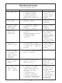
TROUBLESHOOTING
(Refer to wiring diagram page 15)
PROBLEM
PROBABLE
CAUSE
REMEDY
EXTERNAL 20A
FUSE BLOWS.
A. PARK KILL ACTIVATED
B. SIRENLOCK ENGAGED
C. SHORTED SPEAKER OR
SPEAKER WIRES. SIREN IN
OVER CURRENT PROTECTION
MODE.
A. AMPLIFIER POWER WIRES
REVERSED POLARITY
A. SHIFT VEHICLE OUT
OF PARK.
B. SELECT PROPER
SIRENLOCK LEVEL
C. CHECK
CONNECTIONS
A. CHECK POLARITY
B. REPLACE
SPEAKER(S)
NO OUTPUT FROM
SPEAKER, TONES
HEARD INSIDE
AMP. MODULE.
A. SPEAKER NOT CONNECTED/
OPEN CIRCUIT IN SPEAKER
WIRING
B. DEFECTIVE SPEAKERS
SIREN TONES
VOLUME TOO
LOW/GARBLED.
A. LOW VOLTAGE TO SIREN
AMPLIFIER
B. HIGH RESISTANCE IN WIRING/
DEFECTIVE SPEAKER
C. SPEAKERS PHASED
IMPROPERLY
A. CHECK SPEAKER
WIRING
B. REPLACE
SPEAKER(S)
A. CHECK WIRING FOR
BAD CONNECTIONS/
CHECK VEHICLE
CHARGING SYSTEM
B. CHECK SPEAKER(S)
WIRING/REPLACE
SPEAKER(S)
C. REFER TO PAGE 5
FOR PROPER PHASING
(200W OPTION)
HIGH RATE OF
SPEAKER FAILURE.
A. HIGH VOLTAGE TO SIREN
B. 58 WATT SPEAKER CONNECTED
TO 100 WATT TAP.
58 WATT NOT
ALLOWED.
A. CHECK VEHICLE
CHARGING SYSTEM
B. USE CORRECT
SPEAKER
SIREN CONTINUES
TO OPERATE FOR
7 SEC. AFTER
MANUAL BUTTON/
HORN RING IS
RELEASED.
A. "HIT-N-GO" FEATURE ENGAGED.
NORMAL OPERATION
INTERCLEAR WILL NOT
POWER AUXILIARY
DEVICES.
A. THERE IS A SHORT IN THE
WIRING, OR THE LOAD IS
GREATER THAN 1 A.
P.A. VOLUME LOW OR
NO P.A. AT ALL.
VOLUME CONTROL
FULLY CLOCKWISE.
A. DEFECTIVE MICROPHONE
B. MAXIMUM P.A. VOLUME
TRIMMER MISADJUSTED. SEE
SETUP AND ADJUSTMENT
SECTION.
C. MICROPHONE NOT
COMPLETELY PLUGGED IN.
D. COMMON MICROPHONE
CIRCUIT NOT PROPERLY WIRED.
E. INCORRECT MICROPHONE.
NO
SIREN OUTPUT.
16
A. CHECK FOR
SHORTS. INSTALL
INTERCLEAR
BOOSTER KIT (PART
#INTBS)
A. REPLACE
MICROPHONE
B. REFER TO SETUP
AND ADJUSTMENT
SECTION
C. PLUG MICROPHONE
IN SECURELY
D. CHECK WIRING
E. CALL PSE FOR LIST
OF ADAPTABLE
MICROPHONES
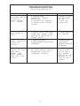
TROUBLESHOOTING
(Refer to wiring diagram page 15)
PROBLEM
PROBABLE
CAUSE
REMEDY
RRB VOLUME LOW, OR
NO RRB AT ALL.
VOLUME CONTROL
FULLY CLOCKWISE.
A. MAXIMUM RADIO
REBROADCAST
TRIMMER
MISADJUSTED
B. RRB WIRES NOT CONNECTED
TO TWO-WAY RADIO EXTERNAL
SPEAKER
A. REFER TO SETUP
AND ADJUSTMENT
SECTION
B. CHECK RRB
CONNECTIONS
SIREN SOUNDS BY
ITSELF
A. REMOTE SWITCH (HORN RING)
WIRING FROM TERMINAL REMOTE
SHORTING TO POSITIVE OR TO
GROUND (EARTH).
A. CHECK WIRING FOR
ANY SHORTING.
A. SUPPLY FUSE OPEN
B. SIREN TERMINAL NEGATIVE NOT
GROUNDED
A. REPLACE FUSE.
B. RECONNECT
TERMINAL NEGATIVE
TO GROUND.
A. VEHICLE CIRCUIT BREAKERS
NOT RATED PROPERLY, AND ARE
OVERHEATING, OR ARE NOT
FUNCTIONING
PROPERLY
A. REFER TO
SPECIFICATIONS
SECTION, PAGE 17.
USE A BREAKER
RATED AT 1.25x THE
AMPERAGE OF THE
EXPECTED LOAD
CURRENT.
POWER DISTRIBUTION
SECTION NOT
WORKING
SIREN RUNS
PROPERLY BUT SHUTS
DOWN WHILE
RUNNING, THEN
STARTS RUNNING
AGAIN AFTER A FEW
MINUTES
17
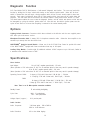
NEG
LVL 1
PARK SWITCH
}
BROWN
ORANGE
VIOLET
YELLOW
BLUE
+12V
30A MAX
+
}
TO LIGHTBAR
18
TO ARROW
STIK
#8 GA. WIRE,
50A BREAKER
TO BATTERY
+12VDC
-
TO IGNITION
CONTROLLED +12VDC
BAT T E RY
USE 1/4" FEMALE INSULATED
QUICK-CONNECTS
ONLY - #14 - 16 GA
#14 GA
20A MAX
DASH LIGHT SWITCH / IGNITION SWITCH
10 GA
ALL AUXILIARY +12V OUTPUTS
SHOULD BE FUSED WITH A
20 AMP MAX FUSE/BREAKER
UNLESS OTHERWISE SPECIFIED
LVL 2
NEG
TO TWO-WAY RADIO
SPEAKER
+12V
10AMP MAX
FUSE
LVL 3
}
+12V
POWERS AUXILIARY
SWITCHES A,B,D,E,F
30AMPS TOTAL
MAX. LOAD
+12V
AUX
{
1 AMP MAX
10 SEC. TIMED
OUTPUT
1
ARROW STIK
GROUND
18 GA
BREAK VEHICLE
CONNECTION
CONNECT TO UTILIZE INTERNAL
HORN RELAY OR CONNECT TO
EXTERNAL SWITCH
1
2
NO 58W SPEAKER CONNECTIONS
2
SW F
BK LTG
P KILL
RRB
RRB
INTERCLEAR
100W SPEAKER ONLY
ADDITIONAL 100W SPEAKER
IF OPTION IS SPECIFIED
SW A
SW B
SW C N.C.
SW C COM
SW C N.O.
SW D
SW E
16GAC O M
16GASPKR
HORN RING
HORN
REMOTE
Diagnostic
Function
RLS Siren Models 3997 & 3999 features a "walk-around" diagnostic test function. The user may invoke this
function by holding the "Air Horn" switch while turning on the vehicle's ignition switch. When the "Air Horn"
switch is released the siren will begin a timing sequence which will turn on each control output for about two
seconds. Each output, including the Arrow Stik (in Flash mode) and the siren tones will be cycled during this
sequence. The siren tones will not be heard if the Park-Kill feature is being used and the vehicle is in Park.
This timed feature enables the user to start the diagnostic function, exit the vehicle and observe a brief test can
be interrupted by cycling the vehicle's ignition switch off. After the test, the vehicle's ignition power must be
cycled off and back on to insure that everything is restored to the normal standby mode.
Options
Lighting Switch Connector- Connectors which when soldered to the #8 wire and the user supplied power
wire offers quick disconnect service.
Microphone Extension Cable- A twenty (20) ft. microphone extension cable.
mounted up to twenty feet from the driver's area.
Allows the siren amplifier to be
TM
NIGHTPROBE Spotlight Control Module - Allows use of the RLS 3999 Siren Control to provide full control
TM
of the NIGHTPROBE spotlight with linear acceleration from stop to full speed.
Auxiliary Relay Module - Provides eight (8) additional switched +12VDC outputs at up to 10A each, limited to
a maximum total combined current of 60A.
Specifications
Siren Section
Input Voltage 10 to 16 VDC, negative ground (earth) - 12V units
(Note: Operation of 12V units above 15 VDC for an extended period of time may result in speaker damage.)
20 to 30 VDC, negative ground (earth) - 24V units
(Note: Operation of 24V units above 30 VDC for an extended period of time may result in speaker damage.)
Operating Current 100W:
8 Amps @ 13.6V with 11-ohm load ( 100 W Spkr ) - 12Vunits
4. 5 Amps @ 27.6V with 11-ohm load ( 100 W Spkr ) - 24Vunits
200W:
14 Amps @ 13.6V with 5.5-ohm load ( 2- 100 W Spkr ) - 12V units
9 Amps @ 27.6V with 5.5-ohm load ( 2- 100 W Spkr ) - 24V units
Note: There is no 58 Watt speaker connection available.
Standby Current:
25 mA excluding backlighting
Cycle Rate:
WAIL - 11 cycles/minute.
YELP - 200 cycles/minute.
Voltage Output ( approx. )
64 V peak-to-peak
Audio Section
Audio Response:
3 dB down points - 500 to 3000 hz.
1000 hz. 0 dB Reference
Audio Distortion:
10% or less below clipping.
19
Lighting Section
Warning Light Control:Progressive switching, 3 levels
50 Amps. maximum combined total to #8 wire
Audible alarm (optional).
Level 1
30A maximum
Green LED Indication
Level 2
30A maximum
Yellow LED Indication
Level 3
30A maximum
Red LED indication.
Auxiliary Control - SPST ( Aux. Switches A, B, E, D, F )
Accessory Switch operation - Push-on/off operation.
Independent circuits - 5
30 Amps. maximum combined total
20 Amps. maximum load for any single output A,B,E,D or F
LED indication.
Audible alarm
Auxiliary Control - SPDT (Aux. Switch "C"):
Accessory Switch operation -Momentary (switch located on rear of siren control)
Independent circuits - 1
10 Amps. maximum connected load.
LED indication.
Audible alarm
Timed Output
Horn Transfer Relay - SPDT:
Activated in Level 2 and 3.
10 Amps. maximum connected load.
System - Weight:
Amplifier
4.25 lbs (1.9 Kg)
Control Unit
0.5 lbs (.226 Kg)
Microphone &
Hardware
2.0 lbs (.9 Kg)
Size: Amplifier -
7.5" L x 7.5" W x 3.25" H
Control Unit - 7" L x 3.5" H x 1.5" D
Temperature: -22°F - +149°F (-30°C - +65°C) SAE Equipment Type EVS1
20
21
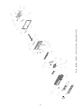
88
Push Button Switch Control Head, Exploded View
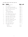
Push Button Switch Control Head, Parts List
Ref No.
Description
Part No.
Qty.
1
8 - 32 x 1/4" Machine Screw
T01385
2
2
Knob, Rectangular
T01917
1
3
4 - 40 x 3/8", Pan Hd Phil, Black Oxide
T06937
7
4
Switch Actuator Keypad, 1x6, Silicone Rubber
T10878
1
5
Enclosure, Control Head, RLS Siren
T10880
1
6
Standoff, 4 - 40 x .75"
T10890
2
7
Label, Faceplate, Model 3998
T10901
1
8
Label, Faceplate, Model 3999
T10902
1
9
Label, Configuration (Part of Wiring Label)
T10904
1
10
1/4 - 20 x .375", Hex Washer Hd, Zinc
T10912
2
11
Switch Actuator, Small Arc, RLS Sirens
T10913
2
12
Switch Actuator, Large Arc, RLS Sirens
T10914
2
13
Switch Actuator, Oval, RLS Sirens
T10915
3
14
Switch Actuator, Rectangular, RLS Sirens
T10916
2
15
Bracket, Control Head, RLS Sirens
S71528
2
16
Switch Assembly w/Harness
S55229
1
17
E-Tray, Control Head, RLS Sirens
S71531
1
18
PCB Assembly, Control Head,
1
Model 3998
S71552
Models 3997 & 3999
S71562
22
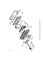
23
Rotary Switch Control Head, Exploded View
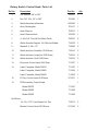
Rotary Switch Control Head, Parts List
Ref No.
Description
Part No.
Qty.
1
Flat Washer, 3/8" x .020"
T00667
1
2
Nut, 3/8" -32 x 1/2" x .090"
T01082
1
3
Switch Assembly w/Harness
S55229
1
4
Knob, Rectangular
T01917
1
5
Knob, Selector
T03537
1
6
Insert, Selector Knob
T03538
1
7
4 - 40 x 3/8", Pan Hd Phil, Black Oxide
T06937
8
8
Switch Actuator Keypad, 1x6, Silicone Rubber
T10878
1
9
Standoff, 4 - 40 x .75"
T10890
2
10
Switch Actuator, Small Arc, RLS Sirens
T10913
2
11
Switch Actuator, Large Arc, RLS Sirens
T10914
2
12
Switch Actuator, Oval, RLS Sirens
T10915
2
13
Enclosure, Control Head, RLS Siren
T11207
1
14
Label, Faceplate, Model 3997R
T11270
1
Label, Faceplate, Model 3998R
T11268
1
Label, Faceplate, Model 3999R
T11269
1
15
E-Tray, Control Head, RLS Sirens
S71531
1
16
PCB Assembly, Control Head,
1
Model 3997R
T11297
Model 3998R
T11298
Model 3999R
T11299
Not Shown:
1/4 - 20 x .375", Hex Washer Hd, Zinc
T10912
2
Bracket, Control Head, RLS Sirens
S71528
2
24
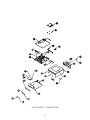
Siren Amplifier, Exploded View
25
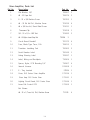
Siren Amplifier, Parts List
Ref No.
Description
Part No.
Qty.
1
Flat Washer, 3/8"
T00667
2
2
#8 - 32 Keps Nut
T00674
2
3
8 - 32 x 5/8 Machine Screw
T00763
1
4
#6 - 32 Rd Hd Phil., Machine Screw
T01030
6
5
#6 x 3/8 Hex Hd, Sheet Metal Screw
T01031
1
T01058
1
T01082
2
6
Tinnerman Clip
7
3/8 - 32 x 1/2 x .090" Nut
8
#4 - 40 Nylon Insert Stop Nut
9
Circuit Board Standoff
T05172
4
10
Fuse, Blade Type Term., 10A
T06013
1
11
Transistor Insulating Pad
T06363
2
12
Serial Number Label
T06140
1
13
Airbag Warning Label
T09937
1
14
Label, Wiring and Backplate
T10904
1
15
Spacer, Nylon, PCB Mounting 1/4"
T10907
4
16
Internal Harness
S55068
1
17
E - Tray, Inserted
S71534
1
18
Cover, RLS Series Siren Amplifier
S71536
1
S71541
1
19
T03594
Siren Amp. RLS Series Siren
2
20
Lighting Circuit Board, RLS Series Siren
S71546
1
21
Arrow Stik Control PCB
S71560
1
T11135
4
Not Shown:
#6 - 32 x 2, Truss Hd., Phil., Machine Screw
26
NOTES
27
WA R R A N T Y
Code 3, Inc.'s emergency devices are tested and found to be operational at the time of
manufacture. Provided they are installed and operated in accordance with manufacturer's
recommendations, Code 3, Inc. guarantees all parts and components except the lamps to a period
of 1 year (unless otherwise expressed) from the date of purchase or delivery, whichever is later.
Units demonstrated to be defective within the warranty period will be repaired or replaced at the
factory service center at no cost.
Use of lamp or other electrical load of a wattage higher than installed or recommended by the
factory, or use of inappropriate or inadequate wiring or circuit protection causes this warranty to
become void. Failure or destruction of the product resulting from abuse or unusual use and/or
accidents is not covered by this warranty. Code 3, Inc. shall in no way be liable for other damages
including consequential, indirect or special damages whether loss is due to negligence or breach of
warranty.
CODE 3, INC. MAKES NO OTHER EXPRESS OR IMPLIED WARRANTY INCLUDING,
WITHOUT LIMITATION, WARRANTIES OF FITNESS OR MERCHANTABILITY, WITH RESPECT TO THIS PRODUCT.
PRODUCT
RETURNS
If a product must be returned for repair or replacement*, please contact our factory to obtain
a Return Goods Authorization Number (RGA number) before you ship the product to Code 3®,
Inc. Write the RGA number clearly on the package near the mailing label. Be sure you use
sufficient packing materials to avoid damage to the product being returned while in transit.
*Code 3, Inc. reserves the right to repair or replace at its discretion. Code 3, Inc. assumes no responsibility or liability for expenses incurred for the
removal and /or reinstallation of products requiring service and/or repair.; nor for the packaging, handling, and shipping: nor for the handling of products return to
sender after the service has been rendered.
Problems or Questions? Call our Technical Assistance HOTLINE - (314) 966-2800
Public Safety Equipment, Inc.
10986 N. Warson Road
St. Louis, Missouri 63114-2029—USA
Ph. (314) 426-2700 Fax (314) 426-1337
www.code3pse.com
Code 3, Inc. is a registered trademark of Public Safety
Equipment, Inc.
28
Revision 6, 08/06- Instruction Book Part No. 10919
©2006, Public Safety Equipment, Inc. Printed in USA