1
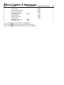
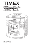
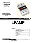
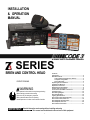
INSTALLATION & OPERATION MANUAL SERIES SIREN AND CONTROL HEAD PATENT PENDING WARNING Sirens produce loud sounds that may damage hearing • Wear hearing protection when testing • Use siren only for emergency response • Roll up windows when siren is operating • Avoid exposure to the siren sound outside of vehicle IMPORTANT: Contents: Introduction...........................................................................2 Standard Features................................................................2 Control Head Configurable (In Vehicle)......................3 Computer Configurable...............................................3 Not Configurable..........................................................5 Unpacking & Pre-installation...............................................7 Installation & Mounting........................................................7 Amplifier Connections.........................................................8 Amplifier Power Distribution...............................................9 Control Head Connections..................................................9 Conventional ArrowStik Connections..............................10 Troubleshooting.................................................................12 Siren Wiring Diagram.........................................................14 Siren Specifications...........................................................15 Lighting Specifications......................................................16 Siren Control Head, Exploded View..................................17 Siren Control Head, Parts List..........................................18 Siren Amplifier, Exploded View.........................................19 Siren Amplifier, Parts List..................................................20 Siren Cables & Harnesses.................................................21 Read all instruction and warnings before installing and using. INSTALLER: This manual must be delivered to the end user of this equipment. 1 Introduction The Siren is a new remote control electronic siren that has been designed to meet the needs of all emergency vehicles. The Siren incorporates many of the popular features of the past and uses microprocessor based circuitry and MOSFET technology. All standard features are available along with many new features that are not available on any other Code 3 siren: Fully Configurable 3-Level Switch, Selectable Tones, Adjustable Backlighting and much more. ! WARNING Sirens are an integral part of an effective audio/visual emergency warning system. However, sirens are only short range secondary warning devices. The use of a siren does not insure that all drivers can or will observe or react to an emergency warning signal, particularly at long distances or when either vehicle is traveling at a high rate of speed. Sirens should only be used in a combination with effective warning lights and never relied upon as a sole warning signal. Never take the right of way for granted. It is your responsibility to be sure you can proceed safely before entering an intersection driving against traffic, or responding at a high rate of speed. The effectiveness of this warning device is highly dependent upon correct mounting and wiring. Read and follow the manufacturer’s instructions before installing this device. The vehicle operator should check the equipment daily to insure that all features of the device operate correctly. To be effective, sirens must produce high sound levels that potentially can inflict hearing damage. Installers should be warned to wear hearing protection, clear bystanders from the area and not to operate the siren indoors during testing. Vehicle operators and occupants should assess their exposure to siren noise and determine what steps, such as consultation with professionals or use of hearing protection should be implemented to protect their hearing. This equipment is intended for use by authorized personnel only. It is the user’s responsibility to understand and obey all laws regarding emergency warning devices. The user should check all applicable city, state and federal laws and regulations. Code 3, Inc., assumes no liability for any loss resulting from the use of this warning device. Proper installation is vital to the performance of the siren and the safe operation of the emergency vehicle. It is important to recognize that the operator of the emergency vehicle is under psychological and physiological stress caused by the emergency situation. The siren system should be installed in such a manner as to: A) Not reduce the acoustical performance of the system, B) Limit as much as practical the noise level in the passenger compartment of the vehicle, C) Place the controls within convenient reach of the operator so that he can operate the system without losing eye contact with the roadway. Emergency warning devices often require high electrical voltages and/or currents. Properly protect and use caution around live electrical connections. Grounding or shorting of electrical connections can cause high current arcing, which can cause personal injury and/or severe vehicle damage, including fire. PROPER INSTALLATION COMBINED WITH OPERATOR TRAINING IN THE PROPER USE OF EMERGENCY WARNING DEVICES IS ESSENTIAL TO INSURE THE SAFETY OF EMERGENCY PERSONNEL AND THE PUBLIC. Standard Features The Siren consists of a remotely mounted siren amplifier with integral lighting control. This is operated by a compact control panel designed to be conveniently mounted near the operator. This model includes the following standard features: - Primary Push-Buttons: WAIL, YELP, ALT TONE (Default Tone for ALT TONE is Hi-Lo 1 but can be configured to use other tones) - Secondary Tones: Multiple User Configurable Tones - MANUAL Push-Button: Default tone is the Manual Wail. - AIR HORN Push-Button: Multiple User Configurable Tones. - 8 Auxiliary Controls: Default to control Auxiliary A through Auxiliary H outputs. Can be configured to control multiple Auxiliary outputs from one Auxiliary push-button. - ArrowStik Control: Muliple User Configurable Flash Patterns (For use with conventional ArrowStik). - Integrated Centrally Controlled ArrowStik - Integrated Code 3 Serial Lightbar Control ! WARNING IMPORTANT WARNINGS TO USERS OF SIRENS: “Wail” and “Yelp” tones are in some cases (such as the state of California) the only recognized siren tones for calling for the right of way. Ancillary tones such as “Air Horn”, “Hi-Lo”, “Hyper-Yelp”, and “Hyper-Lo” in some cases do not provide as high a sound pressure level. It is recommended that these tones be used in a secondary mode to alert motorists to the presence of multiple emergency vehicles or to the momentary shift from the primary tone as an indication of the imminent presence of any emergency vehicle. 2 The following features are standard in the Siren (tones and sequences may differ with user selectable configuration): Control Head Configurable (In Vehicle) Adjustable Backlighting - Backlighting is independent of siren status. The dimming of the lit push-buttons can be adjusted as desired. Press and hold either the LEFT or RIGHT push-buttons for one second. This puts the Control Head into an adjustment mode for the backlighting. Repeatedly press or hold the RIGHT push-button to increase the brightness or the LEFT push-button to decrease the brightness. The brightness can be decreased down to include an off condition. Press the DIM push-button to exit from this adjustment mode. Microphone Volume Adjustment - Press and hold the PTT push-button on the microphone. Then press and hold the Left or Right push-button for one second to enter the volume adjustment mode. Then press the Left or Right arrow push-buttons to decrease or increase the volume, respectively. Once it’s adjusted to the desired volume, press the DIM push-button or release the PTT pushbutton to save the setting. Figure 1 Radio Rebroadcast (RRB) - Broadcast two-way radio reception over siren speakers. These inputs are transformer coupled to prevent loading of the radio. The audio from the 2-way radio is rebroadcast over the siren speakers. The siren tones do not operate when this is activated. All other control functions operate normally. To connect in the signal to be broadcast, simply tie the two signal lines to the RRB1 and RRB2 inputs of the Amplifier (polarity is not an issue). The default setting of the Siren has this option turned off. See the Software User Manual for configuring one of the Auxiliary push-buttons for activating this feature. Once configured to an Auxiliary push-button and that push button is activated, only then can the volume be adjusted by holding down the RIGHT or LEFT push-button for one second. Then pressing the RIGHT or LEFT push-button increases or decreases the volume. Pressing the DIM push-button will save the settings. There is also a time-out but will save the settings before exiting as well. The RRB feature will automatically shutoff to protect from overheating of the Siren. Computer Configurable WAIL Push-Button - This push-button produces the Wail tone when pressed. By default, it also turns on the Level 3 lights but this is configurable to Level 2, Level 1, or no lights. The override tone is also configurable for this feature. Pressing the push-button a second time turns this feature off. Operation of this feature is affected by SirenLock, 3-Level Switch, and Park Kill features. See these sections for details. YELP Push-Button - This push-button produces the Yelp tone when pressed. By default, it also turns on the Level 3 lights but this is configurable to Level 2, Level 1, or no lights. The override tone is also configurable for this feature. Pressing the push-button a second time turns this feature off. Operation of this feature is affected by SirenLock, 3-Level Switch, and Park Kill features. See these sections for details. ALT TONE Push-Button - Both the primary and override tones are configurable for this push-button. This push-button produces the Hi-Lo 1 tone when pressed. It also turns on the Level 3 lights but this is configurable to Level 2, Level 1, or no lights. The override tone is the Hyper-Lo 1 tone. Pressing the push-button a second time turns this feature off. This push-button can be disabled in the configuration software. Operation of this feature is affected by SirenLock, 3-Level Switch, and Park Kill features. See these sections for details. MANUAL Push-Button - In its default configuration, this push-button generates the Manual Wail tone. When pressed, the Manual Wail tone will ramp up to its highest tone and hold. It will hold as long as the MANUAL push-button is held. When the MANUAL push-button is released, the tone will ramp down and return to the previous function. The configuration software can change this to be in Hit-N-Go mode, Scroll mode, or Wail Stop mode. This can also be configured to react differently based on Siren status. Operation of this feature is affected by SirenLock, 3-Level Switch, and Park Kill features. See these sections for details. AIR HORN Push-Button - In its default configuration, the AIR HORN push-button produces the Air Horn 1 tone as long as it is pressed. It will override all other siren tones. The configuration software can set this tone to Air Horn 1 or Air Horn 2. The AIR HORN push-button will work with Park Kill and SirenLock but can be configured to be disabled. See the Siren Configuration Software User Manual for configuration details. 3 Auxiliary A-H Push-Buttons - As configured by the Siren Configuration Software, eight on/off Auxiliary push-buttons are readily accessible for controlling the Auxiliary outputs of the Amplifier. Each Auxiliary push-button can be custom labeled with the supplied label kit. Each push-button is backlighted when activated to alert the operator. The default setting is for each Auxiliary push-button to control the corresponding Auxiliary output of the Amplifier. Auxiliary A through F supplies power to the load through the connector pins labeled A thru F. Auxiliary G and H supplies power with a positive or ground voltage to the load through the connector pins labeled G and H. 3-Level Switch - The Control Head provides a 3-Level switch for changing the emergency warning mode. The 3-Level switch is located in the top left corner of the control head. When the 3-Level switch is switched to the far left position, the unit is off. When the 3-Level switch is in the first position from the left, the level 1 configuration of the lights is turned on. When the 3-Level switch is in the second position from the left, the level 1 & 2 configuration of lights are turned on. When the 3-Level switch is in the third position from the left, the level 1, 2, & 3 configuration of the lights are turned on. Level 1, 2, & 3 activate the LightAlert if supplied. These default settings can be altered using the Siren Configuration Software. The 3-Level switch may be overridden by other push-buttons. If the push-buttons are programmed to a higher level than the position of the 3-Level switch, the push-buttons will take precedence. If the push-buttons are programmed to a lower level than the position of the 3-Level switch, the 3-Level switch will take precedence. The lighting can be set to various levels for the WAIL, YELP, ALT TONE, MANUAL, and AUX push-buttons. Visit these sections in the configuration software to set these preferences. 3-Color Status LED - Three LEDs are visible on the front of the remote siren amplifier. When the 3-Level switch is set to Level 1 the green LED lights. When the siren is set to Level 2 both the green and yellow LEDs light. When the siren is set to Level 3 the green, yellow, and red LEDs light. These LEDs indicate the level of the siren and controls. These Levels are configurable in the Siren Configuration Software User Manual. Hands-Free - Hands-Free mode is directly linked to the Auxiliary push-buttons. By default, the Hands-Free mode is disabled. When an Auxiliary push-button is configured for Hands-Free and that Auxiliary push-button has been turned on, the Hands-Free mode is active but waiting for an initial press of the horn ring to activate the WAIL push-button. A second press of the horn ring will activate the YELP push-button. Pressing the horn ring a third time will activate the ALT TONE push-button. A fourth press of the horn ring will return to the WAIL push-button. This type of scrolling will continue until the user deactivates the Hands-Free Scroll. Pressing the Auxiliary push-button turns off the sound and deactivates the Hands-Free Scroll. Pressing and holding the horn ring will turn off the sound but leave Hands-Free Scroll in the active mode. The Remote input and Manual push-button can also be configured for multiple functions during Hands-Free mode. Please refer to Z3 Siren Configuration Manual for details. See Table on page 6 for factory settings. Horn Ring - The siren accepts either a positive or a ground signal into the Horn Ring input on the Amplifier. The Horn Ring signal is disconnected from the vehicle and connected to the Horn Ring input of the Amplifier. The Horn Relay wire is then run from the Amplifier to the horn of the vehicle. This allows the Horn Ring to execute some of the user selectable functions of the Siren. The Horn Ring can be configured to multiple functions in the Siren Active and Siren Inactive modes of operation. The Horn Ring is set to Scroll in the Hands-Free mode and cannot be changed. Please see the Siren Configuration Software User’s Manual for details. Horn Ring Transfer - The Horn Ring Transfer allows the Horn Ring to be disabled from the vehicle horn and the controls transferred to control other siren tones. The Horn Ring Transfer can be set to occur at Level 1, Level 2, Level 3, or any combination of the three. Remote - The siren accepts either a positive or a ground signal into the Remote Input wire on the Amplifier. This Remote Input wire is usually connected to a user supplied switch. The siren is factory set for a ground signal. The Remote input can be configured to multiple functions in the Siren Active, Siren Inactive, and Hands-Free modes of operation. Please refer to the Siren Configuration Software User’s Manual for details. See Table on page 6 for factory settings. Hit-N-Go - Hit-N-Go only works when a siren tone is active. Once a siren tone is active, Hit-N-Go is activated simply by pressing the Horn Ring (Vehicle Horn Control) or pressing the Remote input. It will go to the Override tone for 8 seconds and then return to the primary tone. The actual tone for the Hit-N-Go depends on which push-button is active. If the WAIL push-button is active then the Hit-N-Go (Override) tone is the Yelp tone. If the YELP push-button is active then the Hit-N-Go tone is the Hyper-Yelp 1 tone, and if the ALT TONE push-button is active then the Hit-N-Go tone is the Hyper-Lo 1 tone. These Override tones are user configurable in the Configuration Software. The siren can also be configured so the MANUAL pushbutton is Hit-N-Go activator. Scroll - Scroll only works when a siren tone is active. Once a siren tone is active, Scroll is activated simply by pressing the Horn Ring (Vehicle Horn Control) or pressing the Remote input. The Scroll Mode will cause the siren to cycle through the WAIL, YELP and ALT TONE push-buttons. For example, if the WAIL push-button is active and the Horn Ring (configured to scroll) is pressed, the YELP push-button will become active. Another press of the Horn Ring will activate the ALT TONE push-button. Another press of the Horn Ring will return to activate the original WAIL push-button. The siren can also be configured so the MANUAL push-button activates the Scroll. NOTE: Pressing and holding the Horn Ring for more than a half second will cause the Siren to generate the Air Horn tone. Scroll On/Off - The Scroll On/Off mode works like the Scroll mode except the Siren will scroll the primary tones through an off state. The Siren will scroll from Wail to Yelp to Alt Tone to off and then back to Wail. The Remote input can be configured to activate Scroll On/Off. NOTE: Pressing 4 and holding the Horn Ring for more than a half second will cause the Siren to generate the Air Horn tone. Load Management - The Load Manager allows setup of three Dropout Voltage Groups by selecting which output to drop out when the vehicle power levels fall below the specified voltage for that group. The default is for no groups to drop out for any reason. See the Siren Configuration Software User Manual for configuration details. LoadMGRTM - This output can control the power supplied to other loads in the vehicle. The power to these loads can be turned off when the driver turns off the vehicle or the voltage of the battery for the vehicle has dropped below a predetermined voltage level. If the Sleep Mode timer is set to a value other than instant, the LoadMGR will turn off after the Sleep Mode timer has expired (see the definition of Sleep Mode). This output is current limited to 1 amp continuous. Connecting the LoadMGR output to an external relay will allow larger external loads to be controlled. The InterClear® wire is used for the LoadMGRTM function. InterClear® and LoadMGRTM cannot function simultaneously. Park Kill - By default, Park Kill puts the siren tones in standby and drops out the Level 3 lighting. Park Kill occurs when the vehicle is shifted into park. Once Park Kill is activated, the siren tones are in standby. The siren tones will remain in standby until the vehicle is shifted into drive and an action occurs such as pressing one of the Control Head push-buttons, changing the position of the 3-Level Switch, or keying the microphone. There are multiple options that can be configured in the configuration software. The Level 3A and siren tones are in standby during Park Kill, and the Auxiliary buttons are not affected by the Park Kill function by default. See the Siren Configuration Software manual for details. The default for the polarity of the Park Kill input is ground (configurable to positive voltage). If the Park Kill input is switched to ground by shifting into park, it will activate the Park Kill functions. InterClear® - Connect to the device or circuit that is to be activated by the InterClear® feature. The InterClear® circuit supplies power to the InterClear® wire, and it is internally current limited at 1 Amp. Power is supplied to the InterClear® wire when Hit-N-Go is activated. Power is also supplied to this wire when the Manual Wail or Wail Stop functions are activated. EU Lock - This function is to meet the requirements of some European Union countries to verify that the Warning Lights for the emergency vehicle are actually operational before allowing the siren to generate tones. This is normally configured to be disabled in the Siren Configuration Software. It can be enabled during configuration of the siren. This feature requires user provided current sense module for the lights. SirenLock - By default, the SirenLock feature is disabled. With SirenLock disabled, the Siren will be in a “Siren Active” mode of operation, and this will disable the “Siren Inactive Function” for the Horn Ring input, Remote input, and Manual push-button. In the Siren Configuration Software, the SirenLock can be changed to allow siren tones when in Level 1, Level 2, and/or in Level 3. Air Horn, Radio Rebroadcast, Manual, and Public Address are unaffected by this feature. LightAlert - By default, the LightAlert feature will produce an audible “beep” on a periodic basis if any lighting is activated including Auxiliary and ArrowStik push-buttons. This is intended to alert the operator that lights are on. The Siren Configuration Software allows this feature to be disabled for selected functions. Sleep Mode - This is by default set to instantly turn off the ration software to turn off after 10, 20, or 30 minutes. Siren system when the vehicle ignition is turned off. This can also be set in the configu- Not Configurable Alarm - This is an input that senses a +12VDC signal even when ignition is turned off. Connect the wire labeled ALARM to a circuit that can supply a +12VDC signal when activated. When a +12VDC signal is seen on this input, a repetitive alarm will sound on the output speakers continuously until the +12VDC signal is removed. For example, this can be used to alarm the police officer when a temperature sensor on a K-9 unit has reached dangerous levels. The alarm will continue until the temperature sensor has returned to safe levels. Automatic Short Circuit Protection - The siren will sense a short circuit on the speaker terminals and automatically go to standby until the fault is removed. Once the fault is removed, the siren will return to normal operation. Instant-On - There is no “ON/OFF” switch. Selecting any siren function, or keying the microphone will activate the selected siren function, assuming the siren is properly installed and the vehicle’s ignition is switched on. Microphone - Pressing the push-button on the microphone will automatically override the current mode of the siren tones and switches to public address mode. Push-To-Talk (PTT) is highest priority and overrides all other siren tones. The microphone is easily plugged into the Control Head with a modular phone plug. This allows the microphone to be unplugged for service or replacement. “Stuck Mic” - When the PTT push-button is pressed, the siren will disable the PTT after 30 seconds of being held. The siren will return to its previous condition even though the push-button is still being held in the on position. This will avoid the situation where the PTT push-button is “stuck” in the on position for extended periods. To continue using the PTT simply release the PTT push-button and press it again. 5 6 LEFT CENTER RIGHT FLASH DIM Level 1 Level 2 Level 3 Group 1 Group 2 Group 3 Overvoltage Protection SirenLock Other Push-Button Settings WAIL YELP ALT TONE MANUAL AIR HORN AUX A AUX B AUX C AUX D AUX E AUX F AUX G AUX H Horn Ring Park Kill LightAlert Sleep Mode CA T13 Remote Load Management ArrowStik 3-Level Switch Override Tone = Yelp Override Tone = Hyper-Yelp 1 Override Tone = Hyper-Lo 1 Hands-Free = Manual Wail Primary Tone = Air Horn 1 Function = Toggle On/Off Function = Toggle On/Off Function = Toggle On/Off Function = Toggle On/Off Function = Toggle On/Off Function = Toggle On/Off Function = 8 Sec Timed Function = Toggle On/Off Primary Tone = Wail Primary Tone = Yelp Primary Tone = Hi-Lo 1 Siren Active = Manual Wail Enable = Always Enabled Function Enabled Function Enabled Function Enabled Function Enabled Function Enabled Function Enabled Function Enabled Function Enabled Auxiliary Push-Buttons = Off Auxiliary Push-Buttons = Off Auxiliary Push-Buttons = Off Polarity = Ground Polarity = Ground Polarity = Ground Activate Auxiliary Switch = None Activate Auxiliary Switch = None Activate Auxiliary Switch = None Setting 4 Activates = Aux A Activates = Aux B Activates = Aux C Activates = Aux D Activates = Aux E Activates = Aux F Activates = Aux G Activates = Aux H Polarity = Positive Polarity = Positive Activates = No Aux Level 3 (Red) Activates = No Aux Level 3 (Red) Activates = No Aux Level 3 (Red) Siren Inactive = Manual Wail, No AUX Activated, Level 3 (Red) 3-Level Switch = Off 3-Level Switch = Off 3-Level Switch = Off Hands-Free = None Siren Active = Hit-N-Go Dropout Delay = 1 Minute Dropout Delay = 1 Minute Dropout Delay = 1 Minute Hands-Free = Scroll Auxiliary Switch Control = No Impact ArrowStik = All Activate ArrowStik = None Activate ArrowStik = None Activate ArrowStik = None Setting 3 Siren Active = Hit-N-Go Siren Control = Siren Standby Auxiliary Switches = All Horn Ring Transfer = Not Activated Horn Ring Transfer = Activated Horn Ring Transfer = Activated Setting 2 Voltage Fault Threshold = 11.50 Volts Voltage Fault Threshold = 11.00 Volts Voltage Fault Threshold = 10.50 Volts Enabled Function Disabled Setting 1 Function = Progressive Function Enabled Function Enabled Function Enabled Conventional ArrowStik = None Function Enabled Function Enabled Function Enabled Function Enabled No Configuration Available Enable = With Horn Ring Transfer 3-Level Switch Control = Level 3A Standby 3-Level Switch = All Sleep Mode = Instant CA T13 = Disabled Enable = With Horn Ring Transfer FACTORY SETTINGS ArrowStik = Off ArrowStik = Off ArrowStik = Off Siren Inactive = None Siren Inactive = None Setting 5 LoadMGR = Off LoadMGR = Off LoadMGR = Off EU Lock = Disabled Setting 6 Unpacking & Pre-installation After unpacking your Siren, carefully inspect the unit and associated parts for any damage that may have been caused in transit. Report any damage to the carrier immediately. Verify all components have been delivered. The box should contain the Siren Control Head, Amplifier, cable/harness bag, microphone, hardware bag, legend set and user manuals bag. Installation & Mounting The Siren Control Head is made to mount directly in the console of most leading manufacturers as seen in Fig. 3 shown below. It may also be Figure 2 mounted above the dash, below the dash or on the transmission tunnel using the mounting hardware supplied (see Fig. 2 above). Also reference page 15 and 16 for description of components and Code 3 part numbers. Ease of operation and convenience to the operator should be the prime consideration when mounting the siren and controls. When choosing a mounting location the user must consider the deployment area for the air bag of the vehicle and other factors which might impact the safety of the vehicle occupants. NOTE: Setups and adjustments will be made in steps that may require access to the rear area of the unit. Plan the installation and wiring accordingly. Figure 3 ! WARNING All devices should be mounted in accordance with the manufacturer’s instructions and securely fastened to vehicle elements of sufficient strength to withstand the forces applied to the device. Ease of operation and convenience to the operator should be the prime consideration when mounting the siren and controls. Adjust the mounting angle to allow maximum operator visibility. Do not mount the Control Head Module in a location that will obstruct the drivers view. Mount the microphone clip in a convenient location to allow the operator easy access. Devices should be mounted only in locations that conform to their SAE identification code as described in SAE Standard J1849. For example, electronics designed for interior mounting should not be placed underhood, etc. Controls should be placed within convenient reach* of the driver or if intended for two person operation the driver and/or passenger. In some vehicles, multiple control switches and/or using methods such as “horn ring transfer” which utilizes the vehicle horn switch to toggle between siren tones may be necessary for convenient operation from two positions. *Convenient reach is defined as the ability of the operator of the siren system to manipulate the controls from their normal driving/riding position without excessive movement away from the seat back or loss of eye contact with the roadway. 7 Amplifier Connections All Amplifier connections are made on one side of the Amplifier as seen in figure 4. See wiring diagram on page 13. All Amplifier connections are quick disconnect requiring no tools. Figure 4 ! WARNING Larger wires and tight connections will provide longer service life for components. For high current wires it is highly recommended that terminal blocks or soldered connections be used with shrink tubing to protect the connections. Do not use insulation displacement connectors (e.g. 3M® Scotchlock type connectors). Route wiring using grommets and sealant when passing through compartment walls. Minimize the number of splices to reduce voltage drop. High ambient temperatures (e.g. under-hood) will significantly reduce the current carrying capacity of wires, fuses, and circuit breakers. Use “SXL” type wire in engine compartment. All wiring should conform to the minimum wire size and other recommendations of the manufacturer and be protected from moving parts and hot surfaces. Looms, grommets, cable ties, and similar installation hardware should be used to anchor and protect all wiring. Particular attention should be paid to the location and method of making electrical connections and splices to protect these points from corrosion and loss of conductivity. Ground terminations should only be made to substantial chassis components, preferably directly to the vehicle battery. The user should install a fuse sized to approximately 125% of the maximum Amp capacity in the supply line and each switched circuit to protect against short circuits. For example, a 30 Amp fuse should carry a maximum of 24 Amps. DO NOT USE 1/4” DIAMETER GLASS FUSES AS THEY ARE NOT SUITABLE FOR CONTINUOUS DUTY IN SIZES ABOVE 15 AMPS. Circuit breakers are very sensitive to high temperatures and will “false trip” when mounted in hot environments or operated close to their capacity. Fuses or circuit breakers should be located as close to the power takeoff points as possible and properly sized to protect the wiring and devices. 8 WARNING ! Connection of a 58 watt speaker to the siren amplifier will cause the speaker to burn out, and will void the speaker warranty! Amplifier Power Distribution The Level 1, 2, 3A and 3B outputs can supply a maximum of 15 Amps each or a combined total of 50 Amps. Each Level has a 20 Amp fuse installed inside the Amplifier. Fuses may be accessed through the panel on top of the Amplifier. The Auxiliary outputs A, B, C and D can supply a maximum of 5 amps each. Auxiliary outputs E, F, G and H can supply a maximum of 10 amps each. The combined total for all Auxiliary outputs is 50 Amps. Auxiliary outputs A, B, C and D have 7.5 amp fuses and Auxiliary outputs E, F, G and H have 15 amp fuses. Fuses may be accessed through the panel on top of the Amplifier. WARNING ! Any electronic device may create or be affected by electromagnetic interference. After installation of any electronic device, operate all equipment simultaneously to insure that operation is free of interference. Control Head Connections The connection from the Control Head to the remote Amplifier is made using a standard CAT-5 cable (P/N T56649) connected to the port labeled SIREN AMP on the back of the Control Head. This cable is found in the Harness & Cable Bag P/N T56641. See figure 5 below. In addition, the microphone P/N T11856 connects to the Control Head port labeled PA MIC. The microphone also uses a Microphone Hanger Bracket (P/N T00631) that mounts to the dash of the vehicle. Figure 5 WARNING ! Utilizing non-factory specified screws and/or mounting brackets and/or the improper number of screws may result in failure of the mounting system and severe damage to the vehicle as well as loss of warranty coverage on the equipment. 9 Conventional ArrowStik Connections CC ArrowStik Connection The Siren can connect directly to any Code 3 Centrally Controlled (CC) Lightbar ArrowStik and some non-Code3 CC Lightbar ArrowStiks using Code 3 harness P/N T56629 (see figure 8). This harness is found in the Harness & Cable Bag P/N T56641. Refer to the wiring diagram on page 13. Conventional ArrowStik Connection The Siren can also connect directly to a conventional ArrowStik or both at the same time using Code 3 harness P/N T56631 (see figures 6 & 7). Refer to the wiring diagram on page 13. If a conventional ArrowStik is desired see the Siren Configuration Software Manual for details regarding flash pattern selection. The 9 wire harness can be connected to drive an 8, 6, or 5 head ArrowStik. The Siren is compatible with some non-Code 3 ArrowStik products. The Siren conventional ArrowStik outputs provide a current sink (ground) signal when active. Each output is rated for an absolute maximum of 5 amps. See the wiring diagram on page 13 and the install manual for your ArrowStik product for wiring details. 8 HEAD HARNESS CONNECTIONS When viewing the vehicle from the rear, the ArrowStik harness is connected in the following order from Driver side to Passenger side: Blue, Yellow, Gray, Green, Violet, Tan, Orange, Brown. The Right Arrow travels from Blue to Brown. The Left Arrow travels from Brown to Blue. 6 HEAD HARNESS CONNECTIONS When viewing the vehicle from the rear, the ArrowStik harness is connected in the following order from Driver side to Passenger side: Yellow, Gray, Green, Violet, Tan, Orange. The Right Arrow travels from Yellow to Orange. The Left Arrow travels from Orange to Yellow. If the Siren ArrowStik function is configured for ArrowStik End Flash, the Blue and Brown wires will attach to the two end light heads. 5 HEAD HARNESS CONNECTIONS When viewing the vehicle from the rear, the ArrowStik harness is connected in the following order from Driver side to Passenger side: Yellow, Gray, Violet, Tan, Orange. The Right Arrow travels from Yellow to Orange. The Left Arrow travels from Orange to Yellow. If the Siren ArrowStik function is configured for ArrowStik End Flash, the Blue and Brown wires will attach to the two end light heads. DIM Control The Siren DIM function supplies +12VDC output when active. This output is compatible with the dimming input of older Code 3 ArrowStik products. It is not used with newer Code 3 ArrowStik products. This output can supply an absolute maximum of 1.5 amps. Programming The Siren will come from the factory set to control a CC ArrowStik. For details about ArrowStik pattern selection for Code 3 CC Lightbars, refer to the Lightbar user manual. For an conventional ArrowStik, refer to the Siren Configuration Software Manual. 10 NON-CC WIRING CONNECTIONS Figure 6 Figure 7 CC WIRING CONNECTION Figure 8 11 Troubleshooting (Refer to wiring diagram on page 13.) PROBLEM PROBABLE CAUSE REMEDY NO SIREN OUTPUT A. PARK KILL ACTIVATED B. SIRENLOCK ENGAGED C. SHORTED SPEAKER OR SPEAKER WIRES. SIREN IN OVER CURRENT PROTECTION MODE. D. OVERVOLTAGE > 15V A. SHIFT VEHICLE OUT OF PARK. B. SELECT PROPER SIRENLOCK LEVEL. C. CHECK CONNECTIONS D. CHECK VEHICLE BATTERY EXTERNAL 20A FUSE BLOWS A. AMPLIFIER POWER WIRES REVERSED POLARITY A. CHECK POLARITY B. REPLACE SPEAKER(S) NO OUTPUT FROM SPEAKER, TONES HEARD INSIDE AMPLIFIER MODULE A. SPEAKER NOT CONNECTED/ OPEN CIRCUIT IN SPEAKER WIRING B. DEFECTIVE SPEAKERS A. CHECK SPEAKER WIRING B. REPLACE SPEAKER(S) SIREN TONES VOLUME TOO LOW/GARBLED A. LOW VOLTAGE TO SIREN AMPLIFIER B. HIGH RESISTANCE IN WIRING/DEFECTIVE SPEAKER C. SPEAKERS PHASED IMPROPERLY A. CHECK WIRING FOR BAD CONNECTIONS/CHECK VEHICLE CHARGING SYSTEM. B. CHECK SPEAKER(S) WIRING/REPLACE SPEAKER(S). C. REFER TO PAGE 3 FOR PROPER PHASING (200W OPTION) HIGH RATE OF SPEAKER FAILURE A. HIGH VOLTAGE TO SIREN B. 58 WATT SPEAKER CONNECTED TO 100 WATT TAP. 58 WATT NOT ALLOWED. A. CHECK VEHICLE CHARGING SYSTEM. B. USE CORRECT SPEAKER. SIREN CONTINUES TO OPERATE FOR 7 SECONDS AFTER MANUAL BUTTON/HORN RING IS RELEASED A. “HIT-N-GO’ FEATURE ENGAGED. NORMAL OPERATION INTERCLEAR WILL NOT POWER AUXILIARY A. THERE IS A SHORT IN THE WIRING, OR DEVICES THE LOAD IS GREATER THAN 1 AMP. A. CHECK FOR SHORTS. INSTALL INTERCLEAR BOOSTER KIT (PART #INTBS) P. A. VOLUME LOW OR NO P. A. AT ALL. A. INCREASE P.A. VOLUME. B. MICROPHONE NOT COMPLETELY PLUGGED IN. C. DEFECTIVE MICROPHONE D. COMMON MICROPHONE CIRCUIT NOT PROPERLY WIRED. E. INCORRECT MICROPHONE. A. REFER TO SETUP AND ADJUSTMENT SECTION B. PLUG MICROPHONE IN SECURELY C. REPLACE MICROPHONE D. CHECK WIRING E. CALL CODE 3 FOR LIST OF ADAPTABLE MICROPHONES. RRB VOLUME LOW, OR NO RRB AT ALL. A. INCREASE RADIO REBROADCAST VOLUME. B. RRB WIRES NOT CONNECTED TO TWOWAY RADIO EXTERNAL SPEAKER. A. REFER TO SETUP AND ADJUSTMENT SECTION. B. CHECK RRB CONNECTIONS. SIREN SOUNDS BY ITSELF A. REMOTE SWITCH (HORN RING) WIRING FROM TERMINAL REMOTE SHORTING TO POSITIVE OR TO GROUND (EARTH). A. CHECK WIRING FOR ANY SHORTING. SIREN RUNS PROPERLY BUT SHUTS DOWN WHILE RUNNING, THEN STARTS RUNNING AGAIN AFTER A FEW MINUTES. A. VEHICLE CIRCUIT BREAKERS NOT RATED PROPERLY, AND ARE OVERHEATING, OR ARE NOT FUNCTIONING PROPERLY. A. REFER TO SPECIFICATIONS SECTION, PAGE 17. USE A BREAKER RATED AT 1.25 TIMES THE AMPERAGE OF THE EXPECTED LOAD CURRENT. WHEN POWERED THERE IS A 5 SECOND A. CONTROL HEAD HAS FAILED TO COMPAUSE AND THEN A FLASH AND BEEP MUNICATE WITH THE AMPLIFIER. EVERY 2 SECONDS CONTINUOUSLY WITH- B. CONFIGURATION LOAD FAILURE. OUT STOPPING. 12 A. CHECK CONNECTION OF CAT-5 CABLE FROM CONTROL HEAD TO AMPLIFIER. B. RESET POWER. C. RELOAD AMPLIFIER CONFIGURATION. D. CONTACT CUSTOMER SERVICE. Troubleshooting Continued (Refer to wiring diagram on page 13.) PROBLEM PROBABLE CAUSE REMEDY THE GREEN, AMBER, AND/OR RED LEDS FLASH RAPIDLY AND CONTINUOUSLY. A. ONE OR MORE OF THE 3-LEVEL FUSES HAVE BLOWN IN THE AMPLIFIER. B. 12V IS NOT BEING SUPPLIED TO THE 12V 3L INPUT. C. LEVEL OUTPUT SHORTED A. REPLACE THE FUSE(S) IN THE AMPLIFIER. B. CHECK INPUT POWER CONNECTION. C. CHECK CONNECTION TO LOAD ANY OF THE ACTIVE AUX A-F PUSHBUTTONS FLASH RAPIDLY AND CONTINUOUSLY. A. ONE OR MORE OF THE AUX A-F FUSES HAVE BLOWN IN THE AMPLIFIER. B. 12V IS NOT BEING SUPPLIED TO THE AUX A-F OUTPUTS. A. REPLACE THE FUSE(S) IN THE AMPLIFIER. B. CHECK HARNESS CONNECTION BETWEEN THE AMPLIFIER AND THE AUXILIARY DEVICES. IF IN LEVEL 3 AND THE VEHICLE IS IN PARK, THE RED LEVEL INDICATOR ON THE CONTROL HEAD IS BLINKING AT A SLOW RATE. A. THIS IS NORMAL. THIS IS COMMUNICATING THAT THE LEVEL 3A OR THE LEVEL 3B LIGHTS ARE IN STANDBY (TURNED OFF). B. LOAD MANAGER HAS SENSED LOW INPUT AND TURNED OFF 3A OR 3B. A. PUT THE VEHICLE BACK INTO DRIVE. B. CHECK VEHICLE BATTERY VOLTAGE. PA ONLY FUNCTIONS FOR 30 SECONDS BEFORE TURNING OFF. A. THIS IS NORMAL. THE PA IS TURNED OFF AFTER 30 SECONDS TO AVOID THE STUCK MIC POSSIBILITY. A. SIMPLY RELEASE THE PTT BUTTON AND PRESS AGAIN FOR ANOTHER 30 SECONDS OF BROADCAST ABILITY. RRB SHUTS OFF AFTER EXTENDED USE. A. THIS IS NORMAL. THE RRB SHUTS OFF AFTER AN EXTENDED PERIOD WHEN THE EQUIPMENT STARTS TO OVERHEAT. THIS IS TO AVOID DAMAGE TO THE COMPONENTS IN THE AMPLIFIER. A. ALLOW THE AMPLIFIER A FEW MINUTES TO COOL DOWN. 13 Siren Wiring Diagram 14 Siren Specifications Siren Section: Input Voltage 10 to 16 VDC and ground - 12V units (Note: Operation of 12V units above 15 VDC for an extended period of time may result in speaker damage.) Operating Current 100W: 8 Amps @ 13.6V with 11-ohm load (100 Watt Speaker) - 12V units 200W: 14 Amps @ 13.6V with 5.5-ohm load (2-100 Watt Speakers) - 12V units (NOTE: There is no 58 Watt speaker connection available.) Standby Current Ignition On < 10mA Ignition Off < 1mA Cycle Rate Wail - 11 cycles/minute Yelp - 200 cycles/minute ~ 66 Vpp Voltage Output Audio Section: Audio Response 3 dB down points - 500 to 3000 Hz 1000 Hz, 0 dB reference 15 Lighting Specifications Warning Light Control: 3-Level Switch, 4 Outputs, 50 Amps. maximum combined total Level 1 & 2: 15 Amp Maximum Each Level 25 Amp Maximum Total Green (1) & Yellow (2) LED Indication Level 3A & 3B: 15 Amp Maximum Each Level 25 Amp Maximum Total Red (3) LED Indication AUX A thru D: 5 Amp Maximum Each Aux 20 Amp Maximum Total AUX E thru H: 10 Amp Maximum Each Aux 30 Amp Maximum Total ArrowStik: 8 Output (not internally fused), Ground Switching, 5A Per Output DIM Output, +12VDC, 1.5A Internally Protected System - Weight: Amplifier 4.2 lbs (1.9 Kg) Control Head & Microphone 1.1 lbs (0.5 Kg) Boxed Unit 9.5 lbs (4.3 Kg) Size: Amplifier 9.750”L x 6.832”W x 3.936”H Control Head 6.80”L x 3.30”H x 1.07”D (Switch will increase depth dimension to 1.95”D.) Temperature: -22F thru +149F (-30C thru +65C) SAE Equipment Type EVS1 16 17 Siren Control Head, Exploded View Siren Control Head, Parts List Ref No. Description Purchasable Part No. Internal Part No. (Not For Sale)Qty. 1 8-32 X 1/4” Hex Head MS T10385 2 2 Control Head Mounting Bracket T10924 2 3 1/4”-20 X 3/8” Hex Head MS T10912 2 4 Circuit Board Support, Nylon T11862 5 5Sheet Metal Base PlateT152871 6 .187 OD 4-40 Standoff T10890 2 7 4 Position Switch Assembly T56634 1 8 4-40 X 3/8” Phil Pan HD T06937 2 9 Control HD PCB T11858 1 10Molded KeypadT152851 11Molded Control HousingT152811 12Moulded Switch KnobT152861 13Part of Amp Box Wiring LabelT118631 To order a complete Siren Control Head, order part number S39284M. (The Siren Control Head will not function without a Siren Amplifier.) To order a complete Siren Cable & Harness bag, order part number T56641. To order a complete Siren Manuals & Legends bag, order part number S38284M. 18 Siren Amplifier, Exploded View 19 Siren Amplifier, Parts List Ref No. Description Purchasable Part No. Internal Part No. (Not For Sale) Qty. 1 Amplifier E Tray T15305 All Amplifier Components 1 2 Amplifier PCB T11851 Are Purchasable 1 3 #6-32 X .375” Phil Pan HD MS T04250 1 4 #6-32 X 1.875” Hex MF Stdoff T15326 2 5 Outputs & Dim Int Harness T56632 3 6 Light Board PCB T11854 1 7I2C Comm CableT566231 8#6-32 X .250 Phil Pan HD MST070773 9 Amplifier Cover T15307 1 10 Amplifier Fuse Cover T15310 1 11 #8-32 X .250 Phil Pan HD TRS T09751 2 12 Warning Label T09937 1 13Wiring Label Fuse MapT118611 14 Wiring Label Amp Box Top T11863 1 15#6-32 X 2.250 Phil Pan HD MS T153283 16Washer, Int Tooth #6T001501 17#6-32 X 1.500 Phil Pan HD MS T013321 18Wiring Label, Terminal SideT118631 To order a complete To order a complete To order a complete Siren Amplifier, order part number S39285M. Siren Cable & Harness bag, order part number T56641. Siren Manuals & Legends bag, order part number S38284M. 20 Siren Cables & Harnesses Ref No. Description Purchasable Part No. Internal Part No. (Not For Sale) Qty. 1Light Board Power HarnessT566271 2Aux A-D HarnessT566281 3 L/R Arrow, Dim, Flash Harness T56629 1 4 Level 1, 2, 3A, 3B Harness T56630 1 5 Outputs & Dim Ext. Harness T56631 1 6 CAT5 Cable Min 20 FT T56649 1 7Input/Output HarnessT566361 8 Amplifier Power Harness T56637 1 9 Aux E-H Harness T56638 1 10 USB A Male to A Male Cable T56639 1 11Mic w/Modular PlugT118561 To order a complete To order a complete To order a complete Siren Amplifier, order part number S39285M. Siren Cable & Harness bag, order part number T56641. Siren Manuals & Legends bag, order part number S38284M. 21 NOTES 22 NOTES 23 WARRANTY Code 3®, Inc.’s emergency devices are tested and found to be operational at the time of manufacture. Provided they are installed and operated in accordance with manufacturer’s recommendations, Code 3®, Inc. guarantees all parts and components except the lamps to a period of 1 year, LED Lighthead modules to a period of 5 years (unless otherwise expressed) from the date of purchase or delivery, whichever is later. Units demonstrated to be defective within the warranty period will be repaired or replaced at the factory service center at no cost. Use of lamp or other electrical load of a wattage higher than installed or recommended by the factory, or use of inappropriate or inadequate wiring or circuit protection causes this warranty to become void. Failure or destruction of the product resulting from abuse or unusual use and/or accidents is not covered by this warranty. Code 3®, Inc. shall in no way be liable for other damages including consequential, indirect or special damages whether loss is due to negligence or breach of warranty. CODE 3®, INC. MAKES NO OTHER EXPRESS OR IMPLIED WARRANTY INCLUDING, WITHOUT LIMITATION, WARRANTIES OF FITNESS OR MERCHANTABILITY, WITH RESPECT TO THIS PRODUCT. PRODUCT RETURNS If a product must be returned for repair or replacement*, please contact our factory to obtain a Return Goods Authorization Number (RGA number) before you ship the product to Code 3®, Inc. Write the RGA number clearly on the package near the mailing label. Be sure you use sufficient packing materials to avoid damage to the product being returned while in transit. *Code 3®, Inc. reserves the right to repair or replace at its discretion. Code 3®, Inc. assumes no responsibility or liability for expenses incurred for the removal and /or reinstallation of products requiring service and/or repair; nor for the packaging, handling, and shipping: nor for the handling of products returned to sender after the service has been rendered. Problems or Questions? Call The Technical Assistance HOTLINE - (314) 996-2800 Code 3, Inc. 10986 N. Warson Road St. Louis, Missouri 63114-2029—USA Ph. (314) 996-2800 Fax (314) 426-1337 www.code3pse.com Code 3,® Inc., a subsidiary of Public Safety Equipment, Inc. Code 3 is a registered trademark of Code 3, Inc. Revision 1, 15/03 - Instruction Book Part No. T56643 ©2011 Public Safety Equipment, Inc. Printed in USA 24