1
TM-U325D/U325PD
User’s Manual
400665704
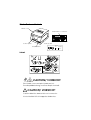
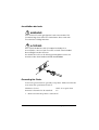
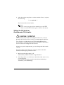
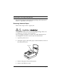
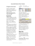
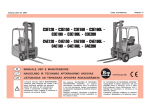
Printer Parts and Labels
Printer cover
Serial interface connector
14
EPS
ON
25
1
1
6
FE
ED
RE
LE
AS
E
1
RE
OU
CE
T
IPT
ER
RO
VA
R
LID
ATIO
PO
WE
N
R
2
3
13
6
1
2
3
1
Parallel interface connector
Control panel
Control panel
On/Off switch
FEED
RELEASE
RECEIPT
VALIDATION
OUT
ERROR
POWER
EPSON/U325 Printer - File: PRNTR_8.e
W. Swanlund
REV> 14Octobe
Labels
1
3
2
5 CUT
4
2 SET
1 3
6 CLOSE THE
PRINTER COVER
CAUTION/ VORSICHT:
Print head cover and print head are hot.
Druckkopfabdeckung und Druckkopf sind heiß.
CAUTION/ VORSICHT:
Caution label for drawer kick-out connector.
Vorsichtsetikett für Schnappsteckerbuchse.
All rights reserved. No part of this publication may be reproduced, stored in a retrieval system,
or transmitted in any form or by any means, electronic, mechanical, photocopying, recording,
or otherwise, without the prior written permission of Seiko Epson Corporation. No patent
liability is assumed with respect to the use of the information contained herein. While every
precaution has been taken in the preparation of this book, Seiko Epson Corporation assumes no
responsibility for errors or omissions. Neither is any liability assumed for damages resulting
from the use of the information contained herein.
Neither Seiko Epson Corporation nor its affiliates shall be liable to the purchaser of this product
or third parties for damages, losses, costs, or expenses incurred by purchaser or third parties as
a result of: accident, misuse, or abuse of this product or unauthorized modifications, repairs, or
alterations to this product, or (excluding the U.S.) failure to strictly comply with Seiko Epson
Corporation’s operating and maintenance instructions.
Seiko Epson Corporation shall not be liable against any damages or problems arising from the
use of any options or any consumable products other than those designated as Original Epson
Products or Epson Approved Products by Seiko Epson Corporation.
EPSON and ESC/POS are registered trademarks of Seiko Epson Corporation.
NOTICE: The contents of this manual are subject to change without notice.
Copyright © 1996, 1999 by Seiko Epson Corporation, Nagano, Japan.
i
EMC and Safety Standards Applied
Product Name: TM-U325D/TM-U325PD
Model Name: M133A
The following standards are applied only to the printers that are so labeled. (EMC is tested
using Seiko Epson’s AC Adapter.)
Europe:
North America:
Oceania:
CE marking
Safety: EN 60950
EMI: FCC/ICES-003 Class A
Safety: UL 1950/CSA C22.2 No. 950
EMC: AS/NZS CISPR22 Class B
WARNING
The connection of a non-shielded printer interface cable to this printer will invalidate the EMC
standards of this device.
You are cautioned that changes or modifications not expressly approved by SEIKO EPSON
Corporation could void your authority to operate the equipment.
CE Marking
The printer conforms to the following Directives and Norms:
Directive 89/336/EEC
EN 55022 Class B
EN 55024
IEC 61000-4-2
IEC 61000-4-3
IEC 61000-4-4
IEC 61000-4-5
IEC 61000-4-6
IEC 61000-4-11
FCC Compliance Statement
For American Users
This equipment has been tested and found to comply with the limits for a Class A digital
device, pursuant to Part 15 of the FCC Rules. These limits are designed to provide reasonable
protection against harmful interference when the equipment is operated in a commercial
environment.
This equipment generates, uses, and can radiate radio frequency energy and, if not installed
and used in accordance with the instruction manual, may cause harmful interference to radio
communications. Operation of this equipment in a residential area is likely to cause harmful
interference, in which case the user will be required to correct the interference at his own
expense.
For Canadian Users
This Class A digital apparatus complies with Canadian ICES-003.
Cet appareil numérique de la classe A est conforme à la norme NMB-003 du Canada.
GEREÄUSCHPEGEL
Gemäß der Dritten Verordnung zum Gerätesicherheitsgesetz (MaschinenlärminformationsVerordnung-3. GSGV) ist der arbeitsplatzbezogene Geräusch-Emissionswert kleiner als 70
dB(A) (basierend auf ISO 7779).
ii
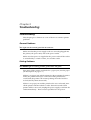
About This Manual
Setting Up and Using
❏
Chapter 1 contains information on unpacking the printer, setting it up, attaching
the paper roll near-end sensor, and setting the DIP switches.
❏
Chapter 2 contains information on using the printer.
❏
Chapter 3 contains troubleshooting information.
Reference
❏
Chapter 4 contains specifications and character code tables.
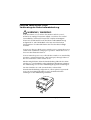
Warnings, Cautions, and Notes
WARNING / WARNUNG:
Warnings must be followed carefully to avoid serious bodily
injury.
Warnhinweise müssen sorgfältig befolgt werden, um Unfälle
mit möglicherweise schweren Verletzungen zu vermeiden.
CAUTION / VORSICHT:
Cautions must be observed to avoid minor injury to yourself or
damage to your equipment.
Vorsichtshinweise müssen sorgfältig befolgt werden, um
Unfälle mit der Gefahr leichter Verletzungen oder Schäden
am Gerät zu vermeiden.
Note:
Notes have important information and useful tips on the operation of your
printer.
iii
Introduction
Features
The TM-U325D and TM-U325PD are high-quality POS printers that can print a
multiple-line validation and on receipt paper (paper roll). The printer has the
following features:
❏
Easily changeable interface specifications for serial or parallel by exchanging the
interface board.
❏
Excellent reliability (long life) and good operability (drop-in paper loading).
❏
Multiple-line validation printing (possible to print a maximum of 9 lines).
❏
Compact and light in weight.
❏
High-speed printing through logic-seeking control.
❏
Excellent reliability and long life due to adoption of stepping motor, both for
moving the carriage and for paper feeding.
❏
Flexible line space setting permits printing in accordance with any user-defined
format.
❏
Conforms with ESC/POS; excellent universality of control.
❏
Built-in drawer kick-out interface provides capability to drive two drawers.
❏
Selectable character fonts (7 × 9 and 9 × 9).
❏
Semi-automatic paper loading capability.
❏
AC adapter provides compact power supply.
❏
Automatic status back (ASB) function that automatically transmits changes in
printer status.
Accessories
❏
AC adapter
❏
EPSON ribbon cassette, ERC-38
Options
❏
EPSON power supply unit, PS-180
❏
Printer fastening tape (Model No. DF-10)
iv
Chapter 1
Setting Up the Printer
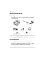
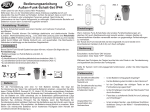
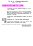
Unpacking
The illustration below shows the items included for the standard
specification printer.
EPS
ON
FEE
D
REL
EAS
E
REC
OU
T EIPT
ERR
VAL
OR
IDA
POW
TIO
N
ER
Power supply
*1
Printer
Ribbon cassette
Spacers for the paper roll
near-end sensor 2 pcs
Paper roll
Manual
Power switch cover
(*1) The power cord may not be included in the package. If it is not, make sure to use a
power cord that complies with the safety standards.
If any item is damaged, please contact your dealer for assistance.
Selecting a Location
Place the printer on a surface that is as horizontal as possible. Make
sure that the printer does not tilt more than 15 degrees.
The printer should be installed so that it does not move or vibrate
during paper cutting or the drawer kick-out operation.
Fastening tape is available as an option.
Setting Up the Printer 1–1
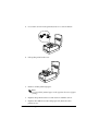
Adjusting the Paper Roll Near-End Sensor
Notes:
Use paper rolls with an inner core diameter of 10.5 to 12.5 mm so
that the sensor detects the remaining paper correctly.
When the last portion of a paper roll bears red markings, the
marking is sometimes an adhesive that pulls the entire paper roll up.
In this case, the sensor may not detect the remaining paper correctly.
If a paper roll easily becomes loose because of the quality of the paper
or other factors, incorrect detection of the paper end may result.
1.
Make sure that the power supply is disconnected from the printer.
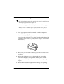
2. Two spacers are included. See the illustration below and decide
whether or not you want to use them. Use them if you want the
near-end sensor to be triggered when distance A is 3 to 4 mm;
otherwise it will be triggered when distance A is approximately
6 mm.
Distance A
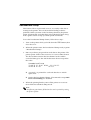
3. Secure the paper roll near-end sensor (and spacers) with two
screws. When you insert the spacers, be sure you set the
spacers in the direction shown in the illustration.
1–2 Setting Up the Printer
Spacers
Paper roll
near-end sensor
4. Check to be sure that the detecting lever moves freely.
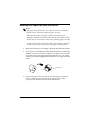
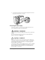
Connecting the Cables and Grounding the Printer
You can connect up to three cables and a grounding wire to the
printer. They all connect to the connector panel on the bottom of
the printer, which is shown below:
Power supply
Drawer kick-out
Grounding screws
Interface
Notes:
There is a caution label beside the drawer kick-out connector.
Depending on the interface installed, the interface connector on your
printer may look different from the one illustrated.
Before connecting any of the cables, make sure that both the printer
and the computer are turned off.
Setting Up the Printer 1–3
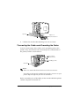
Connecting the Computer
1. Plug the cable into the connector on the printer and tighten the
screws on both sides of the cable connector, as shown.
2. Connect the other end of the cable to the connector on your
computer.
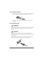
Connecting the Drawer
WARNING:
Use a drawer that matches the printer specification. Using an
improper drawer may damage the drawer as well as the
printer.
CAUTION:
Do not connect a telephone line to the drawer kick-out
connector; otherwise the printer and the telephone line may
be damaged.
Plug the drawer cable into the drawer kick-out connector on the
bottom of the printer next to the power supply connector.
1–4 Setting Up the Printer
Anschließen der Lade
WARNUNG:
Eine für den Drucker geeignete Lade verwenden. Bei
Verwendung einer falschen Lade kann diese oder der
Drucker beschädigt werden.
ACHTUNG:
Kein Telefonkabel an die Schnappsteckerbuchse
anschließen, da sonst der Drucker und die Telefonkabel
beschädigt werden können.
Das Kabel der Lade an die Schnappsteckerbuchse unten am
Drucker neben dem Netßzanschluß anschließen.
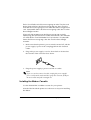
Grounding the Printer
You need a ground wire to ground your printer. Make sure that the
wire meets the specifications below.
Thickness of wire:
Diameter of terminal to be attached:
AWG 18 or equivalent
3.2
1. Make sure that the printer is turned off.
Setting Up the Printer 1–5
2. Connect the ground wire to the printer using the FG screw on
the bottom of the printer, as shown.
Connecting the Power Supply
This printer requires an external power supply. Be sure to use a
power supply that matches the specifications.
WARNING / WARNUNG:
Using an incorrect power supply may cause fire or electrical
shock.
Bei Verwendung der falschen Stromversorgung besteht
Brand- oder Stromschlaggefahr.
CAUTION / VORSICHT:
When connecting or disconnecting the power supply from
the printer, make sure that the power supply is not plugged
into an electrical outlet; otherwise you may damage the
power supply or the printer.
If the power supply’s rated voltage and your outlet’s voltage
do not match, contact your dealer for assistance. Do not
plug in the power cord. Otherwise you may damage the
power supply or the printer.
1–6 Setting Up the Printer
Beim Anschließen der Stromversorgung an den Drucker und
beim Herausziehen der Stromversorgung aus dem Drucker
darf die Stromversorgung nicht in eine Steckdose eingesteckt
sein. Andernfalls kann die Stromversorgung oder der Drucker
beschädigt werden.
Wenn die Nennspannung der Stromversorgung und die
Spannung der Steckdose nicht übereinstimmen, den Händler
um Hilfe bitten. Das Netzkabel nicht einstecken. Andernfalls
kann die Stromversorgung oder der Drucker beschädigt
werden.
1. Make sure that the printer’s power switch is turned off, and the
power supply’s power cord is unplugged from the electrical
outlet.
2. Plug in the power supply’s cord as shown below. Notice that
the flat side of the connector faces down.
3. Plug the power supply’s power cord into an outlet.
Note:
If you ever need to remove the cable, unplug the power supply’s
power cord from the outlet and then grasp the connector firmly at
the arrow mark and pull it straight out.
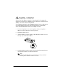
Installing the Ribbon Cassette
Use the EPSON ERC-38 ribbon cassette for your printer.
Note the label inside the printer cover that can assist you in installing
the ribbon.
Setting Up the Printer 1–7
CAUTION / VORSICHT:
Never turn the ribbon cassette’s feed knob in the opposite
direction of the arrow marked on the cassette; otherwise the
ribbon cassette may be damaged.
Den Transportknopf an der Farbbandkassette nur in die durch
den Pfeil gekennzeichnete Richtung drehen. Andernfalls
kann die Farbbandkassette beschädigt werden.
1. Be sure the printer is not receiving data when you replace a
ribbon cassette; otherwise data may be lost.
2. Open the printer cover.
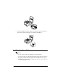
3. Turn the ribbon cassette’s knob in the direction of the arrow, to
take up any slack in the ribbon.
4. Insert the ribbon in the position shown in the illustration below
and push the ribbon cassette until it clicks.
Note:
Make sure that the ribbon is installed between the print head
and the platen without wrinkles or creases.
1–8 Setting Up the Printer
EP
SO
N
ED
FE
E
AS
LE
RE
N
IO
AT
LID
T
IP VA
R
CE
WE
RE T
PO
OU
R
RO
ER
5.
Turn the ribbon cassette’s knob 5 or 6 times in the direction of
the arrow again, to take up any slack in the ribbon.
EP
SO
N
ED
FE
E
AS
LE
RE
ER
N
IO
AT
LID
T
IP VA
R
CE
WE
RE T
PO
OU
R
RO
Installing the Paper Roll
Notes:
Be sure to use a paper roll that meets the specifications.
Do not use paper rolls that have the paper glued to the core because
the printer cannot detect the paper end correctly. However, if you
will stop the printing using the paper roll near-end sensor, you can
use glued type paper rolls.
Setting Up the Printer 1–9
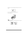
1. Using scissors, cut the leading edge of the paper roll as shown
below.
2. Turn on the printer and open the printer cover.
3. Insert the paper roll.
EP
SO
N
ED
FE
E
AS
LE
RE
ER
N
IO
AT
LID
T
IP VA ER
CE
W
RE T
PO
OU
R
RO
Note:
Be sure to note the correct direction that the paper comes off the
roll as shown below.
1–10 Setting Up the Printer
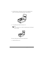
4. Hold both edges of the paper and insert it straight into the
paper slot. The printer feeds the paper automatically.
EP
SO
N
ED
FE
E
AS
LE
RE
ON
TI
DA
LI
T
IP VA ER
CE
W
RE UT
PO
O
R
RO
ER
5. Tear off the paper; then close the cover.
Note:
Before closing the cover, make sure that the paper from the paper
roll is not slack.
EP
SO
N
ED
FE
E
AS
LE
RE
N
IO
AT
LID
T
IP VA
R
CE
WE
RE T
PO
OU
R
RO
ER
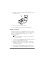
To remove the paper roll, follow the steps below.
1. Open the printer cover.
Setting Up the Printer 1–11
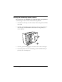
2. Pull up the paper and cut the paper at the dotted line shown in
the illustration below.
Cut here
EP
SO
N
ED
FE
SE
EA
REL
ON
TI
DA
LI
PT VA
EI
ER
W
RECUT
PO
O
R
RO
ER
3. Remove the paper roll from the printer.
4. Press the FEED button to remove the remaining paper.
Running the Self Test
Any time that you want to check the performance of your printer,
you can run the self test described below. This shows whether your
printer is working correctly. It is independent of any other
equipment or software.
Note:
Be sure to install the ribbon cassette and the paper roll before
you run the self test.
1. To perform the self test, hold down the FEED button while you
turn on the printer with the power switch.
2. The printer prints the current printer settings and then the
RECEIPT OUT light flashes to indicate that the printer is in the
test printing standby state.
3.
Press the FEED button to start the second part of the test, in
which the printer prints a pattern using the built-in character set.
1–12 Setting Up the Printer
4. After the printer completes a certain number of lines, it prints
the following:
*** completed ***
Then it enters the normal mode.
Note:
If you want to pause the self test manually, press the FEED
button. Press the FEED button again to continue the self test.
Setting the DIP Switches
Einstellen der DIP-Schalter
CAUTION / VORSICHT:
Turn off the printer while removing the DIP switch cover to
prevent an electrical short, which can damage the printer.
Den Drucker vor Abnahme der DIP-Schalterabdeckung
ausschalten, um einen Kurzschluß zu verhindern, durch den
der Drucker beschädigt werden könnte.
If you have special requirements, you can change the DIP switch
settings.
Wenn besondere Anforderungen vorliegen, können die DIPSchaltereinstellungen geändert werden.
1. Make sure that the printer is off.
Sicherstellen, daß der Drucker ausgeschaltet ist.
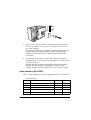
2. Turn the printer over and remove the DIP switch access cover,
as shown below.
Den Drucker umdrehen und die DIP-Schalterabdeckung
abnehmen (siehe Abbildung).
Setting Up the Printer 1–13
DSW1
DSW2
3. There are two sets of switches. Notice that ON is marked on
each set of switches. Use tweezers or another narrow tool to
move the switches.
Es gibt zwei Gruppen von Schaltern. Auf beiden Gruppen ist
die Einstellung ON (EIN) markiert. Zum Verschieben der
Schalter eine Pinzette oder ein anderes kleines Werkzeug
verwenden.
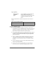
4. Use the following tables to set the DIP switches. Numbers
starting with 1 are in the first set, and numbers starting with 2
are in the second.
Die DIP-Schalter anhand der folgenden Tabellen einstellen.
Schalter, die mit 1 beginnen, befinden sich in der ersten
Gruppe, Schalter, die mit 2 beginnen, in der zweiten Gruppe.
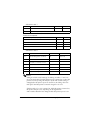
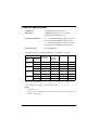
Serial Interface (TM-U325D)
These are the settings for printers equipped with a serial interface.
DIP Switch Set 1
Switch
Function
ON
OFF
1-1
Data reception error
Ignored
Prints”?”
1-2
Receive buffer capacity
45 bytes
4K bytes
1-3
Handshaking
XON/XOFF
DTR/DSR
1-4
Word length
7 bits
8 bits
1-5
Parity check
Yes
No
1–14 Setting Up the Printer
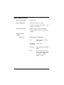
DIP Switch Set 1
Switch
Function
ON
OFF
1-6
Parity selection
Even
Odd
1-7, 1-8
Transmission speed (see table below)
Transmission Speed
Transmission Speed (BPS)-bits per second
1-7
1-8
2400
ON
ON
4800
OFF
ON
9600
ON
OFF
19200
OFF
OFF
DIP Switch Set 2
Switch
Function
ON
OFF
2-1
Handshaking (BUSY condition)
Receive buffer
full
Off line or receive
buffer full
2-2
Not defined
—
—
2-3
Select number of characters per
line (CPL) 7 × 9 font/9 × 9 font
42CPL/35CPL
40CPL/33CPL
2-4, 2-5
Not defined
—
—
2-6
Internal use
—
Fixed to Off
2-7
I/F pin 6 reset signal
Enabled
Disabled
2-8
I/F pin 25 reset signal
Enabled
Disabled
Notes:
Changes in DIP switch settings (excluding switches 2-7 and 2-8)
are recognized only when the printer power is turned on or when the
printer is reset by using the interface. If the DIP switch setting is
changed after the printer power is turned on, the change does not
take effect until the printer is turned on again or is reset.
If DIP switch 2-7 or 2-8 is turned on while the printer is turned on,
the printer may be reset, depending on the signal state.
DIP switches should not be changed while the printer power is on.
Setting Up the Printer 1–15
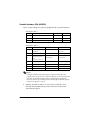
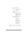
Parallel Interface (TM-U325PD)
These are the settings for printers equipped with a parallel interface.
DIP Switch Set 1
Switch
Function
ON
OFF
1-1
Auto line feed
Enabled
Disabled
1-2
Receive buffer capacity
45 bytes
4K bytes
1-3~1-8
Not defined
—
—
DIP Switch Set 2
Switch
Function
ON
OFF
2-1
Handshaking (BUSY
condition)
Receive buffer full
Off line or receive
buffer full
2-2
Not defined
—
—
2-3
Select number of
characters per line
(CPL)
7 × 9 font/9 × 9 font
42CPL/35CPL
40CPL/33CPL
2-4, 2-5
Not defined
—
—
2-6
Internal use
—
Fixed to Off
2-7
Not defined
—
—
2-8
I/F pin 31 reset signal
Fixed to On
—
Notes:
Changes in DIP switch settings are recognized only when the
printer power is turned on or when the printer is reset by using the
interface. If the DIP switch setting is changed after the printer
power is turned on, the change does not take effect until the printer
is turned on again or is reset.
5. Replace the DIP switch cover and secure it with the screw.
Die DIP-Schalterabdeckung wieder aufsetzen und mit der
Schraube befestigen.
1–16 Setting Up the Printer
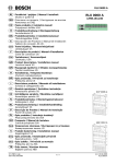
Using the Power Switch Cover
Verwendung der Netzschalterabdeckung
WARNING / WARNUNG:
If an accident occurs when the power switch cover is
attached, unplug the power supply cord from the outlet
immediately; otherwise the printer may be damaged.
Wenn ein Unfall auftritt und die Netzschalterabdeckung
aufgesetzt ist, das Netzkabel sofort aus der Steckdose
herausziehen. Andernfalls kann der Drucker beschädigt
werden.
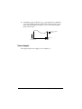
You can use the provided power switch cover to protect the power
switch from accidental or improper operation. Attach the cover as
shown in the illustration below.
You can turn the power on or off with the switch cover attached by
inserting a pointed object (like a ball point pen) through either of
the two small holes on the switch cover.
Mit der mitgelieferten Netzschalterabdeckung läßt sich der Netzschalter vor versehentlicher oder unbefugter Benutzung schützen.
Die Abdeckung ist wie in der Abbildung dargestellt anzubringen.
Um den Drucker ein- und auszuschalten, während die
Netzschalterabdeckung aufgesetzt ist, einen spitzen Gegenstand
(wie z.B. einen Kugelschreiber) in eine der beiden kleinen
Öffnungen in der Abdeckung einführen.
EPS
ON
FE
ED
RE
LE
AS
E
RE
OU
CE
T
IPT
ER
RO
VA
R
LID
ATION
PO
WE
R
Setting Up the Printer 1–17
Affixing the Fastening Tape (Option)
Two sets of tape are included as an option to fasten your printer to
a countertop or other surface. Follow the steps below:
1. Clean the countertop or other surface where the printer will be
installed.
2. Peel the green backing paper off of one side of each of the two
sets of tapes and affix them to the bottom of the printer, as
shown below.
3. Peel the green backing paper off of the other side of the tapes.
4. Press the printer onto the countertop; it will be held firmly in
place by the fastening tape.
1–18 Setting Up the Printer
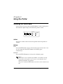
Chapter 2
Using the Printer
Operating the Control Panel
You can feed or release paper with the buttons on the control panel.
The indicator lights help you monitor the printer’s status.
FEED
RELEASE
RECEIPT
VALIDATION
OUT
ERROR
POWER
Switch
The power switch on the front of the printer turns the printer on
and off.
Buttons
FEED
Press the FEED button once to advance the paper roll one line. You
can also hold down the FEED button to feed the paper
continuously.
RELEASE
Press the RELEASE button to release the validation paper.
Notes:
These buttons can be disabled by the ESC c 5 command, but they
work whenever the printer cover is open, even if they have been
disabled by the ESC c 5 command.
The power switch and FEED button can also be used to start the self
test.
Using the Printer 2-1
Indicator lights
The control panel lights provide information on printer conditions.
POWER (Green)
The POWER light is on when the printer power is on.
RECEIPT OUT (Red)
This light is on when the paper roll is at the end or near the end.
This light flashes in the following cases. When it flashes, press the
FEED button.
❏ In the self-test standby state
VALIDATION (Green)
The light is on when validation paper is inserted and the printer is
ready to print. The light flashes when the printer is in the
validation insertion/removal waiting state.
ERROR (Red)
This light is on when the printer is off line (except during paper
feed using the FEED button and during the self-test). It flashes to
indicate an error condition.
The flashing pattern shown below indicates that the temperature of
the print head is too high. The printer recovers automatically and
resumes printing when the head cools.
Approximately 160 ms
2-2 Using the Printer
If the printer stops working and the ERROR light is flashing, turn
the printer off, check for jammed paper, and remove the paper by
following the instructions on page 3-3, if necessary. Then turn the
printer back on. If the printer still does not work, unplug the power
supply cord from the outlet immediately, and contact a qualified
service person.
CAUTION / VORSICHT:
The print head becomes very hot during printing. Allow it to
cool before you reach into the printer.
Der Druckkopf wird beim Drucken sehr heiß. Warten, bis er
sich abgekühlt hat, bevor Sie in den Drucker fassen.
Do not use aerosol sprayers containing flammable gas inside
or around this product. Doing so may cause fire.
Verwenden Sie keine brennbaren Sprühmittel in und in der
Nähe des Gerätes. Brandgefahr!
Using the Printer 2-3
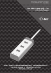
Validation Paper Handling
Notes:
Use only validation paper that matches the printer’s specifications.
See Paper Specifications in Chapter 4.
Be sure that a paper roll is loaded before you use validation paper.
Be sure that the validation paper is flat, without curls, folds, or
wrinkles.
1. Send appropriate control commands from the computer to
print on validation paper.
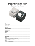
2. When the VALIDATION light flashes, insert the validation
paper into the validation paper inlet using the right edge of the
validation paper inlet as a guide. (Follow steps ➀ and ➁ in the
illustration.)
POW
ER
ERR
OR
FEE
D
N
SO
EP
VAL
IDAT
ION
2
REL
EAS REC
E
OUT EIPT
1
3. Make sure you insert the validation paper into the inlet as far as
it will go.
4. When the validation paper is detected by the sensor, the
VALIDATION light is changed from flashing to on and the
paper is automatically drawn into the printer and printing
begins.
5. When the VALIDATION light begins flashing after printing,
remove the validation.
2-4 Using the Printer
Chapter 3
Troubleshooting
Troubleshooting
This chapter gives solutions to some of the more common printer
problems.
General Problems
The lights on the control panel do not come on.
Make sure that the power supply cords are correctly plugged into
the printer, the power unit, and to the power outlet.
Make sure that power is supplied to the power outlet. If the outlet
is controlled by a switch or timer, use another outlet.
Printing Problems
The ERROR light is flashing and the printer does not print.
First, turn off the printer and check for a paper jam. (See the paper
jam description on page 3-3.)
If there is no paper jam and the printer has been printing for quite a
while, the print head may be overheated. If the print head is
overheated, the printer will resume printing when the head has
cooled (usually about 30 seconds).
If there is no paper jam and the print head is not overheated, turn
off the printer and turn it back on after about 10 seconds. If the
printer still does not work, unplug the power supply cord from the
outlet immediately. Then contact a qualified service person.
Troubleshooting 3-1
The ERROR light is off, but nothing is printed.
Try to run the self test to check that the printer works properly. See
the self test instructions in Chapter 1 to run the self test. If the self
test does not work, contact your dealer or a qualified service
person.
If the self test works properly, check the following:
1. Check the connection at both ends of the interface cable
between the printer and the computer. Also make sure that this
cable meets the specifications for both the printer and the
computer.
2. The data transmission settings may be different between the
printer and computer. Make sure that the printer’s DIP switch
settings for data transmission are the same as the computer’s.
You can print the printer’s interface settings using the self test.
If the printer still does not print, contact your dealer or a qualified
service person.
The printer sounds like it is printing, but nothing is printed.
The ribbon cassette may not be installed properly. See the
instructions in Chapter 1.
The ribbon may be worn out. Replace the ribbon cassette as
described in Chapter 1.
The printout is faint.
The ribbon may be worn out. Replace the ribbon cassette as
described in Chapter 1.
3-2 Troubleshooting
A line of dots is missing in the printout.
The print head may be damaged. Stop printing and contact your
dealer or a qualified service person.
Removing Jammed Paper
Follow these steps to clear a paper jam:
CAUTION / VORSICHT:
The print head becomes very hot during printing. Allow it to
cool before you reach into the printer.
Der Druckkopf wird beim Drucken sehr heiß. Warten, bis er
sich abgekühlt hat, bevor Sie in den Drucker fassen.
1. Open the printer cover.
2. Pull up the paper and cut the paper at the dotted line shown in
the illustration below.
Cut here
EP
SO
N
ED
FE
E
AS
LE
RE
N
IO
DAT
LI
T
IP VA ER
CE
W
RE UT
PO
O
R
RO
ER
3. Remove the paper roll from the printer.
4. Remove the ribbon cassette.
Troubleshooting 3-3
5. Loosen the screw on the print head cover as shown below.
EP
SO
N
ED
FE
E
AS
LE
RE
ON
TI
DA
LI
T
IP VA ER
CE
W
RE UT
PO
O
R
RO
ER
6. Lift up the print head cover.
EP
SO
N
ED
FE
SE
EA
REL
ER
ON
TI
DA
LI
PT VA
EI
ER
W
RECUT
PO
O
R
RO
7. Remove all the jammed paper.
Note:
Do not pull the jammed paper in the opposite direction of paper
feeding.
8. Replace the print head cover and secure it with the screw.
9. Replace the ribbon cassette and paper roll; then close the
printer cover.
3-4 Troubleshooting
Hexadecimal Dump
This feature allows experienced users to see exactly what data is
coming to the printer. This can be useful in finding software
problems. When you turn on the hex dump function, the printer
prints all commands and other data in hexadecimal format along
with a guide section to help you find specific commands.
To use the hexadecimal dump feature, follow these steps:
1. Turn on the printer while you hold down the FEED button; then
close the cover.
2. When the printer enters the hexadecimal dump mode, it prints
“Hexadecimal Dump.”
3. Run any software program that sends data to the printer. The
printer prints all the codes it receives in a two-column format.
The first column contains the hexadecimal codes and the
second column gives the ASCII characters that correspond to
the codes.
Hexadecimal Dump
1B 40 1B 21 30 41 42 43 . @ . ! 0 A B C
44 45 46 47 0A
DE F G.
❏ A period (.) is printed for each code that has no ASCII
equivalent.
❏ During the hexadecimal dump, all commands except DLE
EOT and DLE ENQ are disabled.
4. When the printing finishes, turn off the printer or reset it to
turn off the hexadecimal dump mode.
Note:
Insufficient print data to fill the last line can be printed by setting
the printer off-line.
Troubleshooting 3-5
3-6 Troubleshooting
Chapter 4
Reference Information
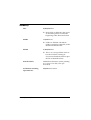
Printing Specifications
Printing Method:
Serial impact dot-matrix
Head wire
configuration:
9-pin serial configuration
Printing Direction:
Bi-directional, logic-seeking
Characters/line
(default):
See table on page 4-2.
Character spacing
(default)
Fonts A and B:
See table on page 4-2.
Printing speed:
Approx. 3.5 lines/second (40 columns,
16 cpi)
Approx. 6.4 lines/second (16 columns,
16 cpi)
(excluding data transmission time and
processing time)
[cpi: characters per 25.4 mm (characters per inch)]
Note:
When printing exceeds the allowable print duty cycle, the printer automatically
stops printing. In this case, the printing speed described above is not
guaranteed.
Reference Information 4-1
Character Specifications
Number of
characters
Alphanumeric characters: 95
Extended graphics: 128 × 8 pages,
International characters: 32
Character structure:
7 × 9 (the total number of dots for each
horizontal line: 400 in half dot units)
9 × 9 (the total number of dots for each
horizontal line: 400 in half dot units)
Character size:
See table below.
Character Sizes, Character Spacing, Character Columns
Character structure
WxH
(mm)
Character size
W x H (mm)
Character
spacing
Dot space
CPL
CPI
ANK
1.2 x 3.1
3 half dots
40
16
Graphics
1.7 x 3.1
0
40
16
ANK
1.6 x 3.1
3 half dots
33
13.3
Graphics
2.0 x 3.1
0
33
13.3
ANK
1.2 x 3.1
2 half dots
42
17.8
Character
7x9
9x9
7x9
Graphics
1.6 x 3.1
0
42
17.8
ANK
1.6 x 3.1
2 half dots
35
14.5
Graphics
1.9 x 3.1
0
35
14.5
9x9
[cpl: characters per line]
[cpi: characters per 25.4 mm (characters per inch)]
Notes:
• The default is 7 x 9.
• 2-dot spacing in half dot units and 3-dot spacing in half dot units depend on
the DIP switch setting.
4-2 Reference Information
Paper Specifications
Paper feed method:
Friction feed
Paper feed pitch:
Default 4.23 mm {1/6 inch}
Can be set in units of 0.176 mm {1/144
inch} by commands.
Paper feed speed:
Approx. 105.918 mm {4.17 inches}/
second (25 lines/second) (continuous
feeding)
Paper size and
weight:
Paper roll:
Normal paper (single-ply)
Size:
Width 76 mm ± 0.5 mm
{3.0" ± 0.02"}
Maximum 83 mm {3.27"}
outside dia:
Thickness:
0.06 to 0.085 mm {.0024 to
.0033"}
Mass:
52.3 to 64.0 g/m2 {13.9 to
17 lbs} (45 to 55 Kg {20.41
to 24.94 lbs}/1000 sheets/
1091 mm × 788 mm
{43.00" × 31.02"}
Reference Information 4-3
Pressure sensitive paper
Maximum 1 original + 2 copies
Size:
Width 76 mm ± 0.5 mm
{3.0" ± 0.02"}
Maximum 83 mm {3.27"}
outside dia:
Thickness:
0.05 to 0.08 mm {.0020 to
.0031"}
(Total thickness should
be 0.2 mm or less and
each sheet should be 0.05
to 0.08 mm.)
Recommend MITSUBISHI PAPER
-ed paper: MILLS, LTD.
Non-carbon paper
(blue color)
Top and middle sheets:
N40Hi
(thickness: 0.06 mm,
mass: 47.2 g/m2 )
Bottom sheet: N60
(thickness: 0.08 mm,
mass: 68.0 g/m2)
Note:
When using original + 2 copies ( the total is 3), the edges of the
paper might fold when the temperature is 34°C and the humidity is
90%.
4-4 Reference Information
Validation paper:
Normal, pressure sensitive, and
carbon copy paper
Paper size
(W × L):
135 mm × 70 mm (minimum) to
182 mm × 182 mm (maximum)
{5.31” × 2.76” to 7.17” × 7.17”}
(maximum 9 lines at 4.23 mm {.17”}
pitch)
Single-ply
paper thickness
(without copy
paper):
0.09 mm to 0.12 mm {.0035” to .0047”}
Copy paper
thickness:
Backing
paper:
0.07 mm to 0.12 mm
{.0028” to .0047”}
Copy and
original
paper:
0.04 mm to 0.07 mm
{.0016” to .0028”}
Carbon
Approximately 0.035 mm
copy paper: {.00138”}
Total
thickness:
Example:
0.09 mm to 0.31 mm
{.0035” to .012”}
Original + 2-ply copy
Original paper: 0.04 mm {.0016”}
Carbon copy paper: 0.07 mm {.0028”}
(0.035 mm {.0138”} × 2 sheets)
Copy paper: 0.04 mm {.0016”}
Backing paper: 0.07 mm {.0028”}
Roll paper: 0.08 mm {.0031”}
Total thickness: 0.30 mm {.0118”}
Reference Information 4-5
Copy capability
Paper roll and
validation
paper:
Copy capability is greatly influenced
by the ambient temperature, so
printing must be performed under the
conditions described in the table
below.
Relationship between ambient temperature and number of
copies
Paper roll and validation paper:
Number of copies
Ambient temperature
Original + 2 copies
10° to 40°C {50° to 104°F}
Original + 1 copy
5° to 50°C {41° to 122°F}
Notes on validation paper
❏ For correct validation printing, be sure that a paper roll is
loaded before you use validation paper. Also be aware that the
printing on validation paper may also be visible on the roll
paper if the roll paper is pressure-sensitive paper.
❏ Use validation paper that is flat, without curls, folds, warps, or
wrinkles, especially at the paper edge. Otherwise, the paper
may become ink stained or the ribbon may get caught in the
printer mechanism.
❏ Choose validation paper carefully when glue is on the edge,
since paper feeding and insertion are affected by gluing
conditions (e.g., glue quality, method, and length) and glue
location.
❏ Using a multi-ply copy paper with a thick middle sheet may
decrease copying capability.
❏ Printing noise may change depending on paper thickness.
Noise may increase when thick single-ply paper is used.
4-6 Reference Information
❏ Validation paper with holes (e.g., sprocket holes) within the
areas shown below must not be used. Otherwise, the paper
cannot be detected by the paper sensor. Translucent paper
must not be used.
: Holes are prohibited
in this area.
7mm (.28”)
Inserting direction
11mm (.43”)
Power Supply
The supported power supply is AC Adapter, C.
Reference Information 4-7
Reliability
Life:
20,000,000 lines
❏ End of Life is defined as the point
at which the printer reaches the
beginning of the Wearout Period.
MTBF:
180,000 hours
❏ Failure is defined as Random
Failure occurring at the time of the
Random Failure Period.
MCBF:
49,000,000 lines
❏ This is an average failure interval
based on failures relating to
wearout and random failures up to
the life of 20 million lines.
Print head life:
150 million characters (when printing
an average of 2 dots/wire per
character)
Validation switching
operation life:
500,000 transactions
4-8 Reference Information
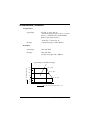
Environmental Conditions
Temperature
Operating
0 to 50 ° C {32 to 122 ° F}
(when the temperature is 30 ° C or more,
there is a limitation for the humidity.
Refer to the figure below.)
–10 to 50 ° C {14 to 122° F}
(except for paper, and a ribbon)
Storage
Humidity
Operating
10 to 90% RH
Storage
10 to 90% RH
(except for paper and a ribbon)
Operating environment range
34 ° C, 90%
Relative humidity
90
80
40 ° C, 65%
60
40
50 ° C, 35%
20
10
0
0
10
20
50
40
30
Environment temperature [ ° C]
Reference Information 4-9
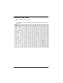
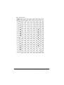
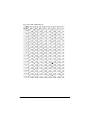
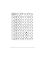
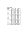
Character Code Tables
SP in a table represents space.
Page 0 (PC437: U.S.A., Standard Europe) (International character
set: U.S.A)
FS
4-10 Reference Information
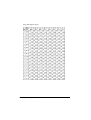
Page 1 (Katakana)
Reference Information 4-11
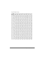
Page 2 (PC850: Multilingual)
4-12 Reference Information
Page 3 (PC860: Portuguese)
Reference Information 4-13
Page 4 (PC863: Canadian-French)
4-14 Reference Information
Page 5 (PC865: Nordic)
Reference Information 4-15
Page 254 (Space Page)
4-16 Reference Information
Page 255 (Space Page)
Reference Information 4-17
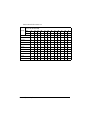
International character set
ASCII code (hexadecimal)
Country
Hex
23
24
40
5B
5C
5D
5E
60
7B
7C
7D
7E
Dec
35
36
64
91
92
93
94
96
123
124
125
126
U.S.A.
#
$
@
[
\
]
^
`
{
¦
}
~
France
#
$
à
°
ç
§
^
`
é
ù
è
¨
Germany
#
$
§
Ä
Ö
Ü
^
`
ä
ö
ü
ß
\
]
^
`
{
¦
}
~
Æ
Ø
Å
^
`
æ
ø
å
~
É
Ä
Ö
Å
Ü
é
ä
ö
å
ü
@
°
\
é
^
ù
à
ò
è
ì
U.K.
£
$
@
[
Denmark I
#
$
@
Sweden
#
¤
Italy
#
$
Spain
Pt
$
@
¡
Ñ
¿
^
`
¨
ñ
}
~
Japan
#
$
@
[
¥
]
^
`
{
¦
}
~
Norway
#
¤
É
Æ
Ø
Å
Ü
é
æ
ø
å
ü
Denmark II
#
$
É
Æ
Ø
Å
Ü
é
æ
ø
å
ü
4-18 Reference Information
WEEE (Waste Electrical and Electronic Equipment) Directive
This information only applies to customers in the European Union, according to
Directive 2002/96/EC OF THE EUROPEAN PARLIAMENT AND OF THE COUNCIL
OF 27 January 2003 on waste electrical and electronic equipment (WEEE) and
legislation transposing and implementing it into the various national legal systems.
For other countries, please contact your local government to investigate the
possibility of recycling your product.
English
The crossed out wheeled bin label that can be found on
your product indicates that this product should not be
disposed of via the normal household waste stream. To
prevent possible harm to the environment or human
health please separate this product from other waste
streams to ensure that it can be recycled in an
environmentally sound manner. For more details on
available collection facilities please contact your local
government office or the retailer where you purchased
this product.
Deutsch
Der Aufkleber mit durchgekreuzter Mülltonne an
diesem Produkt weist darauf hin, dass dieses Produkt
nicht im normalen Hausmüll entsorgt werden darf. Zur
Vermeidung einer möglichen Beeinträchtigung der
Umwelt oder der menschlichen Gesundheit und um zu
gewährleisten, dass es in einer umweltverträglichen
Weise recycelt wird, darf dieses Produkt nicht in den
Hausmüll gegeben werden. Informationen zu
Entsorgungseinrichtungen erhalten Sie bei der
zuständigen Behörde oder dem Geschäft, in dem Sie
dieses Produkt erworben haben.
Français
Português
A etiqueta com o símbolo de um contentor de lixo
traçado com uma cruz que aparece no produto indica
que este produto não deve ser deitado fora juntamente
com o lixo doméstico. Para evitar possíveis danos no
ambiente ou na saúde pública, por favor separe este
produto de outros lixos; desta forma, terá a certeza de
que pode ser reciclado através de métodos não
prejudiciais ao ambiente. Para obter mais informações
sobre os locais de recolha de lixo disponíveis, contacte
a sua junta de freguesia, câmara municipal ou
localonde comprou este produto.
Nederlands
Op uw product is een label van een rolcontainer met
een kruis erdoor aangebracht. Dit label wil zeggen dat
dit product niet bij het normale huishoudelijk afval mag
worden ingezameld. Om eventuele schade aan het
milieu of de gezondheid van de mens te voorkomen
moet dit product gescheiden van al het ander afval
worden ingezameld, zodat het op een verantwoorde
wijze kan worden verwerkt. Voor meer informatie over
uw lokale afvalinzameling wendt u zich tot uw
gemeente of de leverancier bij wie u dit product hebt
gekocht.
L'étiquette apposée sur ce produit et représentant une
poubelle barrée indique que le produit ne peut être mis au
rebut avec les déchets domestiques normaux. Afin
d'éviter d'éventuels dommages au niveau de
l'environnement ou sur la santé, veuillez séparer ce
produit des autres déchets de manière à garantir qu'il soit
recyclé de manière sûre au niveau environnemental.
Pour plus de détails sur les sites de collecte existants,
veuillez contacter l'administration locale ou le détaillant
auprès duquel vous avez acheté ce produit.
Dansk
Italiano
Suomi
L'etichetta con il contenitore barrato applicata
sull'imballo indica che il prodotto non deve essere
smaltito tramite la procedura normale di smaltimento
dei rifiuti domestici. Per evitare eventuali danni
all'ambiente e alla salute umana, separare questo
prodotto da altri rifiuti domestici in modo che possa
essere riciclato in base alle procedure di rispetto
dell'ambiente. Per maggiori dettagli sulle strutture di
raccolta disponibili, contattare l'ufficio competente del
proprio comune o il rivenditore del prodotto.
Español
La etiqueta de un contenedor tachado que hallará en
su producto indica que este producto no se puede tirar
con la basura doméstica normal. Para impedir posibles
daños medioambientales o para la salud, separe este
producto de otros canales de desecho para garantizar
que se recicle de una forma segura para el medio
ambiente. Para más información sobre las
instalaciones de recolección disponibles, diríjase a las
autoridades locales o al punto de venta donde adquirió
este producto.
Etiketten med et kryds over skraldespanden på hjul,
der sidder på produktet, angiver, at dette produkt ikke
må bortskaffes sammen med almindeligt
husholdningsaffald. For at beskytte miljø og helbred
skal dette produkt bortskaffes separat, så det kan
genbruges på en måde, der er god for miljøet. Kontakt
de lokale myndigheder eller den forhandler, hos hvem
du har købt produktet, vedrørende steder, hvor du kan
aflevere produktet.
Laite on merkitty jäteastia-symbolilla, jonka yli on
vedetty rasti. Tämä tarkoittaa, ettei laitetta saa hävittää
normaalin talousjätteen mukana. Älä hävitä laitetta
normaalin jätteen seassa vaan varmista, että laite
kierrätetään ympäristöystävällisellä tavalla, jottei
ympäristölle tai ihmisille aiheudu vahinkoa. Lisätietoja
kierrätyksestä ja keräyspisteistä saa ottamalla yhteyttä
paikallisiin viranomaisiin tai jälleenmyyjään, jolta laite
ostettiin.
Svenska
Symbolen med en överkorsad soptunna innebär att
denna produkt inte får kastas i vanligt hushållsavfall.
För att skydda miljön ska denna produkt inte kastas
tillsammans med vanligt hushållsavfall utan lämnas för
återvinning på tillbörligt sätt. För mer information om
uppsamlingsplatser kontakta din lokala myndighet eller
den återförsäljare där du har köpt produkten.
Norsk
Det er krysset over merket av beholderen på hjul som
vises på produktet, som angir at dette produktet ikke
skal kastes sammen med vanlig husholdningsavfall.
Hold dette produktet atskilt fra annet avfall slik at det
kan resirkuleres på en miljømessig forsvarlig måte og
dermed forhindre eventuell skade på miljø eller helse.
Hvis du vil ha mer informasjon om hvor produktet kan
leveres inn, kontakter du kommunale myndigheter eller
forhandleren der du kjøpte dette produktet.
Česky
Štítek s přeškrtnutým odpadkovým košem na
kolečkách, který lze nalézt na výrobku, označuje, že
tento product se nemá likvidovat s běžným domovním
odpadem. V zájmu ochrany životního prostředí a
lidského zdraví zlikvidujte tento výrobek jako tříděný
odpad, který se recykluje způsobem šetrným k
životnímu prostředí. Podrobnější informace o sběrných
dvorech pro tříděný odpad získáte na obecním úřadě
nebo u prodejce, u kterého jste příslušný výrobek
zakoupili.
Magyar
A terméken található, áthúzott szemetest ábrázoló
címke azt jelzi, hogy ezt a terméket nem szabad a
rendes háztartási szeméttel együtt kidobni. Az
esetleges környezeti- vagy egészségkárosodást
megelõzendõ, kérjük, hogy ezt a terméket a többi
szeméttõl elkülönítve helyezze el, és biztosítsa, hogy
azt környezetbarát módon újrahasznosítsák. A
rendelkezésére álló begyûjtõ létesítményekrõl kérjük
tájékozódjon a megfelelõ helyi állami szerveknél vagy
a viszonteladónál, ahol a terméket vásárolta.
Polski
Symbol przekreślonego kosza znajdujący się na
produkcie oznacza, że nie może on być utylizowany
razem z normalnymi odpadami z gospodarstwa
domowego. Aby zapobiec potencjalnemu zagrożeniu
dla środowiska lub zdrowia ludzkiego, produkt ten
należy odseparować od reszty odpadów z
gospodarstwa domowego i utylizować w ekologicznie
właściwy sposób. Szczegółowe informacje na temat
punktów zbiórki odpadów można uzyskać w lokalnych
urzędach lub u sprzedawcy danego produktu.
Slovensky
Štítok s preškrtnutým odpadkovým košom na
kolieskach, ktorý je možné nájst’ na výrobku, označuje,
že tento product sa nemá likvidovat’ s bežným
komunálnym odpadom. V záujme ochrany životného
prostredia a ľudského zdravia zlikvidujte tento výrobok
ako triedený odpad, ktorý sa recykluje spôsobom
šetrným k životnému prostrediu. Podrobnejšie
informácie o zberných dvoroch pre triedený odpad
získate na obecnom úrade alebo u predajcu, u ktorého
ste príslušný výrobok zakúpili.
Slovenski
Prečrtan koš za smeti na etiketi, katero lahko najdete
na vašem izdelku, pomeni, da tega izdelka ne smete
odvreči podobno kot vse ostale smeti. Da bi preprečili
morebitne škodljive vplive na okolje ali zdravje, ločite
izdelek od vseh ostalih in poskrbite, da bo recikliran na
okolju prijazen način. Natančne informacije o tem, kje
se nahajajo primerna odlagališča, pridobite v vašem
krajevnem uradu ali pri prodajalcu.
Eesti
Teie tootele kleebitud tähis, mis kujutab ratastega
prügikonteinerit, millele on rist peale tõmmatud, keelab
toote kõrvaldamise majapidamisjäätmetega sarnasel
viisil. Keskkonnale või inimeste tervisele tekitatava
võimaliku kahju vältimiseks eraldage toode teistest
jäätmetest, et tagada selle korduvkasutamine
keskkonnasäästlikul viisil. Kui soovite saada rohkem
teavet võimalike kogumispunktide kohta, võtke
ühendust kohaliku omavalituse ametnikuga või teile
toote müünud jaemüüjaga.
Lietuviðkai
Uþbraukta ratuota ðiukðliadëþës etiketë, kurià rasite ant jûsø
produkto, reiðkia, kad ðis produktas neturëtø bûti iðmestas
kartu su áprastinëmis buitinëmis ðiukðlëmis. Siekiant
iðvengti galiamos þalos aplinkai bei þmoniø sveikatai,
praðome atskirti ðá produktà nuo kitø atliekø, ir ásitikinti,
kad jis bûtø perdirbtas aplinkai nepavojingu bûdu. Jei reikia
iðsamesnës informacijos apie atliekø surinkimo ypatumus,
praðome kreiptis á savo vietos valdþios ástaigas arba á
maþmeniná pardavëjà, ið kurio jûs ásigijote ðá produktà.
Latviski
Maríçjums ar pârsvîtrotu atkritumu tvertni uz ritenîðiem, kas
redzams uz izstrâdâjuma, norâda, ka ðo izstrâdâjumu
nedrîkst likvidçt kopâ ar parastajiem sadzîves atkritumiem.
Lai novçrstu iespçjamo kaitçjumu videi vai cilvçku
veselîbai, lûdzu, atdaliet ðo izstrâdâjumu no citiem
atkritumiem, tâdçjâdi nodroðinot tâ otrreizçjo pârstrâdi videi
droðâ veidâ. Papildinformâcijai par pieejamajâm atkritumu
savâkðanas iespçjâm, lûdzu, sazinieties ar vietçjo paðvaldîbu
vai mazumtirgotâju, no kura jûs iegâdâjâties ðo
izstrâdâjumu.
Ελληνικά
Η διαγραµµένη ετικέτα του τροχοφόρου κάδου
απορριµµάτων που θα βρείτε πάνω στο προϊόν σας
υποδεικνύει ότι αυτό το προϊόν δεν πρέπει να
απορρίπτεται µέσω του κανονικού δικτύου αποκοµιδής
οικιακών απορριµµάτων. Για να αποτρέψετε πιθανές
επιπτώσεις στο περιβάλλον ή την ατοµική υγεία,
παρακαλούµε να διαχωρίσετε αυτό το προϊόν από
άλλα δίκτυα αποκοµιδής ώστε να διασφαλίσετε ότι είναι
δυνατή η ανακύκλωσή του µε έναν περιβαλλοντικά
θεµιτό τρόπο. Για περισσότερες πληροφορίες σχετικά
µε τις διαθέσιµες δυνατότητες συλλογής
απορριµµάτων, παρακαλούµε να επικοινωνήσετε µε
την τοπική κυβερνητική αρχή ή το κατάστηµα λιανικής
από όπου αγοράσατε αυτό το προϊόν.
Türkçe
Ürününüzün üzerinde bulunan çarpı işaretli tekerlekli
kutu etiketi, bu ürünün normal ev atık sistemi
vasıtasıyla elden çıkarılmaması gerektiğini gösterir.
Çevreye ve insan sağlığına zarar vermeyi önlemek için,
lütfen bu ürünü çevreye zarar vermeyecek şekilde geri
dönüşüme tabi tutulmak üzere diğer atıklardan ayırın.
Mevcut toplama tesisleri ile ilgili ayrıntılı bilgi edinmek
için, yerel devlet makamlarıyla veya bu ürünü satın
aldığınız satıcıyla irtibata geçin.
Printed in China
1996.12