1
TM-T88II Series
User’s Manual
400852003
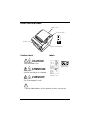
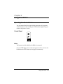
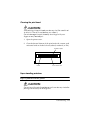
Printer Parts and Labels
Printer cover
Control panel
POWER
P
OW
ER
ER
RO
R
P
OU APE
R
FE T
ED
ERROR
PAPER
OUT
FEED
FEED
Cutter cover
Cover open button
Caution Labels
Labels
CAUTION:
Thermal head is hot.
Label inside
cutter section
ATTENTION:
La téte thermique est chaude.
Label inside
printer cover
VORSICHT:
Der Thermalkopf ist heiß.
Caution label above for the drawer kick-out connector.
Quick Reference
This Quick Reference will direct you to key areas of this Operator’s
Manual. For a complete listing of topics, see the Contents.
Printer Parts and Labels
Ordering Paper
inside front cover
page ix
Where to order paper.
Setting Up the Printer
page 1-1
How to set up the printer.
Installing and Replacing Paper
page 1-7
How to load or change the paper roll.
Solving Problems
page 3-1
How to correct problems.
i
All rights reserved. No part of this publication may be reproduced, stored in a
retrieval system, or transmitted in any form or by any means, electronic, mechanical,
photocopying, recording, or otherwise, without the prior written permission of Seiko
Epson Corporation. No patent liability is assumed with respect to the use of the
information contained herein. While every precaution has been taken in the
preparation of this book, Seiko Epson Corporation assumes no responsibility for
errors or omissions. Neither is any liability assumed for damages resulting from the
use of the information contained herein.
Neither Seiko Epson Corporation nor its affiliates shall be liable to the purchaser of
this product or third parties for damages, losses, costs, or expenses incurred by
purchaser or third parties as a result of: accident, misuse, or abuse of this product or
unauthorized modifications, repairs, or alterations to this product, or (excluding the
U.S.) failure to strictly comply with Seiko Epson Corporation’s operating and
maintenance instructions.
Seiko Epson Corporation shall not be liable against any damages or problems arising
from the use of any options or any consumable products other than those designated
as Original Epson Products or Epson Approved Products by Seiko Epson
Corporation.
EPSON and ESC/POS are registered trademarks of Seiko Epson Corporation.
NOTICE: The contents of this manual are subject to change without notice.
Copyright © 1998 by Seiko Epson Corporation, Nagano, Japan.
ii
EMC and Safety Standards Applied
Product Name: TM-T88II
Model Name: M129B
The following standards are applied only to the printers that are so
labeled. (EMC is tested using the EPSON PS-170 power supply)
Europe:
CE Marking
Safety: EN60950
North America:
EMI: FCC/ICES-003 Class A
Safety: UL 1950/CSA C22.2 No. 950
Japan:
EMI:
Oceania:
EMC: AS/NZS 3548
Taiwan:
EMI:
VCCI Class A
Class B
WARNING
The connection of a non-shielded printer interface cable to this printer will invalidate
the EMC standards of this device.
You are cautioned that changes or modifications not expressly approved by SEIKO
EPSON Corporation could void your authority to operate the equipment.
iii
CE Marking
The printer conforms to the following Directives and Norms
Directive 89/336/EEC
EN 55022 Class B
EN 55024
IEC 61000-4-2
IEC 61000-4-3
IEC 61000-4-4
IEC 61000-4-5
IEC 61000-4-6
IEC 61000-4-11
Directive 90/384/EEC
EN45501
FCC Compliance Statement
For American Users
This equipment has been tested and found to comply with the limits for a Class A
digital device, pursuant to Part 15 of the FCC Rules. These limits are designed to
provide reasonable protection against harmful interference when the equipment is
operated in a commercial environment.
This equipment generates, uses, and can radiate radio frequency energy and, if not
installed and used in accordance with the instruction manual, may cause harmful
interference to radio communications. Operation of this equipment in a residential
area is likely to cause harmful interference, in which case the user will be required to
correct the interference at his own expense.
FOR CANADIAN USERS
This Class A digital apparatus complies with Canadian ICES-003.
Cet appareil numérique de la classe A est conforme à la norme NMB-003 du Canada.
iv
GEREÄUSCHPEGEL
Gemäß der Dritten Verordnung zum Gerätesicherheitsgesetz
(Maschinenlärminformations- Verordnung-3. GSGV) ist der arbeitsplatzbezogene
Geräusch-Emissionswert kleiner als 70 dB(A) (basierend auf ISO 7779).
v
About This Manual
Setting Up and Using
❏
Chapter 1 contains information on unpacking the printer and setting it up.
❏
Chapter 2 contains information on using the printer.
❏
Chapter 3 contains troubleshooting information.
Reference
❏
Chapter 4 contains specifications.
❏
Appendix A tells how to change the DIP switch and paper near end settings.
Warnings, Cautions, and Notes
WARNING:
Follow warnings carefully to avoid serious bodily injury.
CAUTION:
Observe cautions to avoid minor injury to yourself or damage
to your equipment.
Note:
Notes have important information and useful tips on the operation of your
printer.
vi Quick Reference
Introduction
Features
TM-T88II Series printers are high-quality POS printers that can print on a paper roll.
The printers have the following features:
Printing
❏
High-speed printing: 28.4 lines/second (4.23mm (1/6”) feed) maximum.
❏
Low-noise thermal printing.
❏
High reliability due to a stable mechanism.
Application Software
❏
Command protocol is based on the ESC/POS® standard.
❏
Various layouts are possible by using page mode.
❏
Characters can be scaled up to 64 times as large as the standard size. Smoothing
is also possible.
❏
Bar code printing is possible by using a bar code command. Bar codes can be
printed both in the vertical direction (fence bar code) and in the horizontal
direction (ladder bar code).
❏
Repeated operations and copy printing are possible by using macro definitions.
❏
Character font size (12 x 24 font or 9 x 17 font) can be selected using a command.
Printer Handling
❏
Easy paper roll loading.
❏
An autocutter is standard.
❏
The printer allows easy maintenance for tasks such as head cleaning.
❏
Three different print densities can be selected by DIP switches.
❏
The built-in interface provides control capability for two drawers.
Introduction vii
Options and Accessories
❏
EPSON power supply unit, PS-170.
❏
Affixing tapes (model: DF-10).
❏
RS-485 interface board can be installed as a dealer option.
❏
Wall hanging bracket set (WH-10).
viii Introduction
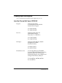
Ordering Paper and Supplies
You can order thermal roll paper from the supplier in your area.
Specified Thermal Roll Paper: NTP080-80
In Japan:
Nakagawa Seisakujo
2-5-21 Nishiki-Cho Warabi-Shi
Saitama-Ken 335 Japan
Tel: (048) 444-8211
Fax: (048) 443-6652
In U.S.A.:
Nakagawa Mfg (USA) Inc.
2305 Lincoln Avenue
Hayward, CA 94545 USA
Tel: (510) 782-0197
Fax: (510) 782-7124
In Europe:
Nakagawa Mfg (Europe) GmbH.
Krützpoort 16, 47804
Krefeld, Germany
Tel: 02151-711051
Fax: 02151-713293
In Southeast Asia:
N.A.K. Mfg (Malaysia) SDN BHD
Lot 19-11, Bersatu Industrial Complexs,
Jalan Satu, Kaw Per. Cheras Jaya,.
Balakong Industrial Area, 43200 Cheras.
Selangor Darul Ehsan, Malaysia
Tel: 03-9047896, 9047900, 9047691
Fax: 03-9047889
Introduction ix
Other Qualified Suppliers for Thermal Paper
The following suppliers sell thermal paper that may be used if
desired. Contact each company for information.
Original paper:
TF50KS-E
Nippon Paper Industry Co., Ltd.
1-12-1, Yuraku-Cho, Chiyoda-Ku
Tokyo 100 Japan
Tel: 03-3218-8000
Fax: 03-3216-1375
Original paper:
PD 160R
New Oji Paper Mfg. Co., Ltd.
7-5 Ginza 4-Chome Chuo-Ku
Tokyo 104 Japan
Tel: 03-3563-4800
Fax: 03-3563-1136
Original paper:
AF50KS-E
Jujo Thermal Oy (Finland)
P.O. Box 92 FIN27501 Kauttua Finland
Tel: 38-3932900
Fax: 38-3932419
Original paper:
P350(F380)
P310, P300
Kanzaki Specialty Papers, Inc.
1500 Main Street
Springfield, MA 01115 U.S.A.
Tel: (413)736-3216
Fax: (413)734-5101
x Introduction
Contents
Chapter 1 Setting Up the Printer
Unpacking . . . . . . . . . . . . . . . . . . . . . . . . . . . . . . . . . . . . . . . . . . . . . . . . . . . . . . . . . . . . 1-1
Connecting the Cables and Grounding the Printer . . . . . . . . . . . . . . . . . . . . . . . . . . 1-2
Connecting the Drawer . . . . . . . . . . . . . . . . . . . . . . . . . . . . . . . . . . . . . . . . . . . . . 1-3
Grounding the Printer . . . . . . . . . . . . . . . . . . . . . . . . . . . . . . . . . . . . . . . . . . . . . . 1-5
Connecting the Power Supply . . . . . . . . . . . . . . . . . . . . . . . . . . . . . . . . . . . . . . . 1-5
Installing or Replacing the Paper Roll . . . . . . . . . . . . . . . . . . . . . . . . . . . . . . . . . . . . . 1-7
Using the Power Switch Cover . . . . . . . . . . . . . . . . . . . . . . . . . . . . . . . . . . . . . . . . . . . 1-10
Self Test . . . . . . . . . . . . . . . . . . . . . . . . . . . . . . . . . . . . . . . . . . . . . . . . . . . . . . . . . . . . . . 1-10
Running the self test . . . . . . . . . . . . . . . . . . . . . . . . . . . . . . . . . . . . . . . . . . . . . . . 1-10
Adjustments and Settings . . . . . . . . . . . . . . . . . . . . . . . . . . . . . . . . . . . . . . . . . . . . . . . 1-12
Chapter 2 Using the Printer
Operating the Control Panel . . . . . . . . . . . . . . . . . . . . . . . . . . . . . . . . . . . . . . . . . . . . . 2-1
Control Panel . . . . . . . . . . . . . . . . . . . . . . . . . . . . . . . . . . . . . . . . . . . . . . . . . . . . . 2-1
Chapter 3 Troubleshooting
Troubleshooting . . . . . . . . . . . . . . . . . . . . . . . . . . . . . . . . . . . . . . . . . . . . . . . . . . . . . . . 3-1
General problems . . . . . . . . . . . . . . . . . . . . . . . . . . . . . . . . . . . . . . . . . . . . . . . . . . 3-1
Printing problems . . . . . . . . . . . . . . . . . . . . . . . . . . . . . . . . . . . . . . . . . . . . . . . . . . 3-1
Cleaning the print head . . . . . . . . . . . . . . . . . . . . . . . . . . . . . . . . . . . . . . . . . . . . . 3-3
Paper handling problems . . . . . . . . . . . . . . . . . . . . . . . . . . . . . . . . . . . . . . . . . . . 3-3
Auto cutter problems . . . . . . . . . . . . . . . . . . . . . . . . . . . . . . . . . . . . . . . . . . . . . . . 3-5
Hexadecimal Dump . . . . . . . . . . . . . . . . . . . . . . . . . . . . . . . . . . . . . . . . . . . . . . . . . . . . 3-7
Chapter 4 Reference Information
Printing Specifications . . . . . . . . . . . . . . . . . . . . . . . . . . . . . . . . . . . . . . . . . . . . . . . . .
Paper Specifications . . . . . . . . . . . . . . . . . . . . . . . . . . . . . . . . . . . . . . . . . . . . . . . . . . . .
Electrical Characteristics . . . . . . . . . . . . . . . . . . . . . . . . . . . . . . . . . . . . . . . . . . . . . . .
Reliability . . . . . . . . . . . . . . . . . . . . . . . . . . . . . . . . . . . . . . . . . . . . . . . . . . . . . . . . . . . .
Environmental Conditions . . . . . . . . . . . . . . . . . . . . . . . . . . . . . . . . . . . . . . . . . . . . . .
4-1
4-3
4-4
4-5
4-5
xi
Appendix A DIP Switch and Paper Near End Settings
Setting the DIP Switches . . . . . . . . . . . . . . . . . . . . . . . . . . . . . . . . . . . . . . . . . . . . . . . .
DIP switch functions . . . . . . . . . . . . . . . . . . . . . . . . . . . . . . . . . . . . . . . . . . . . . . .
Changing the DIP switch settings . . . . . . . . . . . . . . . . . . . . . . . . . . . . . . . . . . . .
Adjusting the Paper Near End Detector . . . . . . . . . . . . . . . . . . . . . . . . . . . . . . . . . . .
xii
A-1
A-1
A-6
A-7
Chapter 1
Setting Up the Printer
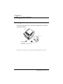
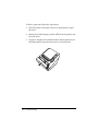
Unpacking
The illustration below shows the items included for the standard
specification printer.
Printer
PO
WE
ER
R
RO
R
P
OU APE
R
FE T
ED
Paper roll
Hexagonal
Switch cover
lock screws
(only for the serial interface)
See the note on page 1-3 for information about the hexagonal lock screws.
Setting Up the Printer 1-1
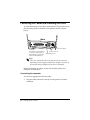
Connecting the Cables and Grounding the Printer
You can connect up to four cables to the printer. They all connect to
the connector panel on the back of the printer, which is shown
below:
FG
FG
DK
DC24V
Power supply
Interface
(The shape of the interface
connector is different from
the illustration if the printer
has a parallel interface.)
Drawer kick-out
Grounding screw
Note:
There is a caution label above the drawer kick-out connector.
Depending on the interface installed, the interface connector on
your printer may look different from the one illustrated.
Before connecting any cables, make sure both the printer and
computer are turned off.
Connecting the computer
You need an appropriate interface cable.
1. Plug the cable connector securely into the printer’s interface
connector.
1-2 Setting Up the Printer
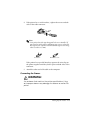
2. If the printer has a serial interface, tighten the screws on both
sides of the cable connector.
Note:
Your printer has inch-type hexagonal lock screws installed. If
your interface cable requires millimeter-type screws, replace the
inch-type screws with the enclosed millimeter-type screws using
a hex screwdriver (5 mm).
Inch screw
Millimeter screw
If the printer has a parallel interface, squeeze the wire clips on
the printer together until they lock in place on both sides of the
connector.
3. Attach the other end of the cable to the computer.
Connecting the Drawer
WARNING:
Use a drawer that matches the printer specifications. Using
an improper drawer may damage the drawer as well as the
printer.
Setting Up the Printer 1-3
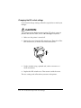
CAUTION:
Do not connect a telephone line to the drawer kick-out
connector; otherwise the printer and the telephone line may
be damaged.
Plug the drawer cable into the drawer kick-out connector on the
back of the printer next to the power supply connector.
Anschließen der Schublade
WARNUNG:
Eine für den Drucker geeignete Schublade verwenden. Bei
Verwendung einer falschen Schublade kann diese oder der
Drucker beschädigt werden.
ACHTUNG:
Kein Telefonkabel an die Schnappsteckerbuchse
anschließen, da sonst der Drucker und die Telefonkabel
beschädigt werden können.
1-4 Setting Up the Printer
Das Kabel der Schublade an die Schnappsteckerbuchse hinten am
Drucker neben dem Netßzanschluß anschließen.
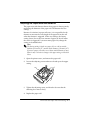
Grounding the Printer
You need a ground wire to ground your printer. Make sure the
wire is AWG 18 or equivalent.
1. Be sure the printer is turned off.
2. Connect the ground wire to the printer using one of the FG
screws on the back of the printer, as shown.
FG
FG
DK
DC24V
Connecting the Power Supply
Use the optional EPSON PS-170 or equivalent power supply for
your printer.
Setting Up the Printer 1-5
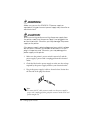
WARNING:
Make sure you use the EPSON PS-170 power supply or
equivalent. Using an incorrect power supply may cause fire or
electrical shock.
CAUTION:
When connecting or disconnecting the power supply from
the printer, make sure the power supply is not plugged into
an electrical outlet. Otherwise you may damage the power
supply or the printer.
If the power supply’s rated voltage and your outlet’s voltage
do not match, contact your dealer for assistance. Do not
plug in the power cord. Otherwise, you may damage the
power supply or the printer.
1. Make sure the printer’s power switch is turned off, and the
power supply’s power cord is unplugged from the electrical
outlet.
2. Check the label on the power supply to make sure the voltage
required by the power supply matches your electrical outlet.
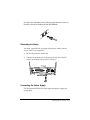
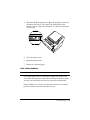
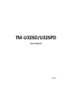
3. Plug in the power supply’s cable as shown below. Notice that
the flat side of the plug faces down.
Note:
To remove the DC cable connector, make sure the power supply’s
power cord is unplugged; then grasp the connector at the arrow and
pull it straight out.
1-6 Setting Up the Printer
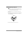
Installing or Replacing the Paper Roll
Note:
Be sure to use paper rolls that meet the specifications. Do not
use paper rolls that have the paper glued to the core, because the
printer cannot detect the paper end correctly.
1. Make sure the printer is not receiving data; otherwise, data
may be lost.
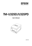
2. Open the paper roll cover by pressing the cover-open button. If
the cover-open button will not open the cover, see page 3-4 or
3-6 in Troubleshooting.
PO
WE
R
ER
RO
R
P
O AP
FFE UT ER
EEED
D
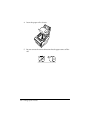
3. Remove the used paper roll core, if there is one.
Setting Up the Printer 1-7
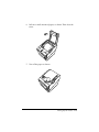
4. Insert the paper roll as shown.
PO
WE
ER
R
RO
R
P
OU APE
R
FE T
ED
5. Be sure to note the correct direction that the paper comes off the
roll.
1-8 Setting Up the Printer
6. Pull out a small amount of paper, as shown. Then close the
cover.
P
OW
ER
ER
RO
R
P
OU APE
R
FE T
ED
7. Tear off the paper as shown.
PO
WE
ER
R
RO
R
P
OU APE
FFE T R
EEED
D
Setting Up the Printer 1-9
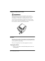
Using the Power Switch Cover
WARNING:
If an accident occurs when the power switch cover is
attached, unplug the power supply cord from the outlet
immediately. Continued use may lead to fire or shock.
You can use the enclosed power switch cover to make sure the
power switch is not pressed accidentally. If you want to use this
cover, install it as shown in the illustration below.
PO
WE
R
ER
RO
R
P
O AP
FE UT ER
FEED
ED
Self Test
The self test lets you know if your printer is operating properly. It
checks the control circuits, printer mechanisms, print quality, ROM
version, and DIP switch settings.
This test is independent of any other equipment or software.
Running the self test
1. Make sure the printer is turned off and the printer covers are
closed properly.
1-10 Setting Up the Printer
2. While holding down the FEED button, turn on the printer using
the switch on the front of the printer to begin the self test. The
self test prints the printer settings and then prints the
following, cuts the paper, and pauses. (The PAPER OUT light
blinks.)
Self test printing.
Please press the PAPER FEED button.
3. Press the FEED button to continue printing. The printer prints a
pattern using the built-in character set.
4. The self test automatically ends and cuts the paper after
printing the following:
*** completed ***
The printer is ready to receive data as soon as it completes the self
test.
Note:
If you want to pause the self test manually, press the FEED
button. Press the FEED button again to continue the self test.
Setting Up the Printer 1-11
Adjustments and Settings
TM-T88II Series printers are set up at the factory to be appropriate
for almost all users. There are, however, some settings for users
with special requirements.
Your printer has DIP switches that allow you to change
communication settings, such as handshaking and parity check, as
well as print density.
TM-T88II Series printers also have a near-end sensor for the paper.
This can warn you when the paper is almost out. If you find that
there is not enough paper remaining on the roll when the near-end
detector is triggered, you can change the near-end sensor setting.
See Appendix A, if you need to make any of these changes.
1-12 Setting Up the Printer
Chapter 2
Using the Printer
Operating the Control Panel
You can control the basic paper feeding operations of the printer
with the button on the control panel. The indicator lights help you
monitor the printer’s status.
Control Panel
POWER
ERROR
PAPER
OUT
FEED
Button
The button can be disabled by the ESC c 5 command.
Press the FEED button once to advance paper one line. You can also
hold down the FEED button to feed paper continuously.
Using the Printer 2-1
Panel lights
POWER
The POWER light is on whenever the printer is on.
ERROR
This indicates an error. See Chapter 3 for information on what to do
when this light comes on.
PAPER OUT
This light indicates the near end of the paper roll. Install a new
paper roll, and the printer will continue printing.
When the light blinks, it indicates the self-test printing standby
state or macro execution standby state when the macro execution
command is used.
2-2 Using the Printer
Chapter 3
Troubleshooting
Troubleshooting
This chapter gives solutions to some printer problems you may
have.
General problems
The lights on the control panel do not come on.
Make sure the power supply cables are correctly plugged into the
printer, the power unit, and into the power outlet.
Make sure power is supplied to the power outlet. If the outlet is
controlled by a switch or timer, use another outlet.
Printing problems
The ERROR light is on (not blinking) and nothing is printed.
If the PAPER OUT light is on, the paper roll is not installed or is at
or near the end. Install a new paper roll. See Chapter 1 for
instructions.
If the PAPER OUT light is off, make sure the printer cover is
properly closed. Press the printer cover until the cover audibly
clicks into place.
The ERROR light is blinking and the printer does not print.
First, turn off the printer and check for a paper jam. (See the paper
jam description on page 3-3.)
Troubleshooting 3-1
If there is no paper jam and the printer has been printing for quite a
while, the print head may be overheated. If the print head is
overheated, the printer will resume printing when the head has
cooled (usually within two or three minutes).
If there is no paper jam and the print head is not overheated, turn
off the printer and turn it back on after about 10 seconds. If the
ERROR light is still flashing, contact a qualified service person.
The ERROR light is off, but nothing is printed.
Try to run the self test to check that the printer works properly. See
the self test instructions in Chapter 1 to run the self test. If the self
test does not work, contact your dealer or a qualified service
person.
If the self test works properly, check the following:
1. Check the connection at both ends of the interface cable
between the printer and the computer. Also make sure this
cable meets the specifications for both the printer and the
computer.
2. The data transmission settings may be different between the
printer and computer. Make sure the printer’s DIP switch
settings for data transmission are the same as the computer’s.
You can print the printer’s interface settings using the self test.
If the printer still does not print, contact your dealer or a qualified
service person.
Printing is poor.
Paper dust on the heating element of the thermal print head can
lower the print quality. Try cleaning the print head as described
below:
3-2 Troubleshooting
Cleaning the print head
CAUTION:
After printing, the print head can be very hot. Be careful not
to touch it. Also let it cool before you clean it.
Do not damage the print head by touching it with your
fingers or any hard object.
1. Open the printer cover.
2. Clean the thermal element of the print head with a cotton swab
moistened with an alcohol solvent (ethanol, methanol, or IPA).
Radiation plate
Head
Thermal element
Paper handling problems
Paper is jammed inside the printer.
CAUTION:
Do not touch the print head because it can be very hot after
printing continuously for a long time.
Troubleshooting 3-3
To clear a paper jam, follow the steps below:
1. Turn the printer off and press the cover open button to open
the cover.
2. Remove the jammed paper, put the roll back in the printer, and
close the cover.
3. If paper is caught in the automatic cutter and the printer cover
cannot be opened, open the cutter cover as shown below.
P
OW
ER
ER
RO
R
P
O AP
FFE UT ER
EEED
D
3-4 Troubleshooting
4. Then turn the knob until you see
in the opening, as shown in
the illustration below. This returns the cutter blade to the
normal position. Also notice that there is a label near the cutter
to assist you.
ADJUSTMENT:
TURN KNOB
UNTIL YOU SEE
TRIANGLE IN OPENING
PO
WE
ER
R
RO
R
P
O U APE
R
FE T
ED
5. Close the cutter cover.
6. Open the printer cover.
7. Remove the jammed paper.
Auto cutter problems
The auto cutter is jammed.
If a foreign object, such as a push pin or paper clip, drops in the
auto cutter and causes the auto cutter to lock up, the printer enters
an error state and begins the recovery operation automatically.
If the problem is not serious, the auto cutter returns to its normal
position without any intervention by the user.
Troubleshooting 3-5
If the auto cutter does not return to its normal position by itself,
follow the steps below to correct the problem:
1. Pull the cutter cover toward you so that you can rotate the
cutter motor knob.
PO
ER
P
O AP
FE UT ER
FEED
ED
RO
WE
R
R
2. Following the instructions on the label, rotate the knob until the
appears in the hole.
ADJUSTMENT:
TURN KNOB
UNTIL YOU SEE
TRIANGLE IN OPENING
3. Close the cutter cover.
3-6 Troubleshooting
PO
WE
ER
R
RO
R
P
OU APE
R
FE T
ED
Hexadecimal Dump
This feature allows experienced users to see exactly what data is
coming to the printer. This can be useful in finding software
problems. When you turn on the hex dump function, the printer
prints all commands and other data in hexadecimal format, along
with a guide section to help you find specific commands.
To use the hex dump feature, follow these steps:
1. After you make sure the printer is off, open the cover.
2. Hold down the FEED button while you turn on the printer.
3. Close the cover.
4. Run any software program that sends data to the printer. The
printer prints “Hexadecimal Dump” and then all the codes it
receives in a two-column format. The first column contains the
hexadecimal codes and the second column gives the ASCII
characters that correspond to the codes.
Hexadecimal Dump
1B 21 00 1B 26 02 40 40 . ! . . & . @ @
1B 25 01 1B 63 34 00 1B . % . . c4 . .
41 42 43 44 45 46 47 48 ABCDEFGH
❏
A period (.) is printed for each code that has no ASCII
equivalent.
❏ During the hex dump all commands except DLE EOT and
DLE ENQ are disabled.
5. Open the cover to set the printer off line, so that it will print the
last line.
6. Close the cover and turn off the printer or reset it to turn off the
hex dump mode.
Troubleshooting 3-7
3-8 Troubleshooting
Chapter 4
Reference Information
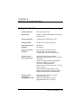
Printing Specifications
Printing method:
Thermal line printing
Dot density:
180 dpi × 180 dpi [the number of dots per
25.4 mm (1”)]
Printing direction:
Unidirectional with friction feed
Printing width:
72 mm (2.83”), 512 dot positions
Characters per line
(default):
42 (Font A)
56 (Font B)
Character spacing
(default):
0.28 mm (.01”) (2 dots) (Font A)
0.28 mm (.01”) (2 dots) (Font B)
Programmable by control command.
Printing speed —
High-speed mode:
Approximately 120 mm/second
maximum (approximately 4.72”/second
maximum)
38 lines/second maximum (computed
value for 3.18mm (1/8”) feed)
28.4 lines/second maximum
(4.23 mm (1/6”) feed, at 24 V, 28° C (82° F),
density level 2)
Speed is adjusted depending on the
applied voltage to the printer and head
temperature conditions automatically.
Printing speed —
Low-powerconsumption mode:
Approximately 16.5 lines/second
(4.23 mm feed (1/6”))
Approximately 70 mm/second
(approximately 2.76”/second)
Reference Information 4-1
Printing speed —
when a ladder bar
code is printed:
Approximately 42 mm/ second
(approximately 1.7’’/ second)
Notes:
Printing speed may be slower, depending on the data transmission
speed and the combination of control commands.
There may be variations in printing after switching the mode of the
printing speed. To prevent this for logo printing, it is recommended
that you use a downloaded bit image. (Changes in printing speed do
not occur during downloaded bit image printing).
Paper feeding speed:
Approximately 120 mm/second
(approximately 4.72”/second) continuous
paper feeding
Line spacing (default): 4.23 mm (1/6”)
Programmable by control command.
Number of characters: Alphanumeric characters: 95
International characters: 32
Extended graphics: 128 × 7 pages
(including one space page)
Kanji characters: JIS-Level 1, Level 2
(JIS X0208-1990)
Character structure:
Font A: 12 × 24 (including 2-dot spacing
horizontally)
Font B: 9 × 17 (including 2-dot spacing
horizontally)
Kanji: 24 × 24
Font A is the default
4-2 Reference Information
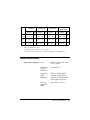
Standard
WxH
in mm (")
Double-height
Double-width
Double-width/
Double-height
CPL
WxH
in mm (")
CPL
WxH
in mm (")
CPL
WxH
in mm (")
CPL
Font A
12 x 24
1.41 x 3.39
(0.06” x .13”)
42
1.41 x 6.77
(0.06” x .27”)
42
2.82 x 3.39
(0.11” x .13”)
21
2.82 x 6.77
(0.11” x .27”)
21
Font B
9 x 17
0.99 x 2.40
(0.04” x .09”)
56
0.99 x 4.80
(0.04” x .19”)
56
1.98 x 2.40
(0.08” x .09”)
28
1.98 x 4.80
(0.08” x .19”)
28
Kanji
24 x 24
3.39 x 3.39
(0.13’’x.13’’)
21
3.39 x 6.77
(0.13’’x.27’’)
21
6.77 x 3.39
(0.27’’x.13’’)
10
6.77 x 6.77
(0.27’’x.27’’)
10
* CPL = Characters Per Line
* Space between characters is not included
* Characters can be scaled up to 64 times as large as the standard sizes.
Paper Specifications
Paper roll (single-ply): Size:
Width: 79.5 mm ± 0.5 mm
(3.13” ± 0.02”)
Maximum
outside
diameter:
83 mm (3.27”)
Paper roll
spool
diameter:
Inside: 12 mm (0.47”)
Outside: 18 mm (0.71”)
Paper must not be pasted
to the paper roll spool.
Take up
paper roll
width:
0.02’’
80± 0.5
1.0 mm 3.15’’±0.04’’
Reference Information 4-3
Electrical Characteristics
Supply voltage:
+24 VDC ± 7% (optional power supply: EPSON
PS-170)
Current
High-speed
consumption: (at mode:
24V)
Mean: Approximately 1.7A
(character font A α-N all
columns printing)
Peak: Approximately 7.7A
Low-powerconsumption
mode:
Mean: Approximately 1.2A
(Character font A α-N all
columns printing)
Peak: Approximately 6.6A
Standby:
Mean: Approximately 0.2A
Note:
Maximum 1A for drawer kick-out driving
4-4 Reference Information
Reliability
Life:
Mechanism:
15,000,000 lines
Thermal head:
100 million pulses,
100 km
Auto cutter:
1,500,000 cuts
(End of Life is defined to have reached the
end of its life when it reaches the
beginning of the Wearout Period.)
MTBF:
360,000 hours
(Failure is defined as Random Failure
occurring at the time of the Random
Failure Period.)
MCBF:
52,000,000 lines
(This is an average failure interval based
on failures relating to wearout and
random failures up to the life of 15 million
lines.)
Environmental Conditions
Temperature:
Humidity:
Operating:
5° to 45° C (41° to 113° F)
Storage:
–10° to 50° C (14° to
122° F), except for paper
Operating:
10 to 90% RH
Storage:
10 to 90% RH, except for
paper
Reference Information 4-5
4-6 Reference Information
Appendix A
DIP Switch and Paper Near End Settings
Although the factory settings are best for almost all uses, if you
have special requirements, you can change the DIP switch or paper
near end settings.
Setting the DIP Switches
DIP switch functions
Your printer has two sets of DIP switches. The functions of the
switches are shown in the following tables.
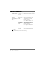
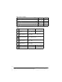
Serial interface specifications
Set 1
SW
Function
ON
OFF
1-1
Data receive error
Ignored
Prints “?”
1-2
Receive buffer capacity
45 bytes
4K bytes
1-3
Handshaking
XON/XOFF
DTR/DSR
1-4
Data word length
7 bits
8 bits
1-5
Parity check
Enabled
Disabled
1-6
Parity selection
Even
Odd
1-7
Transmission speed (See the table below.)
1-8
DIP Switch and Paper Near End Settings A-1
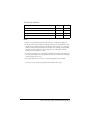
Transmission Speed
Transmission Speed (BPS)-bits per second
1-7
1-8
2400
ON
ON
4800
OFF
ON
9600
ON
OFF
19200
OFF
OFF
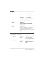
Set 2
SW
Function
ON
OFF
2-1
Handshaking (BUSY
condition)
Receive buffer full
Off line or
receive buffer full
2-2
Reserved: do not
change settings
Fixed to OFF
Selects print density
Refer to table below
2-5
Reserved: do not
change settings
Fixed to OFF
2-6
Reserved: do not
change settings
Fixed to OFF
2-7
I/F pin 6 reset signal
Enabled
Disabled
2-8
I/F pin 25 reset signal
Enabled
Disabled
2-3
2-4
A-2 DIP Switch and Paper Near End Settings
Print Density Selection
Print Density
SW 2-3
SW 2-4
1 Low power consumption mode
ON
ON
2 (Normal)
OFF
OFF
3
ON
OFF
4 (Dark)
OFF
ON
Notes:
•
With the optional RS-485 interface, DIP switches 2-7 and 2-8 are disabled.
•
Changes in DIP switch settings (excluding switches 2-7 and 2-8 interface reset
signals) are recognized only when the printer power is turned on or when the
printer is reset by using the interface. If the DIP switch setting is changed after
the printer power is turned on, the change does not take effect until the
printer is turned on again or is reset.
•
If you turn on DIP switch 2-7 or 2-8 while the printer is turned on, the printer may
be reset, depending on the signal state. DIP switches should not be changed
while the printer power is on.
•
If the print density is set to level 3 or 4, the printing will be at low speed.
•
In a low power consuption, printing speed is fixed to 70 mm/sec.
DIP Switch and Paper Near End Settings A-3
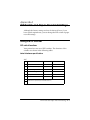
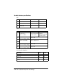
Parallel interface specifications
Set 1
SW
Function
ON
OFF
1-1
Auto line feed
Always enabled
Always disabled
1-2
Receive buffer capacity
45 bytes
4K bytes
1-3~
1-8
Undefined
—
—
SW
Function
ON
OFF
2-1
Handshaking
(BUSY condition)
• Receive buffer full
• Reading data
• Off-line
• Receive buffer full
• Reading data
2-2
Reserved
(Do not change settings)
Fixed to Off
Selects print density
Refer to table below
2-5~
2-7
Reserved
(Do not change settings)
Fixed to Off
2-8
I/F pin 31 reset signal
(Do not change settings)
Fixed to On
Set 2
2-3
2-4
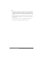
Print Density Selection
Print Density
SW 2-3
SW 2-4
1 Low power consumption mode
ON
ON
2 (Normal)
OFF
ON
3
ON
OFF
4 (Dark)
OFF
OFF
A-4 DIP Switch and Paper Near End Settings
Notes:
•
Changes in DIP switch settings (excluding switch 2-8 interface reset signal) are
recognized only when printer power is turned on or when the printer is reset
using the interface. If the DIP switch setting is changed after printer power is
turned on, the change does not take effect until the printer is turned on again
or is reset.
•
If you turn on DIP switch 2-8 while the printer is turned on, the printer may be
reset, depending on the signal state. Do not change DIP switches while the
printer power is on.
•
If the print density is set to level 3 or 4, the printing will be at low speed.
•
In a low power consumption, printing is fixed to 70 mm/sec.
DIP Switch and Paper Near End Settings A-5
Changing the DIP switch settings
If you need to change settings, follow the steps below to make your
changes:
CAUTION:
Turn off the printer before removing the DIP switch cover to
prevent an electric short, which can damage the printer.
1. Make sure the printer is turned off.
2. Remove the screw from the DIP switch cover. Then take off the
DIP switch cover, as shown in the illustration below.
DSW1
DSW2
3. Set the switches using a pointed tool, such as tweezers or a
small screwdriver.
4. Replace the DIP switch cover. Then secure it with the screw.
The new settings take effect when you turn on the printer.
A-6 DIP Switch and Paper Near End Settings
Adjusting the Paper Near End Detector
The paper near end detector detects when paper is almost gone by
measuring the diameter of the paper roll. The detector has two
settings.
Because of variations in paper roll cores, it is not possible for the
detector to measure the exact length of the paper left on the roll
when the detector is triggered. Of the two settings, the factory
setting (lower) leaves the least amount of paper on the roll when
the sensor is triggered. If you want more paper left, change the
setting as described below.
Note:
The factory setting is based on a paper roll core with an outside
diameter of 18 mm (0.71") and an inside diameter of 12 mm (0.47").
If you use a paper roll with a core with an outside diameter of more
than 18 mm, it is better to change to the upper setting, as described
below.
1. Open the printer cover, and remove the paper roll.
2. Loosen the adjusting screw and move the tab up to the upper
setting.
Screw
Tab
PO
WE
ER
R
RO
R
P
O U APE
R
FE T
ED
3. Tighten the adjusting screw, and check to be sure that the
detecting lever moves freely.
4. Replace the paper roll.
DIP Switch and Paper Near End Settings A-7
A-8 DIP Switch and Paper Near End Settings
Printed in Japan
1999.12