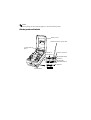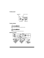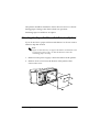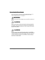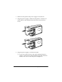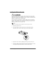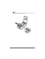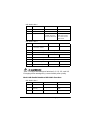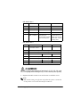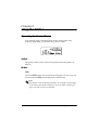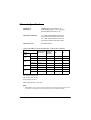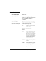
1
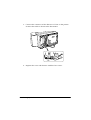
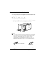
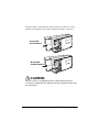
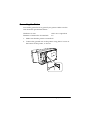
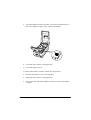
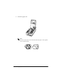
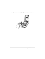
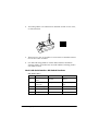
TM-U200 Series (Type A)
Operator’s Manual
Using this online operator’s guide
The words on the left side of this screen are bookmarks for all the
topics in this guide.
Use the scroll bar next to the bookmarks to find any topic you
want. Click a bookmark to instantly jump to its topic. (If you wish,
you can increase the size of the bookmark area by dragging the
dividing bar to the right.)
Use the scroll bar on the right side of this screen to move through
the text.
Use the zoom tools to magnify or reduce the page display.
Click the Find button if you want to search for a particular term.
(However, using the bookmarks is usually quicker.)
Complete online documentation for Acrobat Reader is located in the Help directory for Acrobat Reader.
Return to main menu
TM-U200 Series
(Type A)
Operator’s Manual
400898901
Note:
Everything in this manual applies to the TM-U210 printer.
Printer parts and Labels
Printer cover
Drawer kick-out connectors
Journal take-up
spool
Interface
Connector
Power connector
Model with Serial
Interface
Model with
Parallel Interface
DIP switches
Power switch
Control panel
PAPER FEED
button
PAPER OUT light
ERROR light
POWER light
Caution Labels
CAUTION:
Head cover and printer head are hot.
CAUTION:
Caution label for drawer kick-out.
Instruction Label
All rights reserved. No part of this publication may be reproduced, stored in a
retrieval system, or transmitted in any form or by any means, mechanical,
photocopying, recording, or otherwise, without the prior written permission of Seiko
Epson Corporation. No patent liability is assumed with respect to the use of the
information contained herein. While every precaution has been taken in the
preparation of this book, Seiko Epson Corporation assumes no responsibility for
errors or omissions. Neither is any liability assumed for damages resulting from the
use of the information contained herein.
Neither Seiko Epson Corporation nor its affiliates shall be liable to the purchaser of
this product or third parties for damages, losses, costs, or expenses incurred by
purchaser or third parties as a result of: accident, misuse, or abuse of this product or
unauthorized modifications, repairs, or alterations to this product, or (excluding the
U.S.) failure to strictly comply with Seiko Epson Corporation’s operating and
maintenance instructions.
Seiko Epson Corporation shall not be liable against any damages or problems arising
from the use of any options or any consumable products other than those designated
as Original Epson Products or Epson Approved Products by Seiko Epson
Corporation.
EPSON is a registered trademark of Seiko Epson Corporation.
ESC/POS is a registered trademark of Seiko Epson Corporation.
NOTICE: The contents of this manual are subject to change without notice.
Copyright © 1998 by Seiko Epson Corporation, Nagano, Japan.
i
FCC CLASS A
FCC Compliance Statement
For American Users
This equipment has been tested and found to comply with the limits for a Class A
digital device, pursuant to Part 15 of the FCC Rules. These limits are designed to
provide reasonable protection against harmful interference when the equipment is
operated in a commercial environment.
This equipment generates, uses, and can radiate radio frequency energy and, if not
installed and used in accordance with the instruction manual, may cause harmful
interference to radio communications. Operation of this equipment in a residential
area is likely to cause harmful interference, in which case the user will be required to
correct the interference at his own expense.
WARNING
The connection of a non-shielded printer interface cable to this printer will invalidate
the FCC Verification of this device and may cause interference levels which exceed
the limits established by the FCC for this equipment.
You are cautioned that changes or modifications not expressly approved by the
party responsible for compliance could void your authority to operate the
equipment.
FOR CANADIAN USERS
This Class [*] digital apparatus complies with Canadian ICES-003.
Cet appareil numérique de la classe [*] est conforme à la norme NMB-003 du
Canada.
GERÄUSCHPEGEL
Gemäß der Dritten Verordnung zum Gerätesicherheitsgesetz
(Maschinenlärminformations- Verordnung-3. GSGV) ist der arbeitsplatzbezogene
Geräusch-Emissionswert kleiner als 70 dB(A) (basierend auf ISO 7779).
ii
DECLARATION OF CONFORMITY
Product Name:
Printer
Model Name:
M119A
This printer conforms to the following Directives and Norms:
Directive 89/336/EEC
EN 55022 (1987 and 1994 2nd/1995) Class B
EN 50082-1 (1992)
IEC 801-2 (1991)
IEC 801-3 (1984)
IEC 801-4 (1988)
Directive 90/384/EEC
EN45501: (1992)
iii
Introduction
Features
The TM-U200 Series Type A printer is one-station printer for ECR and POS use that
can print the results of weighing or measuring.
TM-U200 Series (Type A) has the following 2 types.
• Two-color with a serial interface
• Two-color with a parallel interface
The main features of the TM-U200 Series Type A printer are the following:
❏
High-speed printing through logic-seeking control
❏
Excellent reliability and long life due to use of two stepping motors, one for
moving the carriage and one for paper feeding
❏
Flexible paper feed setting permits printing in accordance with any user-defined
format
❏
Command protocol based on ESC/POS ,® a widely used standard
❏
Built-in drawer kick-out interface provides capability to drive two drawers
❏
Selectable character fonts (7 x 9, 9 x 9)
❏
Semi-automatic paper loading capability
❏
AC adapter provides compact power supply
❏
Compact and light in weight
❏
Automatic Status Back (ASB) function to automatically send printer status
changes
❏
Auto cutter is installed
❏
Journal take-up spool is installed
❏
Bidirectional parallel interface in accordance with the IEEE 1284 Nibble/Byte
Modes
❏
Two-color printing (black and red)
iv
About This Manual
Setting Up and Using
❏
Chapter 1 contains information on unpacking the printer, setting it up, running
the self test, and setting the DIP switches.
❏
Chapter 2 contains information on using the printer.
❏
Chapter 3 contains troubleshooting information.
Reference
❏
Chapter 4 contains specifications.
Notes, Cautions, and Warnings
Note:
Notes have important information and useful tips on the operation of your
printer.
CAUTION:
Cautions must be observed to avoid minor injury to yourself or
damage to your equipment.
WARNING:
Warnings must be followed carefully to avoid serious bodily
injury.
v
Contents
Chapter 1 Setting Up the Printer
Unpacking . . . . . . . . . . . . . . . . . . . . . . . . . . . . . . . . . . . . . . . . . . . . . . . . . . . . . . . . . . . . 1-1
Selecting the Place . . . . . . . . . . . . . . . . . . . . . . . . . . . . . . . . . . . . . . . . . . . . . . . . . . . . . 1-1
Attaching the Paper Roll Near-End Detector (Option) . . . . . . . . . . . . . . . . . . . . . . . 1-2
Connecting the Printer to the Computer . . . . . . . . . . . . . . . . . . . . . . . . . . . . . . . . . . 1-5
Serial Interface . . . . . . . . . . . . . . . . . . . . . . . . . . . . . . . . . . . . . . . . . . . . . . . . . . . . 1-5
Parallel Interface . . . . . . . . . . . . . . . . . . . . . . . . . . . . . . . . . . . . . . . . . . . . . . . . . . . 1-6
Connecting the Printer to the Drawer . . . . . . . . . . . . . . . . . . . . . . . . . . . . . . . . . . . . . 1-6
Grounding the Printer . . . . . . . . . . . . . . . . . . . . . . . . . . . . . . . . . . . . . . . . . . . . . . . . . . 1-9
Connecting the Power Supply . . . . . . . . . . . . . . . . . . . . . . . . . . . . . . . . . . . . . . . . . . . 1-10
Installing the Ribbon Cassette . . . . . . . . . . . . . . . . . . . . . . . . . . . . . . . . . . . . . . . . . . . 1-12
Installing the Paper Roll . . . . . . . . . . . . . . . . . . . . . . . . . . . . . . . . . . . . . . . . . . . . . . . . 1-15
Running the Self Test . . . . . . . . . . . . . . . . . . . . . . . . . . . . . . . . . . . . . . . . . . . . . . . . . . . 1-20
Setting the DIP Switches . . . . . . . . . . . . . . . . . . . . . . . . . . . . . . . . . . . . . . . . . . . . . . . . 1-21
Using the Power Switch Cover . . . . . . . . . . . . . . . . . . . . . . . . . . . . . . . . . . . . . . . . . . . 1-25
Affixing the Fastening Tape (Option) . . . . . . . . . . . . . . . . . . . . . . . . . . . . . . . . . . . . . 1-26
Chapter 2 Using the Printer
Operating the Control Panel . . . . . . . . . . . . . . . . . . . . . . . . . . . . . . . . . . . . . . . . . . . . . 2-1
Switch . . . . . . . . . . . . . . . . . . . . . . . . . . . . . . . . . . . . . . . . . . . . . . . . . . . . . . . . . . . . 2-1
Button . . . . . . . . . . . . . . . . . . . . . . . . . . . . . . . . . . . . . . . . . . . . . . . . . . . . . . . . . . . . 2-1
Indicator lights . . . . . . . . . . . . . . . . . . . . . . . . . . . . . . . . . . . . . . . . . . . . . . . . . . . . 2-2
Chapter 3 Troubleshooting
Troubleshooting . . . . . . . . . . . . . . . . . . . . . . . . . . . . . . . . . . . . . . . . . . . . . . . . . . . . . . . 3-1
General Problems . . . . . . . . . . . . . . . . . . . . . . . . . . . . . . . . . . . . . . . . . . . . . . . . . . 3-1
Printing Problems . . . . . . . . . . . . . . . . . . . . . . . . . . . . . . . . . . . . . . . . . . . . . . . . . . 3-1
Removing Jammed Paper . . . . . . . . . . . . . . . . . . . . . . . . . . . . . . . . . . . . . . . . . . . 3-3
Hexadecimal Dump . . . . . . . . . . . . . . . . . . . . . . . . . . . . . . . . . . . . . . . . . . . . . . . . . . . . 3-7
Chapter 4 Reference Information
Printing Specifications . . . . . . . . . . . . . . . . . . . . . . . . . . . . . . . . . . . . . . . . . . . . . . . . . . 4-1
Character Specifications . . . . . . . . . . . . . . . . . . . . . . . . . . . . . . . . . . . . . . . . . . . . . . . . 4-2
Paper Specifications . . . . . . . . . . . . . . . . . . . . . . . . . . . . . . . . . . . . . . . . . . . . . . . . . . . . 4-3
Electrical Specifications . . . . . . . . . . . . . . . . . . . . . . . . . . . . . . . . . . . . . . . . . . . . . . . . . 4-5
Safety and EMI Standards Applied . . . . . . . . . . . . . . . . . . . . . . . . . . . . . . . . . . . . . . . 4-5
Reliability . . . . . . . . . . . . . . . . . . . . . . . . . . . . . . . . . . . . . . . . . . . . . . . . . . . . . . . . . . . . . 4-6
Environmental Conditions . . . . . . . . . . . . . . . . . . . . . . . . . . . . . . . . . . . . . . . . . . . . . . 4-7
Interface Specifications . . . . . . . . . . . . . . . . . . . . . . . . . . . . . . . . . . . . . . . . . . . . . . . . . 4-8
Drawer Kick-out Specifications. . . . . . . . . . . . . . . . . . . . . . . . . . . . . . . . . . . . . . . . . . . 4-8
vi
Chapter 1
Setting Up the Printer
Unpacking
When you unpack the TM-U200 Series Type A printer, make sure
you have these items.
Ribbon cassette
Power supply
Printer
Roll paper
Journal take-up
spool
Power switch
cover
Hexagonal lock screw (2 pcs)
(only for the printer with the serial
interface. The hexagonal lock screw
is not included for some models of this
printer.)
If any item is missing or damaged, please contact your dealer for
assistance.
Note:
See the Note on page 1-5 for information on the screws.
Selecting the Place
Place the printer on a surface that is as horizontal as possible.
Setting Up the Printer 1–1
The printer should be installed so that it does not move or vibrate
during paper cutting or the drawer kick-out operation.
Fastening tape is available as an option.
Attaching the Paper Roll Near-End Detector (Option)
If you do not have a paper roll near-end detector or do not want to
attach it, skip this section.
Note:
If you use this detector, use paper rolls with a core diameter 10.5
to 12.5 mm (0.41 to 0.47”) so that the detector senses the
remaining paper correctly.
1. Make sure the power supply is disconnected from the printer.
2. Remove four screws from the bottom of the printer; then
remove the cover.
1–2 Setting Up the Printer
3. Two spacers are included with the near-end detector. See the
illustration below, and decide whether or not you want to use
them. Use them if you want the near-end detector to be
triggered when distance A is 3 to 4 mm (0.12 to 0.16”);
otherwise it will be triggered when distance A is approximately
6 mm (0.24”).
distance A
4. Secure the paper roll near-end detector (and spacers) with two
screws. When you insert the spacers, be sure you set the
spacers in the direction shown in the illustration.
Setting Up the Printer 1–3
5. Connect the connector of the detector to CN11 on the printer.
Position the cable as shown in the illustration.
6. Replace the cover and fasten it with the four screws.
1–4 Setting Up the Printer
Connecting the Printer to the Computer
You need an appropriate serial interface or parallel interface cable
to connect your computer to the printer (null modem serial or IEEE
1284 parallel).
The Model with Serial Interface
1. Make sure the printer and computer are turned off. Then plug
the cable into the connector on the printer, as shown.
Note:
Your printer comes with inch-type hexagonal lock screws installed.
If you plan to use an interface cable that requires millimeter-type
lock screws, replace the inch-type screws with the enclosed
millimeter-type screws by using a hex screwdriver (5 mm). To
distinguish between the two types of screws, see the illustration
below.
Notch (one or more lines)
Inch-type
Millimeter-type
2. Connect the other end of the cable to the connector on your
computer.
Setting Up the Printer 1–5
The Model with Parallel Interface
1. Make sure the printer and computer are turned off. Then, plug
the cable into the connector on the printer, as shown.
Note:
Squeeze the wire clips on the printer together until they lock in
place on both sides of the connector.
2. Connect the other end of the cable to the connector on your
computer.
Connecting the Printer to the Drawer
WARNING:
Use a drawer that matches printer specifications. Using an
improper drawer may damage the drawer as well as the
printer. (See Chapter 4 “Reference Information” for
information on the drawer.
1–6 Setting Up the Printer
Plug the drawer cable into the drawer kick-out connector on the
bottom of the printer next to the computer interface connector.
Model with
Serial Interface
Model with
Parallel Interface
CAUTION:
Do not connect a telephone line to the drawer kick-out
connector; otherwise the printer and the telephone line may
be damaged.
Setting Up the Printer 1–7
Den Drucker an die Lade anschließen
Das Kabel der Lade an die Schnappsteckerbuchse (neben der
Schnittstellenbuchse) an der Unterseite des Druckers anschließen.
ACHTUNG:
Kein Telefonkabel an die Schnappsteckerbuchse
anschließen.
1–8 Setting Up the Printer
Grounding the Printer
You need a ground wire to ground your printer. Make sure the
wire meets the specification below.
Thickness of wire:
Diameter of terminal to be attached:
AWG 18 or equivalent
3.2
1. Make sure that the printer is turned off.
2. Connect the ground wire to the printer using the FG screw on
the bottom of the printer, as shown.
Setting Up the Printer 1–9
Connecting the Power Supply
This printer requires an external power supply. Be sure to use a
power supply that matches the specifications listed under
“Electrical Specifications” in Chapter 4.
WARNING:
Using an incorrect power supply may cause fire or electrical
shock.
CAUTION:
When connecting or disconnecting the power supply from
the printer, make sure the power supply is not plugged into
an electrical outlet; otherwise you may damage the power
supply or the printer.
CAUTION:
Do not connect the enclosed power supply to the EPSON
customer display DM-D101 or DM-D202. This can damage the
customer display and the power supply. However, you can
connect this power supply to the EPSON customer display
DM-D101 II or DM-D202 II.
1–10 Setting Up the Printer
1. Make sure the printer and power supply are turned off.
2. Plug the power supply’s cable into the printer’s connector as
shown below. Note that the flat side of the connector faces
down.
3. Plug the power supply’s cord into an outlet.
❏ If you ever need to remove the cable, unplug the power
supply’s cord from an outlet and then grasp the connector
firmly at the arrow mark and pull it straight out.
Setting Up the Printer 1–11
Installing the Ribbon Cassette
CAUTION:
Never turn the ribbon cassette’s feed knob in the opposite
direction of the arrow marked on the cassette; otherwise the
ribbon cassette may be damaged.
Do not replace the ribbon cassette while you are using the
printer. If the printer is receiving data when you replace the
ribbon cassette, data may be lost.
Note:
Use the EPSON ERC-38 ribbon cassette for your printer.
1. Open the printer cover.
2. Turn the ribbon cassette’s knob two or three times in the
direction of the arrow to take up any slack in the ribbon.
3. Open the auto cutter by pulling the tab up and toward you.
4. Insert the ribbon in the position shown in the illustration on the
next page and push the ribbon cassette until it clicks.
1–12 Setting Up the Printer
Note:
Make sure the ribbon is installed between the print head and the
platen without wrinkles or creases.
Setting Up the Printer 1–13
5. Turn the ribbon cassette’s knob 2 or 3 times in the direction of
the arrow again to take up any slack in the ribbon.
6. Close the auto cutter by using the tab.
7. Close the printer cover.
To remove the ribbon cassette, follow the steps below.
1. Be sure the printer is not receiving data.
2. Open the auto cutter by using the tab.
3. Lift up the left side of the ribbon cassette to remove the ribbon
cassette.
1–14 Setting Up the Printer
Installing the Paper Roll
CAUTION:
Be sure the printer is not receiving data when you replace a
paper roll. If there is data, printing will start.
Notes:
Be sure to use roll paper that meets the specifications. (See “Paper
Specifications” in Chapter 4.
If you use roll paper with the paper glued or taped to the core, the
core may be pulled into a paper feed path, which may cause a paper
jam or lock the paper feed mechanism.
When you use a paper roll with the end attached to the core, use the
optional paper roll near-end detector or replace the paper roll when
the mark that indicates you are near the end of the paper roll
appears.
1. Using scissors, cut the leading edge of the paper roll as shown
below.
2. Turn on the printer and open the printer cover.
Setting Up the Printer 1–15
3. Insert the paper roll.
Note:
Be sure to note the correct direction that the paper comes off the
roll, as shown below.
1–16 Setting Up the Printer
4. Open the auto cutter by pulling the tab up and toward you.
Setting Up the Printer 1–17
5. Hold both edges of the paper and insert it straight into the
paper slot. The printer feeds the paper automatically.
6. When using a 2-ply roll paper, remove the journal take-up
spool from the printer, and insert the end of the paper into the
spool as shown below. Be sure that length of A is between 40
and 60 mm (1.58 and 2.36”) and the left side of the paper is
aligned with the spool’s flange.
Flange
A
Journal take-up
spool
Journal paper
1–18 Setting Up the Printer
7. Insert the journal take-up spool in the printer.
8. Cut the receipt paper (when using a 2-ply roll paper) on the
manual cutter.
Receipt paper
Tab
9. Close the auto cutter by using the tab. Be sure to check again
that the left side of the paper is aligned with the spool’s flange
as shown below.
10. Close the printer cover.
To remove the paper roll, follow the steps below.
1. Be sure the printer is not receiving data and open the printer
cover.
Setting Up the Printer 1–19
2. Cut the journal and receipt paper as shown in the illustration
below.
Cut here
3. Remove the paper take-up spool from the printer.
4. Remove the paper roll from the printer.
5. Press the FEED button to remove the remaining paper.
Note:
Do not pull the remaining paper in the opposite direction of
paper feeding.
Running the Self Test
Any time you want to check the performance of your printer you
can run the self test described below. This shows whether your
printer is working correctly. It is independent of any other
equipment or software.
1–20 Setting Up the Printer
Note:
Be sure to install the ribbon cassette and the paper roll before
you run the self test.
1. To perform the self test, hold down the FEED button while you
turn on the printer with the power switch.
2. The printer prints the current printer settings, and then the
PAPER OUT light blinks to indicate that the printer is in the test
printing standby state.
3. Press the FEED button to start the second part of the test, in
which the printer prints a pattern using the built-in character
set.
4. After the printer completes a certain number of lines, it prints
the following:
*** completed ***
Then it enters the normal mode.
Note:
If you want to pause the self test manually, press the FEED
button. Press the FEED button again to continue the self test.
Setting the DIP Switches
CAUTION:
Turn off the printer while removing the DIP switch cover to
prevent an electrical short, which can damage the printer.
You can change your serial interface and print column settings by
changing the DIP switch settings.
1. Make sure the printer is off.
Setting Up the Printer 1–21
2. Turn the printer over and remove the DIP switch access cover,
as shown below.
3. There are two sets of switches. Use tweezers or another narrow
tool to move the switches.
4. Use the following tables to set the DIP switches. Numbers
starting with 1 are in the first set, and numbers starting with 2
are in the second.
Model with Serial Interface DIP-Switch Functions
DIP Switch Set 1
Switch
Function
ON
OFF
1-1
Data reception
error
Ignored
Prints”?”
1-2
Receive buffer
capacity
40 bytes
Approximately 1K
byte
1-3
Handshaking
XON/XOFF
DTR/DSR
1-4
Word length
7 bits
8 bits
1-5
Parity check
Yes
No
1–22 Setting Up the Printer
DIP Switch Set 1
Switch
Function
ON
OFF
1-6
Parity selection
Even
Odd
1-7
Baud rate
4800 BPS
9600 BPS
1-8
Busy condition
Sets the printer to
go BUSY when the
receive buffer is full
Sets the printer to go
BUSY when it is off
line or the receive
buffer is full
DIP Switch Set 2
Switch
Function
ON
OFF
2-1
Print column selection
7 × 9 font/9 × 9 font
42/35
40/33
2-2
Internal use. Setting must not be changed. (Fixed to ON)
2-3
Internal use. Setting must not be changed. (Fixed to OFF)
2-4
Undefined
2-5
Internal use. Setting must not be changed. (Fixed to ON)
2-6
Internal use. Setting must not be changed. (Fixed to OFF)
2-7
I/F pin 6 reset signal
Enabled
Disabled
2-8
I/F pin 25 reset signal
Enabled
Disabled
CAUTION:
Do not change the settings of switches 2-2, 2-3, 2-5, and 2-6.
Changing these settings may cause inferior print quality.
Model with Parallel Interface DIP-Switch Functions
DIP Switch Set 1
Switch
Function
ON
OFF
1-1
Auto-line feed
Enabled
Disabled
1-2
Receive buffer
capacity
40 bytes
Approximately 1K
byte
1-3
Undefined
Setting Up the Printer 1–23
DIP Switch Set 1
Switch
Function
1-4
Undefined
1-5
Undefined
1-6
Undefined
1-7
Undefined
1-8
Handshaking
(BUSY condition)
ON
OFF
Sets the printer to go
BUSY when the
receive buffer is full or
when reading data
Sets the printer to
go BUSY when it is
off line, the receive
buffer is full, or when
reading data
DIP Switch Set 2
Switch
Function
ON
OFF
2-1
Print column selection
7 × 9 font/9 × 9 font
42/35
40/33
2-2
Internal use. Setting must not be changed. (Fixed to ON)
2-3
Internal use. Setting must not be changed. (Fixed to OFF)
2-4
Undefined
2-5
Internal use. Setting must not be changed. (Fixed to ON)
2-6
Internal use. Setting must not be changed. (Fixed to OFF)
2-7
Undefined
2-8
Internal use. Setting must not be changed. (Fixed to ON)
CAUTION:
Do not change the settings of switches 2-2, 2-3, 2-5, 2-6, and
2-8. Changing these settings may cause inferior print quality.
5. Replace the DIP switch cover and secure it with the screw.
Note:
DIP switch settings are effective only when the power is turned on
or the printer is reset with the interface connector.
1–24 Setting Up the Printer
Using the Power Switch Cover
You can use the provided power switch cover to protect the power
switch from accidental or improper operation. Attach the cover as
shown in the illustration below.
You can turn the power on or off with the switch cover attached by
inserting a pointed object (like a ball point pen) through either of
the two small holes on the switch cover.
WARNING:
If an accident occurs when the power switch cover is
attached, unplug the power supply cord from the outlet
immediately.
Setting Up the Printer 1–25
Affixing the Fastening Tape (Option)
Two sets of tape are included as an option to fasten your printer to
a countertop or other surface. Follow the steps below:
1. Clean the countertop or other surface where the printer will be
installed.
2. Peel the green backing paper off of one side of each of the two
sets of tape and affix them to the bottom of the printer, as
shown below.
3. Peel the green backing paper off of the other side of the tape.
4. Press the printer onto the countertop; it will be held firmly in
place by the fastening tape.
1–26 Setting Up the Printer
Chapter 2
Using the Printer
Operating the Control Panel
You can feed paper with the button on the control panel. The
indicator lights help you monitor the printer’s status.
Switch
The power switch on the front of the printer turns the printer on
and off.
Button
FEED
Press the FEED button once to advance roll paper one line. You can
also hold down FEED to feed the paper continuously.
Note:
This button can be disabled by the ESC c 5 command, but depending
on the setting of GS z 0 command, it can work while replacing the
paper roll even if it has been disabled.
Using the Printer 2-1
Indicator lights
The control panel lights provide information on printer conditions.
POWER (Green)
The POWER light is on when printer power is on.
PAPER OUT (Red)
This light is on when the paper roll is at the end or near the end.
This light blinks in the following cases. When it blinks, press the
FEED button.
❏ In the self-test standby mode
Note:
The paper near-end detector is an option.
ERROR (Red)
This light is on when the printer is off line. It blinks to indicate an
error condition.
The blinking pattern shown below indicates that the temperature
of the print head is too high. The printer recovers automatically
and resumes printing when the head cools.
Approximately 160 ms
If the printer stops working and the ERROR light is blinking, turn
the printer off, check for jammed paper, and remove it by following
the instructions on page 3-3, if necessary. Then turn the printer
back on. If the printer still does not work, unplug the power supply
cord from the outlet immediately; then contact a qualified service
person.
2-2 Using the Printer
CAUTION:
The print head becomes very hot during printing. Allow it to
cool before you reach into the printer.
Note:
The power switch and FEED button can also be used to start the
self test.
Using the Printer 2-3
Chapter 3
Troubleshooting
Troubleshooting
This chapter gives solutions to some of the more common printer
problems.
General problems
The lights on the control panel do not come on.
Make sure the power supply cables are correctly plugged into the
printer, the AC adapter, and to the power outlet.
Make sure power is supplied to the power outlet. If the outlet is
controlled by a switch or timer, use another outlet.
Printing problems
The ERROR light is blinking and the printer does not print.
First, turn off the printer and check for a paper jam. (See the paper
jam description on page 3-3.)
If there is no paper jam and the printer has been printing for quite a
while, the print head may be overheated. If the print head is
overheated, the printer will resume printing when the head has
cooled (usually within two or three minutes).
If there is no paper jam and the print head is not overheated, turn
off the printer and turn it back on after about 10 seconds. If the
printer still does not work, unplug the power supply cord from the
outlet immediately. Then contact a qualified service person.
Troubleshooting 3-1
The ERROR light is off, but nothing is printed.
Try to run the self test to check that the printer works properly. See
the self test instructions in Chapter 1 to run the self test. If the self
test does not work, contact your dealer or a qualified service
person.
If the self test works properly, check the following:
1. Check the connection at both ends of the interface cable
between the printer and the computer. Also make sure this
cable meets the specifications for both the printer and the
computer.
2. The data transmission settings may be different between the
printer and computer. Make sure the printer’s DIP switch
settings for data transmission are the same as the computer’s.
You can print the printer’s interface settings using the self test.
If the printer still does not print, contact your dealer or a qualified
service person.
The printer sounds like it is printing, but nothing is printed.
The ribbon cassette may not be installed properly. See the
instructions in Chapter 1.
The ribbon may be worn out. Replace the ribbon cassette as
described in Chapter 1.
If the printer still does not print, contact your dealer or a qualified
service person.
The printout is faint.
The ribbon may be worn out. Replace the ribbon cassette as
described in Chapter 1.
3-2 Troubleshooting
A line of dots is missing in the printout.
The print head may be damaged. Stop printing and contact your
dealer or a qualified service person.
Removing jammed paper
Follow these steps to clear a paper jam:
CAUTION:
The print head becomes very hot during printing. Allow it to
cool before you reach into the printer.
1. Open the printer cover.
2. Cut the journal and receipt paper as shown in the illustration
below.
Cut here
Troubleshooting 3-3
3. Remove the paper roll from the printer.
4. Open the auto cutter by pulling the tab up and toward you.
5. Remove the jammed paper by pulling it in the direction of
paper feeding.
Note:
Do not pull the jammed paper in the opposite direction of paper
feeding.
6. If paper still remains in the printer, follow the steps below.
7. Remove the ribbon cassette.
3-4 Troubleshooting
8. Loosen the screw securing the print head cover. Turn the screw
only until you can tilt it as shown in the illustration.
Note:
Do not remove the screw from the print head cover.
Troubleshooting 3-5
9. Lift up the print head cover.
10. Remove all the jammed paper.
Note:
Do not pull the jammed paper in the opposite direction of paper
feeding.
11. Replace the print head cover and secure it with the screw.
12. Replace the ribbon cassette and close the auto cutter.
3-6 Troubleshooting
13. If the auto cutter blade is not in its normal position (if you can
see the blade in the auto cutter slit, the blade is not in the
normal position), insert a screwdriver to the right side of the
auto cutter and turn the gear inside to move the blade to the
normal position.
Slit
14. Replace the paper roll and close the printer cover.
Hexadecimal Dump
This feature allows experienced users to see exactly what data is
coming to the printer. This can be useful in finding software
problems. When you turn on the hex dump function, the printer
prints all commands and other data in hexadecimal format along
with a guide section to help you find specific commands.
Troubleshooting 3-7
To use the hex dump feature, follow these steps:
1. After you make sure that the printer is off, set DIP switch 1-2 to
ON.
2. Turn on the printer while you hold down the FEED button; then
release and press the FEED button quickly.
Note:
Releasing and pressing the FEED button should be performed
before the printer finishes initializing; otherwise the printer
begins the self test.
3. When the printer enters the hex dump mode, it prints
“Hexadecimal Dump.”
4. Run any software program that sends data to the printer. The
printer prints all the codes it receives in a two-column format.
The first column contains the hexadecimal codes and the
second column gives the ASCII characters that correspond to
the codes.
Hexadecimal Dump
1B 21 00 1B 26 02 40 40 : . ! . . & . @ @
1B 25 01 1B 63 34 00 1B : . % . . c4 . .
41 42 43 44 45 46 47 48 : ABCDEFGH
❏
A period (.) is printed for each code that has no ASCII
equivalent.
❏ During the hex dump all commands except DLE EOT and
DLE ENQ are disabled.
5. When the printing finishes, turn off the printer or reset it to
turn off the hex dump mode.
6. If you changed the DIP switch 1-2, set it back to OFF.
3-8 Troubleshooting
Chapter 4
Reference Information
Printing Specifications
Printing method:
Serial impact dot-matrix
Head wire
configuration:
9-pin serial configuration
Printing direction:
Bi-directional, logic-seeking
Characters/line
(default):
See table on page 4-2.
Character spacing
(default)
Fonts A and B:
See table on page 4-2.
Printing speed:
Approximately 3.5 lines/second (40
columns, 16 characters/inch)
Approximately 6.4 lines/second (16
columns, 16 characters/inch)
(excluding data transmission time and
processing time)
Note:
When printing exceeds the allowable print duty cycle, the printer
automatically stops printing. In this case, the printing speed
described above is not guaranteed.
When selecting red-color or 2-color (black/red) combination
printing, the printing speed goes down, compared to black-color
printing. It is caused by the switching operation in the printer.
Reference Information 4-1
Character Specifications
Number of
characters:
Alphanumeric characters: 95
Extended graphics: 128 x 5 pages,
International characters: 32
Character structure:
7 x 9 (the total number of dots in
horizontal: 400 in half dot units)
9 x 9 (the total number of dots in
horizontal: 400 in half dot units)
Character size:
See table below.
Character Sizes, Character Spacing, Character Columns
Character structure
WxH
(mm)
Character size
W x H (mm)
Character
spacing
Dot space
CPL
CPI
ANK
1.2 x 3.1
3 half dots
40
16
Graphics
1.7 x 3.1
0
40
16
ANK
1.6 x 3.1
3 half dots
33
13.3
Graphics
2.0 x 3.1
0
33
13.3
ANK
1.2 x 3.1
2 half dots
42
17.8
Graphics
1.6 x 3.1
0
42
17.8
ANK
1.6 x 3.1
2 half dots
35
14.5
Graphics
1.9 x 3.1
0
35
14.5
Character
7x9
9x9
7x9
9x9
CPL = Characters per line
CPI = Characters per inch
LPS = Lines per second
ANK = Alphanumeric characters
Note:
• The default is 7 x 9 font. The dot spacing between characters for 3-dot spacing in half
dot units and 2-dot spacing in half dot units depend on the DIP switch setting.
4-2 Reference Information
Paper Specifications
Paper feed method:
Friction feed
Paper feed pitch:
Default 4.233 mm (1/6 inch)
Can be set in units of 0.176 mm (1/144
inch) by the ESC 2 and ESC 3
commands.
Paper feed speed:
Approximately 25 lines/second (4.17
inches/second) (continuous feeding)
Paper size and weight:
Normal paper (single-ply)
Size:
Width 76 mm ± 0.5 mm
(3.0" ± 0.02")
Maximum
outside
diameter:
83 mm (3.27")
Core:
Paper rolls that have the
paper glued or taped to
the core can cause a paper
jam. If you use a paper
roll with the paper glued
or taped to the core, be
sure to use the optional
near end detector.
Thickness:
0.06 to 0.085 mm (.0024 to
.0033")
Weight:
52.3 to 64.0 g/m2 (13.9 to
17 lbs) (45 to 55 Kg (20.41
to 24.94 lbs)/1000 sheets/
1091 mm ✕ 788mm
(43.00" ✕ 31.02")
Reference Information 4-3
Pressure sensitive paper
Maximum 1 original + 1 copy
Size:
Width 76 mm ± 0.5 mm
(3.0" ± 0.02")
Maximum
outside
diameter:
83 mm (3.27")
Thickness:
0.05 to 0.08 mm (.0020 to
.0031")
(Total thickness should
be a 0.2 mm or less
combination of 0.05 to
0.08 mm sheet.)
Recommend MITSUBISHI PAPER
-ed paper: MILLS, LTD.
Non-carbon paper
(blue color)
Top and middle sheets:
N40
(thickness: 0.06 mm,
weight: 47.2 g/m2 )
Bottom sheet: N60
(thickness: 0.08 mm,
weight: 68.0 g/m2)
4-4 Reference Information
Electrical Specifications
Packaged AC adapter:
One of the following 5 AC adapters is
selected, depending on local power:
Factory setting
Voltage
Manufacturer’s Number
Japan
100 V ± 10 %, 50/60Hz
PA-6508
North America
120 V ± 10 %, 60 Hz
PB-6509
Europe (Germany)
230 V ± 10 %, 50 Hz
PB-6510
Europe (England)
230 V ± 10 %, 50 Hz
PA-6511
Australia
240 V ± 10 %, 50 Hz
PA-6513
Note:
The power supply may not be included with the printer with
serial interface.
Voltage output range
Current consumption
(excluding driving
drawer kickout)
24 - 30 V at 1.2 A
Operating :
Average 43 W
Standby:
Average 6 W
Safety and EMI Standards Applied
(EMC is measured using Seiko Epson’s AC adapter provided with the
printer)
Europe:
North America:
CE marking:
EN55022
EN50082-1
EN45501
Safety standard:
TÜV
EMI:
FCC class A
Safety standard:
UL1950-2TH-D3
C-UL
Reference Information 4-5
Reliability
Life:
Mechanism 7,500,000 lines
Print head:
150 million characters
(at an average of 2 dots/wire per
character.)
Auto cutter: 800,000 cuts
End of life is defined as the point at
which the printer reaches the
beginning of the Wearout Period.
Recommended paper must be used.
MTBF:
180,000 hours
Failure is defined as Random failure
occurring at the time of the Random
Failure Period.
MCBF:
18,000,000 lines
This is an average failure interval
based on failures relating to wearout
and random failures up to the life of
7.5 million lines.
4-6 Reference Information
Environmental Conditions
Temperature
Operating:
0 to 50 ° C (32 to 122 ° F)
(when the temperature is 34 ° C or more,
there is a limitation for the humidity.
Refer to the figure in the next page.)
Storage:
–10 to 50 ° C (14 to 122° F)
(except for paper, and a ribbon)
Humidity
Operating:
10 to 90% RH
Storage:
10 to 90% RH
(except for paper and a ribbon)
Operating environment range
34 ° C, 90%
Relative humidity
90
80
40 ° C, 65%
60
40
50 ° C, 35%
20
10
0
0
10
20
50
40
30
Environment temperature [ ° C]
Reference Information 4-7
Interface Specifications
Serial interface:
RS-232 compatible or RS-485 compatible
Parallel interface:
IEEE 1284 compatible (Nibble/Byte
Modes)
Note:
The interface is a factory-installed option. One of the following
interfaces is already installed: RS-232, RS-485, or parallel.
See the EPSON TM-U200 Series (Type A) Specification for details.
Drawer Kick-out Specifications
‚P
‚U
Pin No.
Signal Name
Direction
1
Frame GND
—
2
Drawer kick-out drive signal 1
Output
3
Drawer open/close signal
Input
4
+24 V
—
5
Drawer kick-out drive signal 2
Output
6
Signal GND
—
Output signal voltage:
Approximately 24 V
Output current:
1 A or less
Solenoid resistance:
24 Ω or more
4-8 Reference Information