1
Cat. No. W480-E1-05
SYSMAC CP Series
CP1E-E@@SD@-@
CP1E-N@@S@D@-@
CP1E-E@@D@-@
CP1E-N@@D@-@
CP1E-NA@@D@-@
CP1E CPU Unit Software
USER’S MANUAL
OMRON, 2009
All rights reserved. No part of this publication may be reproduced, stored in a retrieval system, or transmitted, in any form, or
by any means, mechanical, electronic, photocopying, recording, or otherwise, without the prior written permission of
OMRON.
No patent liability is assumed with respect to the use of the information contained herein. Moreover, because OMRON is constantly striving to improve its high-quality products, the information contained in this manual is subject to change without
notice. Every precaution has been taken in the preparation of this manual. Nevertheless, OMRON assumes no responsibility
for errors or omissions. Neither is any liability assumed for damages resulting from the use of the information contained in
this publication.
SYSMAC CP Series
CP1E-E@@SD@-@
CP1E-N@@S@D@-@
CP1E-E@@D@-@
CP1E-N@@D@-@
CP1E-NA@@D@-@
CP1E CPU Unit Software
User’s Manual
Revised November 2012
Introduction
Thank you for purchasing a SYSMAC CP-series CP1E Programmable Controller.
This manual contains information required to use the CP1E. Read this manual completely and be sure
you understand the contents before attempting to use the CP1E.
Intended Audience
This manual is intended for the following personnel, who must also have knowledge of electrical systems (an electrical engineer or the equivalent).
• Personnel in charge of installing FA systems
• Personnel in charge of designing FA systems
• Personnel in charge of managing FA systems and facilities
Applicable Products
z CP-series CP1E CPU Units
• Basic Models CP1E-E
(S)D
-
A basic model of CPU Unit that support basic control applications using instructions such as
basic, movement, arithmetic, and comparison instructions.
• Application Models CP1E-N/NA
(S
)D
-
An application model of CPU Unit that supports connections to Programmable Terminals, inverters, and servo drives.
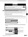
The CP Series is centered around the CP1H, CP1L, and CP1E CPU Units and is designed with the
same basic architecture as the CS and CJ Series.
Always use CP-series Expansion Units and CP-series Expansion I/O Units when expanding I/O
capacity. I/O words are allocated in the same way as for the CPM1A/CPM2A PLCs, i.e., using fixed
areas for inputs and outputs.
CP1E CPU Unit Software User’s Manual(W480)
1
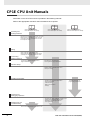
CP1E CPU Unit Manuals
Information on the CP1E CPU Units is provided in the following manuals.
Refer to the appropriate manual for the information that is required.
This Manual
CP1E CPU Unit Hardware
User’s Manual(Cat. No. W479)
CP1E CPU Unit Software
User’s Manual(Cat. No. W480)
CP1E CPU Unit Instructions
Reference Manual(Cat. No. W483)
Mounting and
1 Setting Hardware
· Names and specifications of the parts of all Units
· Basic system configuration for each CPU Unit
· Connection methods for Expansion I/O Units
and Expansion Units
2 Wiring
· Wiring methods for the power supply
· Wiring methods between external I/O devices
and Expansion I/O Units or Expansion Units
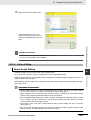
Connecting
3 Online to the PLC
Connecting Cables for CX-Programmer
Support Software
Procedures for connecting the
CX-Programmer Support Software
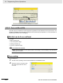
4 Software Setup
Software setting methods for the CPU
Units (PLC Setup)
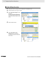
5 Creating the Program
· Program types and basic information
· CPU Unit operation
· Internal memory
· Built-in CPU functions
· Settings
Detailed information on
programming instructions
Checking and
6 Debugging Operation
Maintenance and
· Checking I/O wiring, setting the Auxiliary Area
settings, and performing trial operation
· Monitoring and debugging with the
CX-Programmer
7 Troubleshooting
Error codes and remedies if a problem occurs
2
CP1E CPU Unit Software User’s Manual(W480)
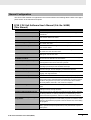
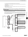
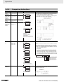
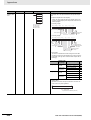
Manual Configuration
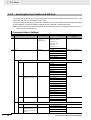
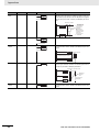
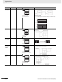
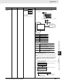
The CP1E CPU manuals are organized in the sections listed in the following tables. Refer to the appropriate section in the manuals as required.
CP1E CPU Unit Software User’s Manual (Cat. No. W480)
(This Manual)
Section
Contents
Section 1 Overview
This section gives an overview of the CP1E, describes its application
procedures.
Section 2 CPU Unit Memory
This section describes the types of internal memory in a CP1E CPU
Unit and the data that is stored.
Section 3 CPU Unit Operation
This section describes the operation of a CP1E CPU Unit.
Section 4 Programming Concepts
This section provides basic information on designing ladder programs
for a CP1E CPU Unit.
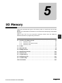
Section 5 I/O Memory
This section describes the types of I/O memory areas in a CP1E CPU
Unit and the details.
Section 6 I/O Allocation
This section describes I/O allocation used to exchange data between
the CP1E CPU Unit and other units.
Section 7 PLC Setup
This section describes the PLC Setup, which are used to perform basic
settings for a CP1E CPU Unit.
Section 8 Overview and Allocation
of Built-in Functions
This section lists the built-in functions and describes the overall application flow and the allocation of the functions.
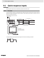
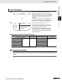
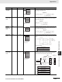
Section 9 Quick-response Inputs
This section describes the quick-response inputs that can be used to
read signals that are shorter than the cycle time.
Section 10 Interrupts
This section describes the interrupts that can be used with CP1E PLCs,
including input interrupts and scheduled interrupts.
Section 11 High-speed Counters
This section describes the high-speed counter inputs, high-speed
counter interrupts, and the frequency measurement function.
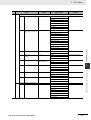
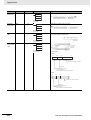
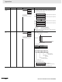
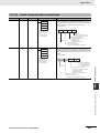
Section 12 Pulse Outputs
This section describes positioning functions such as trapezoidal control,
jogging, and origin searches.
Section 13 PWM Outputs
This section describes the variable-duty-factor pulse (PWM) outputs.
Section 14 Serial Communications
This section describes communications with Programmable Terminals
(PTs) without using communications programming, no-protocol communications with general components, and connections with a ModbusRTU Easy Master, Serial PLC Link, and host computer.
Section 15 Analog I/O Function
This section describes the built-in analog function for NA-type CPU
Units.
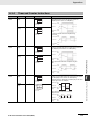
Section 16 Built-in Functions
This section describes PID temperature control, clock functions, DM
backup functions, security functions.
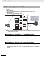
Section 17 Ethernet Option Board
This section gives an overview of the Ethernet Option Board, describes
its setting methods, I/O memory allocations, troubleshooting, how to
connect the CX-Programmer, and how to install an Ethernet network.
Section 18 Operating the Programming Device
This section describes basic functions of the CX-Programmer, such as
using the CX-Programmer to write ladder programs to control the CP1E
CPU Unit, to transfer the programs to the CP1E CPU Unit, and to debug
the programs.
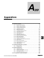
Appendices
The appendices provide lists of programming instructions, the Auxiliary
Area, cycle time response performance, PLC performance at power
interruptions.
CP1E CPU Unit Software User’s Manual(W480)
3
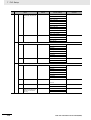
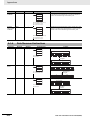
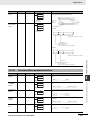
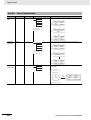
CP1E CPU Unit Hardware User’s Manual (Cat. No. W479)
Section
Contents
Section 1 Overview and Specifications
This section gives an overview of the CP1E, describes its features, and
provides its specifications.
Section 2 Basic System Configuration and Devices
This section describes the basic system configuration and unit models
of the CP1E.
Section 3 Part Names and Functions This section describes the part names and functions of the CPU Unit,
Expansion I/O Units, and Expansion Units in a CP1E PLC .
Section 4 Programming Device
This section describes the features of the CX-Programmer used for programming and debugging PLCs, as well as how to connect the PLC with
the Programming Device by USB.
Section 5 Installation and Wiring
This section describes how to install and wire CP1E Units.
Section 6 Troubleshooting
This section describes how to troubleshoot problems that may occur
with a CP1E PLC, including the error indications provided by the CP1E
Units.
Section 7 Maintenance and Inspection
This section describes periodic inspections, the service life of the Battery, and how to replace the Battery.
Section 8 Using Expansion Units
and Expansion I/O Units
This section describes application methods for Expansion Units.
Appendices
The appendices provide information on dimensions, wiring diagrams,
and wiring serial communications for the CP1E.
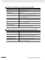
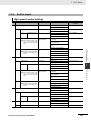
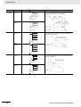
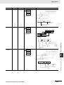
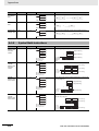
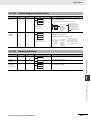
CP1E CPU Unit Instructions Reference Manual (Cat. No. W483)
Section
4
Contents
Section 1 Summary of Instructions
This section provides a summary of instructions used with a CP1E CPU
Unit.
Section 2 Instruction
This section describes the functions, operands and sample programs of
the instructions that are supported by a CP1E CPU Unit.
Section 3 Instruction Execution
Times and Number of Steps
This section provides the execution times for all instructions used with a
CP1E CPU Unit.
Section 4 Monitoring and
Computing the Cycle Time
This section describes how to monitor and calculate the cycle time of a
CP1E CPU Unit that can be used in the programs.
Appendices
The appendices provide a list of instructions by Mnemonic and ASCII
code table for the CP1E CPU Unit.
CP1E CPU Unit Software User’s Manual(W480)
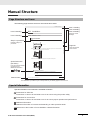
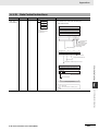
Manual Structure
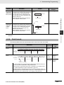
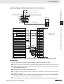
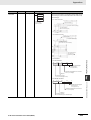
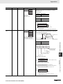
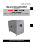
Page Structure and Icons
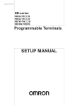
The following page structure and icons are used in this manual.
Installation
Level 1 heading
Level 2 heading
Level 3 heading
Installation Location
Gives the current
headings.
5 Installation and wiring
Level 2 heading
Level 3 heading
5-2
5-2-1
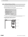
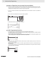
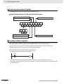
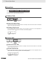
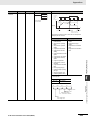
DIN Track Installation
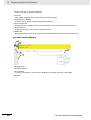
1
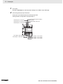
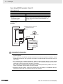
Use a screwdriver to pull down the DIN Track mounting pins from the back of the Units to release
them, and mount the Units to the DIN Track.
Indicates a step in a
procedure.
DIN Track mounting pins
5
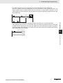
Fit the back of the Units onto the DIN Track by catching the top of the Units on the Track and then
pressing in at the bottom of the Units, as shown below.
DIN Track
3
5-2-1 Installation Location
Release
2
5-2 Installation
Step in a procedure
Page tab
Gives the number
of the section.
Press in all of the DIN Track mounting pins to securely lock the Units in place.
Special Information
(See below.)
Icons are used to indicate
precautions and
additional information.
DIN Track mounting pins
Precautions for Correct Use
Tighten terminal block screws and cable screws to the following torques.
M4: 1.2 N·m
M3: 0.5 N·m
Manual name
CP1E CPU Unit Hardware User’s Manual(W479)
5-3
This illustration is provided only as a sample and may not literally appear in this manual.
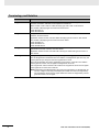
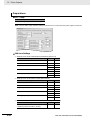
Special Information
Special information in this manual is classified as follows:
Precautions for Safe Use
Precautions on what to do and what not to do to ensure using the product safely.
Precautions for Correct Use
Precautions on what to do and what not to do to ensure proper operation and performance.
Additional Information
Additional information to increase understanding or make operation easier.
References to the location of more detailed or related information.
CP1E CPU Unit Software User’s Manual(W480)
5
Terminology and Notation
Term
E-type CPU Unit
Description
A basic model of CPU Unit that support basic control applications using instructions such
as basic, movement, arithmetic, and comparison instructions.
Basic models of CPU Units are called “E
(S)-type CPU Units” in this manual.
The models of E
(S)-type CPU Units are shown below.
CP1E-E
D
-
CP1E-E
SD
-
N-type CPU Unit
An application model of CPU Unit that supports connections to Programmable Terminals,
inverters, and servo drives.
Application models of CPU Units are called “N
(S)-type CPU Units” in this manual.
The models of N
(S)-type CPU Units are shown below.
CP1E-N
D
-
CP1E-N
SD
-
CP1E-N
S1D
-
NA-type CPU Unit
An application model of CPU Unit that supports built-in analog and connections to Programmable Terminals, inverters, and servo drives.
Application models of CPU Units with built-in analog are called “NA-type CPU Units” in
this manual.
CX-Programmer
A programming device that applies for programming and debugging PLCs.
The CX-Programmer includes the Micro PLC Edition CX-Programmer (CX-One Lite), the
CX-Programmer (CX-One) and the CX-Programmer for CP1E.
This manual describes the unique applications and functions of the Micro PLC Edition
CX-Programmer version 9.03 or higher/CX-Programmer for CP1E.
“CX-Programmer” refers to the Micro PLC Edition CX-Programmer version 9.03 or higher/
CX-Programmer for CP1E in this manual.
Note E20/30/40(S) and N20/30/40(S
) CPU Units are supported by CX-Programmer version 8.2 or higher. E10/14(S), N14/60(S
) and NA20 CPU Units are supported by
CX-Programmer version 9.03 or higher. E60S CPU Units are supported by CX-Programmer version 9.42 or higher.
6
CP1E CPU Unit Software User’s Manual(W480)
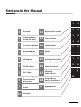
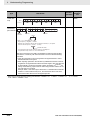
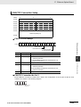
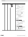
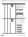
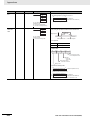
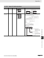
Sections in this Manual
1
2
Overview
Internal Memory
in the CPU Unit
11
12
1
11
2
12
3
13
4
14
5
15
High-speed Counters
Pulse Outputs
3
CPU Unit Operation
13
PWM Outputs
4
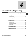
Understanding
Programming
14
Serial
Communications
6
16
5
I/O Memory
15
Analog I/O Function
7
17
6
16
8
18
I/O Allocation
Other Functions
9
APP
7
PLC Setup
17
Ethernet
Option Board
10
8
Overview of Built-in
Functions and
Allocations
9
Quick-response
Inputs
10
18
A
Programming
Device Operations
Appendices
Interrupts
CP1E CPU Unit Software User’s Manual(W480)
7
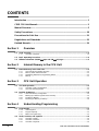
CONTENTS
Introduction ............................................................................................................... 1
CP1E CPU Unit Manuals ........................................................................................... 2
Manual Structure ....................................................................................................... 5
Safety Precautions .................................................................................................. 18
Precautions for Safe Use........................................................................................ 21
Regulations and Standards.................................................................................... 23
Related Manuals ...................................................................................................... 24
Section 1
1-1
Overview
CP1E Overview ........................................................................................................................ 1-2
1-1-1
1-2
Basic Operating Procedure .................................................................................................... 1-4
1-3
Difference between E/N/NA
-type and E/N
S(1)-type ................................................. 1-5
Section 2
2-1
Internal Memory in the CPU Unit
Internal Memory in the CPU Unit............................................................................................ 2-2
2-1-1
2-1-2
2-1-3
2-1-4
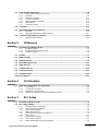
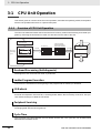
Section 3
3-1
3-2
CPU Unit Operation ................................................................................................................. 3-2
Section 4
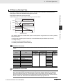
CPU Unit Memory Configuration................................................................................................. 3-5
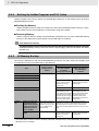
Backing Up Ladder Programs and PLC Setup............................................................................ 3-6
I/O Memory Backup .................................................................................................................... 3-6
Initializing I/O Memory at Startup................................................................................................ 3-8
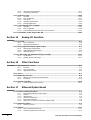
Understanding Programming
Programming ........................................................................................................................... 4-2
4-1-1
4-1-2
4-1-3
4-2
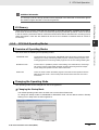
Overview of CPU Unit Operation ................................................................................................ 3-2
CPU Unit Operating Modes......................................................................................................... 3-3
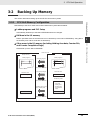
Backing Up Memory ................................................................................................................ 3-5
3-2-1
3-2-2
3-2-3
3-2-4
4-1
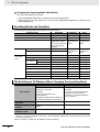
CPU Unit Memory Backup Structure .......................................................................................... 2-2
Memory Areas and Stored Data ................................................................................................. 2-3
Transferring Data from a Programming Device ........................................................................... 2-4
Backup ........................................................................................................................................ 2-4
CPU Unit Operation
3-1-1
3-1-2
User Programs ............................................................................................................................ 4-2
Program Capacity ....................................................................................................................... 4-3
Basics of Programming ............................................................................................................... 4-3
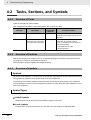
Tasks, Sections, and Symbols ............................................................................................... 4-6
4-2-1
4-2-2
4-2-3
8
Overview of Features .................................................................................................................. 1-2
Overview of Tasks ....................................................................................................................... 4-6
Overview of Sections .................................................................................................................. 4-6
Overview of Symbols .................................................................................................................. 4-6
CP1E CPU Unit Software User’s Manual(W480)
4-3
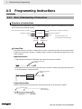
Programming Instructions...................................................................................................... 4-8
4-3-1
4-3-2
4-3-3
4-3-4
4-3-5
4-3-6
4-3-7
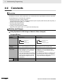
4-4
4-5
Constants ............................................................................................................................... 4-16
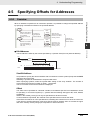
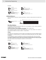
Specifying Offsets for Addresses ........................................................................................ 4-19
4-5-1
4-5-2
4-6
Overview ................................................................................................................................... 4-19
Application Examples for Address Offsets ................................................................................ 4-21
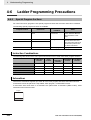
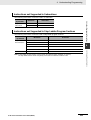
Ladder Programming Precautions...................................................................................... 4-22
4-6-1
Section 5
5-1
Basic Understanding of Instructions ........................................................................................... 4-8
Operands .................................................................................................................................... 4-9
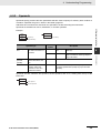
Instruction Variations................................................................................................................. 4-10
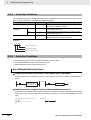
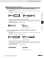
Execution Conditions ................................................................................................................ 4-10
Specifying Data in Operands .................................................................................................... 4-12
Data Formats ............................................................................................................................ 4-13
I/O Refresh Timing .................................................................................................................... 4-15
Special Program Sections......................................................................................................... 4-22
I/O Memory
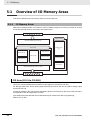
Overview of I/O Memory Areas............................................................................................... 5-2
5-1-1
5-1-2
5-1-3
I/O Memory Areas....................................................................................................................... 5-2
I/O Memory Area Address Notation ............................................................................................ 5-5
I/O Memory Areas....................................................................................................................... 5-6
5-2
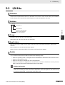
I/O Bits ...................................................................................................................................... 5-7
5-3
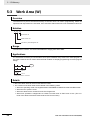
Work Area (W) .......................................................................................................................... 5-8
5-4
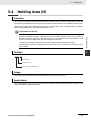
Holding Area (H) ...................................................................................................................... 5-9
5-5
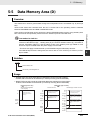
Data Memory Area (D) ........................................................................................................... 5-11
5-6
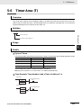
Timer Area (T) ........................................................................................................................ 5-13
5-7
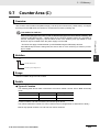
Counter Area (C) .................................................................................................................... 5-15
5-8
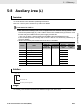
Auxiliary Area (A)................................................................................................................... 5-17
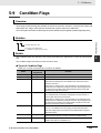
5-9
Condition Flags...................................................................................................................... 5-19
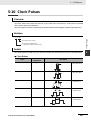
5-10 Clock Pulses .......................................................................................................................... 5-21
Section 6
6-1
I/O Allocation
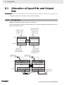
Allocation of Input Bits and Output Bits ............................................................................... 6-2
6-1-1
6-1-2
6-1-3
6-1-4
Section 7
7-1
7-2
I/O Allocation............................................................................................................................... 6-2
I/O Allocation Concepts............................................................................................................... 6-3
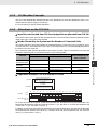
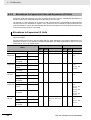
Allocations on the CPU Unit........................................................................................................ 6-3
Allocations to Expansion Units and Expansion I/O Units ............................................................ 6-4
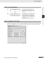
PLC Setup
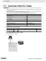
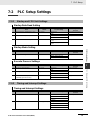
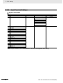
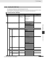
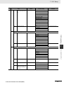
Overview of the PLC Setup..................................................................................................... 7-2
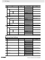
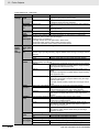
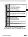
PLC Setup Settings ................................................................................................................. 7-3
7-2-1
7-2-2
7-2-3
7-2-4
7-2-5
7-2-6
7-2-7
7-2-8
7-2-9
Startup and CPU Unit Settings ................................................................................................... 7-3
Timing and Interrupt Settings ...................................................................................................... 7-3
Input Constant Settings............................................................................................................... 7-4
Built-in RS-232C Port.................................................................................................................. 7-5
Serial Option Port / Built-in RS-485 Port ..................................................................................... 7-8
Built-in Inputs ............................................................................................................................ 7-11
Pulse Output 0 Settings ............................................................................................................ 7-13
Pulse Output 1 Settings ............................................................................................................ 7-14
Built-in AD/DA: Built-in Analog I/O Settings .............................................................................. 7-16
CP1E CPU Unit Software User’s Manual(W480)
9
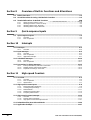
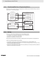
Section 8
Overview of Built-in Functions and Allocations
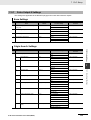
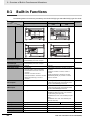
8-1
Built-in Functions .................................................................................................................... 8-2
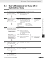
8-2
Overall Procedure for Using CP1E Built-in Functions ......................................................... 8-3
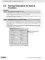
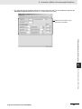
8-3
Terminal Allocations for Built-in Functions .........................................8-4
8-3-1
8-3-2
8-3-3
8-3-4
Section 9
9-1
Specifying the Functions to Use.................................................................................................. 8-4
Selecting Functions in the PLC Setup......................................................................................... 8-4
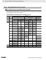
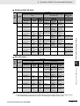
Allocating Built-in Input Terminals ............................................................................................... 8-6
Allocating Built-in Output Temrinals ............................................................................................ 8-8
Quick-response Inputs
Quick-response Inputs............................................................................................................ 9-2
9-1-1
9-1-2
Section 10
Overview ..................................................................................................................................... 9-2
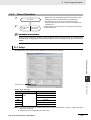
Flow of Operation........................................................................................................................ 9-3
Interrupts
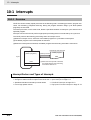
10-1 Interrupts ................................................................................................................................ 10-2
10-1-1
Overview ................................................................................................................................... 10-2
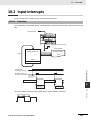
10-2 Input Interrupts ...................................................................................................................... 10-3
10-2-1
10-2-2
10-2-3
Overview ................................................................................................................................... 10-3
Flow of Operation...................................................................................................................... 10-4
Application Example.................................................................................................................. 10-7
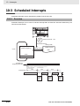
10-3 Scheduled Interrupts........................................................................................................... 10-10
10-3-1
10-3-2
Overview ................................................................................................................................. 10-10
Flow of Operation.................................................................................................................... 10-11
10-4 Precautions for Using Interrupts........................................................................................ 10-13
10-4-1
10-4-2
10-4-3
Section 11
Interrupt Task Priority and Order of Execution ........................................................................ 10-13
Related Auxiliary Area Words and Bits ................................................................................... 10-13
Duplicate Processing in each Task ......................................................................................... 10-13
High-speed Counters
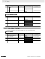
11-1 Overview................................................................................................................................. 11-2
11-1-1
11-1-2
11-1-3
Overview ................................................................................................................................... 11-2
Flow of Operation...................................................................................................................... 11-3
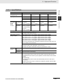
Specifications ............................................................................................................................ 11-7
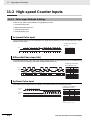
11-2 High-speed Counter Inputs................................................................................................... 11-8
11-2-1
11-2-2
11-2-3
11-2-4
11-2-5
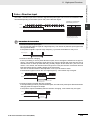
Pulse Input Methods Settings ................................................................................................... 11-8
Counting Ranges Settings ...................................................................................................... 11-10
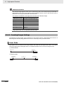
Reset Methods ........................................................................................................................ 11-11
Reading the Present Value ..................................................................................................... 11-12
Frequency Measurement ........................................................................................................ 11-13
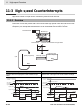
11-3 High-speed Counter Interrupts........................................................................................... 11-14
11-3-1
11-3-2
11-3-3
Overview ................................................................................................................................. 11-14
Present Value Comparison ..................................................................................................... 11-17
High-speed Counter Interrupt Instruction................................................................................ 11-21
11-4 Related Auxiliary Area Bits and Words ............................................................................. 11-26
11-5 Application Example .......................................................................................................... 11-27
10
CP1E CPU Unit Software User’s Manual(W480)
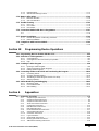
Section 12
Pulse Outputs
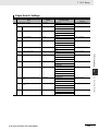
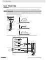
12-1 Overview................................................................................................................................. 12-2
12-1-1
12-1-2
12-1-3
Overview................................................................................................................................... 12-2
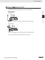
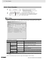
Flow of Operation ..................................................................................................................... 12-4
Specifications.......................................................................................................................... 12-12
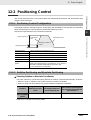
12-2 Positioning Control ............................................................................................................. 12-13
12-2-1
12-2-2
12-2-3
Positioning Control Configuration ........................................................................................... 12-13
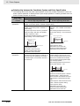
Relative Positioning and Absolute Positioning ........................................................................ 12-13
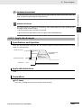
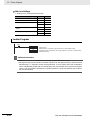
Application Example ............................................................................................................... 12-15
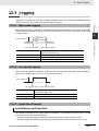
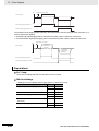
12-3 Jogging................................................................................................................................. 12-17
12-3-1
12-3-2
12-3-3
High-speed Jogging................................................................................................................ 12-17
Low-speed Jogging................................................................................................................. 12-17
Application Example ............................................................................................................... 12-17
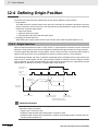
12-4 Defining Origin Position...................................................................................................... 12-20
12-4-1
12-4-2
12-4-3
12-4-4
12-4-5
12-4-6
12-4-7
Origin Searches...................................................................................................................... 12-20
Flow of Operation ................................................................................................................... 12-21
Settings in PLC Setup............................................................................................................. 12-21
Origin Search Instructions ...................................................................................................... 12-24
Origin Search Operations ....................................................................................................... 12-25
Origin Return .......................................................................................................................... 12-32
Changing the Present Value of the Pulse Output ................................................................... 12-33
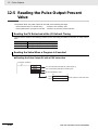
12-5 Reading the Pulse Output Present Value .......................................................................... 12-34
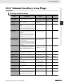
12-6 Related Auxiliary Area Flags .............................................................................................. 12-35
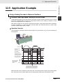
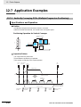
12-7 Application Examples ......................................................................................................... 12-36
12-7-1
12-7-2
Vertically Conveying PCBs (Multiple Progressive Positioning) ............................................... 12-36
Feeding Wrapping Material: Interrupt Feeding ....................................................................... 12-41
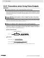
12-8 Precautions when Using Pulse Outputs ........................................................................... 12-44
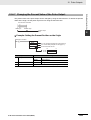
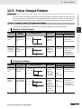
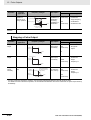
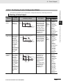
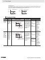
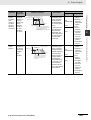
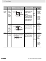
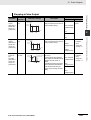
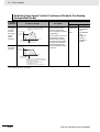
12-9 Pulse Output Pattern ........................................................................................................... 12-49
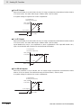
12-9-1
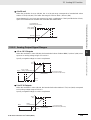
12-9-2
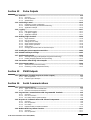
Section 13
Speed Control (Continuous Mode) ......................................................................................... 12-49
Positioning Control (Independent Mode) ................................................................................ 12-51
PWM Outputs
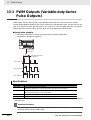
13-1 PWM Outputs (Variable-duty-factor Pulse Outputs)........................................................... 13-2
13-1-1
13-1-2
Section 14
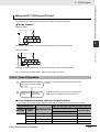
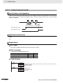
Flow of Operation ..................................................................................................................... 13-3
Ladder Program Example......................................................................................................... 13-4
Serial Communications
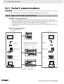
14-1 Serial Communications......................................................................................................... 14-2
14-1-1
14-1-2
Types of CPU Units and Serial Ports ........................................................................................ 14-2
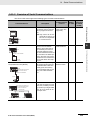
Overview of Serial Communications......................................................................................... 14-3
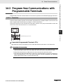
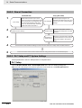
14-2 Program-free Communications with Programmable Terminals ........................................ 14-5
14-2-1
14-2-2
14-2-3
Overview................................................................................................................................... 14-5
Flow of Connection ................................................................................................................... 14-6
PLC Setup and PT System Settings......................................................................................... 14-6
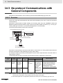
14-3 No-protocol Communications with General Components................................................. 14-8
14-3-1
14-3-2
14-3-3
14-3-4
Overview................................................................................................................................... 14-8
Flow of Operation ..................................................................................................................... 14-9
PLC Setup ................................................................................................................................ 14-9
Related Auxiliary Area Bits and Words................................................................................... 14-10
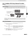
14-4 Modbus-RTU Easy Master Function .................................................................................. 14-11
14-4-1
14-4-2
Overview................................................................................................................................. 14-11
Flow of Operation ................................................................................................................... 14-11
CP1E CPU Unit Software User’s Manual(W480)
11
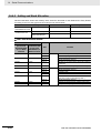
14-4-3
14-4-4
Setting and Word Allocation.................................................................................................... 14-12
Programming Examples.......................................................................................................... 14-14
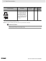
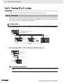
14-5 Serial PLC Links .................................................................................................................. 14-20
14-5-1
14-5-2
14-5-3
14-5-4
14-5-5
Overview ................................................................................................................................. 14-20
Flow of Operation.................................................................................................................... 14-21
PLC Setup............................................................................................................................... 14-21
Operating Specifications ......................................................................................................... 14-23
Example Application................................................................................................................ 14-28
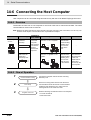
14-6 Connecting the Host Computer ......................................................................................... 14-30
14-6-1
14-6-2
14-6-3
Overview ................................................................................................................................. 14-30
Flow of Operation.................................................................................................................... 14-30
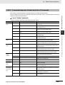
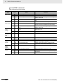
Command/response Format and List of Commands .............................................................. 14-31
14-7 Precautions on the usage of RS-485 ................................................................................. 14-33
Section 15
Analog I/O Function
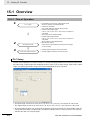
15-1 Overview................................................................................................................................. 15-2
15-1-1
15-1-2
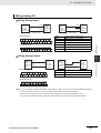
Flow of Operation...................................................................................................................... 15-2
Analog I/O Specifications .......................................................................................................... 15-6
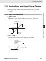
15-2 Analog Input and Output Signal Ranges............................................................................. 15-7
15-2-1
15-2-2
15-2-3
Analog Input Signal Ranges...................................................................................................... 15-7
Analog Output Signal Ranges................................................................................................... 15-9
Special functions ..................................................................................................................... 15-11
15-3 I/O Allocation and Related Auxiliary Area Flags............................................................... 15-12
15-3-1
15-3-2
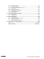
Section 16
I/O Allocation........................................................................................................................... 15-12
Related Auxiliary Area Flags................................................................................................... 15-12
Other Functions
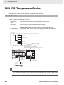
16-1 PID Temperature Control ...................................................................................................... 16-2
16-1-1
16-1-2
16-1-3
Overview ................................................................................................................................... 16-2
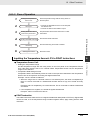
Flow of Operation...................................................................................................................... 16-3
Application Example.................................................................................................................. 16-4
16-2 Clock ....................................................................................................................................... 16-7
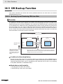
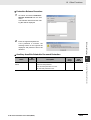
16-3 DM Backup Function ............................................................................................................. 16-8
16-3-1
16-3-2
Backing Up and Restoring DM Area Data................................................................................. 16-8
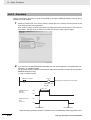
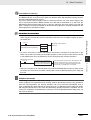
Procedure................................................................................................................................ 16-10
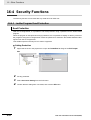
16-4 Security Functions .............................................................................................................. 16-12
16-4-1
Section 17
Ladder Program Read Protection ........................................................................................... 16-12
Ethernet Option Board
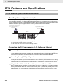
17-1 Features and Specifications ................................................................................................. 17-2
17-1-1
17-1-2
17-1-3
17-1-4
17-1-5
17-1-6
Ethernet Option Board Function Guide..................................................................................... 17-2
Features .................................................................................................................................... 17-3
Specifications ............................................................................................................................ 17-5
Software Configuration.............................................................................................................. 17-5
FINS Communications .............................................................................................................. 17-6
Differences in version of the Ethernet Option Board................................................................. 17-8
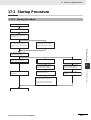
17-2 Startup Procedure ................................................................................................................. 17-9
17-2-1
Startup Procedure..................................................................................................................... 17-9
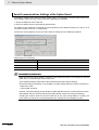
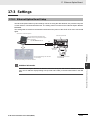
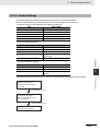
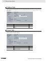
17-3 Settings ................................................................................................................................ 17-11
17-3-1
17-3-2
12
Ethernet Option Board Setup.................................................................................................. 17-11
Transferring Data from the CPU Unit ...................................................................................... 17-12
CP1E CPU Unit Software User’s Manual(W480)
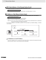
17-3-3
17-3-4
Default Settings ...................................................................................................................... 17-13
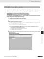
Web Browser Setting Function ............................................................................................... 17-15
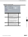
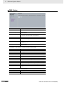
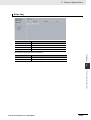
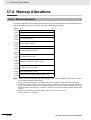
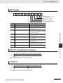
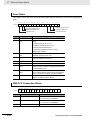
17-4 Memory Allocations ............................................................................................................ 17-26
17-4-1
17-4-2
DM Area Allocation ................................................................................................................. 17-26
CIO Area Allocation ................................................................................................................ 17-31
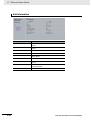
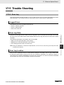
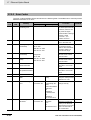
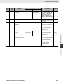
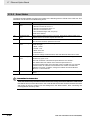
17-5 Trouble Shooting ................................................................................................................. 17-33
17-5-1
17-5-2
17-5-3
Error Log................................................................................................................................. 17-33
Error Codes ............................................................................................................................ 17-34
Error Status............................................................................................................................. 17-36
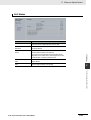
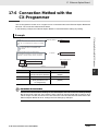
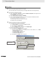
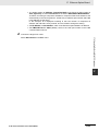
17-6 Connection Method with the CX-Programmer .................................................................. 17-37
17-6
17-6
................................................................................................................................................ 17-37
................................................................................................................................................ 17-38
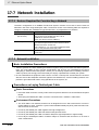
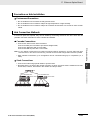
17-7 Network Installation............................................................................................................. 17-40
17-7-1
17-7-2
Devices Required for Constructing a Network ........................................................................ 17-40
Network Installation ................................................................................................................ 17-40
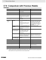
17-8 Comparison with Previous Models .................................................................................... 17-42
Note
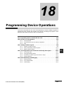
Section 18
................................................................................................................................................ 17-42
Programming Device Operations
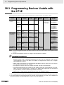
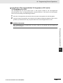
18-1 Programming Devices Usable with the CP1E ..................................................................... 18-2
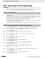
18-2 Overview of CX-Programmer................................................................................................ 18-4
18-2-1
18-2-2
18-2-3
CX-Programmer........................................................................................................................ 18-4
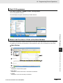
CX-Programmer Flow from Startup to Operation ..................................................................... 18-4
Help .......................................................................................................................................... 18-7
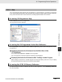
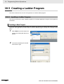
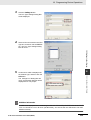
18-3 Creating a Ladder Program .................................................................................................. 18-8
18-3-1
18-3-2
18-3-3
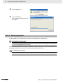
Inputting a Ladder Program ...................................................................................................... 18-8
Saving and Reading Ladder Programs................................................................................... 18-15
Editing Ladder Programs ........................................................................................................ 18-16
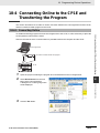
18-4 Connecting Online to the CP1E and Transferring the Program ...................................... 18-19
18-4-1
18-4-2
18-4-3
18-4-4
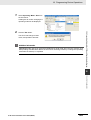
Connecting Online .................................................................................................................. 18-19
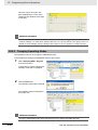
Changing Operating Modes.................................................................................................... 18-20
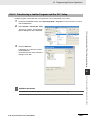
Transferring a Ladder Program and the PLC Setup................................................................ 18-21
Starting Operation .................................................................................................................. 18-22
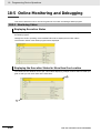
18-5 Online Monitoring and Debugging..................................................................................... 18-24
18-5-1
18-5-2
18-5-3
Section A
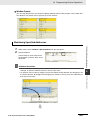
Monitoring Status.................................................................................................................... 18-24
Force-set/Reset Bits ............................................................................................................... 18-26
Online Editing ......................................................................................................................... 18-27
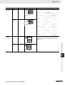
Appendices
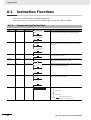
A-1 Instruction Functions..............................................................................................................A-2
A-1-1
A-1-2
A-1-3
A-1-4
A-1-5
A-1-6
A-1-7
A-1-8
A-1-9
A-1-10
A-1-11
A-1-12
A-1-13
A-1-14
Sequence Input Instructions ....................................................................................................... A-2
Sequence Output Instructions .................................................................................................... A-3
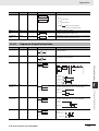
Sequence Control Instructions ................................................................................................... A-5
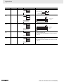
Timer and Counter Instructions .................................................................................................. A-7
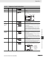
Comparison Instructions........................................................................................................... A-10
Data Movement Instructions ..................................................................................................... A-12
Data Shift Instructions .............................................................................................................. A-15
Increment/Decrement Instructions............................................................................................ A-17
Symbol Math Instructions ......................................................................................................... A-18
Conversion Instructions ............................................................................................................ A-22
Logic Instructions...................................................................................................................... A-26
Special Math Instructions ......................................................................................................... A-27
Floating-point Math Instructions ............................................................................................... A-27
Table Data Processing Instructions .......................................................................................... A-30
CP1E CPU Unit Software User’s Manual(W480)
13
A-1-15
A-1-16
A-1-17
A-1-18
A-1-19
A-1-20
A-1-21
A-1-22
A-1-23
A-1-24
Data Control Instructions ..........................................................................................................A-31
Subroutine Instructions .............................................................................................................A-35
Interrupt Control Instructions.....................................................................................................A-36
High-speed Counter/Pulse Output Instructions.........................................................................A-37
Step Instructions .......................................................................................................................A-44
Basic I/O Unit Instructions.........................................................................................................A-45
Serial Communications Instructions..........................................................................................A-49
Clock Instructions......................................................................................................................A-50
Failure Diagnosis Instructions ...................................................................................................A-51
Other Instructions......................................................................................................................A-51
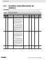
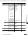
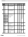
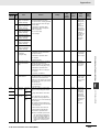
A-2 Auxiliary Area Allocations by Address................................................................................A-52
A-2-1
A-2-2
Read-only Words ......................................................................................................................A-52
Read/Write Words.....................................................................................................................A-70
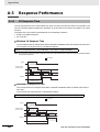
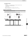
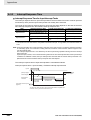
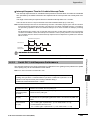
A-3 Response Performance.........................................................................................................A-80
A-3-1
A-3-2
A-3-3
A-3-4
A-3-5
I/O Response Time ...................................................................................................................A-80
Interrupt Response Time ..........................................................................................................A-82
Serial PLC Link Response Performance...................................................................................A-83
Pulse Output Start Time............................................................................................................A-84
Pulse Output Change Response Time......................................................................................A-84
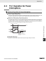
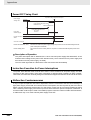
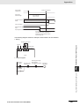
A-4 PLC Operation for Power Interruptions ...............................................................................A-85
Index ..................................................................................................................................Index-1
Revision History ................................................................................Revision-1
14
CP1E CPU Unit Software User’s Manual(W480)
Read and Understand this Manual
Please read and understand this manual before using the product. Please consult your OMRON representative
if you have any questions or comments.
Warranty and Limitations of Liability
WARRANTY
OMRON’s exclusive warranty is that the products are free from defects in materials and workmanship for a
period of one year (or other period if specified) from date of sale by OMRON.
OMRON MAKES NO WARRANTY OR REPRESENTATION, EXPRESS OR IMPLIED, REGARDING NONINFRINGEMENT, MERCHANTABILITY, OR FITNESS FOR PARTICULAR PURPOSE OF THE
PRODUCTS. ANY BUYER OR USER ACKNOWLEDGES THAT THE BUYER OR USER ALONE HAS
DETERMINED THAT THE PRODUCTS WILL SUITABLY MEET THE REQUIREMENTS OF THEIR
INTENDED USE. OMRON DISCLAIMS ALL OTHER WARRANTIES, EXPRESS OR IMPLIED.
LIMITATIONS OF LIABILITY
OMRON SHALL NOT BE RESPONSIBLE FOR SPECIAL, INDIRECT, OR CONSEQUENTIAL DAMAGES,
LOSS OF PROFITS OR COMMERCIAL LOSS IN ANY WAY CONNECTED WITH THE PRODUCTS,
WHETHER SUCH CLAIM IS BASED ON CONTRACT, WARRANTY, NEGLIGENCE, OR STRICT
LIABILITY.
In no event shall the responsibility of OMRON for any act exceed the individual price of the product on which
liability is asserted.
IN NO EVENT SHALL OMRON BE RESPONSIBLE FOR WARRANTY, REPAIR, OR OTHER CLAIMS
REGARDING THE PRODUCTS UNLESS OMRON’S ANALYSIS CONFIRMS THAT THE PRODUCTS
WERE PROPERLY HANDLED, STORED, INSTALLED, AND MAINTAINED AND NOT SUBJECT TO
CONTAMINATION, ABUSE, MISUSE, OR INAPPROPRIATE MODIFICATION OR REPAIR.
CP1E CPU Unit Software User’s Manual(W480)
15
Application Considerations
SUITABILITY FOR USE
OMRON shall not be responsible for conformity with any standards, codes, or regulations that apply to the
combination of products in the customer’s application or use of the products.
At the customer’s request, OMRON will provide applicable third party certification documents identifying
ratings and limitations of use that apply to the products. This information by itself is not sufficient for a
complete determination of the suitability of the products in combination with the end product, machine,
system, or other application or use.
The following are some examples of applications for which particular attention must be given. This is not
intended to be an exhaustive list of all possible uses of the products, nor is it intended to imply that the uses
listed may be suitable for the products:
• Outdoor use, uses involving potential chemical contamination or electrical interference, or conditions or
uses not described in this manual.
• Nuclear energy control systems, combustion systems, railroad systems, aviation systems, medical
equipment, amusement machines, vehicles, safety equipment, and installations subject to separate
industry or government regulations.
• Systems, machines, and equipment that could present a risk to life or property.
Please know and observe all prohibitions of use applicable to the products.
NEVER USE THE PRODUCTS FOR AN APPLICATION INVOLVING SERIOUS RISK TO LIFE OR
PROPERTY WITHOUT ENSURING THAT THE SYSTEM AS A WHOLE HAS BEEN DESIGNED TO
ADDRESS THE RISKS, AND THAT THE OMRON PRODUCTS ARE PROPERLY RATED AND INSTALLED
FOR THE INTENDED USE WITHIN THE OVERALL EQUIPMENT OR SYSTEM.
PROGRAMMABLE PRODUCTS
OMRON shall not be responsible for the user’s programming of a programmable product, or any
consequence thereof.
16
CP1E CPU Unit Software User’s Manual(W480)
Disclaimers
CHANGE IN SPECIFICATIONS
Product specifications and accessories may be changed at any time based on improvements and other
reasons.
It is our practice to change model numbers when published ratings or features are changed, or when
significant construction changes are made. However, some specifications of the products may be changed
without any notice. When in doubt, special model numbers may be assigned to fix or establish key
specifications for your application on your request. Please consult with your OMRON representative at any
time to confirm actual specifications of purchased products.
DIMENSIONS AND WEIGHTS
Dimensions and weights are nominal and are not to be used for manufacturing purposes, even when
tolerances are shown.
PERFORMANCE DATA
Performance data given in this manual is provided as a guide for the user in determining suitability and does
not constitute a warranty. It may represent the result of OMRON’s test conditions, and the users must
correlate it to actual application requirements. Actual performance is subject to the OMRON Warranty and
Limitations of Liability.
ERRORS AND OMISSIONS
The information in this manual has been carefully checked and is believed to be accurate; however, no
responsibility is assumed for clerical, typographical, or proofreading errors, or omissions.
CP1E CPU Unit Software User’s Manual(W480)
17
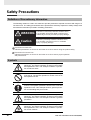
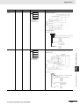
Safety Precautions
Definition of Precautionary Information
The following notation is used in this manual to provide precautions required to ensure safe usage of a
CP-series PLC. The safety precautions that are provided are extremely important to safety. Always read
and heed the information provided in all safety precautions.
WARNING
Indicates an imminently hazardous situation which,
if not avoided, will result in death or serious injury.
Additionally, there may be severe property damage.
Caution
Indicates a potentially hazardous situation which,
if not avoided, may result in minor or moderate
injury, or property damage.
Precautions for Safe Use
Indicates precautions on what to do and what not to do to ensure using the product safely.
Precautions for Correct Use
Indicates precautions on what to do and what not to do to ensure proper operation
and performance.
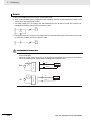
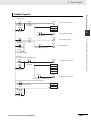
Symbols
The triangle symbol indicates precautions (including
warnings). The specific operation is shown in the triangle
and explained in text. This example indicates a precaution for electric shock.
The circle and slash symbol indicates operations that you
must not do. The specific operation is shown in the circle
and explained in text.
The filled circle symbol indicates operations that you
must do. The specific operation is shown in the circle and
explained in text. This example shows a general precaution for something that you must do.
The triangle symbol indicates precautions (including
warnings). The specific operation is shown in the triangle
and explained in text. This example indicates a general
precaution.
The triangle symbol indicates precautions (including
warnings). The specific operation is shown in the triangle
and explained in text. This example indicates a precaution for hot surfaces.
18
CP1E CPU Unit Software User’s Manual(W480)
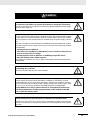
Caution
Be sure to sufficiently confirm the safety at the destination when you transfer
the program or I/O memory or perform procedures to change the I/O memory.
Devices connected to PLC outputs may incorrectly operate regardless of the operating mode of the CPU Unit.
With an E
(S)-type CPU Unit or with an N/NA
(S)-type CPU Unit without a Battery, the contents of the DM Area (D) *, Holding Area (H), the Counter Present Values
(C), the status of Counter Completion Flags (C), and the status of bits in the Auxiliary
Area (A) related to clock functions may be unstable when the power supply is turned
ON.
*This does not apply to areas backed up to EEPROM using the DM backup function.
If the DM backup function is being used, be sure to use one of the following methods
for initialization.
1. Clearing All Areas to All Zeros
Select the Clear Held Memory (HR/DM/CNT) to Zero Check Box in the Startup
Data Read Area in the PLC Setup.
2. Clearing Specific Areas to All Zeros or Initializing to Specific Values
Make the settings from a ladder program.
If the data is not initialized, the unit or device may operate unexpectedly because of
unstable data.
Execute online edit only after confirming that no adverse effects will be caused
by extending the cycle time.
Otherwise, the input signals may not be readable.
The DM Area (D), Holding Area (H), Counter Completion Flags (C), and Counter
Present Values (C) will be held by the Battery if a Battery is mounted in a CP1EN/NA
(S
)D
-
CPU Unit. When the battery voltage is low, however, I/O memory areas that are held (including the DM, Holding, and Counter Areas) will be unstable. The unit or device may operate unexpectedly because of unstable data.
Use the Battery Error Flag or other measures to stop outputs if external outputs are performed from a ladder program based on the contents of the DM
Area or other I/O memory areas.
Sufficiently check safety if I/O bit status or present values are monitored in the
Ladder Section Pane or present values are monitored in the Watch Pane.
If bits are set, reset, force-set, or force-reset by inadvertently pressing a shortcut key,
devices connected to PLC outputs may operate incorrectly regardless of the operating mode.
CP1E CPU Unit Software User’s Manual(W480)
19
Caution
Program so that the memory area of the start address is not exceeded when
using a word address or symbol for the offset.
For example, write the program so that processing is executed only when the indirect
specification does not cause the final address to exceed the memory area by using
an input comparison instruction or other instruction.
If an indirect specification causes the address to exceed the area of the start address,
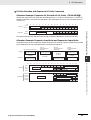
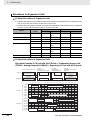
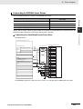
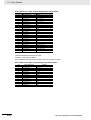
the system will access data in other area, and unexpected operation may occur.
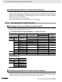
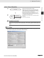
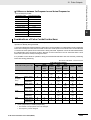
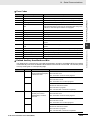
Set the temperature range according to the type of temperature sensor connected to the Unit.
Temperature data will not be converted correctly if the temperature range does not
match the sensor.
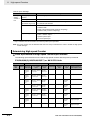
Do not set the temperature range to any values other than those for which temperature ranges are given in the following table.
An incorrect setting may cause operating errors.
20
CP1E CPU Unit Software User’s Manual(W480)
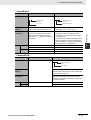
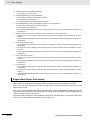
Precautions for Safe Use
Observe the following precautions when using a CP-series PLC.
z Handling
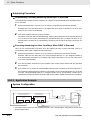
• To initialize the DM Area, back up the initial contents for the DM Area to backup memory using
one of the following methods.
• Set the number of words of the DM Area to be backed up starting with D0 in the Number of CH
of DM for backup Box in the Startup Data Read Area.
• Include programming to back up specified words in the DM Area to built-in EEPROM by turning
ON A751.15 (DM Backup Save Start Bit).
• Check the ladder program for proper execution before actually running it on the Unit. Not checking
the program may result in an unexpected operation.
• The ladder program and parameter area data in the CP1E CPU Units are backed up in the built-in
EEPROM backup memory. The BKUP indicator will light on the front of the CPU Unit when the
backup operation is in progress. Do not turn OFF the power supply to the CPU Unit when the
BKUP indicator is lit. The data will not be backed up if power is turned OFF and a memory error
will occur the next time the power supply is turned ON.
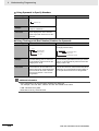
• With a CP1E CPU Unit, data memory can be backed up to the built-in EEPROM backup memory.
The BKUP indicator will light on the front of the CPU Unit when backup is in progress. Do not turn
OFF the power supply to the CPU Unit when the BKUP indicator is lit. If the power is turned OFF
during a backup, the data will not be backed up and will not be transferred to the DM Area in RAM
the next time the power supply is turned ON.
• Before replacing the battery, supply power to the CPU Unit for at least 30 minutes and then complete battery replacement within 5 minutes. Memory data may be corrupted if this precaution is
not observed.
• The equipment may operate unexpectedly if inappropriate parameters are set. Even if the appropriate parameters are set, confirm that equipment will not be adversely affected before transferring the parameters to the CPU Unit.
• Before starting operation, confirm that the contents of the DM Area is correct.
• After replacing the CPU Unit, make sure that the required data for the DM Area, Holding Area, and
other memory areas has been transferred to the new CPU Unit before restarting operation.
• Do not attempt to disassemble, repair, or modify any Units. Any attempt to do so may result in malfunction, fire, or electric shock.
• Confirm that no adverse effect will occur in the system before attempting any of the following. Not
doing so may result in an unexpected operation.
• Changing the operating mode of the PLC (including the setting of the startup operating mode).
• Force-setting/force-resetting any bit in memory.
• Changing the present value of any word or any set value in memory.
z External Circuits
• Always configure the external circuits to turn ON power to the PLC before turning ON power to the
control system. If the PLC power supply is turned ON after the control power supply, temporary
errors may result in control system signals because the output terminals on DC Output Units and
other Units will momentarily turn ON when power is turned ON to the PLC.
• Fail-safe measures must be taken by the customer to ensure safety in the event that outputs from
output terminals remain ON as a result of internal circuit failures, which can occur in relays, transistors, and other elements.
CP1E CPU Unit Software User’s Manual(W480)
21
• If the I/O Hold Bit is turned ON, the outputs from the PLC will not be turned OFF and will maintain
their previous status when the PLC is switched from RUN or MONITOR mode to PROGRAM
mode. Make sure that the external loads will not produce dangerous conditions when this occurs.
(When operation stops for a fatal error, including those produced with the FALS instruction, all outputs from PLC will be turned OFF and only the internal output status in the CPU Unit will be maintained.)
22
CP1E CPU Unit Software User’s Manual(W480)
Regulations and Standards
Trademarks
SYSMAC is a registered trademark for Programmable Controllers made by OMRON Corporation.
CX-One is a registered trademark for Programming Software made by OMRON Corporation.
Windows is a registered trademark of Microsoft Corporation.
Other system names and product names in this document are the trademarks or registered trademarks
of their respective companies.
CP1E CPU Unit Software User’s Manual(W480)
23
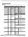
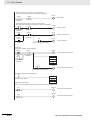
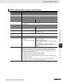
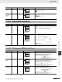
Related Manuals
The following manuals are related to the CP1E. Use them together with this manual.
Manual name
SYSMAC CP Series
CP1E CPU Unit Software User’s Manual
(this manual)
Cat. No.
W480
Model numbers
CP1E-E
SD
-
CP1E-N
S
D
-
CP1E-E
D
-
Application
To learn the software
specifications of the
CP1E PLCs
Contents
Describes the following information for CP1E
PLCs.
• CPU Unit operation
CP1E-N
D
-
• Internal memory
CP1E-NA
D
-
• Programming
• Settings
• CPU Unit built-in functions
• Interrupts
• High-speed counter inputs
• Pulse outputs
• Serial communications
• Analog I/O function
• Other functions
Use this manual together with the CP1E CPU Unit Hardware User’s
Manual (Cat. No. W479) and Instructions Reference Manual (Cat. No.
W483).
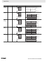
SYSMAC CP Series
CP1E CPU Unit Hardware User’s Manual
W479
CP1E-E
SD
-
CP1E-N
S
D
-
CP1E-E
D
-
To learn the hardware specifications
of the CP1E PLCs
Describes the following information for CP1E
PLCs.
• Overview and features
CP1E-N
D
-
• Basic system configuration
CP1E-NA
D
-
• Part names and functions
• Installation and settings
• Troubleshooting
Use this manual together with the CP1E CPU Unit Software User’s
Manual (Cat. No. W480) and Instructions Reference Manual (Cat. No.
W483).
SYSMAC CP Series
CP1E CPU Unit Instructions Reference Manual
W483
CP1E-E
SD
-
CP1E-N
S
D
-
CP1E-E
D
-
To learn programming instructions in
detail
Describes each programming instruction in
detail.
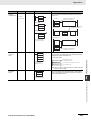
To learn communications commands for
CS/CJ/CP/NSJseries Controllers in
detail
Describes
CP1E-N
D
-
When programming, use this manual together
with the CP1E CPU Unit Software User’s Manual (Cat. No. W480).
CP1E-NA
D
-
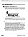
CS/CJ/CP/NSJ Series
Communications Commands Reference Manual
W342
CS1G/H-CPU
H
CS1G/H-CPU
-V1
CS1D-CPU
H
CS1D-CPU
S
CS1W-SCU
-V1
CS1W-SCB
-V1
CJ1G/H-CPU
H
CJ1G-CPU
P
CJ1M-CPU
1) C-mode commands and
2) FINS commands in detail.
Read this manual for details on C-mode and
FINS commands addressed to CPU Units.
Note This manual describes commands addressed to CPU Units. It
does not cover commands addressed to other Units or ports (e.g.,
serial communications ports on CPU Units, communications ports
on Serial Communications Units/Boards, and other Communications Units).
CJ1G-CPU
CJ1W-SCU
-V1
SYSMAC CP Series
CP1L/CP1E CPU Unit
Introduction Manual
CX-Simulator Operation
Manual
24
W461
W366
CP1L-L10D
-
CP1L-L14D
-
CP1L-L20D
-
CP1L-M30D
-
CP1L-M40D
-
CP1L-M60D
-
CP1E-E
D
-
CP1E-N
D
-
CP1E-NA
D
-
To learn the basic
setup methods of the
CP1L/CP1E PLCs
CXONE-AL
C-V4/
AL
D-V4
Operating procedures
for CX-Simulator
Simulation Support
Software for Windows
computersUsing
simulation in the
CX-Programmer with
CX-Programmer
Describes the following information for
CP1L/CP1E PLCs.
• Basic configuration and component names
• Mounting and wiring
• Programming, data transfer, and debugging
using the CX-Programmer
• Application program examples
Describes the operating procedures for the
CX-Simulator.
CP1E CPU Unit Software User’s Manual(W480)
1
1
Overview
This section gives an overview of the CP1E and describes its procedures.
1-1 CP1E Overview . . . . . . . . . . . . . . . . . . . . . . . . . . . . . . . . . . . . . . . . . . . . . . . . 1-2
1-1-1
Overview of Features . . . . . . . . . . . . . . . . . . . . . . . . . . . . . . . . . . . . . . . . . . . . 1-2
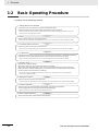
1-2 Basic Operating Procedure . . . . . . . . . . . . . . . . . . . . . . . . . . . . . . . . . . . . . . 1-4
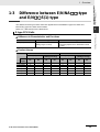
1-3 Difference between E/N/NA
-type and E/N
S-type . . . . . . . . . . . . . . . 1-5
CP1E CPU Unit Software User’s Manual(W480)
1-1
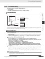
1 Overview
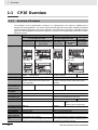
1-1
CP1E Overview
1-1-1
Overview of Features
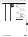
The SYSMAC CP1E Programmable Controller is a package-type PLC made by OMRON that is
designed for easy application. The CP1E includes E
(S)-type CPU Units (basic models) for standard
control operations using basic, movement, arithmetic, and comparison instructions, and N/NA
(S
)type CPU Units (application models) that supports connections to Programmable Terminals, Inverters,
and Servo Drives.
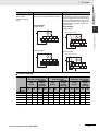
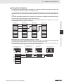
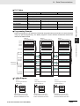
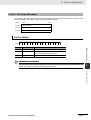
Basic Models
Appearance
CP1E Application Models
NA
-type
E
(S)-type CPU Units
N
(S
)-type CPU Units
CPU Units
CPU Unit with
CPU with 10, 14 CPU Unit with 30, 40 or CPU with 14 or
CPU Unit with
30, 40 or 60 I/O
or 20 I/O Points
60 I/O Points
20 I/O Points
20 I/O Points
Points
E
-type
E
-type
N
-type
N/NA
-type
E
S-type
I/O points
Program capacity
DM Area capacity
Mounting Expansion I/O Units and
Expansion Units
Model with transistor outputs
Pulse outputs
Built-in serial communications port
Built-in analog
Option Board
Connection port for
Programming Device
Clock
Using a Battery
Backup time of
built-in capacitor
Battery-free operation
1-2
N
S(1)-type
E
S-type
E
10/14/20/30/40
E
S
14/20/30/40/60
2K steps
2K words
Of these 1,500 words can be written to the
built-in EEPROM.
Not possible.
3 Units maximum
N
14/20/30/40/60
20
N
S(1) 30/40/60
8K steps
8K words
Of these 7,000 words can be written to the built-in
EEPROM.
Not possible.
3 Units maximum
Available (CPU Unit with 10 I/O points only)
Available
Not supported.
Not provided.
USB port
Supported (Model with transistor outputs only)
RS-232C port provided
RS-485 port provided (N
S1-type only)
Not available.
Available
Not supported.
N/NA
-type: Supported (for one
port)
N
S(1)-type: Not Supported
USB port
Not provided.
Cannot be used.
50 hours at 25°C
Provided
Can be used (sold separately).
40 hours at 25°C
Not available.
Not supported.
Always battery-free operation.
Battery-free operation if no battery is attached. Only
Only data in the built-in EEPROM will be retained data in the built-in EEPROM will be retained if power is
if power is interrupted for longer than 50 hours. interrupted for longer than 40 hours.
CP1E CPU Unit Software User’s Manual(W480)
1 Overview
For CP1E CPU Units, the following I/O memory area will be unstable after a power interruption.
• DM Area (D) (excluding words backed up to the EEPROM using the DM function)
• Holding Area (H)
• Counter Present Values and Completion Flags (C)
1-1 CP1E Overview
Precautions for Correct Use
• Auxiliary Area related to clock functions(A)
Mount the CP1W-BAT01 Battery (sold separately) to an N/NA
(S)-type CPU Unit if data in the
above areas need to be retained after a power interruption. A Battery cannot be mounted to an
E
(S)-type CPU Unit.
CP1E CPU Unit Software User’s Manual(W480)
1-3
1
1 Overview
1-2
Basic Operating Procedure
In general, use the following procedure.
1. Setting Devices and Hardware
Connect the CPU Unit, Expansion I/O Units, and Expansion Units.
Set the DIP switches on the Option Board and Expansion Units as required.
Refer to Section 3 Part Names and Functions and Section 5 Installation and Wiring in the CP1E CPU Unit
Hardware User’s Manual (Cat. No. W479).
2. Wiring
Wire the power supply, I/O, and communications.
Refer to Section 5 Installation and Wiring in the CP1E CPU Unit Hardware User’s Manual (Cat. No. W479).
3. Connecting Online to the PLC
Connect the personal computer online to the PLC.
Refer to Section 4 Programming Device in the CP1E CPU Unit Hardware User’s Manual (Cat. No. W479).
4. I/O Allocations
Allocations for built-in I/O on the CPU Unit are predetermined and memory is allocated automatically
to Expansion I/O Units and Expansion Units, so the user does not have to do anything.
Refer to Section 6 I/O Allocation in the CP1E CPU Unit Software User’s Manual (Cat. No. W480).
5. Software Setup
Make the PLC software settings.
With a CP1E CPU Unit, all you have to do is set the PLC Setup.
When using an E(S)-type CPU Unit or when using an N/NA(S)-type CPU Unit without a
Battery, be sure to consider selecting the Clear retained memory area (HR/DM/CNT) Check Box in
the Startup Data Read Area in the PLC Settings.
Refer to 3-2-4 Initializing I/O Memory at Startup, Section 7 PLC Setup in the CP1E CPU Unit Software
User’s Manual (Cat. No. W480).
6. Writing the Programs
Write the programs using the CX-Programmer.
Refer to Section 4 Programming Concepts in the CP1E CPU Unit Software User’s Manual (Cat. No. W480).
7. Checking Operation
Check the I/O wiring and the Auxiliary Area settings, and perform trial operation.
The CX-Programmer can be used for monitoring and debugging.
Refer to Section 8 Overview and Allocation of Built-in Functions.
8. Basic Program Operation
Set the operating mode to RUN mode to start operation.
1-4
CP1E CPU Unit Software User’s Manual(W480)
1 Overview
1-3 Difference between
E/N/NA
-type and E/N
S(1)-type
1-3
Difference between E/N/NA
-type
and E/N
S(1)-type
The differences among functions other than appearances of E/N/NA
-type CPU Units and
E/N
S(1)-type CPU Units are as follows.
1
Refer to A-1 Dimensions for the dimensions.
z Difference in Characteristics and Functions
Function
E
-type
Analog adjusters
E
S-type
2 adjusters
(Setting range: 0 to 255)
None
The analog adjuster PV in A642/A643 is fixed
on 0000.
z Product Lineup
Power
supply
10 I/O points
14 I/O points
20 I/O points
30 I/O points
40 I/O points
60 I/O points
E
CPU Unit
Transistor outputs
Relay outputs
(sinking/sourcing)
E
S CPU Unit
Transistor outputs
Relay Outputs
(sinking/sourcing)
AC
DC
AC
DC
AC
DC
AC
DC
{
{
{
{
{
−
{
−
−
−
−
−
{
−
−
−
−
−
{
−
−
−
−
−
−
{
{
{
{
{
−
−
−
−
−
−
−
−
−
−
−
−
−
−
−
−
−
−
CP1E CPU Unit Software User’s Manual(W480)
1-5
1-1-1 Overview of Features
E-type CPU Units
1 Overview
N-type CPU Units
z Difference in Characteristics and Functions
Function
Analog adjusters
Built-in RS-232C port
N/NA
-type
N
S(1) -type
2 adjusters
(Setting range: 0 to 255)
6 signals are supported: SD, RD, RS, CS,
DR and ER.
None
The analog adjuster PV in A642/A643 is
fixed on 0000.
4 signals are supported: SD, RD, RS and
CS.
DR (pin 7) and ER (pin 8) are not supported.
Pin
Signal
Signal
direction
Pin
Abbr.
Signal
direction
Signal
1
FG
Frame ground
−
1
FG
Frame ground
2
SD(TXD)
Send data
Outputs
2
SD(TXD)
Send data
Outputs
3
RD(RXD)
Receive data
Inputs
3
RD(RXD)
Receive data
Inputs
4
RS(RTS)
Request to send
Outputs
4
RS(RTS)
Request to send
Outputs
5
CS(CTS)
Clear to send
Inputs
5
CS(CTS)
Clear to send
Inputs
6
5V
Power
−
6
5V
Power
7
DR(DSR)
Data set ready
Inputs
7
NC
−
−
ER(DTR)
Data terminal
ready
Outputs
8
NC
−
−
9
SG(0V)
Signal ground
Signal ground
−
−
SG(0V)
FG
Frame ground
Frame ground
−
−
FG
8
9
Connector
hood
Option board
Abbr.
Connector
hood
−
−
1 port (N30/40/60, NA20 CPU Unit only)
Cannot be mounted
The following option boards can be
mounted.
There is no slot for an option board.
RS-232C Option Board
CP1W-CIF01
RS-422A/485 Option Board
CP1W-CIF11/12
Ethernet Option Board
Built-in RS-485 port
CP1W-CIF41
None
1 port (N30/40/60S1 CPU Unit only)
With 2-wire connections, it can only communicate in half duplex.
COM allocation
(Transistor outputs
only)
CIO 100.00 and CIO 100.00 correspond
with different common terminals.
NC
00
01
02
NC COM COM COM
V+
03
CIO 100.00 and CIO 100.01
are different COM.
1-6
Terminating resistance ON/OFF can be
set by DIP switch.
CIO 100.00 and CIO 100.00 correspond
with the same common terminal.
V-
00
COM(V-)
01
02
COM
03
CIO 100.00 and CIO 100.01
are the same COM.
CP1E CPU Unit Software User’s Manual(W480)
1 Overview
N/NA
-type
Not needed
Do not connect an external power supply.
Wiring Example
N
S(1) -type
Needed
It is necessary to connect a DC24V external power supply when using terminals 00
and 01 on terminal block CIO 100. Do not
connect the external power supply to the
terminals except 00 and 01 on terminal
block CIO 100.
Sinking outputs
Wiring Example
(Transistor outputs
only)
1
Sinking outputs
L
00
01
External power supply
02
NC COM COM COM
L
L
00
01
1-1-1 Overview of Features
NC
L
03
V+
V-
COM(V-)
02
COM
03
Sourcing outputs
Sourcing outputs
External power supply
NC
L
L
00
01
02
NC COM COM COM
L
L
00
01
03
V+
V-
02
COM(V+) COM
03
z Product Lineup
N
CPU Unit
RS-232C+1 option slot(*)
Transistor
outputs
Relay
(sinking/
outputs
sourcing)
Power
supply
10 I/O points
14 I/O points
20 I/O points
30 I/O points
40 I/O points
60 I/O points
AC
N
S CPU Unit
Built-in RS-232C
Transistor
outputs
Relay
(sinking/
Outputs
sourcing)
N
S1 CPU Unit
Built-in RS-232C+RS-485
Transistor
Relay
outputs
(sinking/
Outputs
sourcing)
DC
AC
DC
AC
DC
AC
DC
AC
DC
AC
DC
−
{
{
{
{
{
−
{
{
{
{
{
−
{
{
{
{
{
−
−
−
{
{
{
−
−
−
−
−
−
−
−
−
−
−
−
−
−
−
{
{
{
−
−
−
{
{
{
−
−
−
−
−
−
−
−
−
−
−
−
−
−
−
{
{
{
* Only N30/40/60 has option slot.
CP1E CPU Unit Software User’s Manual(W480)
1-3 Difference between
E/N/NA
-type and E/N
S(1)-type
Function
Power supply for transistor outputs
1-7
1 Overview
1-8
CP1E CPU Unit Software User’s Manual(W480)
2
2
Internal Memory in the CPU Unit
This section describes the types of internal memory in a CP1E CPU Unit and the data
that is stored.
2-1 Internal Memory in the CPU Unit . . . . . . . . . . . . . . . . . . . . . . . . . . . . . . . . . . 2-2
2-1-1
2-1-2
2-1-3
2-1-4
CPU Unit Memory Backup Structure . . . . . . . . . . . . . . . . . . . . . . . . . . . . . . . .
Memory Areas and Stored Data . . . . . . . . . . . . . . . . . . . . . . . . . . . . . . . . . . . .
Transferring Data from a Programming Device. . . . . . . . . . . . . . . . . . . . . . . . .
Backup . . . . . . . . . . . . . . . . . . . . . . . . . . . . . . . . . . . . . . . . . . . . . . . . . . . . . . .
CP1E CPU Unit Software User’s Manual(W480)
2-2
2-3
2-4
2-4
2-1
2 Internal Memory in the CPU Unit
2-1
Internal Memory in the CPU Unit
2-1-1
CPU Unit Memory Backup Structure
The internal memory in the CPU Unit consists of built-in RAM and built-in EEPROM. The built-in RAM is
used as execution memory and the built-in EEPROM is used as backup memory.
CPU Unit
Built-in EEPROM
Built-in RAM
Execution Memory
Backup memory
Automatic backup
User Program Area
(Backup)
Read at startup
User Program Area
Area where data is backed up
even if the power supply is
interrupted for longer than the
back-up time of the built-in
capacitor. *
Automatic backup
PLC Setup
PLC Setup
Read at startup
Area where data is cleared if
the power supply is
interrupted for longer than the
back-up time of the built-in
capacitor. *
I/O Memory Areas
Backup using bit in Auxiliary Area
DM Area
DM Area
DM Area data read at startup
* E-type CPU Units: 50 hours at 25,
N/NA-type CPU Units: 40 hours at 25
Data is retained even if the power
supply is interrupted for longer
than the backup time of the built-in
capacitor.
If a CP1W-BAT01 Battery (sold separately)
is mounted to an N/NA
(S)-type CPU
Unit, which is normally backed up by a
built-in capacitor, data will be backed up by
the battery.
Built-in RAM
The built-in RAM is the execution memory for the CPU Unit.
The user programs, PLC Setup, and I/O memory are stored in the built-in RAM.
The data is unstable when the power is interrupted.
If a CP1W-BAT01 Battery (sold separately) is mounted to an N/NA
(S)-type CPU Unit, the data is
backed up by the Battery.
The user programs and parameters are backed up to the built-in EEPROM, so they are not lost.
Built-in EEPROM
The built-in EEPROM is the backup memory for user programs, PLC Setup, and Data Memory backed
up using control bits in the Auxiliary Area.
Data is retained even if the power supply is interrupted. Only the Data Memory Area words that have
been backed up using the Auxiliary Area control bits are backed up (Refer to 16-3 DM Backup Function). All data in all other words and areas is not backed up.
2-2
CP1E CPU Unit Software User’s Manual(W480)
2 Internal Memory in the CPU Unit
2-1 Internal Memory in the CPU Unit
Caution
With an E
(S)-type CPU Unit or with an N/NA
(S)-type CPU Unit without a Battery, the contents of the DM Area (D) *, Holding Area (H), the Counter Present Values
(C), the status of Counter Completion Flags (C), and the status of bits in the Auxiliary
Area (A) related to clock functions may be unstable when the power supply is turned
ON.
*This does not apply to areas backed up to EEPROM using the DM backup function.
If the DM backup function is being used, be sure to use one of the following methods
for initialization.
2
1. Clearing All Areas to All Zeros
2-1-2 Memory Areas and Stored Data
Select the Clear retained memory area (HR/DM/CNT) to Zero Check Box in
the Startup Data Read Area in the PLC Setup.
2. Clearing Specific Areas to All Zeros or Initializing to Specific Values
Make the settings from a ladder program.
If the data is not initialized, the unit or device may operate unexpectedly because of
unstable data.
2-1-2
Memory Areas and Stored Data
The following table lists the CPU Unit memory areas and the data stored in each area.
Memory area and stored data
Details
User Program Area
User Program
The User Program Area stores the object code for executing
the user program that was created using the CX-Programmer.
Symbol Table
The symbol table contains symbols created using the CX-Programmer (symbol names, addresses, and I/O comments).
Comments
Comments are created using the CX-Programmer and include
annotations and row comments.
Program Index
The program index provides information on program sections
created using the CX-Programmer, as well as program comments.
Parameter Area
Setting PLC Setup
Built-in
RAM
Built-in
EEPROM
Stored
Stored
Stored
Stored
Stored
Not stored
Stored
Stored
Various initial settings are made in the PLC Setup using software switches.
Refer to Section 7 PLC Setup.
I/O Memory Areas
The I/O Memory Areas are used for reading and writing from
the user programs.It is partitioned into the following regions
according to purpose.
• Regions where data is cleared when power to the CPU Unit
is reset, and regions where data is retained.
• Regions where data are exchanged with other Units, and
regions that are used internally.
DM Area words backed up to backup memory (built-in
EEPROM) using control bits in the Auxiliary Area.
CP1E CPU Unit Software User’s Manual(W480)
2-3
2 Internal Memory in the CPU Unit
2-1-3
Transferring Data from a Programming Device
Data that has been created using the CX-Programmer is transferred to the internal memory in the CPU
Unit as shown in the following diagram.
CX-Programmer
User-created Programs
CPU Unit
User Program Area
User programs
User programs
Symbol Table
Symbol Table
Comments and
program index
Comments and
program index
Parameter Area
PLC Setup
PLC Setup
PLC Memory
I/O Memory Areas
CIO Area, Work Area, Holding
Area, Timer Area, Counter
Area, DM Area, and Auxiliary
Area
2-1-4
· The CX-Programmer can be
used to set status in each I/O
memory area and to write data
to the I/O memory areas.
Backup
The CPU Unit will access the backup memory in the following process.
• The program or PLC Setup are transferred from the CX-Programmer.
• The program is changed during online editing.
• DM backup is operated by the Auxiliary Area.
During these processes, BKUP LED will light, indicating that the CX-Programmer is being backed up.
There are the following limitations during backup.
• The operation mode cannot be switched from PROGRAM mode to MONITOR/RUN mode.
• If the power is interrupted when the program or PLC Setup are being backed up, memory error may
occur the next time power is turned ON.
• If the power is interrupted when the DM area is being backed up, the reading of backed up DM area
will fail the next time power is turned ON.
2-4
CP1E CPU Unit Software User’s Manual(W480)
3
CPU Unit Operation
3
This section describes the operation of the CP1E CPU Unit. Make sure that you understand the contents of this section completely before writing ladder programs.
3-1 CPU Unit Operation. . . . . . . . . . . . . . . . . . . . . . . . . . . . . . . . . . . . . . . . . . . . . 3-2
3-1-1
Overview of CPU Unit Operation . . . . . . . . . . . . . . . . . . . . . . . . . . . . . . . . . . . 3-2
3-1-2
CPU Unit Operating Modes . . . . . . . . . . . . . . . . . . . . . . . . . . . . . . . . . . . . . . . 3-3
3-2 Backing Up Memory . . . . . . . . . . . . . . . . . . . . . . . . . . . . . . . . . . . . . . . . . . . . 3-5
3-2-1
CPU Unit Memory Configuration . . . . . . . . . . . . . . . . . . . . . . . . . . . . . . . . . . . 3-5
3-2-2
3-2-3
3-2-4
Backing Up Ladder Programs and PLC Setup . . . . . . . . . . . . . . . . . . . . . . . . . 3-6
I/O Memory Backup . . . . . . . . . . . . . . . . . . . . . . . . . . . . . . . . . . . . . . . . . . . . . 3-6
Initializing I/O Memory at Startup . . . . . . . . . . . . . . . . . . . . . . . . . . . . . . . . . . . 3-8
CP1E CPU Unit Software User’s Manual(W480)
3-1
3 CPU Unit Operation
3-1
CPU Unit Operation
This section gives an overview of the CPU Unit operation, describes the operating modes, and explains
how the Unit operates when there is a power interruption.
3-1-1
Overview of CPU Unit Operation
The CPU Unit reads and writes data to the internal I/O memory areas while executing user ladder programs by executing the instructions in order one at a time from the start to the end.
CPU Unit Internal Memory
Overhead processing
(self-diagnosis)
Program execution
Access
CPU Unit
processing
cycle
I/O memory
0 0 0 0 0
0 0 0 0 0
1 1 0 1 1
0 0 1 1 1
1 0 1 0 1
0
0
0
0
0
0
0
0
1
0
0
0
0
0
1
Change in status
after all instructions
have been executed
0 1 0 1 0 1 0 0
0 1 1 0 1 0 1 0
1 1 0 0 1 0 1 0
1 0 1 1 1 0 1 1
1 0 0 0 1 1 0 1
Inputs
Exchange
Outputs
I/O refreshing
Refreshes external devices at this timing
Peripheral servicing
Overhead Processing (Self-diagnosis)
Self-diagnosis, such as an I/O bus check, is performed.
Ladder Program Execution
Instructions are executed from the beginning of the program and I/O memory is refreshed.
I/O Refresh
Data to and from external devices, such as sensors and switches, directly connected to the built-in I/O
terminals and expansion I/O terminals, is exchanged with data in the I/O memory of the PLC. This process of data exchange is called the I/O refresh.
Peripheral Servicing
Peripheral servicing is used to communicate with devices connected to the communications port or for
exchanging data with the CX-Programmer.
Cycle Time
The cycle time is the time between one I/O refresh and the next. The cycle time can be determined
beforehand for SYSMAC PLCs.
3-2
CP1E CPU Unit Software User’s Manual(W480)
3 CPU Unit Operation
Additional Information
The average cycle time during operation will be displayed in the status bar on the bottom right of
the Ladder Program Window on the CX-Programmer.
These are the PLC memory areas that are accessed by the ladder programs. SYSMAC PLCs refer to
these areas as the I/O memory. It can be accessed by specifying instruction operands. There are words
in the I/O memory area where data is cleared and words where data is retained when recovering from a
power interruption. There are also words that can be set to be cleared or retained. Refer to Section 5
I/O Memory.
3-1-2
3
CPU Unit Operating Modes
CPU Units have the following three operating modes.
PROGRAM mode:
The programs are not executed in PROGRAM mode.This mode is used for the initial
settings in PLC Setup, transferring ladder programs, checking ladder programs, and
making prepartions for executing ladder programs such as force-setting/resetting bits.
MONITOR mode:
In this mode, it is possible to perform online editing, force-set/reset bits, and change
I/O memory present values while the ladder programs are being executed. Adjustments during trial operation are also made in this mode.
RUN mode:
This is the mode in which the ladder program is executed. Some operations are disabled during this mode. It is the startup mode at initial value when the CPU Unit is
turned ON.
Changing the Operating Mode
The operating mode can be changed from the CX-Programmer.
z Changing the Startup Mode
The default operating mode when the CPU Unit is turned ON is RUN mode.
To change the startup mode to PROGRAM or MONITOR mode, set the desired mode in Startup
Setting in PLC Setup from the CX-Programmer.
3-3
3-1-2 CPU Unit Operating Modes
Overview of Operating Modes
CP1E CPU Unit Software User’s Manual(W480)
3-1 CPU Unit Operation
I/O Memory
3 CPU Unit Operation
z Changing the Operating Mode after Startup
Use one of the following procedures.
• Select PROGRAM, MONITOR, or RUN from the Startup Mode Menu.
• Right-click the PLC in the project tree, and then select PROGRAM, MONITOR, or RUN from the
Startup Mode Menu.
Operating Modes and Operation
The following table lists status and operations for each mode.
Operating mode
PROGRAM
MONITOR
RUN
Ladder program execution
Stopped
Executed
Executed
I/O refresh
Executed
Executed
Executed
External I/O status
OFF after changing to
PROGRAM mode but
can be turned ON from
the CX-Programmer
afterward.
Controlled by
the ladder programs.
Controlled by
the ladder programs.
I/O memory
Non-retained memory
Cleared
Retained memory
Retained
Controlled by
the ladder programs.
Controlled by
the ladder programs.
CX-Programmer operations
I/O memory monitoring
Yes
Yes
Yes
Ladder program monitoring
Yes
Yes
Yes
Ladder program transfer
From CPU Unit
Yes
Yes
Yes
To CPU Unit
Yes
No
No
Checking programs
Yes
No
No
Setting the PLC Setup
Yes
No
No
Changing ladder programs
Yes
Yes
No
Forced-set/reset operations
Yes
Yes
No
Changing timer/counter PV
Yes
Yes
No
Change I/O memory PV
Yes
Yes
No
The Retaining of I/O Memory When Changing the Operating Mode
Non-retained areas
Mode changes
•
•
•
•
•
Retained areas
I/O bits
Serial PLC Link Words
Work bits
Timer PV/Completion Flags
Data Registers
(Auxiliary Area bits/words are retained or
not retained depending on the address.)
• Holding Area
• DM Area
• Counter PV and Completion Flags
(Auxiliary Area bits/words are
retained or not retained depending
on the address.)
RUN or MONITOR to
PROGRAM
Cleared*
Retained
PROGRAM to RUN or
MONITOR
Cleared*
Retained
RUN to MONITOR or
MONITOR to RUN
Retained*
Retained
* The data is cleared when the IOM Hold Bit is OFF. The outputs from the Output Units will be turned OFF when a
fatal error is occurred, regardless of the status of the IOM Hold Bit, and the status of the output bits in CPU Unit’s
I/O memory is retained.
Refer to Section 5 I/O Memory for details on the I/O memory.
3-4
CP1E CPU Unit Software User’s Manual(W480)
3 CPU Unit Operation
3-2
Backing Up Memory
This section describes backing up the CP1E CPU Unit memory areas.
CPU Unit Memory Configuration
3-2 Backing Up Memory
3-2-1
Data backup to the CP1E CPU Unit’s built-in RAM memory describes as below.
z Ladder programs and PLC Setup
Automatically backed up to the built-in EEPROM whenever changed.
z DM Area in the I/O memory
Data in specified words of the DM Area can be backed up to the built-in EEPROM by using bits in
the Auxiliary Area. Other words are not backed up.
3-2-1 CPU Unit Memory Configuration
z Other areas in the I/O memory (including Holding Area data, Counter PVs,
and Counter Completion Flags)
Not backed up to the built-in EEPROM.
CP1E CPU Unit
Built-in EEPROM
backup memory
Built-in RAM
Ladder programs
Ladder programs
Changing program
PLC power turned ON
Parameter Area
PLC Setup changed
Parameter Area
PLC Setup
PLC Setup
I/O Memory Areas
PLC power turned ON
Operation using control
bits in Auxiliary Area
· I/O Area
· Work Area
· Holding Area
· Auxiliary Area
· Timer/Counter
Areas
· DM Area
Part of DM Area
PLC power turned ON
CP1E CPU Unit Software User’s Manual(W480)
3
3-5
3 CPU Unit Operation
3-2-2
Backing Up Ladder Programs and PLC Setup
Ladder programs and the PLC Setup are automatically backed up to and restored from the built-in
EEPROM backup memory.
z Backing Up Memory
Ladder programs and PLC Setup are backed up to the built-in EEPROM backup memory by transferring them from the CX-Programmer or writing them using online editing.
z Restoring Memory
Ladder programs and PLC Setup are automatically transferred from the built-in EEPROM backup
memory to the RAM memory when power is turned ON again or at startup.
Precautions for Safe Use
The BKUP indicator on the front of the CPU Unit turns ON when data is being written to the builtin EEPROM backup memory. Never turn OFF the power supply to the CPU Unit when the BKUP
indicator is lit.
3-2-3
I/O Memory Backup
I/O memory is backed up to the built-in EEPROM backup memory only when a bit in the Auxiliary Area
is turned ON to back up specified words in the DM Area.
Status at startup
Area
CIO Area
Backup to built-in
EEPROM backup
memory
Not backed up.
N/NA
(S)-type CPU
Unit with no Battery
mounted or
E
(S)-type CPU Unit
N/NA
(S)-type CPU
Unit with Battery
mounted
Cleared to all zeros.
Work Area (W)
Timer Area (T)
Holding Area (H)
Unstable when the power
supply is OFF for longer
than the I/O memory
backup time.*
The values immediately
before power interruption
are retained.
Initialized (For
N/NA
(S)-type CPU
Units, status of bits related
to clock functions is unstable when the power supply
is OFF for longer than the
I/O memory backup time.*)
Initialized (For
N/NA
(S)-type CPU
Units, status of bits related
to clock functions are
retained at their status
immediately before power
interruption.)
Counter Area (C)
Auxiliary Area (A)
DM Area
(D)
Number of words starting from D0 set in the
Number of CH of DM for
backup Box in the Startup Data Read Area in
the PLC Settings.
The specified number of
words starting from D0 is
backed up by turning ON
A751.15 (DM Backup
Save Start Bit).
The specified number of words starting from D0 is
restored from the built-in EEPROM backup memory if
the Restore D0- from backup memory Check Box is
selected in the Startup Data Read Area in the PLC Settings.
Ranges not given
above.
Not backed up.
Unstable when the power
supply is OFF for longer
than the I/O memory
backup time.
The values immediately
before power interruption
are retained.
* The values will be cleared to all zeros at startup if the Clear retained memory area (HR/DM/CNT) Check Box is
selected in the PLC Settings.
3-6
CP1E CPU Unit Software User’s Manual(W480)
3 CPU Unit Operation
I/O Memory Backup Time
The built-in capacitor’s backup time for I/O memory during a power interruption is listed below for
E
(S)-type CPU Units and N/NA
(S)-type CPU Units.
3-2 Backing Up Memory
E
(S)-type CPU Units: 50 hours at 25°C
N/NA
(S)-type CPU Units (without a battery): 40 hours at 25°C
CP1E E(S)-type CPU Unit
Backup time for I/O memory
50 hours
40 hours
CP1E N/NA(S)-type CPU
Unit without a battery
25 hours
3
20 hours
25˚C
40˚C
60˚C
Ambient temperature
The following areas are unstable when power is interrupted for longer than the I/O memory backup
times given above.
• DM Area (D) (excluding words backed up to the EEPROM using the DM backup function)
• Holding Area (H)
• Counter PVs and Completion Flags (C)
• Auxiliary Area related to clock function (A)
Additional Information
Words in the Auxiliary Area related to clock function are unstable. Others are cleared to default
values.
Power interruption time
Words
Name
Less than I/O
memory backup
time
Retained
Longer than I/O
memory backup
time
Unstable
CPU Unit
E
(S)-type
CPU Unit
A100 to A199
Error Log Area
A300
Error Log Pointer
Supported
Supported
A351 to A354
Clock Area
Not supported.
A510 to A511
Startup Time
Not supported.
A512 to A513
Power Interruption Time
Not supported.
A514
Number of Power Interruptions
Supported
A515 to A517
Operation Start Time
Not supported.
A518 to A520
Operation End Time
Not supported.
A720 to A749
Power ON Clock Data 1 to 10
Not supported.
N/NA
(S)type CPU
Unit
Supported
Precautions for Correct Use
Use an N/NA
(S)-type CPU Unit with a Battery mounted if it is necessary to retain the contents of the DM Area (D) and Holding Area (A), the Counter Present Values (C), the status of
Counter Completion Flags (C), and the status of bits in the Auxiliary Area (A) related to clock
functions when the power supply is turned ON after the power has been OFF for a period of time.
These contents and status cannot be retained with an E
(S)-type CPU Unit.
CP1E CPU Unit Software User’s Manual(W480)
3-7
3-2-3 I/O Memory Backup
9 hours
7 hours
3 CPU Unit Operation
3-2-4
Initializing I/O Memory at Startup
For E
(S)-type or N/NA
(S)-type (without a battery) CPU Units, the held areas in I/O memory
(i.e., Holding Area, Counter Present Values, Counter Completion Flags, and DM Area) may be unstable
when the power supply is turned ON. Therefore, use one of the following ways to clear these areas.
z Clearing All Held Areas to Zero at Startup
Select the Clear retained memory area (HR/DM/CNT) Check Box in the PLC Settings.
Note If the Restore D0- from backup memory Check Box is selected, only the specified words in the DM Area will
be restored from the built-in EEPROM backup memory when the power supply is turned ON.
z Initializing Specific Held Areas at Startup
Write the following type of ladder programming.
Example
P_First_Cycle
BSET
First Cycle Flag
(A200.11)
#0000
D100 to D2047 are cleared
to Zero
D100
D2047
BSET
#0000
H10 to H49 are cleared
to Zero
H10
D49
CNR
C0
C0 to C255 are cleared
to Zero
C255
3-8
CP1E CPU Unit Software User’s Manual(W480)
4
Understanding Programming
This section provides basic information on ladder programming for CP1E CPU Units.
4
4-1 Programming . . . . . . . . . . . . . . . . . . . . . . . . . . . . . . . . . . . . . . . . . . . . . . . . . . 4-2
4-1-1
User Programs . . . . . . . . . . . . . . . . . . . . . . . . . . . . . . . . . . . . . . . . . . . . . . . . . 4-2
4-1-2
Program Capacity . . . . . . . . . . . . . . . . . . . . . . . . . . . . . . . . . . . . . . . . . . . . . . . 4-3
4-1-3
Basics of Programming. . . . . . . . . . . . . . . . . . . . . . . . . . . . . . . . . . . . . . . . . . . 4-3
4-2 Tasks, Sections, and Symbols. . . . . . . . . . . . . . . . . . . . . . . . . . . . . . . . . . . . 4-6
4-2-1
Overview of Tasks. . . . . . . . . . . . . . . . . . . . . . . . . . . . . . . . . . . . . . . . . . . . . . . 4-6
4-2-2
Overview of Sections . . . . . . . . . . . . . . . . . . . . . . . . . . . . . . . . . . . . . . . . . . . . 4-6
4-2-3
Overview of Symbols . . . . . . . . . . . . . . . . . . . . . . . . . . . . . . . . . . . . . . . . . . . . 4-6
4-3 Programming Instructions . . . . . . . . . . . . . . . . . . . . . . . . . . . . . . . . . . . . . . . 4-8
4-3-1
Basic Understanding of Instructions . . . . . . . . . . . . . . . . . . . . . . . . . . . . . . . . . 4-8
4-3-2
Operands . . . . . . . . . . . . . . . . . . . . . . . . . . . . . . . . . . . . . . . . . . . . . . . . . . . . . 4-9
4-3-3
Instruction Variations . . . . . . . . . . . . . . . . . . . . . . . . . . . . . . . . . . . . . . . . . . . 4-10
4-3-4
Execution Conditions . . . . . . . . . . . . . . . . . . . . . . . . . . . . . . . . . . . . . . . . . . . 4-10
4-3-5
Specifying Data in Operands . . . . . . . . . . . . . . . . . . . . . . . . . . . . . . . . . . . . . 4-12
4-3-6
Data Formats . . . . . . . . . . . . . . . . . . . . . . . . . . . . . . . . . . . . . . . . . . . . . . . . . 4-13
4-3-7
I/O Refresh Timing . . . . . . . . . . . . . . . . . . . . . . . . . . . . . . . . . . . . . . . . . . . . . 4-15
4-4 Constants. . . . . . . . . . . . . . . . . . . . . . . . . . . . . . . . . . . . . . . . . . . . . . . . . . . . 4-16
4-5 Specifying Offsets for Addresses . . . . . . . . . . . . . . . . . . . . . . . . . . . . . . . . 4-19
4-5-1
Overview . . . . . . . . . . . . . . . . . . . . . . . . . . . . . . . . . . . . . . . . . . . . . . . . . . . . . 4-19
4-5-2
Application Examples for Address Offsets . . . . . . . . . . . . . . . . . . . . . . . . . . . 4-21
4-6 Ladder Programming Precautions . . . . . . . . . . . . . . . . . . . . . . . . . . . . . . . 4-22
4-6-1
Special Program Sections . . . . . . . . . . . . . . . . . . . . . . . . . . . . . . . . . . . . . . . 4-22
CP1E CPU Unit Software User’s Manual(W480)
4-1
4 Understanding Programming
4-1
Programming
4-1-1
User Programs
Structure of User Programs
User programs are created by using the CX-Programmer.
The user programs consist of the following parts.
• Programs
A program consists of more than one instruction and ends with an END instruction.
• Tasks (Smallest Executable Unit)
A program is assigned to an interrupt task to execute it. (In the CX-Programmer, the interrupt task
number is specified in the program properties.)
Tasks include cyclic tasks (executed with normal cyclic processing), interrupt tasks (executed when
interrupt conditions have been completed) and scheduled interrupt tasks (executed at specified intervals).
The CP1E can use only one cyclic task.
• Sections
When creating and displaying programs with the CX-Programmer, the one program can be divided
into any number of parts.
Each part is called a section.
Sections are created mainly to make programs easier to understand.
• Subroutines
You can create subroutines within a program.
User Program Data
The user programs are saved in a project file (.CXP) for the CX-Programmer along with other parameters, such as the symbol table, PLC Setup data, and I/O memory data.
Programming Languages
Programs can be written using only ladder programs.
4-2
CP1E CPU Unit Software User’s Manual(W480)
4 Understanding Programming
4-1-2
Program Capacity
The maximum program capacities of the CP1E CPU Units for all ladder programs (including symbol
table and comments) are given in the following table.
The total number of steps must not exceed the maximum program capacity.
Unit type
Model numbers
Program capacity
E
(S)-type CPU Unit
CP1E-E-
N/NA
(S)-type CPU Unit
CP1E-N/NA- 8K steps
2K steps
4-1 Programming
It is possible to check the program size by selecting Program - Memory View in the CX-Programmer.
The size of a ladder instruction depends on the specific instruction and operands that are used.
4-1-3
Basics of Programming
This section describes the basics of programming for the CP1E.
4
Basic Concepts of Ladder Programming
z Basic Points in Creating Ladder Programs
Order of Ladder Program Execution
When the ladder diagram is executed by the CPU Unit, the execution condition (i.e., power flow)
flows from left to right and top to bottom.
The flow is different from that for circuits that consist of hard-wired control relays.
For example, when the diagram in figure A is executed by the CPU Unit, power flows as though the
diodes in brackets were inserted so that output R2 is not controlled by input condition D.
The actual order of execution is indicated on the right with mnemonics.
To achieve operation without these imaginary diodes, the diagram must be rewritten. Also, the power
flow in figure B cannot be programmed directly and must be rewritten.
Figure A (Good example)
A �
C
Signal flow
(�)
� (�)
D
(�)
B
�
�
R1
�
E�
��
Order of execution (mnemonics)
�LD A
�AND B
�LD C
�OUT R1
�OUT TR0
�LD TR0
�AND D
�AND E
�OR LD
��OUT R2
R2
Figure B (Bad example)
B
A
R1
E
C
E
R2
CP1E CPU Unit Software User’s Manual(W480)
4-3
4-1-2 Program Capacity
Instructions are executed in the order that they are stored in memory (i.e., in the order of the mnemonic
code). Be sure you understand the concepts of ladder programming, and write the programs in the
proper order.
4 Understanding Programming
z Number of Times Bits Can be Used and Connection Method
• There is no limit to the number of I/O bits, work bits, timers, and other input bits that can be used.
Program structure should be kept as clear and simple as possible to make the programs easier to
understand and maintain even if it means using more input bits.
• There is no limit to the number of input conditions that can be connected in series or in parallel on
the rungs.
• Two or more OUT instructions can be connected in parallel.
0.00
0.05
TIM
0000
#100
102.00
• Output bits can also be used in input conditions.
102.00
102.00
z Ladder Programming Restrictions
• A rung error will occur if a ladder program is not connected to both bus bars.
The ladder program must be connected to both bus bars so that the execution condition will flow
from the left bus bar to the right bus bar.
If the rungs are not connected to both bus bars, a rung error will occur during the program check
on the CX-Programmer and program transfer will be impossible.
• A rung error will occur if the instruction shown below is made to directly connect to the bus bar
without an input condition.
OUT instructions, timers, counters, and other output instructions cannot be connected directly to
the left bus bar.
If one of these instructions is connected directly to the left bus bar, a rung error will occur and program transfer will be impossible.
MOV
4-4
CP1E CPU Unit Software User’s Manual(W480)
4 Understanding Programming
• A location error will occur if an instruction is not connected directly to the right bus bar.
An input condition cannot be inserted after an OUT instruction or other output instruction. The
input condition must be inserted before an OUT instruction or other output instruction. If it is
inserted after an output instruction, then a location error will occur during the program check in the
CX-Programmer.
0.00
0.01
0.03
102.01
0.04
102.01
4-1 Programming
• A warning will occur if the same output bit is used more than once in an OUT instruction.
One output bit can be used in one instruction only. Instructions in a ladder program are executed
in order from the top rung in each cycle. The result of an OUT instruction in a lower rung will be
eventually saved in the output bit. The results of any previous instructions controlling the same bit
will be overwritten and not output.
Output bit CIO 100.00
4
Output bit CIO 100.00
4-1-3 Basics of Programming
CP1E CPU Unit Software User’s Manual(W480)
4-5
4 Understanding Programming
4-2
Tasks, Sections, and Symbols
4-2-1
Overview of Tasks
There are basically two types of tasks.
Task settings must be made to use interrupt tasks with a CP1E CPU Unit.
Task type
Cyclic task
Description
Executed once per cycle
Applicable
programming
language
Ladder diagram
Execution condition
Only one for the CP1E.
(Normally, the user does not have to consider this.)
Interrupt tasks
Executed when a specific
condition occurs. The process
being executed is interrupted.
Ladder diagram
An interrupt task is placed into READY
status when the interrupt condition
occurs. A condition can be set for the following interrupt tasks.
• Scheduled interrupt tasks
• I/O interrupt tasks
4-2-2
Overview of Sections
With the CX-Programmer, programs can be created and displayed in functional units called sections.
Any program in a task can be divided into sections.
Sections improve program legibility and simplifies editing.
4-2-3
Overview of Symbols
Symbols
I/O memory area addresses or constants can be specified by using character strings registered as symbols.
The symbols are registered in the symbol table of the CX-Programmer.
Programming with symbols enables programming with names without being aware of the addresses.
The symbol table is saved in the CX-Programmer project file (.CXP) along with other parameters, such
as the user programs.
Symbol Types
There are two types of symbols that can be used in programs.
z Global Symbols
Global symbols can be accessed from all ladder programs in the PLC.
z Local Symbols
Local symbols can be accessed from only one task. They are assigned to individual tasks.
4-6
CP1E CPU Unit Software User’s Manual(W480)
4 Understanding Programming
Addresses are allocated to symbols using one of the following methods.
• User Specified allocation
• Automatic allocation using the CX-Programmer
The area of memory used for automatic allocations is set by selecting Memory Allocation - Automatic Address Allocation from the PLC Menu in the CX-Programmer.
Scope
Project tree in the
CX-Programmer
Global
symbols
PLC tree
Local
symbols
Program tree
Not
possible.
Access
from other
tasks
Access
from the
local task
Address and I/O
comment (without a symbol
name)
Possible.
Possible.
Supported
Not
possible.
Possible.
Not supported
4-2 Tasks, Sections, and Symbols
Types of symbols
Access
using symbols from a
network
4
• The same addresses is used for two different local symbols.
• The same addresses is used for a global symbol and a local symbol.
Additional Information
In programs in the CX-Programmer, global symbols and local symbols can be identified by the
following character colors and symbol icons.
Classification
Global symbols
Display color
Black (default)
Example (default color)
Start
3.00
Local symbols
Blue (default)
Error
W0.00
Select Tools - Options, and select Local Symbols or Global Symbols in Appearance to change
the color.
CP1E CPU Unit Software User’s Manual(W480)
4-7
4-2-3 Overview of Symbols
Note “Global” and “local” indicate only the applicable scope of the symbol.
They have nothing to do with the applicable scope of memory addresses.
Therefore, a warning but not an error will occur in the following cases, and it will be possible to
transfer the user program.
4 Understanding Programming
4-3
Programming Instructions
4-3-1
Basic Understanding of Instructions
Structure of Instructions
Programs consist of instructions. The conceptual structure of the inputs to and outputs from an instruction is shown in the following diagram.
Power flow (P.F., execution condition)
Instruction
Instruction condition
Flags
Power flow (P.F., execution condition)*1
Instruction condition*2
Flag
*1: Input instructions only.
*2: Not output for all instructions.
Operands
(sources)
Operands
(destinations)
I/O memory
z Power Flow
The power flow is the execution condition that is used to control the execution and instructions when
programs are executing normally. In a ladder program, power flow represents the status of the execution condition.
Input Instructions
• Load instructions indicate a logical start and outputs the execution condition.
Outputs the execution
condition.
• Intermediate instructions input the power flow as an execution condition and output the power flow
to an intermediate or output instruction.
Outputs the execution
condition.
=
D0
#1215
Output Instructions
Output instructions execute all functions, using the power flow as an execution condition.
LD power flow
Power flow for
output instruction
Input block
4-8
Output block
CP1E CPU Unit Software User’s Manual(W480)
4 Understanding Programming
4-3-2
Operands
Operands specify preset instruction parameters that are used to specify I/O memory area contents or
constants. Operands are given in boxes in the ladder programs.
Addresses and constants are entered for the operands to enable executing the instructions.
4-3 Programming Instructions
Operands are classified as source, destination, or number operands.
Example:
SBS
MOV
&0
S (source)
D0
D (destination)
Operand type
Source operand
Specifies the address of
the data to be read or a
constant.
2
N (number)
Operand
symbol
Description
S
Source operand
Source operand other than control
data (C)
C
Control data
Compound data in a source operand
that has different meanings depending on bit status.
4
Specifies the address
where data will be written.
D
−
Number
Specifies a particular
number used in the
instruction, such as a
subroutine number.
N
With numbers, it is not possible to specify an address
for indirect specification (except for jump instruction
numbers).
Operands are also called the first operand, second operand, and so on, starting from the top of the
instruction.
MOV
#0
First operand
D0
Second operand
CP1E CPU Unit Software User’s Manual(W480)
4-9
4-3-2 Operands
Destination
operand
(results)
4 Understanding Programming
4-3-3
Instruction Variations
The following variations are available for instructions to differentiate executing conditions and to refresh
data when the instruction is executed (immediate refreshing).
Variation
Symbol
Differentiation
variations
Description
−
These instructions are executed once every cycle while
the execution condition is satisfied.
ON
@
These instructions are executed only once when the execution condition turns ON.
OFF
%
These instructions are executed only once when the execution condition turns OFF.
!
Data in the built-in I/O area specified by the operands is
refreshed when the instruction is executed.
No variation used.
Immediate refreshing
Example:
!
@ MOV
Instruction (mnemonic)
Differentiation variation
Immediate refresh variation
4-3-4
Execution Conditions
The following two types of basic and special instructions can be used.
• Non-differentiated instructions: Executed every cycle
• Differentiated instructions: Executed only once
Non-differentiated Instructions
z Output Instructions (Instructions That Require Input Conditions)
These instructions are executed once every cycle while the execution condition is satisfied (ON or
OFF).
Non-differentiated
Output instructions
executed every cycle
Example:
MOV
z Input Instructions (Logical Starts and Intermediate Instructions)
These instructions read bit status, make comparisons, test bits, or perform other types of processing
every cycle. If the results are ON, the input condition is output (i.e., the execution condition is turned
ON).
Input instruction executed every cycle
4-10
Example:
CP1E CPU Unit Software User’s Manual(W480)
4 Understanding Programming
Input-differentiated Instructions
z Upwardly Differentiated Instructions (Instructions Preceded by @)
@ Upwardly
differentiated
instruction
Example:
1.02
@MOV
Executes the MOV instruction once
when CIO 1.02 turns ON.
• Input Instructions (Logical Starts and Intermediate Instructions)
The instruction reads bit status, makes comparisons, tests bits, or performs other types of processing every cycle and will output an ON execution condition (power flow) when the result
changes from OFF to ON.
The execution condition will turn OFF the next cycle.
1.03
Example:
ON execution condition created for one
cycle when CIO 1.03 turns ON.
z Downwardly Differentiated Instructions (Instruction Preceded by %)
• Output Instructions
The instruction is executed only during the cycle in which the execution condition changes from
ON to OFF.
The instruction is not executed in the following cycle.
% Downwardly
differentiated
instruction
Example:
1.02
%SET
Executes the SET instruction once
when CIO 1.02 turns OFF.
• Input Instructions (Logical Starts and Intermediate Instructions)
The instruction reads bit status, makes comparisons, tests bits, or performs other types of processing every cycle and will output an ON execution condition (power flow) when the result
changes from ON to OFF.
The execution condition will turn OFF the next cycle.
Downwardly differentiated instruction
Example:
1.03
ON execution condition created for one cycle
when CIO 1.03 turns ON.
CP1E CPU Unit Software User’s Manual(W480)
4
4-3-4 Execution Conditions
Upwardly differentiated instruction
4-3 Programming Instructions
• Output Instructions
The instruction is executed only during the cycle in which the execution condition changes from
OFF to ON.
The instruction is not executed in the following cycle.
4-11
4 Understanding Programming
4-3-5
Specifying Data in Operands
Specifying Addresses
Operand
Specifying
bit
addresses
Description
The word address and bit number are specified directly to specify a bit.
Example
Application
examples
1.02
1 . 02
Bit number 02
.
Word address CIO 1
Bit number
(00 to 15)
Word address
Specifying
word
addresses
The word address is specified directly to
specify a 16-bit word.
MOV 3 D200
3
Word address CIO 3
D200
Word address D200
Word address
Specifying
offsets for bit
addresses
In brackets, specify the number of bits to offset the specified starting bit address.
10.00[2]
.
Offset Constant
0 to 15 or word
address in I/O memory
Starting bit address
10.00[2]
Number of bits to offset the address
→Specify 10.02
Starting bit address
10.00 [W0]
Number of bits to offset the address
When W0 = &2→Specify 10.02
Starting bit address
A symbol can also be specified for the starting bit address. Only Holding, Work, and DM
Area addresses can be used regardless of
whether a physical address or symbol is
used.
A constant or word address in I/O memory
can be used for the offset. If a word address
is specified, the contents of the word is used
as the offset.
Specifying
offsets for
word
addresses
In brackets, specify the number of words to
offset the specified starting bit address.
[
]
Offset Constant of 0 or
higher or word address in
I/O memory
Starting word address
MOV 3 D0[200]
D0[2]
Number of words to offset the address
→Specify D2
Starting word address
D0 [W0]
Number of bits to offset the address
When W0 = &2→Specify D2
Starting word address
A symbol can also be specified for the starting word address. Only Holding, Work, and
DM Area addresses can be used regardless
of whether a physical address or symbol is
used.
A constant or word address in I/O memory
can be used for the offset. If a word address
is specified, the contents of the word is used
as the offset.
4-12
CP1E CPU Unit Software User’s Manual(W480)
4 Understanding Programming
Operand
Description
Specifying
indirect DM
addresses in
Binary Mode
An offset from the beginning of the DM Area
is specified. The contents of the address will
be treated as binary data (E
(S)-type
CPU Unit 0000 to 2047, N/NA
(S)-type
CPU Unit 0000 to 8191) to specify the word
address in DM Area.
Application
examples
Example
MOV #0001 @D300
@D300
Contents
&256 decimal
(#0100 hexadecimal)
Specify D00256
Add @
Specifying
indirect DM
Addresses
in BCD
Mode
An offset from the beginning of the DM Area
is specified. The contents of the address will
be treated as BCD data (E
(S)-type CPU
Unit 0000 to 2047, N/NA
(S)-type CPU
Unit 0000 to 8191) to specify the word
address in the DM Area.
Add an asterisk (*) at the front to specify an
indirect address in BCD Mode.
MOV #0001 *D200
* D200
Contents
#0100
Specify D100
4
Add *
Data Formats
The following table shows the data formats that the CP1E CPU Units can handle.
Type
Decimal
equivalent
Data format
Unsigned
binary
15
14
13
12
11
10
9
8
7
6
5
4
3
2
1
0
Binary→
215
214
213
212
211
Hexadecimal→
23
22
21
20
23
210
22
29
21
28
20
27
23
26
22
25
21
24
20
23
23
22
22
21
21
20
20
64
32
16
8
4
2
1
Decimal→ 32768 16384 8192 4096 2048 1024 512 256 128
Signed
binary
15
14
13
12
11
10
9
8
7
6
5
4
3
2
1
0
Binary: →
215
214
213
212
211
Hexadecimal: →
23
22
21
20
23
210
22
29
21
28
20
27
23
26
22
25
21
24
20
23
23
22
22
21
21
20
20
64
32
16
8
4
2
1
Decimal: → -32768 16384 8192 4096 2048 1024 512 256 128
Sign bit:
1:Negative, 0:Non-negative
4-digit
hexadecimal
&0 to
&65535
#0000 to
#FFFF
Negative:
-1 to
- 32768
Negative:
#8000 to
#FFFF
Positive:
0 to 32767
Positive:
#0000 to
#7FFF
The data is treated as 16-bit signed binary data using the leftmost bit as the
sign bit. The value is expressed in 4-digit hexadecimal.
Positive numbers: If the leftmost bit is OFF, it indicates a non-negative value.
For 4-digit hexadecimal, the value will be 0000 to 7FFF hex.
Negative numbers: If the leftmost bit is ON, it indicates a negative value. For 4digit hexadecimal, the value be 8000 to FFFF hex. It will be expressed as the
2’s complement of the absolute value of the negative value (decimal).
CP1E CPU Unit Software User’s Manual(W480)
4-13
4-3-6 Data Formats
Note For Timer Completion Flags and Counter Completion Flags, there is no distinction between word addresses and bit
addresses.
4-3-6
4-3 Programming Instructions
Add the @ symbol at the front to specify an
indirect address in Binary Mode.
4 Understanding Programming
Type
BCD (binary
coded decimal)
BCD →
15
14
13
12
11
10
9
8
7
6
5
4
3
23
22
21
20
23
22
21
20
23
22
21
20
23
Decimal →
Single-precision floatingpoint decimal
Decimal
equivalent
Data format
31
30
0 to 9
29
Sign of
mantissa
0 to 9
23
22
Exponent
21
20
2
22
0 to 9
19
1
0
21
20
4-digit
hexadecimal
#0 to #9999 #0000 to
#9999
0 to 9
2
1
0
*
−
Mantissa
Binary
sign
Exponent
Value = (-1) ×1.[Mantissa] × 2
· Sign bit (bit 31): 1: Negative, 0: Positive
· Mantissa: The 23 bits from bit 00 to bit 22 contain the mantissa, i.e., the portion
below the decimal point in 1. .....,in binary.
Indicates this value.
· The 8 bits from bit 23 to bit 30 contain the exponent. The exponent
n
n-127
is expressed in binary as the n in 2 . The actual value is 2 .
This format conforms to the IEEE 754 standard for single-precision floatingpoint data. It is used only with instructions that convert or calculate floatingpoint data.
• Input using operands in the CX-Programmer as signed decimal or 32-bit
hexadecimal with the # symbol.
• When inputting operands in the I/O Memory Edit/Monitor Window of the CXProgrammer as signed decimal values with seven digits or less, the value will
be automatically converted to scientific notation (mantissa× 10Exponent) for
setting and monitoring. Inputs must be made using scientific notation for values with eight or more digits.
Example: When -1234.00 is input, it will become -1.234000e+003 in scientific
notation. For the mantissa×10Exponent, the value before the e is the mantissa and the value after the e is the signed exponent.
* Data range for single-precision floating-point decimal: -3.402823 × 1038 ≤ Value ≤ -1.175494 × 10-38, 0, +1.175494 ×
10-38 ≤ Value ≤ 3.402823 × 1038
4-14
CP1E CPU Unit Software User’s Manual(W480)
4 Understanding Programming
4-3-7
I/O Refresh Timing
The following methods are used to refresh external I/O.
• Cyclic refreshing
• Immediate refreshing (instructions with the ! variation and IORF)
4-3 Programming Instructions
Cyclic Refreshing
I/O is all refreshed after ladder programs are executed.
Start
LD1.01
CIO 0001
OUT2.09
CIO 0002
15
0
15
0
16-bit increments
END
All actual I/O data
4
Cyclic refreshing
(batch)
Execute an instruction with the immediate refresh variation or an IORF instruction to perform I/O
refreshing while ladder programming is being executed.
Immediate Refresh
The method of specifying immediate refreshing depends on whether the object to be refreshed is builtin I/O or an Expansion Unit.
• To specify immediate refreshing for the CPU Unit’s built-in I/O, specify the immediate refresh variation
(!) of the instruction.
• To specify immediate refreshing for Expansion I/O or an Expansion Unit, use the IORF instruction.
z Instructions with Refresh Variation (!)
Add an exclamation mark (!) in front of the instruction to specify immediate refreshing.
I/O will be refreshed as shown below when an instruction is executing if a real I/O bit in the CPU
Unit’s built-in I/O is specified as an operand.
• Bit Operands: I/O refreshing for the bit will be performed.
• Word Operands: I/O refreshing for the 16 specified bits will be performed.
• Input or Source Operands: Inputs are refreshed immediately before the instruction is executed.
• Output or Destination Operands: Outputs are refreshed immediately after the instruction is executed.
z IORF(097) Instruction
An I/O refresh (IORF) instruction is supported as a special instruction to refresh actual I/O data in
the specified word range. By using this instruction, it is possible to refresh all data or data in a specified range of actual I/O in CP-series Expansion I/O and Expansion Unit during the cycle.
IORF instruction can also refresh actual I/O data in an NA-type CPU Unit at CIO 90, CIO 91 and CIO 190.
Precautions for Correct Use
It is not possible to use the immediate refresh variation (!) for the actual I/O of Expansion I/O or
an Expansion Unit. Use the IORF instruction.
CP1E CPU Unit Software User’s Manual(W480)
4-15
4-3-7 I/O Refresh Timing
I/O refresh
4 Understanding Programming
4-4
Constants
Overview
Constants are numeric values expressed in 16 or 32 bits and can be specified as instruction operands.
The following types of constants are supported.
• Bit Strings or Numeric Values (Integers)
Decimal values (with & symbol), hexadecimal values (with # symbol), BCD values (with # symbol), or
signed decimal values (with + or - symbol)
• Operands Specifying Numbers
Decimal Notation (No Symbol)
• Floating Point (Real Number) Notation
Signed decimal notation (with + or - symbol and decimal point)
Notation and Ranges
z Using Operands for Bit Strings or Numeric Values (Integers)
Unsigned Binary
Data type
Notation
Decimal values
With & symbol
With # symbol
#
& 10
4-16
Hexadecimal values
000A
Decimal value
(integer)
Hexadecimal value
using 0 to F
Decimal symbol
Hexadecimal symbol
Application
example
MOV &10 D0
MOV #000A D0
Stores 10 decimal (#000A hex) in D0.
Stores #000A hex (&10 decimal) in D0.
Precautions for
correct use
• An error will occur and the left bus bar
will be displayed in red if a hexadecimal
value including A to F is input with &
from the CX-Programmer.
• The input will be treated as an address
in the CIO Area and the contents of that
address will be specified if a decimal
value without & is input from the CXProgrammer.
• An error will occur and the left bus bar will be
displayed in red if a hexadecimal value
including A to F is input without # from the
CX-Programmer.
• The input will be treated as an address in the
CIO Area and the contents of that address
will be specified if a decimal value without #
is input from the CX-Programmer.
Range
16 bits
&0 to 65535
#0000 to #FFFF
32 bits
&0 to 4294967295
#00000000 to #FFFFFFFF
CP1E CPU Unit Software User’s Manual(W480)
4 Understanding Programming
Signed Binary
Data type
Notation
Decimal values
Hexadecimal values
Signed + or -
With # symbol
#
10
FFF6
Decimal value
(integer)
Hexadecimal value
using 0 to F
+ or - sign
Hexadecimal symbol
Application
example
MOV -10 D0
MOV # FFF6 D0
Stores 10 decimal (#FFF6 hex) in D0.
Stores #FFF6 hex (10 decimal) in D0.
Precautions for
correct use
The input will be treated as an address in
the CIO Area and the contents of that
address will be specified if a decimal
value without + or - is input from the CXProgrammer.
• An error will occur and the left bus bar will be
displayed in red if a hexadecimal value
including A to F is input without # from the
CX-Programmer.
• The input will be treated as an address in the
CIO Area and the contents of that address
will be specified if a decimal value without #
is input from the CX-Programmer.
4-4 Constants
Range
Negative: -32768 to -1
Negative: #8000 to #FFFF
4
Positive: 0 to +32767
Positive: #0000 to #7FFF
Negative: -2147483648 to -1
Negative: #80000000 to #FFFFFFFF
Positive: 0 to +2147483647
Positive: #00000000 to #7FFFFFFF
16 bits
32 bits
Unsigned BCD
Data type
Notation
Decimal values
None
BCD values
#
0010
Decimal value using
0 to 9
BCD symbol
Application
example
+B #0010 D0 D1
Precautions for
correct use
The input will be treated as an address in the CIO
Area and the contents of that address will be
specified if a decimal value without # is input from
the CX-Programmer.
Range
16 bits
Adds #0010 and the contents of D0 as BCD data
and stores the result in D1.
None
32 bits
CP1E CPU Unit Software User’s Manual(W480)
#0000 to #9999
#0000 0000 to #99999999
4 - 17
4 Understanding Programming
z Using Operands to Specify Numbers
Data type
Notation
Decimal values
No symbol (value only)
Hexadecimal values or BCD values
Not possible.
10
Number only
Application
example
SBS 0
Precautions for
correct use
An error will occur and the left bus bar
will be displayed in red if a decimal
value is input with & from the CX-Programmer.
Jumps to subroutine 0.
z Using Floating-point (Real Number) Notation for Operands
Data type
Notation
Decimal values
With + or -
Hexadecimal values
With # symbol
(for single-precision data)
+ 0.10
Decimal value
(real number)
+ or - sign
#
3DCCCCCD
Hexadecimal value
using 0 to F
Hexadecimal symbol
Application
example
FIX +0.10 D0
Converts floating point +0.10 into 16bit signed binary data and stores the
integer portion in D0.
FIX #3DCCCCCD D0
Converts floating point #3DCCCCCD (+0.10 decimal) into 16-bit signed binary data and stores the
integer portion in D0.
Precautions for
correct use
The input will be treated as an address
in the CIO Area, an error will occur,
and the left bus bar will be displayed in
red if a decimal value with a decimal
point is input without + from the CXProgrammer.
The input will be treated as an address in the CIO
Area, an error will occur, and the left bus bar will be
displayed in red if a hexadecimal value including A
to F is input without # from the CX-Programmer.
Additional Information
• Zero suppression can be used when inputting any data type.
For example, “&2” and “&02”, “#000F” and “#F” are treated as the same.
• “BIN” indicates binary data.
• BCD data is binary coded decimal.
4-18
CP1E CPU Unit Software User’s Manual(W480)
4 Understanding Programming
4-5
4-5-1
Specifying Offsets for Addresses
Overview
0.00[W0]
MOV
When the start address
is CIO 0.00 and W0 is
&2, 2 is added,
resulting in CIO 0.02.
When the start
address is D100 and
W1 is &3, 3 is added,
resulting in D103.
Examples of
Specifying Bit
Address Offsets
10.00[4]
Examples of
Specifying Word
Address Offsets
MOV
An offset of 4 is added
to the start address of
CIO 10.00, resulting in
CIO 10.04.
An offset of 12 is
added to the start
address of D100,
resulting in D112.
4
The bit address is offset by the amount specified by n (number of bits) from A (start bit address).
A [n]
Offset
Starting bit address
Number of bits to offset: +n
15 14 13 12
11 10 9
8
7
6 5
4
3
2 1
0
Word
Starting bit address A
Start Bit Address
It is possible to specify the start bit address with a bit address or with a symbol (except the NUMBER
data type cannot be used).
Offsetting is possible for all addresses except the DM Areas.
When specifying symbols, make the symbol table setting as the array variation. The number of
arrays will be the maximum number of offset + 1 bit at least.
The I/O comment for the start bit address is displayed.
Offset
The offset can be specified as a decimal constant, word address (but CIO Area addresses cannot
be specified), or a one-word symbol (i.e., symbols with the following data types: INT, UINT, WORD,
CHANNEL).
Words in the Auxiliary Area (A) can only be specified as a decimal constant.
If a word address is specified, the contents of the specified word is used as the offset.
If the offset exceeds bit 15 in the specified word, offsetting will continue from bit 00 in the next word.
If the offset is specified indirectly, make sure that the final bit address does not exceed the upper
limit of the memory area by using input comparison or other instruction.
CP1E CPU Unit Software User’s Manual(W480)
4-19
4-5-1 Overview
z Bit Addresses
Bit
4-5 Specifying Offsets for Addresses
When an address is specified for an instruction operand, it is possible to change the specified address
by specifying in brackets an offset for the specified address.
4 Understanding Programming
Examples:
a [2] 10.02
10.02
10.0 [2]
Offset (decimal value)
Offset (decimal value)
Start bit address; symbol a = 10.0
(bit symbol named a)
Start bit address
(bit address in I/O memory)
10.00 [W0] 10.02
a [b] 10.02
Offset when W0 = &2
(word address in I/O memory)
Start bit address
(bit address in I/O memory)
Offset; symbol b = &2
Start bit address; symbol a = 10.0
z Word Addresses
The word address is offset by the amount specified by n (number of offset words) from A (start word
address).
A [n]
Word
Start word address
Offset
Bit 15 14 13 12 11 10 9 8 7 6 5 4 3 2 1 0
A
+n
Start Word Address
It is possible to specify the start word address with a word address or with a symbol (except the
NUMBER data type cannot be used).
Offsetting is possible only for addresses in the Holding, Word, and DM Areas.
The I/O comment for the start bit address is displayed.
When specifying symbols, make the symbol table setting as the array variation. The number of
arrays will be the maximum number of offset + 1 word at least.
Offset
The offset can be specified as a decimal constant, word address (but CIO Area addresses cannot
be specified), or one-word symbol (i.e., symbols with the following data types: INT, UINT, WORD,
CHANNEL).
If a word address or symbol is specified, the contents of the specified word is used as the offset.
If the offset exceeds bit 15 in the specified word, offsetting will continue from bit 00 in the next word.
If the offset is specified indirectly, make sure that the final bit address does not exceed the upper
limit of the memory area by using input comparison or other instruction.
Examples:
D0[2]
D2
Offset (decimal value)
Start word address
(word address in I/O memory)
D0 [W0] D2
Offset; W0 = &2
(word address in I/O memory)
Start bit address
(bit address in I/O memory)
4-20
a [2] D2
Offset (decimal value)
Start word address;
symbol a (one-word symbol) = D0
a [b] D2
Offset;
symbol b(one-word symbol) = &2
Start word address;
symbol a (one-word symbol) = D0
CP1E CPU Unit Software User’s Manual(W480)
4 Understanding Programming
Caution
Program so that the memory area of the start address is not exceeded when using a
word address or symbol for the offset.
If an indirect specification causes the address to exceed the area of the start address,
the system will access data in other area, and unexpected operation may occur.
4-5-2
Application Examples for Address Offsets
It is possible to dynamically specify the offset by specifying a word address in I/O memory for the offset
in the brackets. The contents of the specified word address will be used as the offset.
For example, execution can be performed by increasing the address by incrementing the value in the
brackets and using only one instruction.
4-5 Specifying Offsets for Addresses
For example, write the program so that processing is executed only when the indirect
specification does not cause the final address to exceed the memory area by using
an input comparison instruction or other instruction.
4
z Ladder Program Example
The contents of corresponding words are added starting from the specified starting point, W0, to the
end of the areas and the sums are output to D200 to D299 starting from the specified offset from
D200.
For example, if W0 is 30, the corresponding words from D30 to D99 and D130 to D199 are added,
and the sums are output to D230 to D299.
Set the value of W0 to the offset word (W1) using the MOV instruction.
Use
the operand of the addition instruction to specify and execute D0[W1] +
D100[W1] = D200[W1].
Increment W1 to increase the offset.
Repeat this process
100 times.
Each process is performed with an input comparison instruction (<) as the execution condition so
that W1 does not exceed &100 to make sure that the upper limit of the indirect addressing range is
not exceeded.
Execution condition
a
Execution condition
a
<
W1
&100
MOV
W0
W1
When execution condition a (upwardly
differentiated) turns ON, the value of W0 is
set to W1.
FOR
&100
Starts FOR loop
+
D0[W1]
D100[W1]
D200[W1]
If execution condition a is ON and the
value of W1 is less than &100, the data
from the start position until D99 and
the data until D199 are added, and the
sum for each is output until D299.
++
While execution condition a is ON, W0 is
incremented.
W1
NEXT
CP1E CPU Unit Software User’s Manual(W480)
Returns to FOR
4-21
4-5-2 Application Examples for Address Offsets
In this example, two areas of consecutive data are used: D0 to D99 and D100 to D199.
4 Understanding Programming
4-6
Ladder Programming Precautions
4-6-1
Special Program Sections
For CP1E CPU Units, programs have special program sections that will control instruction conditions.
The following special program sections are available.
Instructions
Instruction
conditions
Subroutine sections
SBS, SBN, and RET instructions
Subroutine program
is executed.
The subroutine program
section between SBN and
RET instructions is executed.
IL-ILC sections
IL and ILC instructions
During IL
Step ladder sections
STEP instructions
The output bits are turned
OFF and timers are reset.
Other instructions will not be
executed and previous status will be maintained.
FOR-NEXT sections
FOR and NEXT instructions
Break in progress.
Looping
Program sections
Status
Instruction Combinations
The following table shows which of the special instructions can be used inside other program sections.
Subroutine
sections
IL-ILC
sections
MILH and
MILR-MILC
sections
Step ladder
sections
FOR-NEXT
sections
Subroutine sections
No
No
No
No
No
IL-ILC sections
Yes
No
No
No
Yes
MILH and MILR-MILC sections
Yes
No
Yes
No
Yes
Step ladder sections
No
Yes
Yes
No
No
FOR-NEXT sections
Yes
Yes
Yes
No
Yes
Subroutines
Place all the subroutines together just after all of the main program and before the END instruction.
A subroutine cannot be placed in a step ladder, block program, or FOR-NEXT section.
If instructions other than those in a subroutine are placed after a subroutine (SBN to RET), those
instructions will not be executed.
Program
Subroutines
4-22
CP1E CPU Unit Software User’s Manual(W480)
4 Understanding Programming
Instructions not Supported in Subroutines
The following instructions cannot be used in a subroutine.
Step Ladder
Instructions
Mnemonic
Instruction
STEP
STEP DEFINE
SNXT
STEP NEXT
4-6 Ladder Programming Precautions
Classification
by function
Instructions not Supported in Step Ladder Program Sections
The following instructions cannot be used in step ladder program sections.
Classification
by function
Sequence Control Instructions
Instruction
FOR, NEXT, and BREAK
FOR, NEXT, and BREAK LOOP
END
END
IL and ILC
INTERLOCK and INTERLOCK CLEAR
JMP and JME
JUMP and JUMP END
CJP
CONDITIONAL JUMP and CONDITIONAL JUMP NOT
SBN and RET
SUBROUTINE ENTRY and SUBROUTINE RETURN
4
Note A step ladder program section can be used in an interlock section (between IL and ILC).
The step ladder section will be completely reset when the interlock condition is ON.
CP1E CPU Unit Software User’s Manual(W480)
4-23
4-6-1 Special Program Sections
Subroutines
Mnemonic
4 Understanding Programming
4-24
CP1E CPU Unit Software User’s Manual(W480)
5
I/O Memory
This section describes the types of I/O memory areas in a CP1E CPU Unit and the
details.
Be sure you understand the information in the section before attempting to write ladder
diagrams.
Refer to the CP1E CPU Unit Instructions Reference Manual (Cat. No. W483) for
detailed information on programming instructions.
5-1 Overview of I/O Memory Areas . . . . . . . . . . . . . . . . . . . . . . . . . . . . . . . . . . . 5-2
5-1-1
5-1-2
I/O Memory Areas . . . . . . . . . . . . . . . . . . . . . . . . . . . . . . . . . . . . . . . . . . . . . . 5-2
I/O Memory Area Address Notation . . . . . . . . . . . . . . . . . . . . . . . . . . . . . . . . . 5-5
5-1-3
I/O Memory Areas . . . . . . . . . . . . . . . . . . . . . . . . . . . . . . . . . . . . . . . . . . . . . . 5-6
5-2 I/O Bits . . . . . . . . . . . . . . . . . . . . . . . . . . . . . . . . . . . . . . . . . . . . . . . . . . . . . . . 5-7
5-3 Work Area (W) . . . . . . . . . . . . . . . . . . . . . . . . . . . . . . . . . . . . . . . . . . . . . . . . . 5-8
5-4 Holding Area (H) . . . . . . . . . . . . . . . . . . . . . . . . . . . . . . . . . . . . . . . . . . . . . . . 5-9
5-5 Data Memory Area (D) . . . . . . . . . . . . . . . . . . . . . . . . . . . . . . . . . . . . . . . . . 5-11
5-6 Timer Area (T) . . . . . . . . . . . . . . . . . . . . . . . . . . . . . . . . . . . . . . . . . . . . . . . . 5-13
5-7 Counter Area (C) . . . . . . . . . . . . . . . . . . . . . . . . . . . . . . . . . . . . . . . . . . . . . 5-15
5-8 Auxiliary Area (A) . . . . . . . . . . . . . . . . . . . . . . . . . . . . . . . . . . . . . . . . . . . . . 5-17
5-9 Condition Flags . . . . . . . . . . . . . . . . . . . . . . . . . . . . . . . . . . . . . . . . . . . . . . 5-19
5-10 Clock Pulses . . . . . . . . . . . . . . . . . . . . . . . . . . . . . . . . . . . . . . . . . . . . . . . . . 5-21
CP1E CPU Unit Software User’s Manual(W480)
5-1
5
5 I/O Memory
5-1
Overview of I/O Memory Areas
This section describes the I/O memory areas in a CP1E CPU Unit.
5-1-1
I/O Memory Areas
Data can be read and written to I/O memory from the ladder programs. I/O memory consists of an area
for I/O with external devices, user areas, and system areas.
System Areas
Input bits (starting from CIO 0)
User Areas
Auxiliary Area
(A)
Timer Area (T)
Work Area (W)
DM Area (D)
Counter Area (C)
Holding Area (H)
Condition Flags
Clock Pulses
Output bits (starting from CIO 100)
CIO Area (CIO 0 to CIO 289)
In the CIO Area, input bit addresses range from CIO 0 to CIO 99, output bit addresses range from CIO
100 to CIO 199 and addresses for serial PLC links range from CIO 200 to CIO 289.
For NA-type CPU Units, built-in analog input terminals are CIO 90 and CIO 91, built-in analog output
terminal is CIO 190.
The bits and words in the CIO Area are allocated to built-in I/O terminals on the CP1E CPU Unit and to
the Expansion Units and Expansion I/O Units.
Input words and output bits that are not allocated may be used as work bits in programming.
Refer to 5-2 I/O Bits
5-2
CP1E CPU Unit Software User’s Manual(W480)
5 I/O Memory
User Areas
These areas can be used freely by the user.
z Work Area (W)
The Word Area is part of the internal memory of the CPU Unit. It is used in programming. Unlike the
input bits and output bits in the CIO Area, I/O to and from external devices is not refreshed for this
area.
Refer to 5-3 Work Area (W)
z Holding Area (H)
The Holding Area is part of the internal memory of the CPU Unit. It is used in programming. Unlike
the input bits and output bits in the CIO Area, I/O to and from external devices is not refreshed for
this area.
These words retain their content when the PLC is turned ON or the operating mode is switched
between PROGRAM mode and RUN or MONITOR mode.
This data is unstable if power is reset when the battery is not mounted.
5-1 Overview of I/O Memory Areas
Use this area for work words and bits before using any words in the CIO Area. These words should
be used first in programming because they will not be assigned to new functions in future versions of
CP1E CPU Units.
5
Refer to 5-4 Holding Area (H)
This data area is used for general data storage and manipulation and is accessible only by word (16
bits).
These words retain their content when the PLC is turned ON or the operating mode is switched
between PROGRAM mode and RUN or MONITOR mode.
Specified words can be retained in the built-in EEPROM backup memory using Auxiliary Area bits.
This data is unstable if power is reset when the battery is not mounted.
Refer to 5-5 Data Memory Area (D)
z Timer Area (T)
There are two parts to the Timer Area: the Timer Completion Flags and the timer Present Values
(PVs).
Up to 256 timers with timer numbers T0 to T255 can be used.
• Timer Completion Flags
Each Timer Completion Flag is accessed as one bit using the timer number.
A Completion Flag is turned ON when the set time of the timer elapses.
• Timer PVs
Each timer PV is accessed as one word (16 bits) using the timer number.
The PV increases or decreases as the timer operates.
Refer to 5-6 Timer Area (T)
CP1E CPU Unit Software User’s Manual(W480)
5-3
5-1-1 I/O Memory Areas
z Data Memory Area (D)
5 I/O Memory
z Counter Area (C)
There are two parts to the Counter Area: the Counter Completion Flags and the Counter Present
Values (PVs).
Up to 256 counters with counter numbers C0 to C255 can be used.
These words retain their content when the PLC is turned ON or the operating mode is switched
between PROGRAM mode and RUN or MONITOR mode.
This data is unstable if power is reset, when the battery is not mounted.
• Counter Completion Flags
Each Counter Completion Flag is accessed as one bit using the counter number.
A Completion Flag is turned ON when the set value of the counter is reached.
• Counter PVs
Each counter PV is accessed as one word (16 bits) using the timer number.
The PVs count up or down as the counter operates.
Refer to 5-7 Counter Area (C)
System Areas
System Areas contain bits and words with preassigned functions.
z Auxiliary Area (A)
The words and bits in this area have preassigned functions.
Refer to A-2 Auxiliary Area Allocations by Address
z Condition Flags
The Condition Flags include the flags that indicate the results of instruction execution, as well as the
Always ON and Always OFF Flags.
The Condition Flags are specified with global symbols rather than with addresses. For example: P_on
z Clock Pulses
The Clock Pulses are turned ON and OFF by the CPU Unit’s internal timer.
The Clock Pulses are specified with global symbols rather than with addresses. For example: P_0_02
5-4
CP1E CPU Unit Software User’s Manual(W480)
5 I/O Memory
5-1-2
I/O Memory Area Address Notation
An I/O memory can be addressed using word addresses or bit addresses. The word addresses and bit
addresses are given in decimal format.
z Word Addresses
Specifies a16-bit word.
1
I/O memory area
designator
Examples: D, A, W
0
0
5-1 Overview of I/O Memory Areas
W
The word number within
the area given in decimal
z Bit Addresses
A bit addresses specifies one of the 16 bits in a word.
The word number and bit number are separated with a period.
W
0
0
Word number
.
0
Period
2
5
Bit number
(00 to 15)
On the CX-Programmer, addresses in the CIO Area (including addresses for Serial PLC Links) are
given with no I/O memory area designator. “CIO” is used as the I/O memory area designator in this
manual for clarity.
0
Inputs begin from CIO 0
Outputs begin from CIO 100
.
Period
CP1E CPU Unit Software User’s Manual(W480)
0
3
Bit number
(00 to 15)
IN
CIO 0
C
1
0
3
2
5
4
7
6
9
8
11
10
5-5
5-1-2 I/O Memory Area Address Notation
I/O memory
area designator
1
5 I/O Memory
5-1-3
I/O Memory Areas
Name
No. of bits
Word addresses
Remarks
Reference
Input Bits
1,600 bits
(100 words)
CIO 0 to CIO 99
−
Output Bits
1,600 bits
(100 words)
CIO 100 to CIO 199
−
Serial PLC
Link Words
1,440 bits
(90 words)
CIO 200 to CIO 289
−
Refer to Section 14 Serial
Communications.
Work Area (W)
1,600 bits
(100 words)
W0 to W99
−
Refer to 5-3 Work Area
(W).
Holding Area (H)
800 bits (50 words)
H0 to H49
The data is unstable if
power is interrupted, when
the battery is not mounted.
Refer to 5-4 Holding Area
(H).
E
(S)-type
CPU Unit
2K words
D0 to D2047
Data in specified words of
the DM Area can be
retained in the built-in
EEPROM in the backup
memory by using a bit in
the Auxiliary Area. Applicable words: D0 to D1499
(One word can be specified at a time.)
Refer to 5-5 Data Memory
Area (D).
N/NA
(S)type CPU Unit
8K words
D0 to D8191
Data in specified words of
the DM Area can be
retained in the built-in
EEPROM in the backup
memory by using a bit in
the Auxiliary Area.Applicable words: D0 to D6999
(One word can be specified at a time.)
Present values
256
T0 to T255
−
Timer Completion Flags
256
Present values
256
C0 to C255
The data is unstable if
power is interrupted, when
the battery is not mounted.
Counter Completion Flags
256
Read only
7,168 bits
(448 words)
A0 to A447
Read-write
4,896 bits
(306 words)
A448 to A753
CIO Area
Data Memory
Area (D)
Timer Area (T)
Counter Area (C)
Auxiliary Area
(A)
5-6
Refer to 5-2 I/O Bits.
Refer to 5-6 Timer Area
(T).
Refer to 5-7 Counter Area
(C).
−
The data is unstable if
power is interrupted, when
the battery is not mounted.
Refer to A-2 Auxiliary Area
Allocations by Address.
CP1E CPU Unit Software User’s Manual(W480)
5 I/O Memory
5-2
I/O Bits
Overview
These words are allocated to built-in I/O terminals of CP1E CPU Units, built-in analog I/O terminals of
CP1E NA-type CPU Units and CP-series Expansion Units and Expansion I/O Units.
Notation
0 . 02
Bit number: 02
Word number: 0
I/O memory area designator:
None on CX-Programmer,
“CIO” in documentation
5-2 I/O Bits
Input bits: CIO 0.00 to CIO 99.15 (100 words)
5
Range
Output bits: CIO 100.00 to CIO 199.15 (100 words)
Applications
Built-in inputs can be used as basic inputs, interrupt inputs, quick-response inputs or high-speed
counters.
Built-in outputs can only be used as basic outputs.
Refer to Section 8 Overview of Built-in Functions and Allocations for details.
Details
• Bits in the CIO Area can be force-set and force-reset.
• The contents of the CIO Area will be cleared in the following cases:
• When the operating mode is changed between PROGRAM or MONITOR mode and RUN mode
• When the PLC power is reset
• When the CIO Area is cleared from the CX-Programmer
• When PLC operation is stopped due to a fatal error other than an FALS error occurs. (The contents of the CIO Area will be retained when FALS is executed.)
Additional Information
Words that are not allocated to the built-in I/O terminals of the CPU Units, built-in analog I/O terminals of CP1E NA-type CPU Units and the Expansion Units and Expansion I/O Units can only
be used in programming. It is the same as the Work Area.
CP1E CPU Unit Software User’s Manual(W480)
5-7
5 I/O Memory
5-3
Work Area (W)
Overview
The Work Area is part of the internal memory of the CPU Unit. It is used in programming. Unlike the
input bits and output bits in the CIO Area, I/O to and from external devices is not refreshed for this area.
Notation
W 20 . 02
Bit number: 02
Word number: 20
I/O memory area designator: W
Range
The Work Area contains 100 words with addresses ranging from W0 to W99.
Applications
It is sometimes necessary to use the same set of input conditions many times in the same program. In
this case a work bit can be used to store the final condition to simplify programming work and program
design.
W10.0
W10.0
NO bit
W10.0
NC bit
Storing a Condition in a Work Bit
Details
• Bits in the Work Area can be force-set and force-reset.
• The contents of the Work Area will be cleared in the following cases:
• When the operating mode is changed between PROGRAM or MONITOR mode and RUN mode
• When the PLC power is reset
• When the Work Area is cleared from the CX-Programmer
• When PLC operation is stopped due to a fatal error other than an FALS error occurs. (The contents of the Work Area will be retained when FALS is executed.)
5-8
CP1E CPU Unit Software User’s Manual(W480)
5 I/O Memory
5-4
Holding Area (H)
Overview
The Holding Area is part of the internal memory of the CPU Unit. It is used in programming. Unlike the
input bits and output bits in the CIO Area, I/O to and from external devices is not refreshed for this area.
These words retain their content when the PLC is turned ON or the operating mode is switched
between PROGRAM mode and RUN or MONITOR mode.
Precautions for Safe Use
* This does not apply to areas backed up to EEPROM using the DM backup function.
If the DM backup function is being used, be sure to refer to 3-2-4 Initializing I/O Memory at Startup for details.
5
Notation
H 20 . 02
Bit number: 02
Word number: 20
I/O memory area designator: H
Range
The Holding area contains 50 words with addresses ranging from H0 to H49.
Applications
The Holding Area is used when you want to resume operation after a power interruption using the same
status as before the power interruption.
CP1E CPU Unit Software User’s Manual(W480)
5-4 Holding Area (H)
With an E
(S)-type CPU Unit or with an N/NA
(S)-type CPU Unit without a Battery, the
contents of the DM Area (D) *, Holding Area (H), the Counter Present Values (C), the status of
Counter Completion Flags (C), and the status of bits in the Auxiliary Area (A) related to clock
functions may be unstable when the power supply is turned ON.
5-9
5 I/O Memory
Details
• Bits in the Holding Area can be force-set and force-reset.
• When a self-maintaining bit is programmed with a Holding Area bit, the self-maintaining bit will not be
cleared even when the power is reset.
• If a Holding Area bit is not used for the self-maintaining bit, the bit will be turned OFF and the selfmaintaining bit will be cleared when the power is reset.
H0.00
H0.00
• If a Holding Area bit is used but not programmed as a self-maintaining bit, the bit will be turned OFF
by execution condition A when the power is reset.
H0.00
A
Precautions for Correct Use
• When a Holding Area bit is used in a KEEP instruction, never use a normally closed condition
for the reset input.
When the power supply goes OFF or is temporarily interrupted, the input will go OFF before
the PLCs internal power supply and the Holding Area bit will be reset.
B
Bad
Input Unit
A
~
5-10
H1.00
Reset
Set
Input Unit
~
KEEP
B
A
OK
A
Set
A
KEEP
H1.00
Reset
CP1E CPU Unit Software User’s Manual(W480)
5 I/O Memory
5-5
Data Memory Area (D)
Overview
This data area is used for general data storage and manipulation and is accessible only by word (16
bits).
These words retain their contents when the PLC is turned ON or the operating mode is switched
between PROGRAM mode and RUN or MONITOR mode.
Precautions for Safe Use
With an E
(S)-type CPU Unit or with an N/NA
(S)-type CPU Unit without a Battery, the
contents of the DM Area (D) *, Holding Area (H), the Counter Present Values (C), the status of
Counter Completion Flags (C), and the status of bits in the Auxiliary Area (A) related to clock
functions may be unstable when the power supply is turned ON.
* This does not apply to areas backed up to EEPROM using the DM backup function.
If the DM backup function is being used, be sure to refer to 3-2-4 Initializing I/O Memory at Startup for details.
Notation
D 200
Word number: 200
I/O memory area designator: D
Range
• E
(S)-type CPU Units have DM Area addresses ranging from D0 to D2047.
Of these, D0 to D1499 can be backed up in backup memory (built-in EEPROM).
• N/NA
(S)-type CPU Units have DM Area addresses ranging from D0 to D8191.
Of these, D0 to D6999 can be backed up in backup memory (built-in EEPROM).
[ E
(S)-type CPU Unit ]
[ N/NA
(S)-type CPU Unit ]
· All CPU Units Regardless
of I/O Capacity
D0
to
D0
to
Words that can be
backed up to backup
memory
D1499
· N30/40/60(S) or NA20 CPU Unit
· N14/20 CPU Unit
Words that can be backed
up to backup memory
D1199
D1200
to
D1299
D0
to
D1199
DM Fixed Allocation Words
for the Modbus-RTU Easy
Master (for Built-in RS232C Port)
D1200
to
D1299
D1500
to
D1300
D1300
to
D2047
to
D6999
D1399
D1400
to
D6999
D7000
to
D8191
D7000
to
D8191
CP1E CPU Unit Software User’s Manual(W480)
Words that can be backed
up to backup memory
DM Fixed Allocation Words
for the Modbus-RTU Easy
Master (for Built-in RS-232C
Port)
DM Fixed Allocation Words
for the Modbus-RTU Easy
Master (for Serial Option
Port)
5-11
5-5 Data Memory Area (D)
Some words in the DM Area can be saved to the built-in EEPROM backup memory using Auxiliary Area
bits. These words are specifically referred to as the backed up words in the DM Area.
5
5 I/O Memory
Applications
The DM Area is for storing numeric data. It can be used for data exchange with Programmable Terminals, serial communications devices, such as Inverters, and Analog I/O Units or Temperature I/O Units.
Details
Bits in the DM Area cannot be addressed individually.
z Backing Up to the Built-in EEPROM Backup Memory
• The number of words set in the PLC Setup can be saved to the built-in EEPROM backup memory
during operation by turning ON the DM Backup Start bit (A751.15).
• Specify in the PLC Setup whether to read the data in the DM Area words to the RAM as the initial
values when the power supply is turned ON.
Refer to 16-3 DM Backup Function for how to use DM Area words and bits.
z DM Fixed Allocation Words for the Modbus-RTU Easy Master
The following DM area words are used as command and response storage areas with the ModbusRTU Easy Master function. These words are used for other applications if the Modbus-RTU Easy
Master function is not served.
Refer to 14-4 Modbus-RTU Easy Master Function for how to use the DM Area words and bits.
z Indirect Addressing of the DM Area
Indirect addressing can be used in the DM Area.
There are two modes that can be used.
Binary-mode Addressing (@D)
If a “@” symbol is input before a DM Area address, the contents of that DM Area word is treated as
a hexadecimal (binary) address and the instruction will operate on the DM Area word at that
address.
The entire DM Area can be indirectly addressed with hexadecimal values 0000 to 1FFF.
Example: @D0
0100
D256
Address actually used.
BCD-mode Addressing (*D)
If a * symbol is input before a DM Area address, the content of that DM Area word is treated as a
BCD address and the instruction will operate on the DM Area word at that address.
Only part of the DM Area (D0 to D8192) can be indirectly addressed with BCD values 0 to 8192.
Example:
*D0
0100
D100
Address actually used.
5-12
CP1E CPU Unit Software User’s Manual(W480)
5 I/O Memory
5-6
Timer Area (T)
Overview
The Timer Area contains Timer Completion Flags (1 bit each) and timer PVs (16 bits each). The Completion Flag is turned ON when a decrementing timer PV reaches 0 (counting out) or an incrementing/decrementing timer PV reaches the set value or 0.
Notation
T
002
5-6 Timer Area (T)
Time number: 002
I/O memory area designator: T
Range
Timer numbers range from T0 to T255.
5
Details
z Types of Timers
The following table shows which instructions are used to refresh timer PVs in BCD and binary mode.
Timer instruction
BCD mode
Binary mode
TIM
TIMX
TEN-MS TIMER
TIMH
TIMHX
ONE-MS TIMER
TMHH
TMHHX
ACCUMULATIVE TIMER
TTIM
TTIMX
HUNDRED-MS TIMER
Timer numbers 0 to 255 are used by all timers listed above.
Note Only timer numbers 0 to 15 can be used in 1ms TIMER (TMHH/TMHHX).
z Timer Example: Timer Number 0 and a Timer Set Value of 1 s
· BCD mode
Timer Completion Flag
T000
TIM
000
#10
· Binary mode
Timer Completion Flag
T000
TIMX
000
#A
or &10
CP1E CPU Unit Software User’s Manual(W480)
5-13
5 I/O Memory
z Timer PV Refresh Method
Timer numbers
T0 to T255
Timer PV refresh method
The timer PV is refreshed when the instruction is executed. This can cause a delay depending
on the cycle time.
• When the cycle time is longer than 100 ms, delay is generated by the TIM/TIMX instruction.
• When the cycle time is longer than 10 ms, delay is generated by the TIMH/TIMHX instruction.
• When the cycle time is longer than 1 ms, delay is generated by the TMHH/TMHHX instruction.
Precautions for Correct Use
It is not recommended to use the same timers number in two timer instructions because the timers will not operate correctly if they are operating simultaneously.
Do not use the same timer number for more than one instruction.
If two or more timer instructions use the same timer number, an error will be generated during
the program check.
z Resetting or Maintaining Timers
• Timer Completion Flags can be force-set and force-reset.
• Timer PVs cannot be force-set or force-reset, although the PVs can be refreshed indirectly by
force-setting/resetting the Completion Flag.
• There are no restrictions in the order of using timer numbers or in the number of N.C. or N.O. conditions that can be programmed.
• Timer PVs can be read as word data and used in programming.
• The following table shows when timers will be reset or maintained.
Instruction
TIM/TIMX
TIMH/TIMHX
TMHH/
TMHHX
TTIM/
TTIMX
HUNDRED-MS
TIMER
TEN-MS TIMER
ONE-MS TIMER
ACCUMULA
TIVE TIMER
When the operating mode is
changed between PROGRAM or
MONITOR mode and RUN mode*1
PV=0
When the PLC power is reset
PV=0
Flag=OFF
Flag=OFF
CNR/CNRX instructions
(timer/counter reset)*2
PV= 9999/FFFF
Jumps (JMP-JME)
Retained
Interlocks (IL-ILC) with OFF interlock conditions
Reset (PV = SV, Timer Completion Flag = OFF)
Flag=OFF
Retained
*1 If the IOM Hold Bit (A500.12) is ON, the PV and Completion Flag will be retained when a fatal error occurs
(including execution of FALS instructions) or the operating mode is changed from PROGRAM mode to
RUN or MONITOR mode or vice-versa. (The PV and Completion Flag will be cleared when power is
cycled.)
*2 Since the TIML/TIMLX instructions do not use timer numbers, they are reset under different conditions.
The PV for a TIML/TIMLX instruction is reset to the SV.
Refer to the descriptions of these instructions for details.
5-14
CP1E CPU Unit Software User’s Manual(W480)
5 I/O Memory
5-7
Counter Area (C)
Overview
The Counter Area contains Completion Flags (1 bit each) and counter PVs (16 bits each). A Completion Flag is turned ON when the counter PV reaches the set value (counting out).
Precautions for Safe Use
* This does not apply to areas backed up to EEPROM using the DM backup function.
If the DM backup function is being used, be sure to refer to 3-2-4 Initializing I/O Memory at Startup for details.
Notation
5
C 002
Counter number: 002
I/O memory area designator: C
Range
Counter numbers range from C0 to C255.
.
Details
z Types of Counters
The following table shows which instructions are used to refresh counter PVs in BCD and binary
mode.
Counter instruction
COUNTER
REVERSIBLE COUNTER
BCD mode
Binary mode
CNT
CNTX
CNTR
CNTRX
Counter numbers 0 to 255 are used by all counters given above.
The refresh method for counter PVs can be set from the CX-Programmer to either BCD or binary.
Built-in high-speed counters 0 to 5 do not use counter numbers.
CP1E CPU Unit Software User’s Manual(W480)
5-7 Counter Area (C)
With an E
(S)-type CPU Unit or with an N/NA
(S)-type CPU Unit without a Battery, the
contents of the DM Area (D) *, Holding Area (H), the Counter Present Values (C), the status of
Counter Completion Flags (C), and the status of bits in the Auxiliary Area (A) related to clock
functions may be unstable when the power supply is turned ON.
5-15
5 I/O Memory
Precautions for Correct Use
It is not recommended to use the same counter number in two counter instructions because the
counters will not operate correctly if they are counting simultaneously.
If two or more counter instructions use the same counter number, an error will be generated during the program check.
z Counter Example: Counter Number 0 with a Counter Set Value of 10
· BCD mode
Counter Completion Flag
C000
CNT
000
#10
· Binary mode
Counter Completion Flag
C000
CNTX
000
&10
or #A
z Resetting or Maintaining Counter PVs
• Counter Completion Flags can be force-set and force-reset.
• Counter PVs cannot be force-set or force-reset, although the PVs can be refreshed indirectly by
force-setting/resetting the Counter Completion Flag.
• There are no restrictions in the order of using counter numbers or in the number of N.C. or N.O.
conditions that can be programmed.
• Counter PVs can be read as word data and used in programming.
• The following table shows when counters PVs are reset or maintained.
Instruction
PV and Counter Completion Flag when counter
is reset
CNT/CNTX
CNTR/CNTRX
COUNTER
REVERSIBLE COUNTER
PV=0
Counter Completion Flag = OFF
When the operating mode is changed between Retained
PROGRAM or MONITOR mode and RUN mode
When the PLC power is reset
Retained (Unstable when the battery is not mounted)
Reset Input
Reset
CNR/CNRX instructions
Reset
Interlocks (IL-ILC) with OFF interlock conditions Retained
5-16
CP1E CPU Unit Software User’s Manual(W480)
5 I/O Memory
5-8
Auxiliary Area (A)
Overview
The words and bits in this area have preassigned functions.
Refer to A-2 Auxiliary Area Allocations by Address for details.
Precautions for Safe Use
• Words in the Auxiliary Area related to clock function are unstable.
Power interruption time
Bit/word
Name
Within I/O
memory
backup time
Retained
Longer than
I/O memory
backup time
Unstable
CPU Unit
E
(S)type CPU
Unit
A100 to A199
Error Log Area
Supported
A300
Error Log Pointer
Supported
A351 to A354
Calendar/Clock Area
Not provided.
A510 to A511
Startup Time
Not provided.
A512 to A513
Power Interruption Time
Not provided.
A514
Number of Power Interruptions
Supported
A515 to A517
Operation Start Time
Not provided.
A518 to A520
Operation End Time
Not provided.
A720 to A749
Power ON Clock Data 1 to 10
Not provided.
N/NA
(S)type CPU
Unit
Supported
Notation
A
20.
02
Bit number: 02
Word number: 20
I/O memory area designator: A
Range
The Auxiliary Area contains 754 words with addresses ranging from A0 to A753.
CP1E CPU Unit Software User’s Manual(W480)
5-17
5-8 Auxiliary Area (A)
• With an E
(S)-type CPU Unit or with an N/NA
(S)-type CPU Unit without a Battery, the
contents of the DM Area (D) *, Holding Area (H), the Counter Present Values (C), the status of
Counter Completion Flags (C), and the status of bits in the Auxiliary Area (A) related to clock
functions may be unstable when the power supply is turned ON.
* This does not apply to areas backed up to EEPROM using the DM backup function.
If the DM backup function is being used, be sure to refer to 3-2-4 Initializing I/O Memory at
Startup for details.
5
5 I/O Memory
Applications
Applications of the bits and words in the Auxiliary Area are predefined. Ladder programs can be simplified and controllability can be improved by effectively using the bits and words in this area.
Details
• Some words or bits are set automatically by the system and others are set and manipulated by the
user.
The Auxiliary Area includes error flags set by self-diagnosis, initial settings, control bits, and status
data.
• Words and bits in this area can be read and written from the program or the CX-Programmer.
• The Auxiliary Area contains words that are read-only (A0 to A447) and words that can be read and
written (A448 to A753).
• Even the read/write bits in the Auxiliary Area cannot be force-set and force-reset continuously.
z Auxiliary Area Words and Bits in the CX-Programmer’s System-defined
Symbols
The following table gives the Auxiliary Area bits and words pre-registered in the CX-Programmer’s
global symbol table as system-defined symbols.
Refer to A-2 Auxiliary Area Allocations by Address for details.
Word/Bit
5-18
Name
Name in CX-Programmer
A200.11
First Cycle Flag
P_First_Cycle
A200.12
Step Flag
P_Step
A200.15
First Cycle Task Flag
P_First_Cycle_Task
A262
Maximum Cycle Time
P_Max_Cycle_Time
A264
Present Cycle Time
P_Cycle_Time_Value
A401.08
Cycle Time Too Long Flag
P_Cycle_Time_Error
A402.04
Battery Error Flag
P_Low_Battery
A500.15
Output OFF Bit
P_Output_Off_Bit
CP1E CPU Unit Software User’s Manual(W480)
5 I/O Memory
5-9
Condition Flags
Overview
These flags include the flags that indicate the results of instruction execution, as well as the Always ON
and Always OFF Flags. These bits are specified with symbols rather than addresses.
The CX-Programmer treats condition flags as system-defined symbols (global symbols) beginning with P_.
Notation
5-9 Condition Flags
P_ ER
Condition flag name: ER
I/O memory area designator:
P_ (indicates a system symbol name)
Details
The Condition Flags are read-only; they cannot be written from instructions or from the CX-Programmer.
The Condition Flags cannot be force-set and force-reset.
z Types of Condition Flags
Refer to 4-6 Ladder Programming Precautions for details.
Name
Always ON Flag
Name in CXProgrammer
Function
P_On
Always ON.
Always OFF Flag
P_Off
Always OFF.
Error Flag
P_ER
Turned ON when the operand data in an instruction is incorrect (an
instruction processing error) to indicate that an instruction ended
because of an error.
When the PLC Setup is set to stop operation for an instruction error
(Instruction Error Operation), program execution will be stopped and
the Instruction Processing Error Flag (A295.08) will be turned ON
when the Error Flag is turned ON.
Access Error Flag
P_AER
Turned ON when an Illegal Access Error occurs. The Illegal Access
Error indicates that an instruction attempted to access an area of
memory that should not be accessed.
When the PLC Setup is set to stop operation for an instruction error
(Instruction Error Operation), program execution will be stopped and
the Instruction Processing Error Flag (A4295.10) will be turned ON
when the Access Error Flag is turned ON.
Carry Flag
P_CY
Turned ON when there is a carry in the result of an arithmetic operation or a 1 is shifted to the Carry Flag by a Data Shift instruction.
The Carry Flag is part of the result of some Data Shift and Symbol
Math instructions.
Greater Than Flag
P_GT
Turned ON when the first operand of a Comparison Instruction is
greater than the second or a value exceeds a specified range.
Equals Flag
P_EQ
Turned ON when the two operands of a Comparison Instruction are
equal or the result of a calculation is 0.
CP1E CPU Unit Software User’s Manual(W480)
5-19
5
5 I/O Memory
Name in CXProgrammer
Name
Function
Less Than Flag
P_LT
Turned ON when the first operand of a Comparison Instruction is less
than the second or a value is below a specified range.
Negative Flag
P_N
Turned ON when the most significant bit of a result is ON.
Overflow Flag
P_OF
Turned ON when the result of calculation overflows the capacity of the
result word(s).
Underflow Flag
P_UF
Turned ON when the result of calculation underflows the capacity of
the result word(s).
Greater Than or
Equals Flag
P_GE
Turned ON when the first operand of a Comparison Instruction is
greater than or equal to the second.
Not Equal Flag
P_NE
Turned ON when the two operands of a Comparison Instruction are
not equal.
Less than or Equals
Flag
P_LE
Turned ON when the first operand of a Comparison Instruction is less
than or equal to the second.
z Using the Condition Flags
The Condition Flags are shared by all of the instructions. Their status may change after each
instruction execution in a single cycle.
Therefore, be sure to use Condition Flags on a branched output with the same execution condition
immediately after an instruction to reflect the results of instruction execution.
Example: Using Instruction A Execution Results
Instruction A
Instruction
Operand
LD
The result from instruction A
is reflected in the Equals Flag
Condition Flag
Example: =
Instruction A
AND
=
Instruction B
Instruction B
Precautions for Correct Use
The Condition Flags are shared by all of the instructions. This means that program operation can
be changed from its expected course by interruption of a single task. Be sure to consider the
effects of interrupts when writing ladder programs to prevent unexpected operation.
5-20
CP1E CPU Unit Software User’s Manual(W480)
5 I/O Memory
5-10 Clock Pulses
Overview
The Clock Pulses are turned ON and OFF by the CPU Unit’s internal timer. These bits are specified
with symbols rather than addresses.
The CX-Programmer treats condition flags as system-defined symbols (global symbols) beginning with P_.
Notation
P_ 0_02s
5-10 Clock Pulses
Clock pulse name: 0_02s
I/O memory area designator:
P_ (indicates a system symbol name)
Details
The Clock Pulses are read-only; they cannot be written from instructions or from the CX-Programmer.
z Clock Pulses
Name
0.02-s Clock Pulse
Name in CXProgrammer
Description
P_0_02s
0.01s
ON for 0.01 s
OFF for 0.01 s
0.01s
0.1-s clock pulse
P_0_1s
0.05s
ON for 0.05 s
OFF for 0.05 s
0.05s
0.2-s clock pulse
P_0_2s
0.1s
ON for 0.1 s
OFF for 0.1 s
0.1s
1-s clock pulse
P_1s
0.5s
ON for 0.5 s
OFF for 0.5 s
30s
ON for 30 s
OFF for 30 s
0.5s
1-min clock pulse
P_1min
30s
CP1E CPU Unit Software User’s Manual(W480)
5-21
5
5 I/O Memory
z Using the Clock Pulses
The following example turns a bit ON and OFF at 0.5-s intervals.
P_1s
5-22
100.00
Instruction
LD
OUT
Operand
P_1s
100.00
100.00
0.5s
0.5s
CP1E CPU Unit Software User’s Manual(W480)
6
I/O Allocation
This section describes I/O allocation used to exchange data between the CP1E CPU
Unit and other units.
Be sure you understand the information in the section before attempting to write ladder
diagrams.
6-1 Allocation of Input Bits and Output Bits . . . . . . . . . . . . . . . . . . . . . . . . . . . 6-2
6-1-1
I/O Allocation . . . . . . . . . . . . . . . . . . . . . . . . . . . . . . . . . . . . . . . . . . . . . . . . . . 6-2
6-1-2
I/O Allocation Concepts . . . . . . . . . . . . . . . . . . . . . . . . . . . . . . . . . . . . . . . . . . 6-3
6-1-3
Allocations on the CPU Unit . . . . . . . . . . . . . . . . . . . . . . . . . . . . . . . . . . . . . . 6-3
6-1-4
Allocations to Expansion Units and Expansion I/O Units . . . . . . . . . . . . . . . . . 6-4
CP1E CPU Unit Software User’s Manual(W480)
6-1
6
6 I/O Allocation
6-1
Allocation of Input Bits and Output
Bits
This section describes the allocation of input bits and output bits.
6-1-1
I/O Allocation
OMRON calls allocating I/O bits in memory “I/O allocation.”
The I/O on Expansion I/O Units are allocated I/O bits in the words following the allocated words to the
built-in I/O on the CPU Units.
Allocated 12 bits
Allocated 12 bits
in the next word
00 to 11
00 to 11
Inputs
Outputs
0CH (CIO 0)
1CH (CIO 1)
CPU Unit
Expansion I/O Unit
100CH (CIO 100)
101CH (CIO 101)
00 to 07
00 to 07
Allocated 8 bits
Allocated 8 bits in
the next word
Bit 03 in CIO 0
Bit 05 in CIO 1
0CH (CIO 0)
Inputs
C
1
0
3
2
5
4
7
1CH (CIO 1)
9
6
8
11
10
C
1
0
CPU Unit
0
Outputs
C
1
C
100CH (CIO 100)
6-2
5
4
7
6
9
8
11
10
Expansion I/O Unit
2
C
3
2
4
3
5
c
7
6
0
C
1
C
2
C
4
3
5
c
7
6
Bit 02 in CIO 101
Bit 03 in CIO 100 101CH
(CIO 101)
CP1E CPU Unit Software User’s Manual(W480)
6 I/O Allocation
6-1-2
I/O Allocation Concepts
The CPU Unit automatically allocates I/O bits to the Expansion I/O Units and Expansion Units, if connected when the power supply is turned ON.
It is not necessary to specify I/O bits allocation.
6-1-3
Allocations on the CPU Unit
The first word from which input bits are allocated is CIO 0. The first word from which output bits are allocated is CIO 100. These cannot be changed.
z Words Allocated by the System and the Number of Connected Units
The starting words for inputs and outputs are predetermined for a CP1E CPU Unit. Input bits in CIO 0,
or CIO 0 and CIO 1, and output bits in CIO 100, or CIO 100 and CIO 101, are automatically allocated to
the built-in I/O on the CPU Unit.
The words from which bits are allocated by the system and the number of Expansion I/O Units and
Expansion Units that can be connected are given in the following table.
Allocated words
CPU Unit
Input Bits
Number of Expansion
Units and Expansion I/O
Units connected
Output Bits
CIO 0
CIO 100
0 Unit
E30/40 or N30/40
CPU Unit
CIO 0 and CIO 1
CIO 100 and CIO 101
3 Units
N60 CPU Unit
CIO 0, CIO 1 and CIO 2
CIO 100, CIO 101 and CIO 102
3 Units
NA20 CPU Unit
CIO 0, CIO 90 and CIO 91 CIO 100 and CIO 190
6
6-1-2 I/O Allocation Concepts
E10/14/20 or
N14/20 CPU Unit
3 Units
z Application Example: CPU Unit with 40 I/O Points
CPU Unit with 40 I/O Points
CIO 0 (CIO 0.00 to CIO 0.11)
CIO 1 (CIO 1.00 to CIO 1.11)
Input Bits
24 inputs
16 outputs
Output Bits
15
Input Bits
CIO 0
CIO 100 (CIO 100.00 to CIO 100.07)
CIO 101 (CIO 101.00 to CIO 101.07)
14
13
12
11
Cannot be used
10
09
08
07
06
05
04
03
02
01
00
Input bits: 24
CIO 1
Output Bits
CIO 100
Cannot be used
Output bits: 16
CIO 101
For a CPU Unit with 40 I/O points, a total of 24 input bits are allocated to the input terminal block. The
bits that are allocated are input bits CIO 0.00 to CIO 0.11 (i.e., bits 00 to 11 in CIO 0) and input bits CIO
1.00 to CIO 1.11 (i.e., bits 00 to 11 in CIO 1).
In addition, a total of 16 output bits are allocated to the output terminal block. The bits that are allocated
are output bits CIO 100.00 to CIO 100.07 (i.e., bits 00 to 07 in CIO 0) and output bits CIO 101.00 to CIO
101.07 (i.e., bits 00 to 07 in CIO 1).
CP1E CPU Unit Software User’s Manual(W480)
6-1 Allocation of Input Bits and Output Bits
z Input bits are allocated from CIO 0 and output bits are allocated from CIO 100
6-3
6 I/O Allocation
6-1-4
Allocations to Expansion Units and Expansion I/O Units
Expansion Units and Expansion I/O Units connected to the CPU Unit are automatically allocated input
bits and output bits in words following those allocated to the CPU Unit.
For example, if a CPU Unit with 40 I/O points is used, CIO 0 and CIO 1 are allocated for inputs and CIO
100 and CIO 101 are allocated for outputs. Thus, words from CIO 2 onward for inputs and words from
CIO 102 onward for outputs are automatically allocated to the Expansion I/O Units and Expansion Units
in the order that the Units are connected.
Allocations to Expansion I/O Units
There are Expansion I/O Units for expanding inputs, for expanding outputs, and for expanding both
input and outputs.
I/O bits starting from bit 00 in the next word after the word allocated to the previous Expansion Unit,
Expansion I/O Unit, or CPU Unit are automatically allocated. This word is indicated as “CIO m” for input
words and as “CIO n” for output words.
Input bits
Model
No. of
bits
No. of
words
Output bits
Addresses
No. of
bits
No. of
words
CIO m, bits 00 to 07
−
None
Addresses
8-point Input Unit
CP1W-8ED
8
1
8-point
Relay outputs
Output Unit Sinking transistor
outputs
CP1W-8ER
−
None
None
8
1
CIO n, bits 00
to 07
−
None
None
16
2
CIO n, bits 00
to 07
CP1W-8ET
Sourcing transistor outputs
CP1W-8ET1
16-point
Relay outputs
Output Unit Sinking transistor
outputs
CP1W-16ER
20-point
I/O Units
Sourcing transistor outputs
CP1W-16ET1
Relay outputs
CP1W-20EDR1
Sinking transistor
outputs
CP1W-20EDT
Sourcing transistor outputs
CP1W-20EDT1
32-point
Relay outputs
Output Unit Sinking transistor
outputs
40-point
I/O Unit
6-4
CP1W-16ET
CP1W-32ER
None
CIO n+1, bits
00 to 07
12
1
−
None
CIO m, bits 00 to 11
8
1
CIO n, bits 00
to 07
None
32
4
CIO n, bits 00
to 07
CP1W-32ET
CIO n+1, bits
00 to 07
Sourcing transistor outputs
CP1W-32ET1
Relay outputs
CP1W-40EDR
Sinking transistor
outputs
CP1W-40EDT
Sourcing transistor outputs
CP1W-40EDT1
CIO n+2, bits
00 to 07
CIO n+3, bits
00 to 07
24
2
CIO m, bits 00 to 11
CIO m+1, bits 00 to
11
16
2
CIO n, bits 00
to 07
CIO n+1, bits
00 to 07
CP1E CPU Unit Software User’s Manual(W480)
6 I/O Allocation
z I/O Bits Allocation with Expansion I/O Units Connected
Allocation Example: Expansion I/O Unit with 40 I/O Points (CP1W-40ED
)
Twenty-four input bits in two words are allocated (bits 00 to 11 in CIO m and bits 00 to 11 CIO m+1).
Sixteen output bits in two words are allocated in two words (bits 00 to 07 in CIO n and bits 00 to 07
in CIO n+1).
Input bits
bit
CIO m
CIO m+1
14
13
12
11
10
09
08
07
06
05
04
03
02
01
00
Cannot be used
CIO n
Cannot be used
CIO n+1
Two input words (24 bits) and two output words (16 bits) are allocated to a 40-point I/O Unit.
Allocation Example: Expansion Input Units and Expansion Output Units
If Expansion Input Units or Expansion Output Units are connected, the input or output word not used
by an Expansion I/O Unit is allocated to the next Unit that requires it.
1st Unit:
8-point Expansion
Input Unit
CPU Unit with 30 I/O Points
Input bits
CIO 0.00 to CIO 0.11
CIO 1.00 to CIO 1.05
8 inputs
CIO 1
CIO 2
8 outputs
No outputs
CIO 102.00 to CIO 102.07
CIO 103.00 to CIO 103.07
14
13
12
11
10
09
08
07
06
05
CIO 104.00 to CIO 104.07
04
03
01
00
CPU Unit with 30 I/O Points
Cannot be used
8-point Expansion Input Unit
20-point Expansion I/O Unit
CIO 3
CIO 100
CPU Unit with
30 I/O Points
CIO 101
Output bits
02
6
6-1-4 Allocations to Expansion Units and Expansion I/O Units
15
12 inputs
16 outputs
CIO 100.00 to CIO 100.07
CIO 101.00 to CIO 101.03
CIO 0
Input bits
CIO 3.00 to CIO 3.11
No inputs
18 inputs
bit
3rd Unit:
20-point Expansion
I/O Unit
CIO 2.00 to CIO 2.07
12 outputs
Output bits
2nd Unit:
16-point Expansion
Output Unit
CIO 102
CIO 103
CIO 104
CP1E CPU Unit Software User’s Manual(W480)
Cannot be used
6-1 Allocation of Input Bits and Output Bits
Output bits
15
16-point Expansion Output Unit
20-point Expansion I/O Unit
6-5
6 I/O Allocation
Allocations for Expansion Units
z I/O Word Allocations to Expansion Units
m: Indicates the next input word after the input word allocated to the Expansion Unit, Expansion I/O
Unit, or CPU Unit connected to the left of the current Unit.
n: Indicates the next output word after the output word allocated to the Expansion Unit, Expansion
I/O Unit, or CPU Unit connected to the left of the current Unit.
Input words
Model
number
Name
No. of words
Output words
Addresses
No. of words
Analog I/O Unit
CP1W-MAD11
2 words
CIO m and
m+1
1 word
Analog Input Unit
CP1W-AD041
4 words
CIO m to m+3 2 words
Analog Output Unit
CP1W-DA021
None
CP1W-DA041
None
Addresses
CIO n
CIO n to CIO n+1
−
2 words
CIO n to CIO n+1
−
4 words
CIO n to CIO n+3
Temperature Sensor Units CP1W-TS001
2 words
CIO m and
m+1
None
−
CP1W-TS002
4 words
CIO m to m+3 None
−
CP1W-TS101
2 words
CIO m and
m+1
None
−
CP1W-TS102
4 words
CIO m to m+3 None
−
1 word
CIO m
CompoBus/S I/O Link Unit CP1W-SRT21
1 word
CIO n
z I/O Word Allocations to Expansion Units
Allocation Example: CPU Unit with 40 I/O Points + Temperature Senser Unit
(TS002) + Analog Output Unit (DA041) + Expansion I/O Unit with 40 I/O points
Input bits
CPU Unit with 40 I/O Points
1st Unit:
CP1W-TS002
Temperature Sensor Unit
CIO 0.00 to CIO 0.11
CIO 1.00 to CIO 1.11
CIO 2 to CIO 5
24 inputs
Output bits
16 outputs
CIO 100.00 to CIO 100.07
CIO 101.00 to CIO 101.07
bit
CIO 0
15
14
13
12
CIO 6.00 to CIO 6.11
CIO 7.00 to CIO 7.11
None
24 inputs
TS002
DA041
None
CIO 102 to CIO 105
11
Cannot be used
CIO 1
10
3rd Unit:
Expansion I/O Unit with 40
I/O Points
2nd Unit:
CP1W-DA041
Analog Output Unit
09
08
07
06
16 outputs
05
CIO 106.00 to CIO 106.07
CIO 107.00 to CIO 107.07
04
03
02
01
00
CPU Unit with 40 I/O Points
CIO 2
Input bits
CIO 3
Temperature Sensor Unit
CIO 4
CIO 5
CIO 6
Cannot be used
Expansion I/O Unit with 40 I/O Points
CIO 7
CIO 100
Cannot be used
CPU Unit with 40 I/O Points
CIO 101
CIO 102
Output bits
CIO 103
Analog Output Unit
CIO 104
CIO 105
CIO 106
Cannot be used
Expansion I/O Unit with 40 I/O Points
CIO 107
6-6
CP1E CPU Unit Software User’s Manual(W480)
7
PLC Setup
This section describes the parameters in the PLC Setup, which are used to make basic
settings for the CP1E CPU Unit.
7-1 Overview of the PLC Setup . . . . . . . . . . . . . . . . . . . . . . . . . . . . . . . . . . . . . . 7-2
7-2 PLC Setup Settings . . . . . . . . . . . . . . . . . . . . . . . . . . . . . . . . . . . . . . . . . . . . 7-3
7-2-1
7-2-2
7-2-3
7-2-4
7-2-5
7-2-6
7-2-7
7-2-8
7-2-9
Startup and CPU Unit Settings . . . . . . . . . . . . . . . . . . . . . . . . . . . . . . . . . . . . 7-3
Timing and Interrupt Settings . . . . . . . . . . . . . . . . . . . . . . . . . . . . . . . . . . . . . 7-3
Input Constant Settings . . . . . . . . . . . . . . . . . . . . . . . . . . . . . . . . . . . . . . . . . . 7-4
Built-in RS-232C Port . . . . . . . . . . . . . . . . . . . . . . . . . . . . . . . . . . . . . . . . . . . 7-5
Serial Option Port / Built-in RS-485 Port . . . . . . . . . . . . . . . . . . . . . . . . . . . . . 7-8
Built-in Inputs . . . . . . . . . . . . . . . . . . . . . . . . . . . . . . . . . . . . . . . . . . . . . . . . . 7-11
Pulse Output 0 Settings . . . . . . . . . . . . . . . . . . . . . . . . . . . . . . . . . . . . . . . . . 7-13
Pulse Output 1 Settings . . . . . . . . . . . . . . . . . . . . . . . . . . . . . . . . . . . . . . . . . 7-14
Built-in AD/DA: Built-in Analog I/O Settings . . . . . . . . . . . . . . . . . . . . . . . . . . 7-16
CP1E CPU Unit Software User’s Manual(W480)
7-1
7
7 PLC Setup
7-1
Overview of the PLC Setup
The PLC Setup contains basic CPU Unit software parameter settings that the user can change to customize PLC operation.
These settings can be changed from a CX-Programmer. Change the PLC Setup in the following case.
There is no need to reset, if the default (initial) settings are correct.
The setting from the CX-Programmer are saved to the built-in EEPROM backup memory.
Application
Parameter
Reading the DM area words saved to the backup memory when
power is turned ON.
Startup Data Read
Changing the Startup Mode to PROGRAM or MONITOR mode
when debugging.
Detection of low-battery errors is not required when using battery-free operation.
Finding instruction errors when debugging.
Startup Mode
A minimum cycle time setting to create a consistent I/O refresh
cycle.
Detect Low Battery
Stop CPU on Instruction Error
Minimum Cycle Time
Setting a watch cycle time.
Watch Cycle Time
Recording user-defined errors for FAL in the error log is not
required.
FAL Error Log Registration
z Related Auxiliary Area Flags
Name
Word
PLC Setup Error
A402.10
Flag (Non-fatal error)
Description
ON when there is a setting error in the PLC Setup.
Read/write
Read only
z Setting Methods for the PLC Setup
Set using the CX-Programmer
CX-Programmer
CP1E CPU Unit
PLC Setup
PLC Setup
7-2
CP1E CPU Unit Software User’s Manual(W480)
7 PLC Setup
7-2
PLC Setup Settings
7-2-1
Startup and CPU Unit Settings
Startup Data Read Setting
Name
1
Clear Held Memory (HR/DM/CNT) to Zero
Default
Do not clear.
Possible settings
Do not clear.
When setting is read by
CPU Unit
When power is turned ON
Clear.
2
Read D0- from backup memory
Do not read.
Do not read.
When power is turned ON
Read.
3
Number of CH of DM for backup
0
E
(S)-type CPU Unit: 0 to
1,499
When power is turned ON
N/NA
(S)-type CPU Unit: 0 to
6,999
Name
1
Startup Mode Setting
Default
Run: RUN mode
Possible settings
Program: PROGRAM mode
When setting is read by
CPU Unit
When power is turned ON
Monitor: MONITOR mode
Run: RUN mode
Execute Process Settings
Name
Default
Possible settings
Stop CPU on Instruction Error
Do not stop.
Do not stop.
2
Don’t register FAL to error log
Register.
Register.
At start of operation
Stop.
When power is turned ON
Do not register.
3
Do not detect Low Battery
Do not detect.
(N/NA
(S)-type CPU Unit only)
7-2-2
Do not detect.
Every cycle
Detect.
Timing and Interrupt Settings
Timing and Interrupt Settings
Name
1
Watch Cycle Time
Default
1s
Possible settings
Other than initial setting (any)
When setting is read by
CPU Unit
At start of operation
1ms
:
1,000 ms
2
Constant Cycle Time
No setting (variable)
Setting
At start of operation
1ms
:
1,000 ms
CP1E CPU Unit Software User’s Manual(W480)
7
7-2-1 Startup and CPU Unit Settings
1
When setting is read by
CPU Unit
7-2 PLC Setup Settings
Startup Mode Setting
7-3
7 PLC Setup
7-2-3
Input Constant Settings
Input Constants
Name
1
0CH: CIO 0
Default
8 ms
Possible settings
No filter (0 ms)
When setting is read by
CPU Unit
When power is turned ON
1 ms
2 ms
4 ms
8 ms
16 ms
32 ms
2
1CH: CIO 1
3
2CH: CIO 2
4
3CH: CIO 3
5
4CH: CIO 4
6
5CH: CIO 5
7
6CH: CIO 6
8
7CH: CIO 7
9
8CH: CIO 8
10
9CH: CIO 9
11
10CH: CIO 10
12
11CH: CIO 11
13
12CH: CIO 12
14
13CH: CIO 13
15
14CH: CIO 14
16
15CH: CIO 15
17
16CH: CIO 16
18
17CH: CIO 17
Same as above.
Same as above.
Same as above.
Note The input constants of CP1W-40EDR/EDT/EDT1 are always 16ms regardless of the settings.
7-4
CP1E CPU Unit Software User’s Manual(W480)
7 PLC Setup
7-2-4
Built-in RS-232C Port
The settings are applicable to the N/NA
(S)-type CPU Units.
Since this setting is reflected by power OFF and ON, the PLC Setup and the actual operation settings
may be different. The actual operation settings can be confirmed in words A617/A618.
Communications Settings
Name
1
Communications Settings
Default
Possible settings
Standard (9,600;
1, 7, 2, E)
Standard
(Default settings)
Start bits: 1 bit
When setting is read by
CPU Unit
When power is turned ON
Baud rate: 9,600 bps
Data length: 7 bits
Parity: Even
Stop bits: 2 bits
Host Link
Custom
2
Mode
Host Link
(When custom settings have been selected.)
Host Link
When power is turned ON
7-2 PLC Setup Settings
NT Link (1:N): 1:N NT Links
RS-232C (No-protocol)
PC Link (Slave)
PC Link (Master)
Modbus-RTU Easy Master
2-1
Host Link Settings
2-1-1
Baud
9,600 bps
1,200 bps
When power is turned ON
2,400 bps
4,800 bps
7
9,600 bps
19,200 bps
38,400 bps
7-2-4 Built-in RS-232C Port
57,600 bps
115,200 bps
2-1-2
Format (data length, stop
bits, parity)
7 bits, 2 bits, even
7 bits, 2 bits, even
When power is turned ON
7 bits, 2 bits, odd
7 bits, 2 bits, no parity
7 bits, 1 bit, even
7 bits, 1 bit, odd
7 bits, 1 bit, no parity
8 bits, 2 bits, even
8 bits, 2 bits, odd
8 bits, 2 bits, no parity
8 bits, 1 bit, even
8 bits, 1 bit, odd
8 bits, 1 bit, no parity
2-1-3
Unit Number
0
0
When power is turned ON
:
31
2-2
NT Link (1:N) Settings
2-2-1
Baud
115,200 bps
38,400 bps (standard)
When power is turned ON
115,200 bps (high speed)
2-2-2
No.NT/PC Link Max.
(Highest unit number of PT
that can be connected to
the PLC)
CP1E CPU Unit Software User’s Manual(W480)
1
0
When power is turned ON
:
7
7-5
7 PLC Setup
Name
2
2-3
Default
Possible settings
When setting is read by
CPU Unit
RS-232C (No-protocol) Settings
2-3-1
Baud
9,600 bps
1,200 bps
When power is turned ON
2,400 bps
4,800 bps
9,600 bps
19,200 bps
38,400 bps
57,600 bps
115,200 bps
2-3-2
Format
(data length, stop bits, parity)
7 bits, 2 bits, even
7 bits, 2 bits, even
When power is turned ON
7 bits, 2 bits, odd
7 bits, 2 bits, no parity
7 bits, 1 bit, even
7 bits, 1 bit, odd
7 bits, 1 bit, no parity
8 bits, 2 bits, even
8 bits, 2 bits, odd
8 bits, 2 bits, no parity
8 bits, 1 bit, even
8 bits, 1 bit, odd
8 bits, 1 bit, no parity
2-3-3
Start Code
Disable.
2-3-4
Start Code (setting)
00 Hex
Disable.
When power is turned ON
Set.
00 Hex
When power is turned ON
:
FF hex
2-3-5
End Code
None
(Received Bytes)
Received Bytes (no end code)
256 bytes
256 bytes
When power is turned ON
CR, LF
Set End Code
2-3-6
Received Bytes
(setting)
When power is turned ON
1 byte
:
255 bytes
2-3-7
Set End Code
(setting)
00 Hex
Delay
0 ms
00 Hex
When power is turned ON
:
FF Hex
2-3-8
0 (×10 ms)
When power is turned ON
:
9999 (×10 ms)
2-5
Modbus-RTU Easy Master Settings
2-5-1
Baud
9,600 bps
1,200 bps
When power is turned ON
2,400 bps
4,800 bps
9,600 bps
19,200 bps
38,400 bps
57,600 bps
115,200 bps
7-6
CP1E CPU Unit Software User’s Manual(W480)
7 PLC Setup
Name
2
2-5
2-5-2
Format
(data length, stop bits, parity)
Default
7 bits, 2 bits, even
Possible settings
7 bits, 2 bits, even
When setting is read by
CPU Unit
When power is turned ON
7 bits, 2 bits, odd
7 bits, 2 bits, no parity
7 bits, 1 bit, even
7 bits, 1 bit, odd
7 bits, 1 bit, no parity
8 bits, 2 bits, even
8 bits, 2 bits, odd
8 bits, 2 bits, no parity
8 bits, 1 bit, even
8 bits, 1 bit, odd
8 bits, 1 bit, no parity
2-5-3
Response Timeout
5s
5s
When power is turned ON
1 (×100 ms)
:
255 (×100 ms)
2-6
PC Link (Slave) Settings
2-6-1
Baud
9,600 bps
1,200 bps
When power is turned ON
7-2 PLC Setup Settings
2,400 bps
4,800 bps
9,600 bps
19,200 bps
38,400 bps
57,600 bps
115,200 bps
2-6-2
PLC Link Unit No.
0
0
When power is turned ON
:
7
7
2-7
PC Link (Master) Settings
2-7-1
Baud
9,600 bps
1,200 bps
When power is turned ON
7-2-4 Built-in RS-232C Port
2,400 bps
4,800 bps
9,600 bps
19,200 bps
38,400 bps
57,600 bps
115,200 bps
2-7-2
Link Words
10 Words
1 word
When power is turned ON
:
10 words
2-7-3
PC Link Mode
ALL
ALL
When power is turned ON
Masters
2-7-4
No.NT/PC Link Max.
(Highest unit number of PT
that can be connected to
the PLC)
CP1E CPU Unit Software User’s Manual(W480)
1
0
When power is turned ON
:
7
7-7
7 PLC Setup
7-2-5
Serial Option Port / Built-in RS-485 Port
The setting are applicable to the serial option ports mounting on N30/40/60 or NA20 CPU Units, or the
built-in RS-485 ports on N30/40/60S1 CPU Units.
Since this setting is reflected by power OFF and ON, the PLC Setup and the actual operation settings
may be different. The actual operation settings can be confirmed in words A617/A618.
Note The built-in RS-485 port of the N30/40/60S1 CPU Unit should be set in the Serial Option Port tab of the PLC
Setup using the CX-Programmer.
Communications Settings
Name
1
Communications Settings
Default
Standard (9600;
1, 7, 2, E)
(Default settings)
Possible settings
When setting is read by
CPU Unit
When power is turned ON
Standard
Baud rate: 9,600 bps
Start bits: 1 bit
Data length: 7 bits
Parity: Even
Stop bits: 2 bits
Custom
2
Mode
Host Link
Host Link
When power is turned ON
NT Link (1:N): 1:N NT Links
RS-232C (No-protocol)
PC Link (Slave)
PC Link (Master)
Modbus-RTU Easy Master
2-1
Host Link Settings
2-1-1
Baud
9,600 bps
1,200 bps
When power is turned ON
2,400 bps
4,800 bps
9,600 bps
19,200 bps
38,400 bps
57,600 bps
115,200 bps
2-1-2
Format
(data length, stop bits, parity)
7 bits, 2 bits, even
7 bits, 2 bits, even
When power is turned ON
7 bits, 2 bits, odd
7 bits, 2 bits, no parity
7 bits, 1 bit, even
7 bits, 1 bit, odd
7 bits, 1 bit, no parity
8 bits, 2 bits, even
8 bits, 2 bits, odd
8 bits, 2 bits, no parity
8 bits, 1 bit, even
8 bits, 1 bit, odd
8 bits, 1 bit, no parity
2-1-3
Unit Number
0
0
When power is turned ON
:
31
2-2
NT Link (1:N) Settings
2-2-1
Baud
115,200 bps
38,400 bps (standard)
When power is turned ON
115,200 bps (high speed)
2-2-2
7-8
No. NT/PC Link Max.
(Highest unit number of PT
that can be connected to
the PLC)
1
0
When power is turned ON
:
7
CP1E CPU Unit Software User’s Manual(W480)
7 PLC Setup
Name
2
2-3
Default
Possible settings
When setting is read by
CPU Unit
RS-232C (No-protocol) Settings
2-3-1
Baud
9,600 bps
1,200 bps
When power is turned ON
2,400 bps
4,800 bps
9,600 bps
19,200 bps
38,400 bps
57,600 bps
115,200 bps
2-3-2
Format
(data length, stop bits, parity)
7 bits, 2 bits, even
7 bits, 2 bits, even
When power is turned ON
7 bits, 2 bits, odd
7 bits, 2 bits, no parity
7 bits, 1 bit, even
7 bits, 1 bit, odd
7 bits, 1 bit, no parity
8 bits, 2 bits, even
8 bits, 2 bits, odd
8 bits, 2 bits, no parity
8 bits, 1 bit, even
8 bits, 1 bit, odd
When power is turned ON
7-2 PLC Setup Settings
When power is turned ON
7
8 bits, 1 bit, no parity
2-3-3
Start Code
Disable.
Disable.
When power is turned ON
Set.
2-3-4
Start Code
(setting)
00 hex
00 hex
End Code
None
(Received Bytes)
Received Bytes (no end code)
256 bytes
256 bytes
When power is turned ON
:
FF hex
2-3-5
CR, LF
Set End Code
2-3-6
Received Bytes (setting)
1 byte
7-2-5 Serial Option Port / Built-in RS-485 Port
:
255 bytes
2-3-7
Set End Code (setting)
00 hex
00 hex
When power is turned ON
:
FF hex
2-3-8
Delay
0 ms
0 (×10 ms)
When power is turned ON
:
9999 (×10 ms)
2-5
Modbus-RTU Easy Master Settings
2-5-1
Baud
9,600 bps
1,200 bps
When power is turned ON
2,400 bps
4,800 bps
9,600 bps
19,200 bps
38,400 bps
57,600 bps
115,200 bps
CP1E CPU Unit Software User’s Manual(W480)
7-9
7 PLC Setup
Name
2
2-5
2-5-2
Format
(data length, stop bits, parity)
Default
7 bits, 2 bits, even
Possible settings
7 bits, 2 bits, even
When setting is read by
CPU Unit
When power is turned ON
7 bits, 2 bits, odd
7 bits, 2 bits, no parity
7 bits, 1 bit, even
7 bits, 1 bit, odd
7 bits, 1 bit, no parity
8 bits, 2 bits, even
8 bits, 2 bits, odd
8 bits, 2 bits, no parity
8 bits, 1 bit, even
8 bits, 1 bit, odd
8 bits, 1 bit, no parity
2-5-3
Response Timeout
5s
5s
When power is turned ON
1 (×100 ms)
:
255 (×100 ms)
2-6
PC Link (Slave) Settings
2-6-1
Baud
9,600 bps
1,200 bps
When power is turned ON
2,400 bps
4,800 bps
9,600 bps
19,200 bps
38,400 bps
57,600 bps
115,200 bps
2-6-2
PLC Link Unit No.
0
0
When power is turned ON
:
7
2-7
PC Link (Master) Settings
2-7-1
Baud
9,600 bps
1,200 bps
When power is turned ON
2,400 bps
4,800 bps
9,600 bps
19,200 bps
38,400 bps
57,600 bps
115,200 bps
2-7-2
Link Words
10 words
1 word
When power is turned ON
:
10 words
2-7-3
PC Link Mode
ALL
ALL
When power is turned ON
Masters
2-7-4
7-10
No. NT/PC Link Max.
(Highest unit number of PT
that can be connected to
the PLC)
1
0
When power is turned ON
:
7
CP1E CPU Unit Software User’s Manual(W480)
7 PLC Setup
7-2-6
Built-in Inputs
High-speed Counter Settings
Name
1
Use high-speed counter 0
Default
Do not use.
Possible settings
Do not use.
When setting is read by
CPU Unit
When power is turned ON
Use.
1-1
Counting mode
Linear mode
Linear mode
1-1-1
0
0
At start of operation
Circular mode
Circular Max. Count
At start of operation
:
4,294,967,295
1-2
Reset
Note Only a software reset can be
set if an increment pulse
input is set for the input setting.
Z phase, software reset
(stop comparing)
Z phase, software reset (stop
comparing)
When power is turned ON
Software reset
(stop comparing)
Phase Z, software reset (comparing)
Software reset (comparing)
Input Setting
Note Make the same input setting
for high-speed counters 0, 1,
and 2.
Differential phase input
(×4)
Differential phase input (×4)
When power is turned ON
Pulse + direction input
Up/Down pulse input
Increment pulse input
2
Use high-speed counter 1
Do not use.
2-1
Linear mode
Do not use.
When power is turned ON
Use.
Counting mode
Linear mode
At start of operation
7-2 PLC Setup Settings
1-3
Circular mode
2-1-1
Circular Max. Count
0
0
7
At start of operation
:
4,294,967,295
Reset
Note Only a software reset can be
set if an increment pulse
input is set for the input setting.
Z phase, software reset
(stop comparing)
Z phase, software reset (stop
comparing)
When power is turned ON
Software reset
(stop comparing)
Phase Z, software reset (comparing)
Software reset (comparing)
2-3
Input Setting
Note Make the same input setting
for high-speed counters 0, 1,
and 2.
Differential phase input
(×4)
Differential phase input (×4)
When power is turned ON
Pulse + direction input
Up/Down pulse input
Increment Pulse input
3
Use high-speed counter 2
Do not use.
Do not use.
When power is turned ON
Use.
3-1
Counting mode
Linear mode
Linear mode
3-1-1
0
0
At start of operation
Circular mode
Circular Max. Count
At start of operation
:
4,294,967,295
3-2
Reset
Software reset
Software reset
When power is turned ON
Software reset (comparing)
3-3
Input Setting
CP1E CPU Unit Software User’s Manual(W480)
Increment pulse input
Increment pulse input
When power is turned ON
7-11
7-2-6 Built-in Inputs
2-2
7 PLC Setup
Name
4
Use high-speed counter 3
Default
Do not use.
Possible settings
Do not use.
When setting is read by
CPU Unit
When power is turned ON
Use.
4-1
Counting mode
Linear mode
Linear mode
At start of operation
Circular mode
4-1-1
Circular Max. Count
0
0
At start of operation
:
4,294,967,295
4-2
Reset
Software reset
Software reset
When power is turned ON
Software reset (comparing)
4-3
5
Input Setting
Increment pulse input
Use high-speed counter 4
Do not use.
Increment pulse input
When power is turned ON
Do not use.
When power is turned ON
Use.
5-1
Counting mode
Linear mode
Linear mode
At start of operation
Circular mode
5-1-1
Circular Max. Count
0
0
At start of operation
:
4,294,967,295
5-2
Reset
Software reset
Software reset
When power is turned ON
5-3
Input Setting
Increment pulse input
Increment pulse input
When power is turned ON
Do not use.
Do not use.
When power is turned ON
Software reset (comparing)
6
Use high-speed counter 5
Use.
6-1
Counting mode
Linear mode
Linear mode
At start of operation
Circular mode
6-1-1
Circular Max. Count
0
0
At start of operation
:
4,294,967,295
6-2
Reset
Software reset
Software reset
When power is turned ON
Software reset (comparing)
6-3
Input Setting
Increment pulse input
Increment pulse input
When power is turned ON
Interrupt Input Settings
Name
1
IN2: CIO 0.02
Default
Normal
Possible settings
Normal
When setting is read by
CPU Unit
When power is turned ON
Interrupt
Quick
2
IN3: CIO 0.03
Normal
Normal
When power is turned ON
Interrupt
Quick
3
IN4: CIO 0.04
Normal
Normal
When power is turned ON
Interrupt
Quick
4
IN5: CIO 0.05
Normal
Normal
When power is turned ON
Interrupt
Quick
5
IN6: CIO 0.06
Normal
Normal
When power is turned ON
Interrupt
Quick
6
IN7: CIO 0.07
Normal
Normal
When power is turned ON
Interrupt
Quick
7-12
CP1E CPU Unit Software User’s Manual(W480)
7 PLC Setup
7-2-7
Pulse Output 0 Settings
The settings are applicable to the N/NA
(S)-type CPU Units with transistor outputs.
Base Settings
Name
1
2
Default
Undefined Origin (operation for limit signal
turning ON)
Hold
Limit Input Signal Operation
Search Only
Possible settings
Hold
When setting is read by
CPU Unit
At start of operation
Undefined
Search Only
When power is turned ON
Always
3
Limit Input Signal
NC
NC
At start of operation
NO
4
Search/Return Initial Speed
0 pps
0 pps
At start of operation
:
100,000 pps
Origin Search Settings
1
Default
Use define origin operation
Do not use.
1-1
CW
Possible settings
Do not use.
When setting is read by
CPU Unit
When power is turned ON
Use.
Search Direction
CW
At start of operation
CCW
1-2
Detection Method
Method 0
Method 0
At start of operation
7-2 PLC Setup Settings
Name
Method 1
Method 2
1-3
Search Operation
Inverse 1
Inverse 1
7
At start of operation
Inverse 2
Operation Mode
Mode 0
Mode 0
7-2-7 Pulse Output 0 Settings
1-4
At start of operation
Mode 1
Mode 2
1-5
Origin Input Signal
NC
NC
1-6
Proximity Input Signal
NC
NC
At start of operation
NO
At start of operation
NO
1-7
Search High Speed
0 pps (disabled)
1 pps
At start of operation
:
100,000 pps
1-8
Search Proximity Speed
0 pps (disabled)
1 pps
At start of operation
:
100,000 pps
1-9
Origin Compensation Value
0 pps
-2,147,483,648
At start of operation
:
0
:
+2,147,483,647
1-10
Origin Search Acceleration Ratio
(Rate)
0 (disabled)
1 (pulse/4 ms)
At start of operation
:
65,535 (pulse/4 ms)
CP1E CPU Unit Software User’s Manual(W480)
7-13
7 PLC Setup
Name
1-11
1
Default
Origin Search Deceleration Ratio
(Rate)
0 (disabled)
Positioning Monitor Time
0 (ms)
Possible settings
1 (pulse/4 ms)
When setting is read by
CPU Unit
At start of operation
:
65,535 (pulse/4 ms)
1-12
0 (ms)
At start of operation
:
9,999 (ms)
Origin Return Settings
Name
1
Speed
Default
0 pps (disabled)
Possible settings
1 pps
When setting is read by
CPU Unit
At start of operation
:
100,000 pps
2
Acceleration Ratio (rate)
0 (disabled)
1 (pulse/4 ms)
At start of operation
:
65,535 (pulse/4 ms)
3
Deceleration rate
0 (disabled)
1 (pulse/4 ms)
At start of operation
:
65,535 (pulse/4 ms)
7-2-8
Pulse Output 1 Settings
The settings are applicable to the N/NA
(S)-type CPU Units with transistor outputs.
Base Settings
Name
1
Undefined Origin
Default
Hold
(operation for limit signal turning ON)
2
Limit Input Signal Operation
Possible settings
Hold
When setting is read by
CPU Unit
At start of operation
Undefined
Search Only
Search Only
When power is turned ON
Always
3
Limit Input Signal
NC
NC
At start of operation
NO
4
Search/Return Initial Speed
0 pps
0 pps
At start of operation
:
100,000 pps
7-14
CP1E CPU Unit Software User’s Manual(W480)
7 PLC Setup
Origin Search Settings
Name
1
Use define origin operation
Default
Do not use.
Possible settings
Do not use.
When setting is read by
CPU Unit
When power is turned ON
Use.
1-1
Search Direction
CW
1-2
Detection Method
Method 0
CW
At start of operation
CCW
Method 0
At start of operation
Method 1
Method 2
1-3
Search Operation
Inverse 1
Inverse 1
At start of operation
Inverse 2
1-4
Operation Mode
Mode 0
Mode 0
At start of operation
Mode 1
Mode 2
1-5
Origin Input Signal
NC
NC
When power is turned ON
NO
1-6
Proximity Input Signal
NC
1-7
Search High Speed
0 pps (disabled)
NC
At start of operation
1 pps
7-2 PLC Setup Settings
NO
At start of operation
:
100,000 pps
1-8
Search Proximity Speed
0 pps (disabled)
1 pps
At start of operation
:
100,000 pps
1-9
Origin Compensation Value
0 pps
-2,147,483,648
At start of operation
:
7
0
:
1-10
Origin Search Acceleration Ratio
(Rate)
0 (disabled)
Origin Search Deceleration Ratio
(Rate)
0 (disabled)
Positioning Monitor Time
0 (ms)
1 (pulse/4 ms)
7-2-8 Pulse Output 1 Settings
+2,147,483,647
At start of operation
:
65,535 (pulse/4 ms)
1-11
1 (pulse/4 ms)
At start of operation
:
65,535 (pulse/4 ms)
1-12
0 (ms)
At start of operation
:
9,999 (ms)
CP1E CPU Unit Software User’s Manual(W480)
7-15
7 PLC Setup
Origin Return Settings
Name
1
Speed
Default
0 pps (disabled)
Possible settings
1 pps
When setting is read by
CPU Unit
At start of operation
:
100,000 pps
2
Acceleration Ratio (rate)
0 (disabled)
1 (pulse/4 ms)
At start of operation
:
65,535 (pulse/4 ms)
3
Deceleration rate
0 (disabled)
1 (pulse/4 ms)
At start of operation
:
65,535 (pulse/4 ms)
7-2-9
Built-in AD/DA: Built-in Analog I/O Settings
The settings are applicable to the NA-type CPU Units with built-in analog I/O.
AD 0CH/AD 1CH: Analog Input Settings
Name
1
Analog Input 0: Use
Possible settings
Default
Do not use.
Do not use.
When setting is read by
CPU Unit
When power is turned ON
Use.
1-1
Range
-10 to 10 V
-10 to 10 V
When power is turned ON
0 to 10 V
1 to 5 V
0 to 5 V
0 to 20 mA
4 to 20 mA
1-2
Use averaging
Do not use.
Do not use.
When power is turned ON
Use.
2
Analog Input 1: Use
Do not use.
Do not use.
When power is turned ON
Use.
2-1
Range
-10 to 10 V
-10 to 10 V
When power is turned ON
0 to 10 V
1 to 5 V
0 to 5 V
0 to 20 mA
4 to 20 mA
2-2
Use averaging
Do not use
Do not use.
When power is turned ON
Use.
DA 0CH: Analog Output Settings
Name
1
Analog Output 0: Use
Possible settings
Default
Do not use.
Do not use.
When setting is read by
CPU Unit
When power is turned ON
Use.
1-1
Range
-10 to 10 V
-10 to 10 V
When power is turned ON
0 to 10 V
1 to 5 V
0 to 5 V
0 to 20 mA
4 to 20 mA
7-16
CP1E CPU Unit Software User’s Manual(W480)
8
Overview of Built-in Functions
and Allocations
This section describes the built-in functions, overall procedure, and allocations for functions of the CP1E.
8-1 Built-in Functions . . . . . . . . . . . . . . . . . . . . . . . . . . . . . . . . . . . . . . . . . . . . . . 8-2
8-2 Overall Procedure for Using CP1E Built-in Functions. . . . . . . . . . . . . . . . . 8-3
8-3 Terminal Allocations for Built-in Functions . . . . . . . . . . . . . . . . . . . . . . . . . 8-4
8-3-1
8-3-2
8-3-3
8-3-4
Specifying the Functions to Use . . . . . . . . . . . . . . . . . . . . . . . . . . . . . . . . . . . .
Selecting Functions in the PLC Setup . . . . . . . . . . . . . . . . . . . . . . . . . . . . . . .
Allocating Built-in Input Terminals. . . . . . . . . . . . . . . . . . . . . . . . . . . . . . . . . . .
Allocating Built-in Output Temrinals . . . . . . . . . . . . . . . . . . . . . . . . . . . . . . . . .
8-4
8-4
8-6
8-8
8
CP1E CPU Unit Software User’s Manual(W480)
8-1
8 Overview of Built-in Functions and Allocations
8-1
Built-in Functions
The following built-in functions are provided by the CP1E E
(S)-type and N/NA
(S)-type CPU Units.
Type
E
(S)-type CPU Units
Function
Appearance
CP1E Basic Models
CP1E Application Models
N
(S)-type CPU
Units
NA
-type CPU
Units
Reference
E/N/NA
E/N
S
Quick-response inputs
Input interrupts
E10 CPU Units: 4 inputs
6 inputs
Section 9
6 inputs
Section 10
E14/20/30/40(S) CPU Units: 6 inputs
E10 CPU Units: 4 inputs
E14/20/30/40(S) CPU Units: 6 inputs
Scheduled interrupts
1 interrupt
1 interrupt
High-speed counter
• Incremental:
E10 CPU Units: 10 kHz×5 counters
E14/20/30/40 CPU Units: 10 kHz×6
counters
• Incremental: 100 kHz×2 counters, 10 kHz×4
counters
• Up/down: 10 kHz×2 counters
• Pulse plus direction: 100 kHz×2 counters
• Pulse plus direction: 10 kHz×2 counters
• Differential phases (4×): 50 kHz×1 counter,
5 kHz×1 counter
• Differential phases (4×): 5 kHz×2
counters
• Up/down: 100 kHz×1 counter, 10 kHz×1
counter
Not supported
2 outputs (pulse plus direction only)
An external power supply is required for pulse
outputs for N30/40/60S(1) CPU Units
Section 12
Not supported
1 output
An external power supply is required for PWM
outputs for N30/40/60S(1) CPU Units
Section 13
N14/20 CPU Units: 1 port
Section 14
Pulse outputs
PWM outputs
Serial communications
Section 11
Not supported
N30/40/60 or NA20 CPU Units: One standard
port (RS-232C) plus option slot
N30/40/60S CPU Units: One standard port (RS232C)
N30/40/60S1 CPU Units: Two standard ports
(RS-232C+RS-485)
Analog I/O function
Not supported
Not supported
PID temperature control
Supported
Supported
Section16-1
Clock functions
Not supported
Supported (While power is supplied.)
Section16-2
DM backup
Supported
Supported
Section16-3
Security function
Supported
Supported
Section16-4
8-2
Supported
Section 15
CP1E CPU Unit Software User’s Manual(W480)
8 Overview of Built-in Functions and Allocations
8-2
Overall Procedure for Using CP1E
Built-in Functions
The overall procedure for using built-in CP1E functions is described in this section.
1
Select the functions to use.
Select Functions
Make the Settings in
the PLC Setup
Set the functions with the applicable numbers
using the CX-Programmer.
Example: Using input interrupt IN3 and highspeed counter 0, parameters in the
PLC Setup must be set for the following functions.
• Input interrupts
• Quick-response
inputs
• High-speed counters
3
Create Ladder Program
Special Instructions
Writing Related
Auxiliary Area Words
Reading Related
Auxiliary Area Words
4
5
6
Transfer PLC Setup
and Ladder Program
Restart the CP1E
Refer to Section 7
PLC Setup and 8-3
Terminal Allocations
for Built-in Functions.
• Origin searches
• Minimum cycle time
• Serial communications
Write ladder diagrams using the CX-Programmer.
Example: Permitting interrupts with the
MSKS instruction and programming high-speed counters with the
CTBL instruction.
8-2 Overall Procedure for Using CP1E Built-in Functions
2
Example: Interrupts, high-speed counter
inputs, and pulse outputs.
Example: Stopping high-speed counters.
Example: Reading the present value of a
high-speed counter.
8
Refer to A-2 Auxiliary Area Allocations by Address.
Transfer the PLC Setup and ladder program
from the CX-Programmer to the CP1E CPU
Unit.
Once turn OFF the power supply to the CP1E
CPU Unit, then turn ON again.
Start the CP1E CPU Unit operation.
Start Operation
CP1E CPU Unit Software User’s Manual(W480)
8-3
8 Overview of Built-in Functions and Allocations
8-3
8-3-1
Terminal Allocations for Built-in
Functions
Specifying the Functions to Use
A CP1E CPU Unit uses the same built-in I/O terminals for different functions. Allocate the I/O terminals
in advance, making sure that each terminal is used for only one function.
Specify the input functions in the PLC Setup from the CX-Programmer, and specify the output functions
in PLC Setup and programming instructions.
8-3-2
Selecting Functions in the PLC Setup
Functions are enabled by setting parameters in the PLC Setup. Set the functions so that no more than
one function uses the same terminal. Select function numbers so that high-speed counter inputs and
inputs for other functions, such as interrupt inputs, quick-response inputs, and origin inputs do no conflict with each other.
• Input functions can be selected by selecting the Use high speed counter Check Box in a Highspeed Counter Area on the Built-in Input Tab Page or by setting an input to Interrupt or Quick in the
Interrupt Input Area of the same page.
Select the Use high speed
counter Check Box for a Highspeed Counter
8-4
CP1E CPU Unit Software User’s Manual(W480)
8 Overview of Built-in Functions and Allocations
• The input and output terminals used by the origin search function can be enabled by selecting the
Use define origin operation Check Box on a Pulse Output Tab Page.
Select the Use define origin
operation Check Box.
8-3 Terminal Allocations for Built-in Functions
8
8-3-2 Selecting Functions in the PLC Setup
CP1E CPU Unit Software User’s Manual(W480)
8-5
8 Overview of Built-in Functions and Allocations
8-3-3
Allocating Built-in Input Terminals
Allocating Functions to Built-in Input Terminals
Input terminals are allocated functions by setting parameters in the PLC Setup. Set the PLC Setup so
that each terminal is used for only one function.
z E20/30/40/60(S), N20/30/40/60(S
) or NA20 CPU Units
PLC Setup
Terminal
block
label
CIO 0
Terminal
number
00
Interrupt input settings on Built-in Input Tab
Page
Normal
Interrupt
Normal input
Interrupt
inputs
Normal input 0
−
Quick
Quickresponse
inputs
−
High-speed counter 0 to 3 settings on Builtin Input Tab Page
Use
Differential
phase ×4 or
up/down
Increment
pulse input
Counter 0,
Counter 0,
increment input phase A or up
Pulse/direction
Origin search settings on Pulse
Output 0/1 Tab
Page
Use
Origin search
−
Counter 0,
pulse input
input
01
Normal input 1
−
−
Counter 1,
Counter 0,
Counter 1,
increment input phase B or
pulse input
−
down input
02
Normal input 2
Interrupt
Quick-
Counter 2,
input 2
response
increment input phase A or up
Counter 1,
input 2
03
04
Normal input 3
Normal input 4
Normal input 5
Counter 1,
Counter 1,
input 3
response
phase B or
direction
input 3
down input
Quick-
input 4
response
Interrupt
Quick-
input 5
response
input 5
06
Normal input 6
Interrupt
Quick-
input 6
response
input 6
07
Normal input 7
input
−
Quick-
input 4
05
direction
Interrupt
Interrupt
Interrupt
Quick-
input 7
response
−
Counter 0,
Counter 3,
increment input
Counter 4,
increment input
Counter 0,
Counter 0,
phase Z or
reset input
Counter 1,
Counter 1,
phase Z or
reset input
−
reset input
−
Pulse 0: Origin input
signal
increment input
−
−
reset input
−
Counter 5,
−
−
−
Pulse 1: Origin input
signal
input 7
08
Normal input 8
−
−
−
−
−
09
Normal input 9
−
−
−
−
−
−
10
Normal input 10
−
−
−
−
−
11
Normal input 11
−
−
−
−
−
00 to 05
Normal input 12 to 17
−
−
−
−
−
−
06 to 11
Normal input 18 to 23
−
−
−
−
−
−
00 to 11
Normal input 24 to 35
−
−
−
−
−
−
−
Pulse 0, Origin
proximity input signal
Pulse 1, Origin
proximity input signal
CIO 1
CIO 2
8-6
CP1E CPU Unit Software User’s Manual(W480)
8 Overview of Built-in Functions and Allocations
z E14(S) or N14 CPU Units
PLC Setup
Terminal
block
label
CIO 0
Terminal
number
00
Interrupt input settings on Built-in Input Tab
Page
Normal
Interrupt
Normal input
Interrupt
inputs
Normal input 0
−
Quick
Quickresponse
inputs
−
Origin search settings on Pulse
Output 0/1 Tab
Page
Use
High-speed counter 0 to 3 settings on Builtin Input Tab Page
Increment
pulse input
Counter 0,
Use
Differential
phase ×4 or
up/down
Counter 0,
increment input phase A or up
Pulse/direction
Origin search
−
Counter 0,
pulse input
input
01
Normal input 1
−
−
Counter 1,
Counter 0,
Counter 1,
increment input phase B or
pulse input
−
down input
02
Normal input 2
Interrupt
Quick-
Counter 2,
input 2
response
increment input phase A or up
input 2
03
Normal input 4
Normal input 5
input
−
Quick-
Counter 1,
Counter 1,
Pulse 0, Origin
input 3
response
phase B or
direction
proximity input signal
input 3
down input
Interrupt
Quick-
Counter 3,
Counter 0,
Counter 0,
input 4
response
increment input Phase Z or
reset input
Normal input 6
−
reset input
Interrupt
Quick-
Counter 4,
Counter 1,
Counter 1,
Pulse 1, Origin
input 5
response
increment input Phase Z or
reset input
proximity input signal
input 5
06
direction
Interrupt
input 4
05
−
Counter 0,
reset input
Interrupt
Quick-
Counter 5,
input 6
response
increment input
−
−
Pulse 0: Origin input
signal
input 6
07
Normal input 7
Interrupt
Quick-
input 7
response
−
−
−
Pulse 1: Origin input
signal
input 7
z E10 CPU Units
Terminal
number
CIO 0
00
PLC Setup
Interrupt input settings on Built-in Input Tab
High-speed counter 0 to 3 settings on BuiltPage
in Input Tab Page
Normal
Interrupt
Quick
Use
QuickDifferential
Interrupt
Increment
Pulse/direcresponse
phase ×4 or
Normal input
inputs
pulse input
tion
inputs
up/down
Normal input 0
−
−
Counter 0,
Counter 0,
increment input phase A or up
8
8-3-3 Allocating Built-in Input Terminals
Terminal
block
label
Counter 0,
pulse input
input
01
Normal input 1
−
−
Counter 1,
Counter 0,
Counter 1,
increment input phase B or
pulse input
down input
02
Normal input 2
Interrupt
Quick-
Counter 2,
input 2
response
increment input phase A or up
input 2
03
04
Normal input 3
Normal input 4
Normal input 5
Counter 0,
direction
input
−
Interrupt
Quick-
Counter 1,
Counter 1,
input 3
response
phase B or
direction
input 3
down input
Interrupt
Quick-
Counter 3,
Counter 0,
Counter 0,
input 4
response
increment input Phase Z or
reset input
input 4
05
Counter 1,
reset input
Interrupt
Quick-
Counter 4,
Counter 1,
Counter 1,
input 5
response
increment input Phase Z or
reset input
input 5
reset input
Note 1 The same pulse inputs must be used for high-speed counter 0 and high-speed counter 1.
2 High-speed counter 2 cannot be used if the input setting of high-speed counter 0 or high-speed counter 1
is set for differential phase inputs (4×), pulse + direction inputs, or up/down pulse inputs.
CP1E CPU Unit Software User’s Manual(W480)
8-3 Terminal Allocations for Built-in Functions
04
Normal input 3
Counter 1,
8-7
8 Overview of Built-in Functions and Allocations
Prohibiting Repeated Use of Input Terminal Number
The input terminals 00 to 11 of CIO 0 are used for input interrupts, quick-response inputs, high-speed
counters, origin searches and normal inputs. Therefore, do not use the input terminals repeatedly. For
example, if quick-response input 2 is used, then input terminal 02 is occupied, so it cannot be used for
normal input 2, input interrupt 2, quick-response input 2, counter 2 (increment), counter 1 (phaseA/increment) or counter 0 (direction).
A priority is as follows when used repeatedly.
Origin search settings > High-speed counter settings > Input settings
8-3-4
Allocating Built-in Output Temrinals
Allocating Functions to Built-in Output Terminals
Output terminals are allocated functions by setting parameters in the PLC Setup. Set the PLC Setup so
that each terminal is used for only one function.
z E14/20/30/40/60(S), N14/20/30/40/60(S
) or NA20 CPU Units
Output terminal block
Other than those
shown at the right
When a pulse output instruction (SPED, ACC, PLS2, or
ORG) is executed
PLC Setup
Origin search settings on
Pulse Output 0/1 Tab Page
Variable-duty-factor output
Fixed duty ratio pulse output
Terminal
block label
Terminal
number
CIO 100
00
Normal output 0
Pulse output 0, pulse
−
01
Normal output 1
Pulse output 1, pulse
−
Normal outputs
Pulse + Direction Mode
When the PWM
instruction is executed
Use
PWM output
−
PWM output 0
02
Normal output 2
Pulse output 0, direction
−
−
03
Normal output 3
Pulse output 1, direction
−
−
04
Normal output 4
−
Pulse 0, Error counter reset
−
output
05
Normal output 5
−
Pulse 1, Error counter reset
−
output
CIO 101
CIO 102
06
Normal output 6
−
−
−
07
Normal output 7
−
−
−
00 to 03
Normal output 8 to 11
−
−
−
04 to 07
Normal output 12 to 15
−
−
−
00 to 07
Normal output 16 to 23
−
−
−
z E10 CPU Units
Output terminal block
Other than those
shown at the right
Terminal
block label
Terminal
number
CIO 100
00
Normal output 0
01
Normal output 1
02
Normal output 2
03
Normal output 3
Normal outputs
Prohibiting Repeated Use of Output Terminal Number
The output terminals 00 to 07 of CIO 100 are used for pulse outputs, PWM outputs and normal outputs.
Therefore, do not use the output terminals repeatedly. For example, if pulse output 0 (direction) is used,
then output terminal 02 is occupied, so it cannot be used for normal output 2.
8-8
CP1E CPU Unit Software User’s Manual(W480)
9
Quick-response Inputs
This section describes the quick-response inputs that can be used to read signals that
are shorter than the cycle time.
9-1 Quick-response Inputs . . . . . . . . . . . . . . . . . . . . . . . . . . . . . . . . . . . . . . . . . . 9-2
9-1-1
Overview . . . . . . . . . . . . . . . . . . . . . . . . . . . . . . . . . . . . . . . . . . . . . . . . . . . . . . 9-2
9-1-2
Flow of Operation . . . . . . . . . . . . . . . . . . . . . . . . . . . . . . . . . . . . . . . . . . . . . . . 9-3
9
CP1E CPU Unit Software User’s Manual(W480)
9-1
9 Quick-response Inputs
9-1
Quick-response Inputs
Quick-response inputs can be used with any model of CP1E CPU Unit.
9-1-1
Overview
The quick-response inputs can read pulses with an ON time as short as 50 µs even if they are shorter
than the cycle time. Use the quick-response inputs to read signals shorter than the cycle time, such as
inputs from photomicrosensors.
Pulse signal from photomicrosensor
or other device
I/O refresh
Cycle time
Built-in input
Input bit
Input bit
ON for one scan
in the next cycle
Cyclic tasks
(ladder programs)
Cycle time
Can read ON signals
shorter than this time.
END
I/O refresh
The pulse widths of quick-response input signals must meet the following conditions.
50µs min. 50µs min.
9-2
CP1E CPU Unit Software User’s Manual(W480)
9 Quick-response Inputs
9-1-2
Flow of Operation
1
PLC Setup
2
Create ladder
program
Cyclic task or
interrupt task
• Set IN2 to IN7 for quick-response inputs on the Built-in Input
Tab Page of the PLC Setup using the CX-Programmer.
• The terminals 02 to 07 of CIO 0 can be used for quickresponse inputs. Bits CIO 0.02 to CIO 0.07 correspond to terminals 02 to 07.
Read the status of CIO 0.02 to CIO 0.07 using the LD instruction
or other instructions.
Precautions for Correct Use
A built-in input cannot be used as a quick-response input if it is being used as a normal input,
interrupt input, or high-speed counter input. Refer to 8-3-3 Allocating Built-in Input Terminals for
details.
PLC Setup
Click the Built-in Input Tab and select Quick in the interrupt input settings.
9-1 Quick-response Inputs
9
9-1-2 Flow of Operation
Select Quick
Built-in Input Tab Page
Quick-response input setting
IN2
IN3
Select Quick for IN2
to IN7.
Corresponding bit address
CIO 0.02
CIO 0.03
IN4
CIO 0.04
IN5
CIO 0.05
IN6
CIO 0.06
IN7
CIO 0.07
Note 1 The power supply must be restarted after the PLC Setup is transferred in order to validate the quickresponse input settings.
2 IN6 and IN7 are not supported by E10 CPU Units.
CP1E CPU Unit Software User’s Manual(W480)
9-3
9 Quick-response Inputs
Quick-response Input Terminal
The following terminals can be used for quick-response inputs.
z Input Terminal Block on CPU Unit with 20 I/O Points
Quick-response input IN5: CIO 0.05
Quick-response input IN7: CIO 0.07
Quick-response input IN3: CIO 0.03
Upper Terminal Block
L1 L2/N COM 01
NC
00
03
02
05
04
07
06
09
08
11
10
CIO 0
DC Power Supply
+
-
COM
NC
Quick-response input IN2: CIO 0.02
Quick-response input IN6: CIO 0.06
Quick-response input IN4: CIO 0.04
Creating Ladder Programs
Pulse inputs shorter than the cycle time can be read in the CPU Unit I/O memory using normal instructions. Simply set the interrupt setting for the required input to Quick in the PLC Setup.
The status of CIO 0.02 to CIO 0.07 can be read using instructions such as the LD instruction.
Example: Setting IN2 to Quick in the PLC Setup Interrupt Settings.
Even if the signal that is input to terminal 02 on terminal block
0CH is shorter than the cycle time, the signal will be latched in
one cycle and the status will be stored in CIO 0.02.
0.02
• The minimum pulse width (ON time) that can be read for a quick-response input is 50 µs.
• The status of the input that is stored in the I/O memory for a short input will be cleared during the next
I/O refresh period.
9-4
CP1E CPU Unit Software User’s Manual(W480)
10
Interrupts
This section describes the interrupts that can be used with CP1E PLCs, including input
interrupts and scheduled interrupts.
10-1 Interrupts . . . . . . . . . . . . . . . . . . . . . . . . . . . . . . . . . . . . . . . . . . . . . . . . . . . 10-2
10-1-1
Overview . . . . . . . . . . . . . . . . . . . . . . . . . . . . . . . . . . . . . . . . . . . . . . . . . . . . 10-2
10-2 Input Interrupts . . . . . . . . . . . . . . . . . . . . . . . . . . . . . . . . . . . . . . . . . . . . . . . 10-3
10-2-1
Overview . . . . . . . . . . . . . . . . . . . . . . . . . . . . . . . . . . . . . . . . . . . . . . . . . . . . 10-3
10-2-2
Flow of Operation . . . . . . . . . . . . . . . . . . . . . . . . . . . . . . . . . . . . . . . . . . . . . 10-4
10-2-3
Application Example . . . . . . . . . . . . . . . . . . . . . . . . . . . . . . . . . . . . . . . . . . . 10-7
10-3 Scheduled Interrupts . . . . . . . . . . . . . . . . . . . . . . . . . . . . . . . . . . . . . . . . . 10-10
10-3-1
Overview . . . . . . . . . . . . . . . . . . . . . . . . . . . . . . . . . . . . . . . . . . . . . . . . . . . 10-10
10-3-2
Flow of Operation . . . . . . . . . . . . . . . . . . . . . . . . . . . . . . . . . . . . . . . . . . . . 10-11
10-4 Precautions for Using Interrupts . . . . . . . . . . . . . . . . . . . . . . . . . . . . . . . 10-13
10-4-1
Interrupt Task Priority and Order of Execution . . . . . . . . . . . . . . . . . . . . . . . 10-13
10-4-2
Related Auxiliary Area Words and Bits . . . . . . . . . . . . . . . . . . . . . . . . . . . . 10-13
10-4-3
Duplicate Processing in each Task . . . . . . . . . . . . . . . . . . . . . . . . . . . . . . . 10-13
10
CP1E CPU Unit Software User’s Manual(W480)
10-1
10 Interrupts
10-1 Interrupts
10-1-1 Overview
CP1E CPU Units normally repeat processes in the following order: overseeing processes, program execution, I/O refreshing, peripheral servicing. During the program execution stage, cyclic tasks (ladder
programs) are executed.
The interrupt function, on the other hand, allows a specified condition to interrupt a cycle and execute a
specified program.
Interrupts can thus be used to perform high-speed processing that is not restricted by the cycle time.
The CP1E performs the following processing when an interrupt occurs.
(1)When an interrupt occurs, execution of the ladder programs in cyclic tasks is interrupted.
(2)The ladder program in the interrupt task is executed.
(3)When the interrupt task is finished, the ladder program that was being executed is returned to.
(2)Interrupt task executed
Cyclic tasks
(ladder programs)
(1)Interrupt occurs
Ladder program
END
Cycle
END
I/O refreshing
(3)When the interrupt task is finished,
the ladder diagram that was being
executed is returned to.
Interrupt Factors and Types of Interrupts
Interrupts are classified by the interrupt factor. There are the following three types of interrupts.
• Changes in status of built-in inputs on the CPU Unit → Input Interrupts in Page 10-3
10-2
• Specified intervals measured by internal timers
→ Scheduled Interrupts in Page 10-10
• PVs of high-speed counter
→ High-speed Counter Interrupts in Page 11-14
CP1E CPU Unit Software User’s Manual(W480)
10 Interrupts
10-2 Input Interrupts
Input interrupts can be used with any model of CP1E CPU Unit.
10-2-1 Overview
A corresponding interrupt task can be executed when a built-in input on the CPU Unit turns ON or turns
OFF.
Interrupt input
Built-in input
Interrupt input bit turns ON or OFF
Cyclic tasks
(ladder programs)
Interrupt task
Interrupt occurs
Ladder program
Cycle
END
END
I/O refreshing
Example: CIO 0.02
(interrupt input IN2)
MSKS instruction
executed to enable
the interrupt
Cyclic task execution
Processing
interrupted
Interrupt task
2 executed
Cyclic task execution
10-2 Input Interrupts
Condition for
accepting interrupt
Processing
interrupted
10
Interrupt task
2 executed
10-2-1 Overview
The pulse widths of interrupt input signals must meet the following conditions.
50µs min.50µs min.
CP1E CPU Unit Software User’s Manual(W480)
10-3
10 Interrupts
10-2-2 Flow of Operation
1
PLC Setup
2
Interrupt task
Create
ladder
program
Execute MSKS
instruction in a
cyclic task
• Set IN2 to IN7 for interrupt inputs on the Built-in Input
Tab Page of the PLC Setup using the CX-Programmer.
• Terminals 02 to 07 on the CIO 0 terminal block can be
used for interrupt inputs. Bits CIO 0.02 to CIO 0.07 correspond to terminals 02 to 07.
Write the program in the interrupt task. Interrupt tasks 2 to
7 correspond to interrupt inputs 2 to 7.
• Specify whether the interrupt is executed when the input
turns ON or when it turns OFF in the MSKS instruction.
Set N to 112 to 117 in the MSKS instruction.
• Enable input interrupts in the MSKS instruction. Set N to
102 to 107 in the MSKS instruction.
Precautions for Correct Use
A built-in input cannot be used as a normal input, high-speed counter input, or quick-response
input if it is being used as an interrupt input. Refer to 8-3-3 Allocating Built-in Input Terminals for
details.
PLC Setup
Click the Built-in Input Tab and select Interrupt in the interrupt intput settings.
Select Interrupt
10-4
CP1E CPU Unit Software User’s Manual(W480)
10 Interrupts
Built-in Input Tab Page
Corresponding
bit address
Scheduled
interrupt task
CIO 0.02
2
CIO 0.03
3
IN4
CIO 0.04
4
IN5
CIO 0.05
5
Interrupt input settings
IN2
Select Interrupt for
IN2 to IN7.
IN3
IN6
CIO 0.06
6
IN7
CIO 0.07
7
Note 1 The power supply must be restarted after the PLC Setup is transferred in order to enable the interrupt
input settings.
2 IN6 and IN7 are not supported by E10 CPU Units.
Assigning Interrupt Input Terminals
The following input terminals can be used for interrupt inputs. These terminals correspond to CIO 0.02
to CIO 0.07 in I/O memory.
z Input Terminal Block on CPU Unit with 20 I/O Points
Interrupt input IN5: CIO 0.05
Interrupt input IN7: CIO 0.07
Interrupt input IN3: CIO 0.03
Upper Terminal Block
L1 L2/N COM 01
03
05
07
09
11
DC Power Supply
+
-
NC
COM
00
02
04
06
08
10
CIO 0
NC
Interrupt input IN2: CIO 0.02
Interrupt input IN6: CIO 0.06
10-2 Input Interrupts
Interrupt input IN4: CIO 0.04
Writing the Ladder Program
z Writing the Interrupt Task’s Ladder Program
Create ladder programs for interrupt tasks 2 to 7, which are executed for the corresponding interrupt
inputs. Right-click a program in the CX-Programmer and select Properties. Select interrupt tasks 2
to 7 in the Task Type Field of the Program Properties Dialog Box.
10
10-2-2 Flow of Operation
CP1E CPU Unit Software User’s Manual(W480)
10-5
10 Interrupts
z Execute MSKS Instruction in a Cyclic Task
Execute the MSKS instruction from the ladder program in a cyclic task to use input interrupts.
MSKS has the following two functions and two of this instruction are normally used in combination.
(1)Specifying whether to detect ON or OFF signals.
(2)Enabling input interrupts.
Execution condition
@MSKS
N
C
(1)Specifies creating an interrupt when
the input turns OFF or when it turns
ON.
@MSKS
N
C
(2)Enables input interrupts.
The MSKS instruction must be executed only once to make the settings, so in general execute
MSKS in just one cycle using the upwardly differentiated variation of the instruction.
The first MSKS instruction can be omitted. If it is omitted, an interrupt will be created when the input
turns ON by default.
z Specifying MSKS Operands (N and C)
(1)Specifying to Detect ON or OFF Input Signals
Terminal
Corresponding
bit address
PLC Setup on
Built-in Input
Tab Page
Operand N
Interrupt
task number
Interrupt
identifier
02 on CIO 0
terminal block
CIO 0.02
Interrupt input
IN2
2
112
03 on CIO 0
terminal block
CIO 0.03
Interrupt input
IN3
3
113
04 on CIO 0
terminal block
CIO 0.04
Interrupt input
IN4
4
114
05 on CIO 0
terminal block
06 on CIO 0
terminal block
07 on CIO 0
terminal block
CIO 0.05
Interrupt input
IN5
Interrupt input
IN6*
Interrupt input
IN7*
5
115
6
116
7
117
CIO 0.06
CIO 0.07
Operand C
Specifying up/down
differentiation of an
interrupt input
#0000:
Up-differentiation
#0001:
Down-differentiation
* Interrupt input 6 and 7 are not supported by E10 CPU Units.
(2)Enabling the Input Interrupt
Terminal
Corresponding
bit address
PLC Setup on
Built-in Input
Tab Page
Interrupt
task number
Operand N
Interrupt input
IN2
Interrupt input
IN3
Interrupt input
IN4
2
Interrupt
identifier
102
3
103
4
104
CIO 0.05
Interrupt input
IN5
5
105
06 on CIO 0
terminal block
CIO 0.06
Interrupt input
IN6*
6
106
07 on CIO 0
terminal block
CIO 0.07
Interrupt input
IN7*
7
107
02 on CIO 0
terminal block
03 on CIO 0
terminal block
04 on CIO 0
terminal block
CIO 0.02
05 on CIO 0
terminal block
CIO 0.03
CIO 0.04
Operand C
Enable/Disable
#0000:
#0001:
Enable interrupt
Disable interrupt
* Interrupt input 6 and 7 are not supported by E10 CPU Units.
10-6
CP1E CPU Unit Software User’s Manual(W480)
10 Interrupts
• Example
(1)Specifying Detecting ON or OFF Input Signals
For interrupt input IN2: Specify 112.
Specifies an interrupt when the input turns ON.
Cyclic task
MSKS
112
#0000
(2)Enabling Input Interrupt
CIO 0.02 turns ON
For interrupt input IN2: Specify 102.
Enables Input interrupt.
Built-in input terminal
The specified input interrupt (here, IN2) is
01 03 05 07 09 11
enabled when the MSKS instruction is executed.
00 02 04 06 08 10
MSKS
102
#0000
CIO 0
Interrupt
Interrupt task 2
END
END
10-2-3 Application Example
In this example, bent parts are detected in a moving workpiece, such as an IC component. When the
sensor input (terminal 02 on terminal block 0CH = CIO 0.02) changes from OFF to ON, the interrupt
task is executed.
Sensor input (interrupt)
Workpiece
Sensor input 1
Sensor input 2
Interrupt task
execution
Interrupt task
execution
Interrupt task
execution
Sensor input
CIO 0.00
Sensor input
CIO 0.01
10-2 Input Interrupts
Sensor input 3
Sensor input (interrupt input 2)
CIO 0.02
Sensor input
CIO 0.03
Reset input
CIO 0.04
OK output
CIO 100.00
NG output 1
CIO 100.01
NG output 2
CIO 100.02
10
NG output 3
CIO 100.03
NG output 4
CIO 100.04
10-2-3 Application Example
CP1E CPU Unit Software User’s Manual(W480)
10-7
10 Interrupts
1
PLC Setup
Set IN2 to Interrupt in the interrupt input settings on the Built-in Input Tab Page.
2
Connecting Interrupt Input Terminals
Terminal 2 on terminal block 0CH is interrupt input IN2.
Interrupt task 2 corresponds to interrupt input 2.
Sensor input 3: CIO 0.03
Sensor input 2: CIO 0.01
Sensor input 1: CIO 0.00
OK output: CIO 100.00
NG output 1: CIO 100.01
10-8
Interrupt input (sensor input):
CIO 0.02
Reset input: CIO 0.04
NG output 2: CIO 100.04
NG output 3: CIO 100.03
NG output 4: CIO 100.02
CP1E CPU Unit Software User’s Manual(W480)
10 Interrupts
z Programming Example
Cyclic Task
P_First_Cycle
Interrupt input 2
Specifies executing
interrupt when input
turns ON.
The MSKS instruction is used
to specify an interrupt when the
input turns ON and then it is
used to unmask the input
interrupt.
Interrupt input 2
Unmasks the input
interrupt.
NG output sensor input 1
NG output sensor input 2
NG output sensor input 3
0.04
Reset input
10-2 Input Interrupts
Interrupt Task 2
10
10-2-3 Application Example
OK output
Sensor input 1
Sensor input 2
Sensor input 1
Sensor input 2
Sensor input 3
CP1E CPU Unit Software User’s Manual(W480)
Sensor input 3
NG output 2
Sensor input 1
NG output 3
Sensor input 2
NG output 4
Sensor input 3
10-9
10 Interrupts
10-3 Scheduled Interrupts
Scheduled interrupts can be used with any model of CP1E CPU Unit.
10-3-1 Overview
Scheduled interrupts can be used to execute interrupt tasks at fixed time intervals measured by the
CPU Unit’s internal timer.
Minimum interval: 1 ms
Specified interval
Interrupt task
Cyclic tasks
(ladder programs)
Ladder program
Interrupt occurs
Cycle
END
END
I/O refresh
Condition for
accepting interrupts
MSKS instruction executed Scheduled Interrupt Interval =
to set the scheduled
0.5 ms (example)
interrupt interval
Internal timer
1ms
Cyclic task execution
1ms
Execution
interrupted
Executing
scheduled
interrupt
task 1
10-10
Cyclic task
execution
1ms
Execution
interrupted
Executing
scheduled
interrupt
task 1
Cyclic task
execution
Execution
interrupted
Executing
scheduled
interrupt
task 1
CP1E CPU Unit Software User’s Manual(W480)
10 Interrupts
10-3-2 Flow of Operation
Create
ladder
program
Interrupt task
Write the program for the corresponding interrupt task 1 (fixed).
Execute MSKS
instruction in a cyclic
task
Use MSKS to specify the scheduled interrupt interval.
The setting can be 1 ms or longer.
Set N to 4 or 14 in the MSKS instruction.
Writing the Ladder Program
z Writing the Interrupt Task Program
Create the program for interrupt task 1, which is executed for the scheduled interrupt. Right-click a
program in the CX-Programmer and select Properties. Select Interrupt Tasks 01 (scheduled interrupt) in Task Type Field of the Program Properties Dialog Box.
The MSKS instruction must be executed from the ladder program in a cyclic task in order to use
scheduled interrupts.
Execution condition
10-3 Scheduled Interrupts
z Execute MSKS in a Cyclic Task
10
Specifies scheduled interrupt (interrupt task 1)
Sets the scheduled interrupt interval and starts timing
The MSKS instruction must be executed only once to make the settings, so in general execute
MSKS in just one cycle using the upwardly differentiated variation of the instruction.
CP1E CPU Unit Software User’s Manual(W480)
10-11
10-3-2 Flow of Operation
@MSKS
N
C
10 Interrupts
Specifying MSKS Operands (N and C)
MSKS Operands
MSKS Operands
N
C
Interrupt number
Scheduled interrupt interval
Scheduled interrupt (interrupt
task 1)*
14: Reset and restart
4: Reset and restart
0 decimal: Disable interrupt (stop internal timer)
10 to 9,999 decimal:Enable interrupt (Reset internal timer
and then start timer with interrupt interval between 1.0
and 999.9 ms)
* Either is reset.
Example
Scheduled Interrupt Time Unit
Scheduled interrupt
Cyclic tasks
1 ms
MSKS
4
&10
In intervals of 1 ms
Interrupt
Interrupt task 1
END
END
Precautions for Correct Use
• Set a scheduled interrupt interval is longer than the time required to execute the corresponding interrupt task.
• If you shorten the scheduled interrupt interval and increase the execution frequency of the
scheduled interrupt task, the cycle time will increase, and this will affect the execution timing of
cyclic tasks.
• If an interrupt task is being executed for another interrupt (input interrupt or high-speed
counter interrupt) when the scheduled interrupt occurs, the scheduled interrupt will not be executed until the other interrupt task had been completed.
Even in this case, measurement of internal timer is continually executed in parallel, so the execution of scheduled interrupt tasks will not be delayed.
• Scheduled interrupt interval cannot be changed during the startup of scheduled interrupt.
Change the interval after the scheduled interrupt has stopped.
10-12
CP1E CPU Unit Software User’s Manual(W480)
10 Interrupts
10-4 Precautions for Using Interrupts
10-4-1 Interrupt Task Priority and Order of Execution
The priority of interrupt tasks is the same order for input interrupts, scheduled interrupts and high-speed
counter interrupts. Therefore, if interrupt task A (an input interrupt, for example) is being executed when
interrupt task B (a scheduled interrupt, for example) occurs, task A execution will not be interrupted.
Task B execution will be started when task A had been completed.
For example, if an interrupt task is being executed for another interrupt (input interrupt or high-speed
counter interrupt) when a scheduled interrupt occurs, the scheduled interrupt will not be executed until
execution of the other interrupt task had been completed. Even in this case, internal timer is continually
measured in parallel, so the execution of the scheduled interrupt task will not be delayed.
10-4-2 Related Auxiliary Area Words and Bits
When the processing time of an interrupt task exceeds 0.1ms, the processing time of the interrupt task
and the task number of the interrupt with the maximum processing time can be found in the Auxiliary
Area. The actual processing time can also be checked.
Name
Addresses
Description
A440
Contains the maximum interrupt task processing time in units of 0.1 ms.
This value is cleared at the start of operation.
Interrupt Task
With Maximum
Processing Time
A441
Contains the task number of the interrupt task with the maximum processing
time. Here, #8000 to #800F correspond to tasks 0 to 15 (00 to 0F hex).
A441.15 will turn ON when the first interrupt occurs after the start of operation.
The maximum processing time for subsequent interrupt tasks will be stored in
the rightmost digit in hexadecimal. This value is cleared at the start of operation.
Total of Interrupt
Task Processing
Time in One
Cycle
A442
Contains the total of interrupt task processing time in one cycle in units of
0.1ms. Sets when the value is bigger than the last one once a cycle by common processing.This value is cleared at the start of operation. The value is
unstable for CPU Unit version 1.0 or earlier.
10-4-3 Duplicate Processing in each Task
Observe the following precautions, if a word address in I/O memory is manipulated by instructions both
in a cyclic task and an interrupt task.
• To prevent certain instructions from being interrupted during processing, insert the DI or EI instruction
just before and after the instructions, using the DI or EI instruction before the instructions to disable
interrupts and the DI or EI instruction after the instructions to enable interrupts again.
Additional Information
Normally, if an interrupt occurs, execution of the cyclic task will be interrupted immediately, even
during execution of an instruction in the cyclic task, and the partially processed data is saved.
After the interrupt task had been completed, the cyclic task restarts with the data saved before
the interrupt processing.
CP1E CPU Unit Software User’s Manual(W480)
10-13
10
10-4-1 Interrupt Task Priority and
Order of Execution
• If the interrupt task overwrites an I/O memory address used by one of the interrupted instruction’s
operands, the data may be overwritten when the saved data is restored when processing returns to
the cyclic task.
10-4 Precautions for Using Interrupts
Maximum
Interrupt Task
Processing Time
10 Interrupts
10-14
CP1E CPU Unit Software User’s Manual(W480)
11
11
High-speed Counters
This section describes the high-speed counter inputs, high-speed counter interrupts,
and the frequency measurement function.
11-1 Overview . . . . . . . . . . . . . . . . . . . . . . . . . . . . . . . . . . . . . . . . . . . . . . . . . . . . 11-2
11-1-1
Overview . . . . . . . . . . . . . . . . . . . . . . . . . . . . . . . . . . . . . . . . . . . . . . . . . . . . 11-2
11-1-2
Flow of Operation . . . . . . . . . . . . . . . . . . . . . . . . . . . . . . . . . . . . . . . . . . . . . 11-3
11-1-3
Specifications . . . . . . . . . . . . . . . . . . . . . . . . . . . . . . . . . . . . . . . . . . . . . . . . . 11-7
11-2 High-speed Counter Inputs . . . . . . . . . . . . . . . . . . . . . . . . . . . . . . . . . . . . . 11-8
11-2-1
11-2-2
Pulse Input Methods Settings . . . . . . . . . . . . . . . . . . . . . . . . . . . . . . . . . . . . 11-8
Counting Ranges Settings . . . . . . . . . . . . . . . . . . . . . . . . . . . . . . . . . . . . . . 11-10
11-2-3
Reset Methods . . . . . . . . . . . . . . . . . . . . . . . . . . . . . . . . . . . . . . . . . . . . . . . 11-11
11-2-4
Reading the Present Value . . . . . . . . . . . . . . . . . . . . . . . . . . . . . . . . . . . . . 11-12
11-2-5
Frequency Measurement . . . . . . . . . . . . . . . . . . . . . . . . . . . . . . . . . . . . . . . 11-13
11-3 High-speed Counter Interrupts . . . . . . . . . . . . . . . . . . . . . . . . . . . . . . . . . 11-14
11-3-1
Overview . . . . . . . . . . . . . . . . . . . . . . . . . . . . . . . . . . . . . . . . . . . . . . . . . . . 11-14
11-3-2
Present Value Comparison . . . . . . . . . . . . . . . . . . . . . . . . . . . . . . . . . . . . . 11-17
11-3-3
High-speed Counter Interrupt Instruction . . . . . . . . . . . . . . . . . . . . . . . . . . 11-21
11-4 Related Auxiliary Area Bits and Words . . . . . . . . . . . . . . . . . . . . . . . . . . 11-26
11-5 Application Example . . . . . . . . . . . . . . . . . . . . . . . . . . . . . . . . . . . . . . . . . 11-27
CP1E CPU Unit Software User’s Manual(W480)
11-1
11 High-speed Counters
11-1 Overview
High-speed counters can be used with any model of CP1E CPU Unit.
11-1-1 Overview
High-speed counters are used to measure high-speed pulse input signals that cannot be measured by
counter (CNT) instructions.
z Applications
• Detecting the position or length of a workpiece with an input from an incremental rotary encoder.
• Measuring the speed of a workpiece from its position data using frequency measurement and
rotational speed conversion.
• High-speed processing according to the workpiece’s position data.
The present value of the high-speed counter is stored in the Auxiliary Area and can be used as position data. When it reaches preset values, interrupts can be generated. The count can be started and
stopped. Depending on the instruction, the frequency (speed) can be read from the present value of
the high-speed counter.
Changes to PV
Encoder
· Phase A/phase B
· Up/down pulse inputs
· Reset input (phase Z)
Etc.
Count
input
High-speed counter PV
(stored in Auxiliary Area)
Read
· Reading PV (from Auxiliary Area
or using PRV instruction)
· Reading frequency (using PRV instruction)
PRV
Read
High-speed counter PV comparison
Target value comparison
Range comparison for
upper and lower limits
Interrupt task
Settings
· Setting target values or range upper/lower
limits and starting comparison, specifying
interrupt task to be started
CTBL
11-2
CP1E CPU Unit Software User’s Manual(W480)
11 High-speed Counters
1
Create
ladder
program
Read counter PV
Read counter frequency
• Enable the required high-speed counters.
• Select the Use high speed counter Check Box for highspeed counters 0 to 5. Set the input setting, counting
mode and reset method on the Built-in Input Tab Page of
the PLC Setup using the CX-Programmer.
• Terminals 00 to 06 on the CIO 0 terminal block can be
used for high-speed counters. High-speed counters 0 to
5 correspond to terminals 00 to 06.
• Read the PV from Auxiliary Area or by executing a PRV
instruction.
• Execute a PRV instruction.
Precautions for Correct Use
A built-in input cannot be used as a normal input, interrupt input, or quick-response input if it is
being used as a high-speed counter input. Refer to 8-3-3 Allocating Built-in Input Terminals for
details.
PLC Setup
Click the Built-in Input Tab and select the Use high speed counter Check Box for high-speed counters
0 to 5. Set the counting mode, reset method, and input setting.
CP1E CPU Unit Software User’s Manual(W480)
11
11-1-2 Flow of Operation
2
PLC Setup
11-1 Overview
11-1-2 Flow of Operation
11-3
11 High-speed Counters
Built-in Input Tab Page
Item
Use high
speed
counter 0
to 5
Setting
Use high-speed
counter
Select Use high speed counter for each counter to be used.
Counting Mode
Select Linear mode or Circular mode.
Circular Max. Count
If circular mode is selected, set the maximum ring count.
(maximum ring count) 0 to 4,294,967,295 decimal
Reset
•
•
•
•
Phase Z and software reset
Software reset*
Phase Z and software reset (continue comparing)
Software reset (continue comparing)*
Input Setting
•
•
•
•
Differential phase inputs (4×)
Pulse + direction inputs
Up/down pulse inputs
Increment pulse input
* Only a software reset can be used if an increment pulse input is specified.
Note The power supply must be restarted after the PLC Setup is transferred in order to enable the high-speed
counter settings.
Determining High-speed Counter
z Pulse Input Method and High-speed Counter Input Terminals
The following input terminals can be used for high-speed counters with the pulse input method.
E20/30/40/60(S), N20/30/40/60(S
) or NA20 CPU Units
Input terminal block
Terminal
block
Terminal
label
CIO 0
Increment
pulse input
Differential phase
×4 or up/down
input
Pulse/
direction
input
Other functions that cannot be used at the same time
Normal input
Interrupt
input
Quickresponse
input
Origin searches for
pulse outputs 0 and 1
00
High-speed
Counter 0,
increment
input
High-speed
High-speed
Counter 0, phase A Counter 0,
or up input
pulse input
Normal input 0
−
−
−
01
High-speed
Counter 1,
increment
input
High-speed
High-speed
Counter 0, phase B Counter 1,
or down input
pulse input
Normal input 1
−
−
−
02
High-speed
Counter 2,
increment
input
High-speed
High-speed
Counter 1, phase A Counter 0,
or up input
direction
Normal input 2 Interrupt input 2 Quickresponse
input 2
−
High-speed
High-speed
Counter 1, phase B Counter 1,
or down input
direction
Normal input 3 Interrupt input 3 Quickresponse
input 3
−
03
−
04
High-speed
Counter 3,
increment
input
High-speed
High-speed
Counter 0, phase Z Counter 0,
or reset input
reset input
Normal input 4 Interrupt input 4 Quickresponse
input 4
−
05
High-speed
Counter 4,
increment
input
High-speed
High-speed
Counter 1, phase Z Counter 1,
or reset input
reset input
Normal input 5 Interrupt input 5 Quickresponse
input 5
−
06
High-speed
Counter 5,
increment
input
07
11-4
Pulse input method (Counting mode)
−
−
−
Normal input 6 Interrupt input 6 Quickresponse
input 6
Pulse 0:
Origin input signal
−
−
Normal input 7 Interrupt input 7 Quickresponse
input 7
Pulse 1:
Origin input signal
CP1E CPU Unit Software User’s Manual(W480)
11 High-speed Counters
E14(S) or N14 CPU Units
Terminal
Terminal
block
label
CIO 0
Pulse input method (Counting mode)
Increment
pulse input
Differential phase
×4 or up/down
input
Pulse/
direction
input
Other functions that cannot be used at the same time
Normal input
Interrupt
input
Quickresponse
input
Origin searches for
pulse outputs 0 and 1
High-speed
Counter 0,
increment
input
High-speed
High-speed
Counter 0, phase A Counter 0,
or up input
pulse input
Normal input 0
−
−
−
01
High-speed
Counter 1,
increment
input
High-speed
High-speed
Counter 0, phase B Counter 1,
or down input
pulse input
Normal input 1
−
−
−
02
High-speed
Counter 2,
increment
input
High-speed
High-speed
Counter 1, phase A Counter 0,
or up input
direction
Normal input 2 Interrupt input 2 Quickresponse
input 2
High-speed
High-speed
Counter 1, phase B Counter 1,
or down input
direction
Normal input 3 Interrupt input 3 Quickresponse
input 3
03
−
11
−
Pulse 0, Origin
proximity input signal
−
04
High-speed
Counter 3,
increment
input
High-speed
High-speed
Counter 0, phase Z Counter 0,
or reset input
reset input
Normal input 4 Interrupt input 4 Quickresponse
input 4
05
High-speed
Counter 4,
increment
input
High-speed
High-speed
Counter 1, phase Z Counter 1,
or reset input
reset input
Normal input 5 Interrupt input 5 Quickresponse
input 5
Pulse 1, Origin
proximity input signal
06
High-speed
Counter 5,
increment
input
07
−
−
−
Normal input 6 Interrupt input 6 Quickresponse
input 6
Pulse 0:
Origin input signal
−
−
Normal input 7 Interrupt input 7 Quickresponse
input 7
Pulse 1:
Origin input signal
E10 CPU Units
Input terminal block
Terminal
block
Terminal
label
CIO 0
Pulse input method (Counting mode)
Increment
pulse input
Differential phase
×4 or up/down
input
Pulse/
direction
input
Other functions that cannot be used at the
same time
Normal input
Interrupt
input
Quickresponse
input
00
High-speed
Counter 0,
increment
input
High-speed
High-speed
Counter 0, phase A Counter 0,
or up input
pulse input
Normal input 0
−
−
01
High-speed
Counter 1,
increment
input
High-speed
High-speed
Counter 0, phase B Counter 1,
or down input
pulse input
Normal input 1
−
−
02
High-speed
Counter 2,
increment
input
High-speed
High-speed
Counter 1, phase A Counter 0,
or up input
direction
Normal input 2 Interrupt input 2 Quickresponse
input 2
High-speed
High-speed
Counter 1, phase B Counter 1,
or down input
direction
Normal input 3 Interrupt input 3 Quickresponse
input 3
03
−
04
High-speed
Counter 3,
increment
input
High-speed
High-speed
Counter 0, phase Z Counter 0,
or reset input
reset input
Normal input 4 Interrupt input 4 Quickresponse
input 4
05
High-speed
Counter 4,
increment
input
High-speed
High-speed
Counter 1, phase Z Counter 1,
or reset input
reset input
Normal input 5 Interrupt input 5 Quickresponse
input 5
Note 1 The same pulse input must be used for high-speed counter 0 and high-speed counter 1.
2 High-speed counter 2 cannot be used if the input setting of high-speed counter 0 or high-speed counter 1
is set for differential phase inputs (4x), pulse + direction inputs, or up/down pulse inputs.
CP1E CPU Unit Software User’s Manual(W480)
11-5
11-1-2 Flow of Operation
00
11-1 Overview
Input terminal block
11 High-speed Counters
z Wiring Example for High-speed Counter Input Terminals
Using a 24-VDC Open-collector Encoder
The following example shows the connections of an encoder with phase-A, phase-B, and phase-Z
inputs to high-speed counter 0.
CP1E CPU Unit
(Differential Phase Input Mode)
Black Phase A 0.00
Encoder
(power supply: 24 VDC)
White Phase B 0.01
Orange Phase Z
Example: E6B2-CWZ6C
NPN open-collector output
0.04
Brown+Vcc COM
(High-speed counter 0: Phase A 0 V)
(High-speed counter 0: Phase B 0 V)
(High-speed counter 0: Phase Z 0 V)
(COM 24V)
Blue 0V(COM)
24 VDC power supply
0V
+24V
(Do not use the same I/O power supply as other equipment.)
Power provided
Encoder
1
2
0V Power supply
24V
0V
Shielded twisted-pair cable
Phase A
Phase B
Phase Z
IA
CP1E CPU Unit
0.00
IB
0.01
IZ
0.04
COM
Writing the Ladder Program
Execution
11-6
Program
Reference
Generating interrupts for the
high-speed counter PV (number of pulses) and perform
high-speed processing.
Specify interrupt tasks with CTBL
instructions.
11-3 High-speed
Counter Interrupts
Reading the high-speed
counter PV (number of
pulses).
Read the high-speed counter PV from 11-2-4 Reading the
the Auxiliary Area and convert it to
Present Value
position or length data using instructions or measure the length using conmparison instructions such as =, >,
and <.
Reading the high-speed
counter frequency (speed).
Execute a PRV instruction.
11-2-5 Frequency
Measurement
CP1E CPU Unit Software User’s Manual(W480)
11 High-speed Counters
Item
Description
Pulse input method
(Counting mode)
Increment pulse
inputs
Differential phase
inputs (×4)
Up/down pulse
inputs
Pulse + direction
inputs
Input signal
Increment
Phase-A
Up pulse
Pulse
−
Phase-B
Down pulse
Direction
−
Phase-Z
Reset
Reset
N/NA
(S
)-type CPU
Unit
100 kHz:
2 counters,
10 kHz: 4 counters
50 kHz:
1 counter,
5 kHz: 1 counter
100 kHz:
1 counter,
10 kHz: 1 counter
100 kHz:
2 counters
E
(S)type CPU
Unit
E10 CPU Unit:
10 kHz: 5 counters
5 kHz:
2 counters
10 kHz:
2 counters
10 kHz:
2 counters
11
11-1-3 Specifications
Frequency
and number
of highspeed
counters
E14/20/30/40/60(S)
CPU Unit:
10 kHz: 6 counters
Counting mode
Linear mode or circular (ring) mode
Count values
Linear mode: 8000 0000 to 7FFF FFFF hex
Ring Mode: 0000 0000 to Ring SV
High-speed counter PV
storage locations
High-speed counter 0: A271 (upper 4 digits) and A270 (lower 4 digits)
High-speed counter 1: A273 (upper 4 digits) and A272 (lower 4 digits)
High-speed counter 2: A317 (upper 4 digits) and A316 (lower 4 digits)
High-speed counter 3: A319 (upper 4 digits) and A318 (lower 4 digits)
High-speed counter 4: A323 (upper 4 digits) and A322 (lower 4 digits)
High-speed counter 5: A325 (upper 4 digits) and A324 (lower 4 digits)
The PVs are refreshed in the overseeing processes at the start of each cycle. Use
PRV to read the most recent PVs.
Data format: 8 digit hexadecimal
• Range in linear mode: 8000 0000 to 7FFF FFFF hex
• Range in Ring Mode: 0000 0000 to Ring SV (Circular Max. Count)
Control
method
Target value
comparison
Up to 6 target values and corresponding interrupt task numbers can be registered.
Range
comparison
Up to 6 ranges can be registered, with a separate upper limit, lower limit, and interrupt task number for each range.
Counter reset method
• Phase-Z + Software reset
The high-speed counter is reset when the phase-Z signal goes ON while the
Reset Bit (A531.00 to A531.05) is ON. (Phase Z cannot be used for the increment
pulse.)
• Software reset
The high-speed counter is reset when the Reset Bit (A531.00 to A531.05) is
turned ON.
Operation can be set to stop or continue the comparison operation when the highspeed counter is reset.
CP1E CPU Unit Software User’s Manual(W480)
11-1 Overview
11-1-3 Specifications
11-7
11 High-speed Counters
11-2 High-speed Counter Inputs
11-2-1 Pulse Input Methods Settings
There are four pulse input methods for high-speed counters.
• Increment pulse input
• Differential phase input (4×)
• Up/Down pulse input
• Pulse+direction input
Increment Pulse Input
The Increment Pulse Input counts signals on a single-phase pulse input. Only incrementing the count is
possible in this mode.
Conditions for Incrementing
the Count
Pulse
Pulse
0
1
2
3
4
5
6
7
8
9
10
11
12
13
14
15
Count value
OFF→ON Increment
ON
No change
ON→OFF No change
No change
OFF
· Only rising edges are counted.
16
Differential Phase Input (4×)
The Differential Phase Input uses two phase signals (phase A and phase B) and increments/decrements the count according to the status of Differential Phase (4×).
Conditions for Incrementing/
Decrementing the Count
Phase A
Phase A Phase B
OFF→ON OFF
Phase B
ON
ON→OFF
OFF
×4
0
1 2 3 4 5 6 7 8 9 10 11
12
11 10 9 8 7 6 5 4 3 2
1
2 3 4 5 6 7 8
OFF
OFF→ON
ON
ON→OFF
Count value
Increment
OFF→ON Increment
ON
Increment
ON→OFF Increment
OFF→ON Decrement
ON
Decrement
ON→OFF Decrement
Decrement
OFF
Up/Down Pulse Input
The Up/Down Pulse Input uses two signals, an increment pulse and a decrement pulse.
Conditions for Incrementing/
Decrementing the Count
Increment
pulse
Decrement
pulse
0
1
2
3
4
5
6
7
8
7
6
5
4
3
2
1
0
Decrement
pulse
OFF→ON
ON
ON→OFF
OFF
OFF
OFF→ON
ON
ON→OFF
Increment
pulse
OFF
OFF→ON
ON
ON→OFF
OFF→ON
ON
ON→OFF
OFF
Count value
Decrement
Increment
No change
No change
Increment
Decrement
No change
No change
· The count is incremented for each increment
pulse and decremented for each decrement
pulse.
· Only rising edges are counted.
11-8
CP1E CPU Unit Software User’s Manual(W480)
11 High-speed Counters
The Pulse + Direction Input uses a direction signal and a pulse signal. The count is incremented or decremented depending on the status (ON or OFF) of the direction signal.
Conditions for Incrementing/
Decrementing the Count
Pulse
Direction
Direction
0
1
2
3
4
5
6
7
8
7
6
5
4
3
2
1
0
Pulse
Count value
11
• Interval of Phase-Z input signal
Do not input the phase-Z signal at a high frequency. The interval of phase-Z input signal must
be longer than 500µs.
If the phase-Z signal is input at a high frequency, cycle time exceeded error may occur.
Phase-Z signal
500µs min.
• Interval of direction changing
If the input setting is set for pulse+direction inputs, do not change the direction at a high frequency. The interval of direction signal ON or OFF must be longer than 3ms plus the sum of
execution time for interrupt tasks that may possibly happen at the same time. (For CPU Unit
version 1.0 or earlier, the interval must be longer than 6 ms plus the sum of execution time for
interrupt tasks that may possibly happen at the same time.)
The sum of execution time for interrupt tasks in one cycle is stored in A442.
If the direction signal is ON or OFF at a high frequency, count values may not agree.
Pulse
Direction
3ms plus the sum of execution time
for interrupt tasks
• Interval of pulse input after direction changing
If the input setting is set for pulse+direction inputs, the Interval of pulse input after the direction
changing must be longer than 500µs.
If the pulse is output immediately after the direction changing, count values may not agree.
Pulse
Direction
500µs min.
11-9
11-2-1 Pulse Input Methods Settings
No change
OFF→ON OFF
OFF→ON Increment
ON
No change
ON→OFF ON
ON→OFF No change
OFF
OFF→ON Decrement
OFF
No change
OFF→ON ON
ON→OFF No change
ON
No change
ON→OFF OFF
· The count is incremented when the
direction signal is ON and
decremented when it is OFF.
· Only rising edges are counted.
Precautions for Correct Use
CP1E CPU Unit Software User’s Manual(W480)
11-2 High-speed Counter Inputs
Pulse + Direction Input
11 High-speed Counters
Additional Information
The count of a high-speed counter can be monitored to see if it is currently being incremented or
decremented. The count in the current cycle is compared with the count in the previous cycle to
determine if it is being incremented or decremented.
The results are reflected in the High-speed Counter Count Direction Flags.
High-speed counter
Address of High-speed
Counter Count Direction Flag
High-speed counter 0
A274.10
High-speed counter 1
A275.10
High-speed counter 2
A320.10
High-speed counter 3
A321.10
High-speed counter 4
A326.10
High-speed counter 5*
A327.10
* High-speed counter 5 is not supported by E10 CPU Units.
11-2-2 Counting Ranges Settings
The following counting modes can be selected for high-speed counters: Linear Mode that counts in a
fixed range and Circular (Ring) Mode that counts in a set range of any maximum value.
Linear Mode
Input pulses can be counted in the range between the lower limit and upper limit values. If the pulse
count goes beyond the lower/upper limit, an underflow/overflow will occur and counting will stop.
• Increment Mode
0
(000000 Hex)
4294967295
(FFFFFFFF Hex)
PV overflow
• Up/Down Mode
-2147483648
(80000000 Hex)
PV underflow
11-10
0
(00000000 Hex)
+2147483647
(7FFFFFFF Hex)
PV overflow
CP1E CPU Unit Software User’s Manual(W480)
11 High-speed Counters
Input pulses are counted in a loop within the set range.
• If the count is incremented from the maximum ring count, the count will be reset to 0 automatically
and incrementing will continue.
• If the count is decremented from 0, the count will be set to the maximum ring count automatically and
decrementing will continue.
Consequently, underflows and overflows cannot occur when Ring Mode is used.
11
11-2-3 Reset Methods
Count value
11-2 High-speed Counter Inputs
Circular (Ring) Mode
2 32-1
Maximum ring
count
0
z Maximum Ring Count
Use the PLC Setup to set the maximum ring count (Circular Max. Count), which is the maximum
value of the input pulse counting range. The maximum ring count can be set to any value between
0000 0001 and FFFF FFFF hex (1 to 4,294,967,295 decimal).
Precautions for Correct Use
• There are no negative values in Ring Mode.
• If the maximum ring count is set to 0 in the PLC Setup, the counter will operate with a maximum ring count of FFFF FFFF hex.
11-2-3 Reset Methods
It is called reset that a high-speed counter’s PV is set to 0.
There are two reset methods
• Phase-Z signal + software reset
• software reset
Phase-Z Signal + Software Reset
The high-speed counter’s PV is reset when the phase-Z signal (reset input) goes from OFF to ON while
the corresponding High-speed Counter Reset Bit (A531.00 to A531.05) is ON.
The CPU Unit recognizes the ON status of the High-speed Counter Reset Bit only at the beginning of
the PLC cycle during the overseeing processes. Consequently, when the Reset Bit is turned ON in the
ladder program, the phase-Z signal does not become effective until the next PLC cycle.
One cycle
Phase Z
Reset bit
PV not
reset
PV reset
PV reset
PV reset
PV not reset
PV reset
Note The phase-Z signal cannot be used if an incremental counter is specified. Only a software reset can be used.
CP1E CPU Unit Software User’s Manual(W480)
11-11
11 High-speed Counters
Software Reset
The high-speed counter’s PV is reset when the corresponding High-speed Counter Reset Bit (A531.00
to A531.05) goes from OFF to ON.
The CPU Unit recognizes the OFF-to-ON transition of the High-speed Counter Reset Bit only at the beginning of the PLC cycle during the overseeing processes. Reset processing is performed at the same time.
The OFF-to-ON transition will not be recognized if the Reset Bit goes OFF again within the same cycle.
One cycle
Reset bit
PV reset
PV not reset
PV not reset
PV not reset
Additional Information
The comparison operation can be selected to stop or continue in the PLC Setup when a highspeed counter is reset. This enables applications where the comparison operation can be
restarted from a counter PV of 0 when the counter is reset.
11-2-4 Reading the Present Value
The present value of a high-speed counter can be read in the following two ways.
→ Read PV from Auxiliary Area.
• Value updated when a ladder program is executed → Read PV by executing a PRV instruction.
• Value refreshed at the I/O refresh timing
Reading the Value Refreshed at the I/O Refresh Timing
The PV that is stored in the following words can be read using the MOVL instruction or other instructions.
Read PV
Auxiliary Area word
High-speed counter 0
A271 (upper digits) and A270 (lower digits)
High-speed counter 1
A273 (upper digits) and A272 (lower digits)
High-speed counter 2
A317 (upper digits) and A316 (lower digits)
High-speed counter 3
A319 (upper digits) and A318 (lower digits)
High-speed counter 4
A323 (upper digits) and A322 (lower digits)
High-speed counter 5* A325 (upper digits) and A324 (lower digits)
* High-speed counter 5 is not supported by E10 CPU Units.
Reading the Value When a Ladder Program is Executed
z Reading the High-speed Counter PV with a PRV Instruction
Execution condition
@PRV
#0010
#0000
D100
C1: Port specifier (example for high-speed counter input 0 (fixed))
C2: Control data (for reading PV)
S: First destination word
15
D100
D101
11-12
0
PV data lower bytes
PV data upper bytes
High-speed counter PV that was read
CP1E CPU Unit Software User’s Manual(W480)
11 High-speed Counters
11-2 High-speed Counter Inputs
11-2-5 Frequency Measurement
Overview
This function measures the frequency of the high-speed counter (input pulses.)
The input pulse frequency can be read by executing the PRV instruction. The measured frequency is
output in 8-digit hexadecimal and expressed in Hz. The frequency measurement function can be used
with high-speed counter 0 only.
z Reading the High-speed Counter Frequency with a PRV Instruction
Execution condition
@PRV
#0010
#0013
D100
C1: Port specifier (example for high-speed counter input 0 (fixed))
C2: Control data for reading frequency (10-ms sampling)
S: First destination word
15
D100
D101
Present frequency
data lower bytes
Present frequency
data upper bytes
0
High-speed counter frequency
that was read
Precautions for Correct Use
The frequency measurement function can be used with high-speed counter 0 only.
z Specifications
Item
Specifications
Number of frequency measurement inputs
1 input (high-speed counter 0 only)
Frequency measurement
range
High-speed counter 0:
Differential phase inputs: 0 to 50 kHz
All other input modes: 0 to 100 kHz*
Measurement method
Execution of the PRV instruction
Stored data
Unit
Hz
Output data
range
Differential phase input: 0000 0000 to 0003 0D40 hex
All other input modes: 0000 0000 to 0001 86A0 hex
* If the frequency exceeds the maximum value, the maximum value will be stored.
CP1E CPU Unit Software User’s Manual(W480)
11-13
11-2-5 Frequency Measurement
The frequency can be measured while a high-speed counter 0 comparison operation is in progress.
Frequency measurement can be performed at the same time as functions such as the high-speed
counter and pulse output without affecting the performance of those functions.
11
11 High-speed Counters
11-3 High-speed Counter Interrupts
High-speed counter interrupts can be used with any model of CP1E CPU Unit.
11-3-1 Overview
This function counts input pulses with the CPU Unit’s built-in high-speed counter and executes an interrupt task when the count reaches the preset value or falls within a preset range (target-value or zone
comparison). An interrupt task between 0 and 15 can be allocated with the CTBL instruction.
Rotary Encoder
Built-in input
Present value
Present value matches set target value
Time
Interrupt task
Cyclic tasks
(ladder programs)
Cycle
Ladder diagram
Interrupt occurs
END
END
I/O refresh
Target value comparison
Range comparison
The specified interrupt program can be started when the
present value of the high-speed counter matches a target
value.
The specified interrupt program can be started when the
present value of the high-speed counter enters a set range.
Instruction execution
condition
Instruction execution
condition
CTBL instruction executed
CTBL instruction executed
High-speed
Counter Unit
High-speed
Counter Unit
High-speed counter PV
High-speed counter PV
Target value 1
Target value range
Target value 2
0
0
Time
Counting enabled
Cyclic task
execution
Interrupted
Interrupt task
execution
11-14
Time
Counting enabled
Cyclic task
execution
Interrupted
Interrupt task
execution
Cyclic task
execution
Cyclic task
execution
Interrupted
Interrupt task
execution
Cyclic task
execution
Interrupted
Cyclic task
execution
Interrupt task
execution
CP1E CPU Unit Software User’s Manual(W480)
11 High-speed Counters
11-3 High-speed Counter
Interrupts
Flow of Operation
1
PLC Setup
11
11-3-1 Overview
2
• Enable the required high-speed counters.
• Select the Use high speed counter Check Box for
high-speed counters 0 to 5. Set the input setting,
counting mode and reset method on the Built-in
Tab Page of the PLC Setup using the CX-Programmer.
• Terminals 00 to 06 on the 0CH terminal block can
be used for high-speed counters. High-speed
counters 0 to 5 correspond to terminals 00 to 05.
Write a program for interrupt tasks 0 to 15.
Interrupt task
Create
ladder
program
Execution of CTBL and
INI instructions in a
cyclic task
• Set the comparison values for the high-speed
counter and the interrupt tasks (0 to 15) to be
started using the CTBL instruction.
• Start the comparison using the INI instruction.
The comparison can be started simultaneously
when registering the comparison values using
the CTBL instruction.
z High-speed Counter Interrupts Settings
Setting in PLC Setup
on Built-in Input Tab Page
High-speed counter 0
High-speed counter 1
Select Use Check
Box.
Instruction
CTBL
CTBL port specifier (C1)
#0000
#0001
High-speed counter 2
#0002
High-speed counter 3
#0003
High-speed counter 4
#0004
High-speed counter 5*
#0005
Interrupt task
number
0 to 15 (Specified by
user.)
* High-speed counter 5 is not supported by E10 CPU Units.
Precautions for Correct Use
A built-in input cannot be used as a normal input, interrupt input, or quick-response input if it is
being used as a high-speed counter input. Refer to 8-3-3 Allocating Built-in Input Terminals for
details.
CP1E CPU Unit Software User’s Manual(W480)
11-15
11 High-speed Counters
PLC Setup
Click the Built-in Input Tab and select the Use high-speed counter Check Box for high-speed counters 0
to 5, and then set the counting mode, reset method, and input setting.
Refer to 11-1-2 Flow of Operation in Page 11-3 for details.
Determining High-speed Counter
High-speed counters 0 to 5 can be used for high-speed counter interrupts.
• Refer to 8-3-3 Allocating Built-in Input Terminals for high-speed counter interrupt.
• Refer to 10-1 Interrupts for the interrupts excluding high-speed counter interrupts.
Writing the Ladder Program
z Writing the Interrupt Task Program
Create programs for interrupt tasks 0 to 15, which are executed for the corresponding high-speed
counter interrupts. Right-click a program in the CX-programmer and select Properties. Select any
interrupt task in the Task type Field of the Program Properties Dialog Box.
11-16
CP1E CPU Unit Software User’s Manual(W480)
11 High-speed Counters
Execute the instructions in the following order.
Register the comparison table
Register the comparison table with the CTBL (COMPARISON
TABLE LOAD) instruction. Specify the interrupt tasks to be
started in this step.
Start comparison with the CTBL (COMPARISON TABLE
LOAD) or INI (MODE CONTROL) instruction. Here, highspeed counter interrupts will be valid.
Start comparison
11
Refer to 11-3-2 Present Value Comparison for details.
11-3-2 Present Value Comparison
The comparison of the high-speed counter PV has the following two ways: Target Value Comparison
and Range Comparison.
Target Value Comparison
The specified interrupt task is executed when the high-speed counter PV matches a target value registered in the table.
• The comparison conditions (target values and counting directions) are registered in the comparison
table along with the corresponding interrupt task number. The specified interrupt task will be executed when the high-speed counter PV matches the registered target value.
• Comparison is executed in the order set in the comparison table. Once comparison has cycled
through the comparison table, it will return and wait for a match with the first target value again.
The following examples show the operation of an interrupt task for a comparison table.
Example 1
High-speed counter PV
Comparison is
executed according
to the order of the
values in the table.
Comparison table
Number of values = 4
Target value 1 (when counting up)
Interrupt task = 0
Target value 2 (when counting up)
Interrupt task = 1
Target value 3 (when counting up)
Interrupt task = 5
Target value 4 (when counting up)
Interrupt task = 8
Target value 4
Target value 3
Target value 2
Target value 1
Time
Interrupt task number that is started.
No.0 No.1
No.5 No.8
CP1E CPU Unit Software User’s Manual(W480)
No.0
11-17
11-3-2 Present Value Comparison
Stop with the INI (MODE CONTROL) instruction.
Stop comparison
11-3 High-speed Counter
Interrupts
z Execution of CTBL and INI Instructions for Cyclic Task
11 High-speed Counters
Example 2
High-speed counter PV
Comparison is
executed according
to the order of the
values in the table.
Comparison table
Number of values = 4
Target value 1 (when counting up)
Interrupt task = 0
Target value 2 (when counting down)
Interrupt task = 1
Target value 3 (when counting down)
Interrupt task = 5
Target value 4 (when counting down)
Interrupt task = 8
Target value 1
Target value 2
Target value 3
Target value 4
Time
Interrupt task number that is started.
No.0
No.1 No.5 No.8
• Up to 6 target values (between 1 and 6) can be registered in the comparison table.
• A different interrupt task can be registered for each target value.
• If the PV is changed, the changed PV will be compared with the target values in the table, even if the
PV is changed while the target value comparison operation is in progress.
Precautions for Correct Use
• When the count direction (incrementing/decrementing) changes at a PV that matches a target
value or a count after a target value, the next target value cannot be matched in that direction.
Set the target values so that they do not occur at the peak or trough of count value changes.
Bad
OK
Match / Target value + 1
Target value + 2
Target value 1
Target value 1
Target value 2
Target value 2
Match / Target value + 1
Target value + 2
• The maximum response frequencies of the high-speed counters are given in the following table.
Item
Incremental pulse
E
(S)-type CPU
Unit
N/NA
(S)-type
CPU Unit
10kHz
100kHz
Differential phase (×4)
5kHz
50kHz
Incremental pulse
10kHz
100kHz
Up and down pulses
High-speed counter 0
Pulse plus direction
Up and down pulses
10kHz
High-speed counter 1
Pulse plus direction
100kHz
Differential phase (×4)
5kHz
5kHz
High-speed counter 2
Incremental pulse
10kHz
10kHz
High-speed counter 3
Incremental pulse
High-speed counter 4
Incremental pulse
High-speed counter 5*
Incremental pulse
* High-speed counter 5 is not supported by E10 CPU Units.
11-18
CP1E CPU Unit Software User’s Manual(W480)
11 High-speed Counters
• There are restrictions on the maximum response frequencies of the high-speed counters
when using target matching.
Use the counters for target matching under the frequencies in the following table.
If the pulse frequencies input to the high-speed counters are higher than those in the table,
count values may not agree.
11
For unit version 1.0
More than 1 point
Increment pulse
Pulse plus direction
Up and down pulses
20kHz max.
Differential phase (×4)
11-3-2 Present Value Comparison
Counter numbers for
target matching
5kHz max.
For unit version 1.1
Enabling/Disabling
pulse outputs
Disabling pulse
outputs
Enabling pulse outputs
Counter numbers for
target matching
Increment pulse
Pulse plus direction
Up and down pulses
Differential phase (×4)
Only one point
100kHz max.
30kHz max.
More than two points
60kHz max.
15kHz max.
Only one point
50kHz max.
10kHz max.
More than two points
40kHz max.
• When using target matching, the interval between interrupts for target matches and the
interval between interrupts for the next target matches after the count direction (incrementing/decrementing) changing must be longer than 3 ms plus the sum of execution time for
interrupt tasks that may possibly happen at the same time.
The sum of execution time for interrupt tasks in one cycle is stored in A442. (For CPU Unit
version 1.0 or earlier, the interval must be longer than 6 ms plus the sum of execution time
for interrupt tasks that may possibly happen at the same time and the data in A442 is unstable.)
• If the input setting is set for up/down pulse inputs or differential phase inputs (×4), do not
change the direction at a high frequency when using target matching. If changing direction
at a high frequency, the interval of direction changing must be longer than 500µs.
If changing direction at a high frequency when using target matching, cycle time exceeded
error may occur.
There is no restriction when target matching is not used.
Example: Up/down pulse inputs
Increment Pulse
Decrement Pulse
9
10 11 12 11 10 9 8 7 6
5
6 7 8 9
500µs min.
• Cycle time exceeded error occurs when using target matching
When using target matching, if the encoder input values change fast due to vibration, the
direction changing may be at a high frequency, cycle time exceeded error may occur as a
result. At this time, take measures to stabilize the encoder inputs or use range comparison.
CP1E CPU Unit Software User’s Manual(W480)
11-3 High-speed Counter
Interrupts
Precautions for Correct Use
11-19
11 High-speed Counters
Range Comparison
The specified interrupt task is executed when the high-speed counter PV is within the range defined by
the upper and lower limit values.
• The comparison conditions (upper and lower limits of the range) are registered in the comparison
table along with the corresponding interrupt task number. The specified interrupt task will be executed once when the high-speed counter PV is in the range (Lower limit ≤ PV ≤ Upper limit).
High-speed counter PV
Comparison table
Upper limit 1
Lower limit 1
Interrupt task = 1
Upper limit 2
Lower limit 2
Interrupt task = 2
Upper limit 1
Lower limit 1
Comparison is executed
regardless of the order of
the ranges in the table.
Upper limit 2
Lower limit 2
Time
Interrupt task number to execute
No.2
No.1
No.1
No.2
• A total of 6 ranges (upper and lower limits) are registered in the comparison table.
• The ranges can overlap.
• A different interrupt task can be registered for each range.
• The counter PV is compared with the 6 ranges once each cycle.
• The interrupt task is executed just once when the comparison condition goes from unmet to met.
Precautions for Correct Use
When more than one comparison condition is met in a cycle, the first interrupt task in the table
will be executed in that cycle. The next interrupt task in the table will be executed in the next
cycle.
Additional Information
The range comparison table can be used without starting an interrupt task when the comparison
condition is met. The range comparison function can be useful when you just want to know
whether or not the high-speed counter PV is within a particular range.
Use the Range Comparison Condition Met Flags to determine whether the high-speed counter
PV is within a registered range.
11-20
CP1E CPU Unit Software User’s Manual(W480)
11 High-speed Counters
COMPARISON TABLE LOAD Instruction: CTBL
The CTBL instruction compares the PV of a high-speed counter (0 to 5) to target values or ranges and
executes the corresponding interrupt task (0 to 15) when the specified condition is met.
11
Execution condition
@CTBL
C1
C2
S
Control data
High-speed counter 0
~
C2
Settings
#0000
~
Port specifier
S
11-3-3 High-speed Counter Interrupt Instruction
C1: Port specifier
C2: Control data
S: First comparison table word
Operand
C1
#0005
High-speed counter 5
#0000
Registers a target-value comparison table and starts the comparison operation.
#0001
Registers a range comparison table and starts the comparison
operation.
#0002
Registers a target-value comparison table.
#0003
Registers a range comparison table.
First compari- Specifies the first word address of the comparison table, which is described
son table word below.
z Contents of the Comparison Table
• Target-value Comparison Table
Depending on the number of target values in the table, the target-value comparison table requires
a continuous block of 4 to 19 words.
15
S
0
Number of target values
S+1
Lower word of target value 1
S+2
Upper word of target value 1
0001 to 0006 hex (1 to 6 target values)
00000000 to FFFFFFFF hex
S+3 Interrupt task number for target value 1
S+16
Lower word of target value 6
S+17
Upper word of target value 6
00000000 to FFFFFFFF hex
S+18 Interrupt task number for target value 6
Interrupt Task Number
15 14 12 11
87
0 0 0
11-3 High-speed Counter
Interrupts
11-3-3 High-speed Counter Interrupt Instruction
4 3
0
0
Direction
OFF: Incrementing,
ON: Decrementing
CP1E CPU Unit Software User’s Manual(W480)
Interrupt task number
00 to 0F hex (0 to 15)
11-21
11 High-speed Counters
• Range Comparison Table
The range comparison table requires a continuous block of 30 words for comparison conditions 1
to 6 require 5 words each (two words for the upper range value, two words for the lower range
value, and one word for the interrupt task number).
15
0
S Lower word of range 1 lower limit
0000 0000 to FFFF FFFF hex (See note.)
S+1 Upper word of range 1 lower limit
S+2 Lower word of range 1 upper limit
S+3 Upper word of range 1 upper limit
0000 0000 to FFFF FFFF hex (See note.)
Range 1 interrupt task number
S+25 Lower word of range 6 lower limit
0000 0000 to FFFF FFFF hex (See note.)
S+26 Upper word of range 6 lower limit
S+27 Lower word of range 6 upper limit
S+28 Upper word of range 6 upper limit
0000 0000 to FFFF FFFF hex (See note.)
S+29 Range 6 interrupt task number
Interrupt task number
0000 to 000F hex: Interrupt task number 0 to 15
AAAA hex:
Do not execute interrupt task.
FFFF hex:
Ignore the settings for this range.
Note Always set the upper limit greater than or equal to the lower limit for any one range.
MODE CONTROL Instruction: INI
The INI instruction is used for the following items.
• Starting and stopping comparison with the high-speed counter comparison table
Use the CTBL instruction to register the target value or range comparison table before using INI to
start or stop comparison.
If the comparison is started simultaneously when registering the comparison table and then the
high-speed counter interrupts are always valid, the INI instruction is not required.
• Changing the PV of a High-speed Counter
Execution condition
@INI
C1
C2
S
C1: Port specifier
C2: Control data
S: First word of new PV
Operand
C2
Control data
#0010
S
11-22
First word of
new PV
High-speed counter 0
~
Port specifier
~
C1
Settings
#0015
High-speed counter 5
#0000
Start comparison.
#0001
Stop comparison.
#0002
Change the PV.
S contains the first word of the new PV when C is set to #0002
(change the PV).
CP1E CPU Unit Software User’s Manual(W480)
11 High-speed Counters
In this example, high-speed counter 0 operates in linear mode and starts interrupt task 10 when the
PV reaches 30,000 (0000 7530 hex) and starts interrupt task 11 when the PV reaches 20,000 (0000
4E20 hex).
1
Set high-speed counter 0 in the PLC Setup's Built-in Input Tab.
Item
Linear mode
−
Reset method
Software reset
Input Setting
Up/Down inputs
Set the target-value comparison table in words D1000 to D1006.
Word
Setting
Function
D1000
#0002
Number of target values = 2
D1001
#7530
Rightmost 4 digits of the target value 1 data (30000)
D1002
#0000
Leftmost 4 digits of the target value 1 data (30000)
D1003
#000A
Target value 1
Target value =
30,000(0000 7530 hex)
Bit 15: 0 (incrementing)
Bits 00 to 07: A hex (interrupt task number 10)
D1004
#4E20
Rightmost 4 digits of the target value 2 data (20000)
D1005
#0000
Leftmost 4 digits of the target value 2 data (20000)
D1006
#800B
Target value 2
Target value =
20,000(0000 4E20 hex)
Bit 15: 1 (decrementing)
Bits 00 to 07: B hex (interrupt task number 11)
3
4
Create the programs for interrupt tasks 10 and 11.
Use the CTBL instruction to start the comparison operation with high-speed counter 0 and interrupt tasks 10 and 11.
W0.00
@CTBL
#0000
#0000
D1000
Use high-speed counter 0.
Register a target-value comparison
table and start comparison operation.
First comparison table word.
When execution condition W0.00 turns ON, the comparison starts with high-speed counter 0.
When the PV of high speed counter 0 reaches 30,000, cyclic task execution is interrupted, and
interrupt task 10 is executed.
When the PV of high speed counter 0 reaches 20,000, cyclic task execution is interrupted, and
interrupt task 11 is executed.
When interrupt task 10 or 11 execution has been completed, execution of the interrupted cyclic
task resumes.
CP1E CPU Unit Software User’s Manual(W480)
11-23
11-3-3 High-speed Counter Interrupt Instruction
Use counter
Counting mode
Circular Max. Count
2
11
Setting
High-speed counter 0
11-3 High-speed Counter
Interrupts
Example 1: Target Value Comparison
11 High-speed Counters
W0.00
0.00
0.01
Upper limit: 30,000 (7530 Hex)
High-speed counter 0 PV
(in A270 and A271)
Lower limit: 20,000 (4E20 Hex)
0
Counting enabled
Cyclic task
execution
Processing
interrupted
Cyclic task
execution
Processing
interrupted
Cyclic task
execution
Interrupt task
11 execution
Interrupt task
10 execution
Example 2: Range Comparison
In this example, high-speed counter 1 operates in circular (ring) mode and starts interrupt task 12
when the PV is between 25,000 (0000 61A8 hex) and 25,500 (0000 639C hex).
The maximum ring count is set to 50,000 (0000 C350 hex).
1
Set high-speed counter 1 on the PLC Setup’s Built-in Input Tab Page.
Item
2
Setting
High-speed counter 1
Use counter
Counting mode
Circular mode
Circular Max. Count
50,000
Reset method
Software reset (continue comparing)
Input Setting
Up/Down inputs
Set the range comparison table starting at word D2000. Even though range 1 is the only range
being used, all 30 words must still be dedicated to the range comparison table.
Word
Setting
Function
D2000
#61A8
Rightmost 4 digits of range 1 lower
limit
Lower limit value: 25,000
D2001
#0000
Leftmost 4 digits of range 1 lower limit
D2002
#639C
Rightmost 4 digits of range 1 upper
limit
D2003
#0000
Leftmost 4 digits of range 1 upper limit
D2004
#000C
Range 1 interrupt task number = 12 (C hex)
D2005
All
to
#0000
Range 2 lower and upper limit values
(Not used and do not need to be set.)
D2009
#FFFF
Disables range 2.
D2014
#FFFF
Set the fifth word for ranges 3 to 6 (listed at left) to #FFFF (Range
settings are invalid) to disable those ranges.
Upper limit value: 25,500
Range 2 settings
~
D2008
D2019
D2024
D2029
11-24
CP1E CPU Unit Software User’s Manual(W480)
11 High-speed Counters
4
Create the program for interrupt task 12.
Use the CTBL instruction to start the comparison operation with high-speed counter 1 and interrupt task 12.
W0.00
@CTBL
#0001
#0001
D2000
Use high-speed counter 1.
Register a range comparison table
and start comparison operation.
11
When execution condition W0.00 turns ON, the comparison starts with high-speed counter 1.
When the PV of high speed counter 1 is between 25,000 and 25,500, cyclic task execution is
interrupted, and interrupt task 12 is executed.
When interrupt task 12 execution is completed, execution of the interrupted cyclic task resumes.
W0.00
0.02
0.03
High-speed counter 1 PV
(in A272 and A273)
Upper limit: 25,500 (639C hex)
Lower limit: 25,000 (61A8 hex)
Counting enabled
Processing
interrupted
Interrupt task
12 execution
CP1E CPU Unit Software User’s Manual(W480)
Cyclic task
execution
Processing
interrupted
Cyclic task
execution
Interrupt task
12 execution
11-25
11-3-3 High-speed Counter Interrupt Instruction
First comparison table word.
Cyclic task
execution
11-3 High-speed Counter
Interrupts
3
11 High-speed Counters
11-4 Related Auxiliary Area Bits and Words
Bits and Words Allocated in the Auxiliary Area
Contents
Highspeed
counter 0
Highspeed
counter 1
Highspeed
counter 2
Highspeed
counter 3
Highspeed
counter 4
Highspeed
counter 5*
High-speed
counter PV
storage
words
Leftmost 4 digits
A271
A273
A317
A319
A323
A325
Rightmost 4 digits
A270
A272
A316
A318
A322
A324
Range
Comparison
Condition
Met Flags
Range 1 Comparison Condition Met
Flag (ON for
match.)
A274.00
A275.00
A320.00
A321.00
A326.00
A327.00
Range 2 Comparison Condition Met
Flag (ON for
match.)
A274.01
A275.01
A320.01
A321.01
A326.01
A327.01
Range 3 Comparison Condition Met
Flag (ON for
match.)
A274.02
A275.02
A320.02
A321.02
A326.02
A327.02
Range 4 Comparison Condition Met
Flag (ON for
match.)
A274.03
A275.03
A320.03
A321.03
A326.03
A327.03
Range 5 Comparison Condition Met
Flag (ON for
match.)
A274.04
A275.04
A320.04
A321.04
A326.04
A327.04
Range 6 Comparison Condition Met
Flag (ON for
match.)
A274.05
A275.05
A320.05
A321.05
A326.05
A327.05
Comparison
In-progress
Flags
ON when a comparison operation
is being executed
for the high-speed
counter.
A274.08
A275.08
A320.08
A321.08
A326.08
A327.08
Overflow/
Underflow
Flags
ON when an overflow or underflow
has occurred in
the high-speed
counter’s PV.
A274.09
A275.09
A320.09
A321.09
A326.09
A327.09
Count Direction Flags
0: Decrementing
1: Incrementing
A274.10
A275.10
A320.10
A321.10
A326.10
A327.10
High-speed
Counter
Reset Flags
ON at a software
reset
A531.00
A531.01
A531.02
A531.03
A531.04
A531.05
* High-speed counter 5 is not supported by E10 CPU Units.
11-26
CP1E CPU Unit Software User’s Manual(W480)
11 High-speed Counters
11-5 Application Example
11-5 Application Example
Using a Rotary Encoder to Measure Positions
z Functions Used: High-speed Counting for a Built-in Input
11
A high-speed counter input can be used by connecting a rotary encoder to a built-in input. A CP1E
CPU Unit is equipped with more than one high-speed counter input, making it possible to control
devices for multiple axes with a single PLC.
High-speed counters can be used for high-speed processing, using either target value comparison
or range comparison to create interrupts. Interrupt tasks are executed when the counter value
reaches a specific target value or range.
z Operation Overview
A sheet feeder is controlled to feed constant lengths in a given direction, e.g., for vacuum packing of
food products.
Motor speed
Motor start input:
CIO 0.02
Motor run output:
CIO 100.00
Motor low speed
output: CIO 100.01
Normal stop position
output: CIO 100.02
Error stop position
output: CIO 100.03
3550
Number of pulses 3500
counted by high3000
speed counter
(Pulses)
(A270)
The High-speed Counter Reset Bit
(A531.00) is turned ON in the ladder
program as soon a operation starts
and the reset process is performed.
While the pulse count is between 3,500 and 3,550, normal stop position output (CIO 100.02) will be
ON. If the pulse count exceeds 3550, the error stop position output (CIO 100.03) will turn ON.
CP1E CPU Unit Software User’s Manual(W480)
11-27
11 High-speed Counters
z System Configuration
Wiring Example
Encoder (power
supply: 24 VDC)
Black
Phase A
White Phase B
Orange Phase Z
Brown
Example: E6B2-CWZ6C
NPN open-collector output
Blue
24 VDC
power supply
Start motor
100 to 240 VAC
CP1E-N20DR-A
Motor running: CIO 100.00
Error stop
position output:
CIO 100.03
(indicator)
Motor low speed output: CIO 100.01
Example: Inverter
Normal stop
position output:
CIO 100.02
(indicator)
PLC Setup
Use the following procedure to enable high-speed counter 0.
11-28
1
Open the PLC Settings Dialog Box.
2
Click the Built-in Input Tab.
CP1E CPU Unit Software User’s Manual(W480)
11 High-speed Counters
Select the Use high speed counter 0 Check Box for high-speed counter 0.
4
Select Linear Mode for the counting mode.
5
Select Software reset (comparing) for the reset method.
6
Select Differential phase input for the input setting.
7
Close the PLC Settings Dialog Box.
8
11-5 Application Example
3
11
Restart the PLC.
The changes made to the PLC Setup is applied.
z Programming Example 1
In this example, the CTBL (COMPARISON TABLE LOAD) instruction is used to create an interrupt
when the target value is reached. Slowing and stopping are executed as interrupt tasks, allowing
high-speed processes to be executed without affecting the cycle time.
Ladder Program
Use the CTBL instruction to execute interrupt tasks when the target positions are reached.
Reset with motor stopped
Motor start
The High-speed Counter Reset
Bit 0 is turned ON and the reset
process is performed
Specifies high-speed counter 0
Specifies comparision with target
values and starts comparison
First word of comparision table
Turns ON motor run output
After motor stops, the stop position is checked.
Motor stopped
&3500
&3550
CP1E CPU Unit Software User’s Manual(W480)
&3550
Normal stop
position
Error stop
position
The stop position is normal if the
present value of the high-speed
counter (A270) is between 3500
(0DAC hex) and 3550 (0DDE hex).
The stop position is in error if
the present value of the highspeed counter (A270) is
greater than 3550 (0DDE hex).
11-29
11 High-speed Counters
When the PV of the high-speed counter matches target value 1 (3000), interrupt task 4 is executed.
Interrupt task 4
Turns ON the motor
low speed output
When the present vale of the high-speed counter matches target value 2 (3500), interrupt task 5 is
executed.
Turns OFF the
motor run output
Interrupt task 5
Turns OFF the motor
low speed output
Turns OFF the motor
stopped output
DM Area Setup
The comparison table for the CTBL (COMPARISON TABLE LOAD) instruction is set in D600 through
D606.
11-30
Word
Value
Contents
D600
0002
Number of target values: 2
D601
0BB8
Target value 1: 3000 (BB8 hex)
D602
0000
D603
0004
Target value 1: Interrupt task No.4
D604
0DAC
Target value 2: 3500 (DAC hex)
D605
0000
D606
0005
Target value 2: Interrupt task No.5
CP1E CPU Unit Software User’s Manual(W480)
12
12
Pulse Outputs
This section describes positioning functions such as trapezoidal control, jogging, and
origin searches.
12-1 Overview . . . . . . . . . . . . . . . . . . . . . . . . . . . . . . . . . . . . . . . . . . . . . . . . . . . . 12-2
12-1-1
12-1-2
12-1-3
Overview . . . . . . . . . . . . . . . . . . . . . . . . . . . . . . . . . . . . . . . . . . . . . . . . . . . . . 12-2
Flow of Operation . . . . . . . . . . . . . . . . . . . . . . . . . . . . . . . . . . . . . . . . . . . . . . 12-4
Specifications . . . . . . . . . . . . . . . . . . . . . . . . . . . . . . . . . . . . . . . . . . . . . . . . 12-12
12-2 Positioning Control . . . . . . . . . . . . . . . . . . . . . . . . . . . . . . . . . . . . . . . . . . . 12-13
12-2-1
12-2-2
12-2-3
Positioning Control Configuration . . . . . . . . . . . . . . . . . . . . . . . . . . . . . . . . . 12-13
Relative Positioning and Absolute Positioning . . . . . . . . . . . . . . . . . . . . . . . 12-13
Application Example . . . . . . . . . . . . . . . . . . . . . . . . . . . . . . . . . . . . . . . . . . . 12-15
12-3 Jogging . . . . . . . . . . . . . . . . . . . . . . . . . . . . . . . . . . . . . . . . . . . . . . . . . . . . 12-17
12-3-1
12-3-2
12-3-3
High-speed Jogging . . . . . . . . . . . . . . . . . . . . . . . . . . . . . . . . . . . . . . . . . . . 12-17
Low-speed Jogging. . . . . . . . . . . . . . . . . . . . . . . . . . . . . . . . . . . . . . . . . . . . 12-17
Application Example . . . . . . . . . . . . . . . . . . . . . . . . . . . . . . . . . . . . . . . . . . . 12-17
12-4 Defining Origin Position . . . . . . . . . . . . . . . . . . . . . . . . . . . . . . . . . . . . . . . 12-20
12-4-1
12-4-2
12-4-3
12-4-4
12-4-5
12-4-6
12-4-7
Origin Searches . . . . . . . . . . . . . . . . . . . . . . . . . . . . . . . . . . . . . . . . . . . . . .
Flow of Operation . . . . . . . . . . . . . . . . . . . . . . . . . . . . . . . . . . . . . . . . . . . . .
Settings in PLC Setup. . . . . . . . . . . . . . . . . . . . . . . . . . . . . . . . . . . . . . . . . .
Origin Search Instructions . . . . . . . . . . . . . . . . . . . . . . . . . . . . . . . . . . . . . .
Origin Search Operations . . . . . . . . . . . . . . . . . . . . . . . . . . . . . . . . . . . . . . .
Origin Return . . . . . . . . . . . . . . . . . . . . . . . . . . . . . . . . . . . . . . . . . . . . . . . .
Changing the Present Value of the Pulse Output . . . . . . . . . . . . . . . . . . . . .
12-20
12-21
12-21
12-24
12-25
12-32
12-33
12-5 Reading the Pulse Output Present Value . . . . . . . . . . . . . . . . . . . . . . . . . 12-34
12-6 Related Auxiliary Area Flags . . . . . . . . . . . . . . . . . . . . . . . . . . . . . . . . . . . 12-35
12-7 Application Examples. . . . . . . . . . . . . . . . . . . . . . . . . . . . . . . . . . . . . . . . . 12-36
12-7-1
12-7-2
Vertically Conveying PCBs (Multiple Progressive Positioning) . . . . . . . . . . . 12-36
Feeding Wrapping Material: Interrupt Feeding . . . . . . . . . . . . . . . . . . . . . . . 12-41
12-8 Precautions when Using Pulse Outputs . . . . . . . . . . . . . . . . . . . . . . . . . . 12-44
12-9 Pulse Output Pattern . . . . . . . . . . . . . . . . . . . . . . . . . . . . . . . . . . . . . . . . . 12-49
12-9-1
12-9-2
Speed Control (Continuous Mode) . . . . . . . . . . . . . . . . . . . . . . . . . . . . . . . . 12-49
Positioning Control (Independent Mode) . . . . . . . . . . . . . . . . . . . . . . . . . . . 12-51
CP1E CPU Unit Software User’s Manual(W480)
12-1
12 Pulse Outputs
12-1 Overview
Pulse outputs can be used only with the CP1E N/NA
(S)-type CPU Unit with transistor outputs.
12-1-1 Overview
Pulse outputs can be output from the CPU Unit's built-in outputs using instructions to perform positioning or speed control with a servomotor or a stepping motor that accepts pulse inputs. It is also possible
to perform origin searches or origin returns.
Trapezoidal control
Frequency (speed)
Travel distance
Built-in output
Pulse output
Time
Jogging
Frequency (speed)
Servo Drive (or
stepping driver)
Travel distance
Time
Servomotor (or
stepping motor)
Origin search
Frequency (speed)
Travel distance
Time
Positioning is performed with a servomotor or stepping motor in the following configuration.
CP1E
·Trapezoidal control with a
PLS2 instruction
PLS2
·Jogging with a SPED
instruction
SPED
·Jogging with an ACC
instruction
ACC
Servo Drive (or
stepping driver)
Pulse output
Pulse output PV in
Auxiliary Area
Origin proximity input
·Origin search with ORG
instruction
Origin input
(phase-Z)
CW limit input
ORG
(Positioning
completed)
CCW limit input
12-2
Error counter
reset
CP1E CPU Unit Software User’s Manual(W480)
12 Pulse Outputs
Wiring for N
S(1)-type CPU Unit
An external power supply is required for N
S(1)-type CPU Units when using the PWM output.
Provide a DC24V external power supply to V+ and V- terminals as follows.
12-1 Overview
Wiring Example
Sinking outputs
L
L
00
01
12
V+
COM(V-)
COM
03
12-1-1 Overview
V-
02
Although V- and COM(V-) are connected internally, also wire them externally.
Sourcing outputs
V+
V-
L
L
00
01
COM(V+)
02
COM
03
Although V+ and COM(V+) are connected internally, also wire them externally.
Do not connect an external power supply to N
-type CPU Units.
CP1E CPU Unit Software User’s Manual(W480)
12-3
12 Pulse Outputs
12-1-2 Flow of Operation
1
2
• Setting is required for the following situations:
• Performing an origin search.
• Using the Limit Input Signal as an input to functions other than origin searches.
PLC Setup
Create ladder
program
Cyclic task,
interrupt task
Execute instructions related to pulse control.
Set pulse output 0 or 1, and whether to use terminals
00 and 02, or 01 and 03 on the CIO 100 terminal
block for pulse outputs.
PLC Setup
To perform an origin search or to use a Limit Input Signal as an input to a function other than origin
search, set the parameters on the Pulse Output 0 and Pulse Output 1 Tab Pages in the PLC Setup.
Pulse Output 0 or 1 Tab Page
Item
Base
Settings
Undefined Origin
Limit Input Signal
Operation
Limit Input Signal
Search/Return Initial Speed
Setting
Description
Hold
When a Limit Input Signal is input, the pulse output is
stopped and the previous status is held.
Undefined
When a Limit Input Signal is input, the pulse output is
stopped and origin becomes undefined.
Search Only
The CW/CCW Limit Input Signal is used for origin
searches only.
Always
The CW/CCW Limit Input Signal is used by functions
other than origin search.
NC
Select when using NC contacts for the Limit Input Signal.
NO
Select when using NO contacts for the Limit Input Signal.
Set the motor’s starting speed when performing an origin search. Specified in
pulses per second (pps).
Note The power supply must be restarted after the PLC Setup is transferred in order to enable the pulse output
settings.
Refer to 12-4 Defining Origin Position for origin search settings in the PLC Setup.
12-4
CP1E CPU Unit Software User’s Manual(W480)
12 Pulse Outputs
Setting the Pulse Output Port Number, Assigning Pulse Output
Terminals, and Wiring
z Pulse Output Method
Pulses
Direction
OFF (=CCW)
ON (=CW)
z Pulse Output Port Number and Output Terminals
12
The following terminals are used for pulse outputs according to the pulse output port number.
Pulse output method
Other functions that cannot be
used at the same time
Pulse plus direction
Normal output
Terminal
block
label
Terminal
number
CIO 100
00
Pulse output 0, pulse
Normal output 0
01
Pulse output 1, pulse
Normal output 1
02
Pulse output 0, direction
Normal output 2
−
03
Pulse output 1, direction
Normal output 3
−
12-1-2 Flow of Operation
Output terminal
block
PWM output
−
PWM output
Origin Searches
Use the following input and output terminals for origin searches.
Input Terminals
• N20/30/40/60(S
) or NA20 CPU Units
Input terminal block
Terminal
block
label
CIO 0
Setting in PLC Setup
Terminal Enable origin searches for
number
pulse outputs 0 and 1
Other functions that cannot be used at the same time
Normal
inputs
Interrupt
inputs
Quickresponse
inputs
06
Pulse 0, Origin input signal
Normal
input 6
Interrupt
input 6
Quickresponse
input 6
07
Pulse 1, Origin input signal
Normal
input 7
Interrupt
input 7
Quickresponse
input 7
:
High-speed
counter setting
Increment
pulse input
High-speed
counter 5
−
:
10
Pulse 0, Origin proximity
input signal
Normal
input 10
−
−
−
11
Pulse 1, Origin proximity
input signal
Normal
input 11
−
−
−
CP1E CPU Unit Software User’s Manual(W480)
12-1 Overview
Only the following pulse output plus a direction output can be used as the pulse output method.
12-5
12 Pulse Outputs
• N14 CPU Units
Input terminal block
Terminal
block
label
CIO 0
Setting in PLC Setup
Other functions that cannot be used at the same time
High-speed
Terminal
Enable origin searches
Normal Interrupt Quick-response counter setting
number for pulse outputs 0 and 1
inputs
inputs
inputs
Increment
pulse input
03
Pulse 0, Origin proximity
Normal
Interrupt Quick-response
−
input 3
input signal
input 3
input 3
:
:
05
Pulse 1, Origin proximity
Normal
Interrupt Quick-response High-speed
input 5
input signal
input 5
input 5
counter 4
06
Pulse 0, Origin input signal Normal
Interrupt Quick-response High-speed
input 6
input 6
input 6
counter 5
07
Pulse 1, Origin input signal Normal
Interrupt Quick-response
−
input 7
input 7
input 7
Output Terminals
Output terminal block
Terminal
block label
Terminal
number
CIO 100
04
05
Setting in PLC Setup
Other functions that cannot
be used at the same time
Enable origin searches for pulse
outputs 0 and 1
Normal outputs
Pulse 0, Error counter reset output
Pulse 1, Error counter reset output
Normal output 4
Normal output 5
Note When the origin search is in operating mode 0, normal output 4 and 5 can be used at the same time.
Connecting the Servo Drive and External Sensors
z Connections for Pulse Output 0
Terminal block
Terminal
Terminal
block
number
label
CIO 100
00
02
Signal
CIO 100.00 Stored in A276 Pulse
and A277.
CIO 100.02
Direction
Operating mode 0 Operating mode 1 Operating mode 2
Connect to Servo Drive’s pulse input (PULS).
Connect to Servo Drive’s direction input (SIGN).
Normal input
The external signal must be CW limit
received as an input and
sensor
the input status must be
written to A540.08 in the
ladder program.
Connect sensor to a normal input terminal.
Normal input
The external signal must be CCW limit
sensor
received as an input and
the input status must be
written to A540.09 in the
ladder program.
Connect sensor to a normal input terminal.
CIO 0
03
CIO 0.03
Origin prox- Connect to sensor for N14 CPU Unit.
imity input
06
CIO 0.06
Origin input Connect to opencollector output
from sensor or
other device.
10
CIO 0.10
Origin prox- Connect to sensor for N20/30/40/60 or NA20 CPU Unit.
imity input
04
CIO 100.04
Not used.
Error
counter
reset output
CIO 100
Normal input
12-6
Origin search
Addresses
The external signal must be Positioning
completed
received as an input and
input
the input status must be
written to A540.10 in the
ladder program.
Connect to the
Connect to the
phase-Z signal from phase-Z signal from
the Servo Drive.
the Servo Drive.
Connect to error counter reset (ECRST)
of the Servo Drive.
Not used.
Connect the Positioning Completed
Signal (INP) from the
Servo Drive to a normal input terminal.
CP1E CPU Unit Software User’s Manual(W480)
12 Pulse Outputs
z Connections for Pulse Output 1
Terminal block
Terminal
block
label
CIO 100
Terminal
number
01
Addresses
Signal
CIO 100.01 Stored in A278 Pulse
and A279
CIO 100.03
Direction
Operating mode 0 Operating mode 1 Operating mode 2
Connect to Servo Drive’s pulse input (PULS).
12-1 Overview
03
Origin search
Connect to Servo Drive’s direction input (SIGN).
Normal input
The external signal must be CW limit
received as an input and
sensor
the input status must be
written to A541.08 in the
ladder program.
Connect sensor to a normal input terminal.
Normal input
The external signal must be CCW limit
received as an input and
sensor
the input status must be
written to A541.09 in the
ladder program.
Connect sensor to a normal input terminal.
CIO 0
05
CIO 0.05
Origin proximity input
Connect to sensor for N14 CPU Unit.
07
CIO 0.07
Origin input
Connect to opencollector output
from sensor or
other device.
11
CIO 0.11
Origin proximity input
Connect to sensor for N20/30/40/60 or NA20 CPU Unit.
05
CIO 100.05
Error counter Not used.
reset output
Normal input
The external signal must be Positioning
received as an input and
completed
the input status must be
input
written to A541.10 in the
ladder program.
CP1E CPU Unit Software User’s Manual(W480)
Connect to the
phase-Z signal
from the Servo
Drive.
Connect to error counter reset (ECRST)
of the Servo Drive.
Not used.
Connect the Positioning Completed
Signal (INP) from
the Servo Drive to
a normal input terminal.
12-7
12-1-2 Flow of Operation
CIO 100
Connect to the
phase-Z signal
from the Servo
Drive.
12
12 Pulse Outputs
z Pulse Output Wiring
N
-type
Example: Sinking outputs
CP1E CPU Unit built-in output terminals
24-VDC
power
supply
+
Servo Drive for 24-VDC input
PULS
(+)
PULS
(-)
SGN
Pulse output
(+)
SGN
(-)
Direction output
Instruction pulse mode = feed pulse
and forward/reverse signal
N
S(1)-type (Example: Sinking outputs)
It is necessary to wire an external power supply to N
S(1)-type CPU Units.
Connect a DC24V external power supply between V+ and V- in order to use terminals 00 and 01 on
terminal block CIO 100.
Note COM corresponding to CIO 100.00 and CIO 100.01 has been internally connected with V- for sinking
output models, with V+ for sourcing output models.
Example: Sinking outputs
CP1E CPU Unit built-in output terminals
24-VDC
power
supply
+
Servo Drive for 24-VDC input
-
V+
PULS
(+)
PULS
(-)
SGN
Pulse output
(+)
SGN
(-)
Direction output
COM
V-
Instruction pulse mode = feed pulse
and forward/reverse signal
12-8
CP1E CPU Unit Software User’s Manual(W480)
12 Pulse Outputs
Connecting to OMRON Servo Drives
Use the following cables to connect to an OMRON Servo Drive.
SmartStep2 Series (pulse string input)
R7A-CPBS
SmartStep Junior (pulse string input)
R7A-CPZS
W Series (pulse string input)
R88A-CPWS
G Series (pulse string input)
R88A-CPGS
Set the Servo Drive’s command pulse mode to feed pulse and forward/reverse signals because the
method of pulse output from a CP1E CPU Unit is pulse + direction.
Operating Mode 1
CP1E N/NA(S)-type CPU Unit
R7D-BP SmartStep2-series
R7A-CPBS
2kΩ
Pulse output (CIO 100.00)
Pulse
output 0 Direction output (CIO 100.02)
2kΩ
Error counter reset output 0 (CIO 100.04)
PIN
Signal
22
+PULS
23
-PULS
24
+SIGN
25
-SIGN
1
+24VIN
4
ECRST
COM
V+ (NS(1)-type only)
V- (NS(1)-type only)
Input terminal block
14
Pulse 0 origin input signal (CIO 0.06)
21
COM
24-VDC
GND
Z
Servo Drive
RUN input X1
Pulse 0 origin proximity input signal (CIO 0.10)
2
3
Servo Drive alarm
reset input
RUN
RESET
X1
9
0GND
/ALM
XB
11
BKIR
26
FG
13
24-VDC
Only NS(1)-type CPU Units can wire V+ and V-. Do not wire them in N-type CPU Units.
CP1E CPU Unit Software User’s Manual(W480)
12
12-1-2 Flow of Operation
z Connecting to a SmartStep2-series Servo Drive
Output terminal block
12-1 Overview
Cable mode: Indicates the cable length
(1m or 2m)
OMRON Servo Drive
12-9
12 Pulse Outputs
R7A-CPBS Cables for SmartStep2-series Servo Drives
No.
1
2
3
4
5
6
7
8
9
10
11
12
13
14
15
16
17
18
19
20
21
22
23
24
25
26
Wire color (mark color)
Orange (Red 1)
Orange (Black 1)
Gray (Red 1)
Gray (Black 1)
White (Red 1)
White (Black 1)
Yellow (Red 1)
Yellow (Black 1)
Pink (Red 1)
Pink (Black 1)
Orange (Red 2)
Orange (Black 2)
Gray (Red 2)
Gray (Black 2)
White (Red 2)
White (Black 2)
Yellow (Black 2)
Yellow (Red 2)
Pink (Red 2)
Pink (Black 2)
Orange (Red 3)
Gray (Red 3)
Gray (Black 3)
White (Red 3)
White (Black 3)
Orange (Black 3)
Symbol
+24VIN
RUN
RESET
ECRST/VSEL2
GSEL/VZERO/TLSEL
GESEL/VSEL1
NOT
POT
/ALM
INP/TGON
BKIR
WARN
OGND
GND
+A
-A
+B
-B
+Z
-Z
Z
+CW/+PULS/+FA
-CW/-PULS/-FA
+CCW/+SIGN/+FB
-CCW/-SIGN/-FB
FG
10126-3000PE Connector Plug (3M)
10326-52AD-008 Connector Plug (3M)
AWG24 × 13P UL20276 Cable
Each twisted pair has wires of the same color and number of marks.
R7A-CPZS Cables for SmartStep Junior Servo Drives
No.
1
2
3
4
5
6
7
8
9
10
11
12
13
14
12-10
Wire / mark colors
Orange/Red (-)
Orange/Black (-)
Light gray/Red (-)
Light gray/Black (-)
White/Red (-)
Yellow/Black (-)
White/Black (-)
Pink/Red (-)
Pink/Black (-)
Orange/Red (--)
Orange/Black (--)
Light gray/Red (--)
Light gray/Black (--)
Yellow/Red (-)
Symbol
+CW/PULS
-CW/PULS
+CCW/SIGN
-CCW/SIGN
+24VIN
RUN
OGND
+ECRST
-ECRST
Z
ZCOM
/ALM
BKIR
INP
CP1E CPU Unit Software User’s Manual(W480)
12 Pulse Outputs
Executing Pulse Control Instructions in a Ladder Program
The pulse outputs are used by executing pulse control instructions in the ladder program.
The following instructions are used.
Purpose
Overview
Performing trapezoidal control
Instruction
Reference
Performs trapezoidal pulse output
control with independent acceleration and deceleration rates.
(The number of pulses can be set.)
PLS2: PULSE
OUTPUT
Performs pulse output control without
acceleration or deceleration.
SPED: SPEED
OUTPUT
Performs trapezoidal pulse output
control with the same acceleration
and deceleration rates.
ACC:
ACCELERATION
CONTROL
Performing origin searches
Actually moves the motor with pulse
outputs and defines the machine origin based on the Origin Proximity
Input and Origin Input signals.
ORG: ORIGIN
SEARCH
Refer to 12-4-4
Performing origin returns
Returns to the origin position from
any position.
ORG: ORIGIN
SEARCH
Refer to 12-4-6
Changing or reading the pulse
output PV
Changes the PV of the pulse output.
(This operation defines the origin
location.)
INI: MODE
CONTROL
Refer to 12-4-7
Reads the PV of the pulse output.
PRV: HIGH-SPEED
Refer to 12-5
COUNTER PV READ
With acceleration
and deceleration
12
Refer to 12-3
z Outputting to the Auxiliary Area Using the OUT Instruction
The OUT instruction in the ladder program is used to write signals received from the CW limit sensor
and CCW limit sensor connected to normal inputs to the Auxiliary Area bits.
Normal input from
CW limit sensor
CW Limit Input Signal
A540.08 or A541.08
Normal input from
CCW limit sensor
CCW Limit Input Signal
A540.09 or A541.09
Bits Written in the Auxiliary Area
Auxiliary Area
Name
Word
Bit
A540
08
Pulse Output 0 CW Limit Input Signal
09
Pulse Output 0 CCW Limit Input Signal
08
Pulse Output 1 CW Limit Input Signal
09
Pulse Output 1 CCW Limit Input Signal
A541
CP1E CPU Unit Software User’s Manual(W480)
Signals must be received from external sensors connected to normal
inputs and then written to the Auxiliary Area by the user program.
12-11
12-1-2 Flow of Operation
Jogging Without acceleration
and deceleration
Refer to 12-2
12-1 Overview
z Applicable Instructions
12 Pulse Outputs
12-1-3 Specifications
Item
Output mode
Specifications
Continuous mode (for speed control) or independent mode (for position control)
Positioning (independent mode) instruc- PULS and SPED, PULS and ACC, or PLS2
tions
Speed control (continuous mode)
instructions
SPED or ACC
Origin (origin search and origin return)
instructions
ORG
Output frequency
1 Hz to 100 kHz (1 Hz units), two pulse outputs
Frequency acceleration and deceleration rates
Set in increments of 1 Hz for acceleration/deceleration rates from 1 to 65,535 Hz
(every 4 ms).
The acceleration and deceleration rates can be set independently only with
the PLS2 instruction.
Changing SVs during instruction execution
The target frequency, acceleration/deceleration rate, and target position can
be changed.
Duty factor
Fixed at 50%
Pulse output method
Pulse + direction outputs (CW/CCW outputs cannot be used.)
Number of output pulses
Relative coordinates: 0000 0000 to 7FFF FFFF hex(Accelerating or decelerating in either direction: 2,147,483,647)
Absolute coordinates: 8000 0000 to 7FFF FFFF hex(-2,147,483,648 to
2,147,483,647)
Pulse output PV’s relative/absolute
coordinate specifications
Absolute coordinates are specified automatically when the origin location has
been defined by setting the pulse output PV with the INI instruction or performing an origin search with the ORG instruction. Relative coordinates are used
when the origin location is undefined.
Relative pulse/absolute pulse specifications
The pulse type can be specified with an operand in the PULS or PLS2 instruction.
Note The absolute pulse specification can be used when absolute coordinates are specified for the pulse output PV, i.e. the origin location has
been defined.The absolute pulse specification cannot be used when relative coordinates are specified, i.e. the origin location is undefined. An
instruction error will occur.
Pulse output PV’s storage location
The following Auxiliary Area words contain the pulse output PVs
Pulse output 0: A277 (leftmost 4 digits) and A276 (rightmost 4 digits)
Pulse output 1: A279 (leftmost 4 digits) and A278 (rightmost 4 digits)
The PVs are refreshed during regular I/O refreshing.
12-12
CP1E CPU Unit Software User’s Manual(W480)
12 Pulse Outputs
12-2 Positioning Control
12-2-1 Positioning Control Configuration
If the target frequency, starting frequency, acceleration and deceleration rate, direction are set beforehand, the following time chart will perform trapezoidal positioning control.
Specify the output waveform in the instruction operands.
Acceleration
rate
12
12-2-1 Positioning Control Configuration
Target frequency
Deceleration rate
Specified number of
pulses
Starting frequency
Target frequency
1 Hz to 100 kHz (in increments of 1 Hz)
Starting frequency
0 Hz to 100 kHz (in increments of 1 Hz)
Acceleration rate
Set in increments of 1 Hz from 1 to 65,535 Hz (every 4 ms).
Deceleration rate
Set in increments of 1 Hz from 1 to 65,535 Hz (every 4 ms).
Direction specification
Set to CW or CCW.
Specified number of
pulses
Relative coordinates: 0000 0000 to 7FFF FFFF hex (Incrementing and decrementing in each direction: 2,147,483,647)
Absolute coordinates: 8000 0000 to 7FFF FFFF hex
(-2,147,483,648 to 2,147,483,647)
12-2-2 Relative Positioning and Absolute Positioning
z Selecting Relative or Absolute Coordinates
The pulse output PV’s coordinate system (absolute or relative) is selected automatically, as follows:
• When the origin is undefined, the system operates in relative coordinates.
• When the origin has been defined, the system operates in absolute coordinates.
Conditions
Pulse output
PV’s coordinate
system
Origin has been
defined by an origin
search
Origin has been defined by
executing the INI instruction to change the PV
Absolute coordinates
Origin undefined (Origin search
has not been performed and PV
has not been changed with the
INI instruction.)
Relative coordinates
Refer to 12-4-1 Origin Searches for details.
CP1E CPU Unit Software User’s Manual(W480)
12-2 Positioning Control
This section describes how to use pulse outputs with trapezoidal acceleration and deceleration when
using the PLS2 instruction.
12-13
12 Pulse Outputs
z Relationship between the Coordinate System and Pulse Specification
The following table shows the pulse output operation for the four possible combinations of the coordinate systems (absolute or relative) and the pulse output (absolute or relative) specified when the
PULS or PLS2 instruction is executed.
Pulse output
specified in PULS
or PLS2
Relative pulse
specification
Relative coordinate system
Absolute coordinate system
Origin undefined:
The No-origin Flag will be ON.
Origin defined:
The No-origin Flag will be OFF.
Positions the system to another position relative to the present position.
Number of movement pulses = Number of pulses setting
The pulse output PV after instruction execution =
Number of movement pulses = Number of
pulses setting
The pulse output PV after instruction
execution = PV + Number of movement
pulses.
The pulse output PV is reset to 0 just before
pulses are output. After that, the specified
number of pulses is output.
The following example shows the number of pulses setting = 100 counterclockwise.
The following example shows the number of
pulses setting = 100 counterclockwise.
Number of pulses setting
=
Number of movement
pulses
=
Number of pulses setting
100
Number of
movement pulses
0 Target position
Origin
100
Target position
Present position=0
Pulse output PV range:
8000 0000 to 7FFF FFFF hex
Number of pulses setting range:
0000 0000 to 7FFF FFFF hex
Pulse output PV
Pulse output PV range:
8000 0000 to 7FFF FFFF hex
Number of pulses setting range:
0000 0000 to 7FFF FFFF hex
Absolute pulse
specification
Pulse output
Present position PV
The absolute pulse specification cannot be
used when the origin location is undefined, i.e.,
when the system is operating in the relative
coordinate system. An instruction execution
error will occur.
Positions the system to an absolute
position relative to the origin.The number of movement pulses and movement
direction are calculated automatically
from the present position (pulse output
PV) and target position.
The following example shows the number of pulses setting = +100.
+100
+200
0 Target position=
Present position
Number of pulses setting
Origin
Pulse output
PV
Number of movement pulses = Number
of pulses setting − Pulse output PV
when instruction is executed. The movement direction is determined automatically.
Pulse output PV when instruction is executed = Number of pulses setting
Pulse output PV range:
8000 0000 to 7FFF FFFF hex
Number of pulses setting range:
8000 0000 to 7FFF FFFF hex
12-14
CP1E CPU Unit Software User’s Manual(W480)
12 Pulse Outputs
Precautions for Correct Use
Additional Information
The origin position is undefined in the following case. Please define the origin position by performing the origin searches again.
• When the pulse output reset flag is turned ON
12-2 Positioning Control
The absolute pulse cannot be specified with the origin undefined. Please specify them when the
origin is defined by performing the origin searches.
12
• When the RUN or MONITOR mode is changed to the PROGRAM mode
Specifications and Operation
When the start input (CIO 0.00) goes ON, this example program outputs 600,000 pulses from pulse
output 1 to turn the motor.
Target frequency
50,000 Hz Acceleration
rate
Deceleration rate
300Hz/4ms
200Hz/4ms
Number of output
pulses
600,000 pulses
Starting frequency 100Hz
Start input
0.00
Applicable Instructions
PLS2
Preparations
z PLC Setup
There are no settings that need to be made in the PLC Setup.
CP1E CPU Unit Software User’s Manual(W480)
12-15
12-2-3 Application Example
12-2-3 Application Example
12 Pulse Outputs
z DM Area Settings
• Settings for PLS2 Instruction (D0 to D7)
Setting
Address
Data
Acceleration rate: 300 Hz/4 ms
D0
#012C
Deceleration rate: 200 Hz/4 ms
D1
#00C8
Target frequency: 50,000 Hz
D2
#C350
D3
#0000
Number of output pulses: 600,000
pulses
D4
#27C0
D5
#0009
Starting frequency: 100 Hz
D6
#0064
D7
#0000
Ladder Program
0.00
Start input
@PLS2
#0001
#0100
D0
D6
← Pulse output 1
← Specifies Pulse + Direction output method, CW, and relative pulses
← Acceleration rate, deceleration rate, target frequency, number of pulses setting
← Starting frequency
Additional Information
• Absolute pulses can be specified when the origin position has been defined.
• If a target frequency that cannot be reached has been set, the target frequency will be reduced
automatically, i.e., triangular control will be performed. In some cases where the acceleration
rate is substantially greater than the deceleration rate, the operation will not be true triangular
control. The motor will be operated at a constant speed for a short time between the acceleration and deceleration.
12-16
CP1E CPU Unit Software User’s Manual(W480)
12 Pulse Outputs
12-3 Jogging
Jogging can be performed by using the SPED (SPEED OUTPUT) and ACC (ACCELERATION CONTROL) instructions. This section describes the steps for jogging.
Start pulse output with acceleration or deceleration using the ACC instruction. In this case, acceleration
and deceleration rate must be the same. Set the target frequency of the ACC instruction to 0 Hz to stop
the pulse output.
12-3 Jogging
12-3-1 High-speed Jogging
12
Target frequency
Pulse output started
12-3-1 High-speed Jogging
Acceleration
and
deceleration
rate
Pulse output stopped
Target frequency
Starting pulse output: 1 Hz to 100 kHz (in increments of 1 Hz)
Acceleration and deceleration rate
Set in increments of 1 Hz from 1 to 65,535 Hz (every 4 ms).
Direction specification
Set to CW or CCW.
Mode specification
Set to continuous mode.
Stopping pulse output: 0 Hz
12-3-2 Low-speed Jogging
Start pulse output without acceleration or deceleration using the SPED instruction. Set the target frequency of the SPED instruction to 0 Hz to stop the pulse output.
Target frequency
Pulse output started
Target frequency
Pulse output stopped
Starting pulse output: 1 Hz to 100 kHz (in increments of 1 Hz)
Stopping pulse output: 0 Hz
Direction specification
Set to CW or CCW.
Mode specification
Set to continuous mode.
12-3-3 Application Example
Specifications and Operation
The following example shows jogging without acceleration or deceleration executed using a SPED
instruction. It is used for low-speed jogging.
• Clockwise low-speed jogging will be executed from pulse output 1 while CIO 0.00 is ON.
• Counterclockwise low-speed jogging will be executed from pulse output 1 while CIO 0.01 is ON.
CP1E CPU Unit Software User’s Manual(W480)
12-17
12 Pulse Outputs
Target frequency 1,000Hz
CW
Pulse frequency
CCW
CW low-speed jogging (CIO 0.00)
CCW low-speed jogging (CIO 0.01)
The example shows jogging with acceleration and deceleration executed using an ACC instruction. It is
used for high-speed jogging.
• Clockwise high-speed jogging will be executed from pulse output 1 while CIO 0.04 is ON.
• Counterclockwise high-speed jogging will be executed from pulse output 1 while CIO 0.05 is ON.
CW
Target frequency 1,000Hz
Acceleration/
deceleration rate
100Hz/4ms
Pulse frequency
Acceleration/
deceleration rate
100Hz/4ms
CCW
CW high-speed jogging (CIO 0.04)
CCW high-speed jogging (CIO 0.05)
Preparations
z PLC Setup
There are no settings that need to be made in the PLC Setup.
z DM Area Settings
• Settings to Control Speed while Jogging (D0 to D1 and D10 to D15)
Setting
Target frequency (low speed): 1,000 Hz
12-18
Address
Data
D0
#03E8
D1
#0000
Acceleration rate: 100 Hz/4 ms
D10
#0064
Target frequency (high speed): 100,000 Hz
D11
#86A0
D12
#0001
Acceleration/deceleration rate: 100 Hz/4 ms
(Not used.)
D13
#0064
Target frequency (stop): 0 Hz
D14
#0000
D15
#0000
CP1E CPU Unit Software User’s Manual(W480)
12 Pulse Outputs
Ladder Program
0.00
A281.04
W0.00
SET W0.00
0.00
SPED
#0001
#0100
#0000
Low-speed
CW Start
Low-speed
CW output
in progress
A281.04
Low-speed
CCW Start
12
RSET W0.00
SPED
#0001
#0110
D0
Pulse Output
in Progress
← Pulse output 1
← Specifies Pulse + Direction output method, CCW, and continuous mode.
← Target frequency
SET W0.01
W0.01
0.01
SPED
#0001
#0110
#0000
Low-speed Low-speed
CCW output CCW Start
in progress
0.04
A281.04
RSET W0.01
High-speed Pulse Output
CW Start
in Progress
W0.02
0.04
High-speed High-speed
CW output CW Start
in progress
0.05
A281.04
High-speed
CCW Start
Pulse Output
in Progress
ACC
#0001
#0100
D10
← Pulse output 1
← Specifies Pulse + Direction output method, CW, and continuous mode.
← Acceleration/deceleration rate and target frequency
SET W0.02
ACC
#0001
#0100
D13
RSET W0.02
ACC
#0001
#0110
D10
← Pulse output 1
← Specifies Pulse + Direction output method, CCW, and continuous mode.
← Acceleration/deceleration rate and target frequency
SET W0.03
W0.03
0.05
High-speed High-speed
CCW output CCW Start
in progress
ACC
#0001
#0110
D13
RSET W0.03
Additional Information
The PLS2 instruction can be used to set a starting frequency or separate acceleration and deceleration rates, but there are limitations on the operating range because the end point must be
specified in the PLS2 instruction.
CP1E CPU Unit Software User’s Manual(W480)
12-19
12-3-3 Application Example
0.01
← Pulse output 1
← Specifies Pulse + Direction output method, CW, and continuous mode.
← Target frequency
12-3 Jogging
SPED
#0001
#0100
D0
Pulse Output
in Progress
Low-speed
CW Start
12 Pulse Outputs
12-4 Defining Origin Position
The CP1E CPU Units have two methods that can be used to define the origin position.
• Origin Search
The ORG instruction outputs pulses to turn the motor according to the pattern specified in the origin
search parameters. As the motor turns, the origin search function defines the origin from the following
three kinds of position input signals.
• Origin input signal
• Origin proximity input signal
• CW limit input signal and CCW limit input signal
• Changing the Pulse Output PV
When setting the current position as the origin, execute INI to reset the pulse output PV to 0.
12-4-1 Origin Searches
When the ORG instruction executes an origin search, it outputs pulses to actually move the motor and
defines the origin position using the input signals that indicate the origin proximity and origin positions.
The input signals that indicate the origin position can be received from the servomotor’s built-in phase-Z
signal or external sensors such as photoelectric sensors, proximity sensors, or limit switches.
In the following example, the motor is started at a specified speed, accelerated to the origin search high
speed, and run at that speed until the origin proximity position is detected. After the Origin Proximity
Input is detected, the motor is decelerated to the origin search low speed and run at that speed until the
origin position is detected. The motor is stopped at the origin position.
1
Origin Proximity
Input Signal
0
1
Origin Input
Signal
0
Pulse frequency
Origin search high speed
Origin search deceleration rate
Origin search
acceleration rate
Deceleration point
Origin search proximity speed
Origin search
initial speed
Time
Start
Decelerate from high to low speed
Execution of ORG
Indicated by the Origin
Proximity Input Signal
Stop
Indicated by the
Origin Input Signal
(Example for reversal mode 1
and method 0 (described later))
Additional Information
The motor can be moved even if the origin position has not been defined, but positioning operations will be limited as follows:
• Origin return: Cannot be used.
• Positioning with absolute pulse specification: Cannot be used.
• Positioning with relative pulse specification: Outputs the specified number of pulses after setting the present position to 0.
12-20
CP1E CPU Unit Software User’s Manual(W480)
12 Pulse Outputs
12-4 Defining Origin Position
12-4-2 Flow of Operation
1
2
PLC Setup
Ladder
program
Cyclic task,
interrupt task
• Set the origin search parameters in the
Pulse Output 0 and Pulse Output 1 Tab
Pages of the PLC Setup using the CX-Programmer.
• Set output pulse 0 or 1, and whether to use
terminals 00 and 01, or 02 and 03 on the
CIO100 terminal block for pulse outputs.
• Output the status of the Limit Signal Inputs
and Positioning Completed Signal to Auxiliary Area bits.
• Execute ORG. Specify an origin search.
12
To perform an origin search or to use a Limit Input Signal as an input to a function other than origin
search, set the parameters on the Pulse Output 0 and Pulse Output 1 Tab Pages in the PLC Setup.
CP1E CPU Unit Software User’s Manual(W480)
12-21
12-4-2 Flow of Operation
12-4-3 Settings in PLC Setup
12 Pulse Outputs
Pulse Output 0 or 1 Tab Page
Item
Base
Undefined
Settings Origin
Selection
Description
When a Limit Input Signal is input, the pulse output is
stopped and the previous status is held.
Undefined
When a Limit Input Signal is input, the pulse output is
stopped and origin becomes undefined.
Limit Input
Search Only
The CW/CCW Limit Input Signal is used for origin searches
Signal Operaonly.
tion
Always
The CW/CCW Limit Input Signal is used by functions other
than origin search.
Limit Input
NC
Select when using NC contacts for the Limit Input Signal.
Signal
NO
Select when using NO contacts for the Limit Input Signal.
Search/
Set the motor’s starting speed when performing an origin search or origin return.
Return
Specified in units of pulses per second (pps).
Initial Speed Setting range: 0 to 100k pps
The origin search will not be performed in these cases:
Origin search high speed ≤ Origin search proximity speed.
Origin search proximity speed ≤ Origin search initial speed.
Define
Use define
Select this check box to use origin searches.
Origin
origin operaOperation
tion
Search Direc- Set the direction for detecting the Origin Input Signal. An origin search is performed so
Settings tion
that the Origin Input Signal’s rising edge is detected when moving in the origin search
direction.
CW
Performs origin search in the clockwise direction.
CCW
Performs origin search in the counterclockwise direction.
Detection
Set one of the following three methods to determine the parameters related to the
Method
Origin Proximity Input Signal.
Method 0
The direction is reversed at the Origin Proximity Input Signal.
The Origin Input Signal is accepted after the Origin Proximity
Input Signal turns ON and then OFF.
Method 1
The direction is not reversed at the Origin Proximity Input
Signal.
The Origin Input Signal is accepted after the Origin Proximity
Input Signal turns ON.
Method 2
The Origin Proximity Input Signal is not used.
Hold
The Origin Input Signal is accepted without using the Origin
Proximity Input Signal.
Search
Operation
Operation
Mode
Origin Input
Signal
Proximity
Input Signal
12-22
Only origin search proximity speed can be the origin search
speed.
Select one of the following two modes for the origin search operation pattern.
Inverse 1
The direction is reversed when the Limit Input Signal is
received while moving in the origin search direction.
Inverse 2
An error is generated and operation is stopped if the Limit
Input Signal is received while moving in the origin search
direction.
This parameter determines the I/O signals that are used for origin search.
Mode 0
Use when connecting to a stepping motor that does not have
a Positioning Completed Signal.
Mode 1
In this mode, the Positioning Completed Signal from the
Servo Drive is not used. Use this mode when you want to
reduce the processing time.
Mode 2
In this mode, the Positioning Completed Signal from the
Servo Drive is used. Use this mode when you want high
positioning accuracy.
Specifies the type of Origin Input Signal (NC or NO).
NC
Sets a normally closed Origin Input Signal.
NO
Sets a normally open Origin Input Signal.
Specifies the type of Origin Proximity Input Signal (NC or NO).
NC
Sets a normally closed Origin Proximity Input Signal.
NO
Sets a normally open Origin Proximity Input Signal.
CP1E CPU Unit Software User’s Manual(W480)
12 Pulse Outputs
Item
Search High
Speed
Selection
Description
Sets the motor’s target speed when the origin search is executed. Specify the speed in
the number of pulses per second (pps).
Setting range: 1 to 100k pps
The origin search will not be performed in these cases:
Settings
Origin search high speed ≤ Origin search proximity speed.
Origin search proximity speed ≤ Origin search initial speed.
Search Prox- Sets the motor’s speed after the Origin Proximity Input Signal is detected. Specify the
imity Speed speed in the number of pulses per second (pps).
12-4 Defining Origin Position
Define
Origin
Operation
Setting range: 1 to 100k pps
The origin search will not be performed in these cases:
12
Origin search high speed ≤ Origin search proximity speed.
Search
Acceleration
Ratio
Search
Deceleration
Ratio
Positioning
Monitor Time
Origin
Return
Speed
Acceleration
Ratio
Deceleration
Ratio
Once the origin has been detected in an origin search, the number of pulses specified
in the origin compensation is output, the present position is reset to 0, and the pulse
output’s No-origin Flag is turned OFF.
Sets the motor’s acceleration rate when the origin
Setting range: 1 to 65,535 Hz/
search is executed. Specify the amount to increase
4 ms
the speed (Hz) per 4-ms interval.
Sets the motor’s deceleration rate when the origin
Setting range: 1 to 65,535 Hz/
search function is decelerating. Specify the amount to 4 ms
decrease the speed (Hz) per 4-ms interval.
When the operating mode is set to mode 2, this setting Setting range: 0 to 9,999 ms*
specifies how long to wait (in ms) for the Positioning
Completed Signal after the positioning operation has
been completed, i.e., the pulse output has been completed. A Positioning Timeout Error (error code 0300)
will be generated if the motor driver’s Positioning Completed Signal does not come ON within the specified
time.
Sets the motor’s target speed when the origin return is Setting range: 1 to 100k pps
executed. Specify the speed in the number of pulses
per second (pps).
Sets the motor’s acceleration rate when the origin
Setting range: 1 to 65,535 Hz/
return operation starts. Specify the amount to increase 4 ms
the speed (Hz) per 4-ms interval.
Sets the motor’s deceleration rate when the origin
Setting range: 1 to 65,535 Hz/
return function is decelerating. Specify the amount to 4 ms
decrease the speed (Hz) per 4-ms interval.
* The actual monitoring time will be the Positioning Monitor Time rounded up to the nearest 10-ms unit + 10 ms
max. If the Positioning Monitor Time is set to 0, the function will be disabled and the Unit will continue waiting for
the Positioning Completed Signal to come ON. (A Positioning Timeout Error will not be generated.)
Note The power supply must be restarted after the PLC Setup is transferred in order to enable the
settings for using the origin search.
CP1E CPU Unit Software User’s Manual(W480)
12-23
12-4-3 Settings in PLC Setup
Origin search proximity speed ≤ Origin search initial speed.
Search Com- After the origin has been defined, the origin compensation can be set to compensate
pensation
for a shift in the Proximity Sensor’s ON position, motor replacement, or other change.
Value
Setting range: -2,147,483,648 to 2,147,483,647 pulses
12 Pulse Outputs
12-4-4 Origin Search Instructions
Origin Search Instruction: ORG
Execute the ORG instruction in the ladder program to perform an origin search with the specified
parameters.
C1:Port specifier
Pulse output 0: #0000
Pulse output 1: #0001
ORG
C1
C2
C2:Control data
Origin search and pulse + direction output method: #0100
Precautions for Correct Use
Limit Sensor Application
Create a program that can identify the limit sensor when using the origin search.
The OUT instruction is used in the ladder program to write signals received from the CW limit
sensor and CCW limit sensor connected to normal inputs to the Auxiliary Area bits.
Normal input from CW
limit sensor
Normal input from CCW
limit sensor
CW Limit Input Signal
A540.08 or A541.08
CCW Limit Input Signal
A540.09 or A541.09
Bits Written in the Auxiliary Area
Auxiliary Area
Bit
A540
08
Pulse Output 0 CW Limit Input Signal
09
Pulse Output 0 CCW Limit Input Signal
A541
12-24
Name
Word
08
Pulse Output 1 CW Limit Input Signal
09
Pulse Output 1 CCW Limit Input Signal
Signals received from external sensors connected to normal inputs
must be written to the Auxiliary Area
bits in the user program.
CP1E CPU Unit Software User’s Manual(W480)
12 Pulse Outputs
Operating Mode
The operating mode parameter specifies the kind of I/O signals that are used in the origin search.
Mode 0
Driver
Stepping motor*
Servomotor
Operation Origin Input
Signal
Inputs signals are arranged
so deceleration starts when
the Origin Proximity Input
Signal is received and then
the Origin Input Signal is
received while the motor is
decelerating to the origin
search proximity speed. If an
Origin Input Signal is
detected during this deceleration, an Origin Input Signal
error will occur and the
motor will decelerate to a
stop.
Even if an Origin Input Signal is received during
deceleration, it is ignored. After the motor has
reached the origin search proximity speed and the
Origin Input Signal is received, the motor stops, completing the origin search process.
The Positioning Completed
Signal from the driver is not
connected. *
The Positioning Completed Signal from the
driver is not connected.
Positioning
Completed
Signal
Mode 1
Mode 2
Use this mode when you
want to reduce the processing time, even at the
expense of positioning
accuracy.
After detecting the origin,
the origin search process is not completed
until the Positioning
Completed Signal is
received.
Use this mode when you
want high positioning
accuracy.
* There are stepping motor drivers that are equipped with a Positioning Completed Signal like a servomotor. Operating modes 1 and 2 can be used with these stepping motor drivers.
The use of an error counter reset output and positioning completed input depends on the mode as
described in the following table.
Mode 1
Mode 2
Origin Input
Signal
I/O signal
Connected to the opencollector output from a sensor or other device.
Mode 0
Connected to the phase-Z
signal from the Servo Drive.
Connected to the phase-Z
signal from the Servo Drive.
Error counter
reset output
Not used.
(The origin search operation
is completed when the origin
is detected.)
Connected to the error
counter reset of the Servo
Drive.
Connected to the error
counter reset of the Servo
Drive.
Positioning
completed input
Not used.
Not used.
Connected to the Positioning Completed Signal from
the Servo Drive.
CP1E CPU Unit Software User’s Manual(W480)
12-25
12
12-4-5 Origin Search Operations
I/O signal
12-4 Defining Origin Position
12-4-5 Origin Search Operations
12 Pulse Outputs
Operations Detecting the Origin during Deceleration from High
Speed
z Operating Mode 0 (without Error Counter Reset Output, without Positioning
Completed Input)
Connect the sensor’s open-collector output signal to the Origin Input Signal. The Origin Input Signal’s response time is 0.1 ms when set as NO contacts.
When the Origin Proximity Input Signal is received, the motor will begin decelerating from the origin
search high speed to the origin search proximity speed. In this operating mode, the Origin Input Signal will be detected if it is received during this deceleration and an Origin Input Signal Error (error
code 0202) will be generated. In this case, the motor will decelerate to a stop.
Origin input turns ON during
deceleration
Origin Proximity 1
0
Input Signal
Origin Input
Signal
1
0
Original pulse output pattern
Pulse output
CCW
Starts when ORG is executed
12-26
CW
Origin Input Signal Error (error code 0202)
CP1E CPU Unit Software User’s Manual(W480)
12 Pulse Outputs
Connect the phase-Z signal from the Servo Drive to the Origin Input Signal.
When the Origin Input Signal is received, the pulse output will be stopped and the Error Counter
Reset Signal will be output for about 20 to 30 ms.
1
Origin Input Signal
(phase-Z signal) 0
1
Pulse output
12-4 Defining Origin Position
z Operating Mode 1 (with Error Counter Reset Output, without Positioning
Completed Input)
0
12
Approx. 20 to 30 ms
Though the Origin Proximity Input Signal is received, the signal will be ignored and the motor will
begin decelerating from the origin search high speed to the origin search proximity speed. In this
operating mode, the motor will stop at the Origin Input Signal after deceleration is completed.
Operating Mode 1 with Origin Proximity Input Signal Reverse (Origin
Detection Method Setting = 0)
The Origin Input Signal can be detected immediately after the Origin Proximity Input Signal turns
OFF if the deceleration time is short, e.g., when starting from within the Origin Proximity Input Signal. Set an Origin Proximity Input Signal dog setting that is long enough (longer than the deceleration time.)
Origin Proximity
Input Signal
1
0
Origin Input Signal
(phase-Z signal)
1
0
Verify that the Origin Proximity Input Signal’s dog setting
is long enough (longer than the deceleration time.)
Origin Input
Signal is
ignored during
deceleration
Pulse output
CCW
(The deceleration time is
relatively long in this case.) Starts
when ORG is executed
CCW
(The deceleration time is
relatively short in this case.)
CP1E CPU Unit Software User’s Manual(W480)
Motor stopped by an Origin Input
Signal received after deceleration
CW
Stop
Ideal time for the Origin Proximity
Input Signal to go OFF
(Settings when the deceleration time is short)
CW
Stop*
* The Origin Input Signal can be detected
Starts
when ORG is executed immediately after the Origin Proximity
Input Signal turns OFF if the deceleration
time is short, e.g., when starting from
within the Origin Proximity Input Signal.
12-27
12-4-5 Origin Search Operations
Error Counter
Reset Signal
12 Pulse Outputs
Operating Mode 1 without Origin Proximity Input Signal Reverse (Origin
Detection Method Setting = 1)
Depending on the length of the deceleration time, the stopping position may change when the Origin
Input Signal is detected during deceleration.
Origin Proximity
Input Signal
1
0
Origin Input Signal
(phase-Z signal)
1
0
Origin Input
Signal is
ignored
during
deceleration
Pulse output
CCW
(The deceleration time is
relatively long in this case.)
CCW
(The deceleration time is
relatively short in this case.)
Motor stopped by an
Origin Input Signal
CW
Stop
Starts
when ORG
is executed
Motor stopped by an Origin Input
Signal received after deceleration
CW
Starts Stop
when ORG is executed
z Operating Mode 2 (with Error Counter Reset Output, with Positioning
Completed Input)
This operating mode is the same as mode 1, except the Positioning Completed Signal (INP) from
the Servo Drive is used. Connect the Positioning Completed Signal from the Servo Drive to a normal
input.
If origin compensation is not being applied, the Positioning Completed Signal is checked after the
Error Counter Reset Output. If origin compensation is being applied, the Positioning Completed Signal is checked after the compensation operation is completed.
Pulse output
Time
Stop
Error Counter
Reset Output
1
0
1
Positioning
Completed Signal 0
12-28
CP1E CPU Unit Software User’s Manual(W480)
12 Pulse Outputs
z Origin Detection Method 0: Origin Proximity Input Signal Reversal Required
(Recommended Method)
Deceleration starts when Origin
Proximity Input Signal turns ON.
Origin Proximity
Input Signal
1
0
Origin Input Signal
1
0
After the Origin Proximity Input Signal turns
ON and then OFF, the motor is stopped
when the Origin Input Signal turns ON.
12
12-4-5 Origin Search Operations
High speed for origin search
Pulse output
Deceleration
Acceleration
Proximity speed for origin search
Initial speed
CCW
Start when ORG is executed
CW
Stop
z Origin Detection Method 1: Origin Proximity Input Signal Reversal Not
Required
Origin Proximity
Input Signal
1
0
Origin Input Signal
1
0
Deceleration starts when Origin
Proximity Input Signal turns ON.
After the Origin Proximity Input Signal turns
ON, the motor is stopped when the Origin
Input Signal turns ON.
High speed for origin search
Pulse output
Deceleration
Proximity speed for origin search
Acceleration
Initial speed
CCW
Start when ORG is executed
Stop
CW
z Origin Detection Method 2: Origin Proximity Input Signal Not Used
The motor is stopped when the
Origin Input Signal turns ON.
Origin Input Signal
Pulse output
12-4 Defining Origin Position
Origin Detection Method Setting
1
0
Proximity speed
for origin search
Acceleration
Initial speed
Start when ORG is executed
CP1E CPU Unit Software User’s Manual(W480)
Stop
12-29
12 Pulse Outputs
Operation Patterns for Origin Search Operating Mode and Origin
Detection Method Settings
The following examples show how the operation patterns are affected by the origin detection method
and origin search operating mode.
These examples have a CW origin search direction. (The search direction and Limit Input Signal direction would be different for an origin search in the CCW direction.)
Method 0 is the recommended method for reversal mode 1 (Inverse 1).
z Using Reversal Mode 1 (Inverse 1)
Origin search operation
Reversal mode 1 (Inverse 1)
Origin detection method
0: Origin Proximity Input Signal
reversal required.
(Recommended method)
1
Origin Proximity
Input Signal
Origin Input Signal
0
1
0
High speed for origin search
Proximity speed for origin search
Pulse output
CCW
CW
Stop
Start
CW
CCW
Stop
CW Limit Input Signal (See note.)
Start
CCW
CW
Stop Start
Note When the Limit Input Signal is received, the motor stops without
deceleration, reverses direction, and accelerates.
1: Origin Proximity Input Signal
reversal not required.
1
Origin Proximity
Input Signal
0
1
Origin Input Signal
0
Pulse output
CW
CCW
Start
Stop
CW
CCW
Stop
CW Limit Input Signal (See note.)
Start
CCW
CW
Stop
Start
Note When the Limit Input Signal is received, the motor stops without
deceleration, reverses direction, and accelerates.
2: Origin Proximity Input Signal not
used.
Origin Input Signal
1
0
Proximity speed for origin search
Pulse output
CW
CCW
Start
Stop
CW
CCW
Stop Start
CW Limit Input Signal (See note.)
CCW
CW
Stop
Start
Note When the Limit Input Signal is received, the motor stops without
deceleration, reverses direction, and accelerates.
12-30
CP1E CPU Unit Software User’s Manual(W480)
12 Pulse Outputs
z Using Reversal Mode 2 (Inverse 2)
12-4 Defining Origin Position
Origin search operation
Reversal mode 2 (Inverse 2)
Origin detection method
0: Origin Proximity Input Signal
reversal required.
1
Origin Proximity
Input Signal
0
1
Origin Input Signal
0
Pulse output
CW
CCW
Start
Stop
12
Stop
CW Limit Input Signal (See note.)
Start
CCW
CW
Start
Limit stop
(error code:0200)
Note When the Limit Input Signal is received, the motor stops
without deceleration.
1: Origin Proximity Input Signal
reversal not required.
1
Origin Proximity
Input Signal
0
Origin Input Signal
1
0
Pulse output
CW
CCW
Start
Stop
CW
CCW
Stop
CW Limit Input Signal (See note.)
Start
CCW
Start
CW
Limit stop
(error code:0200)
Note When the Limit Input Signal is received, the motor stops
without deceleration.
2: Origin Proximity Input Signal not
used.
1
Origin Input Signal
0
Proximity speed for origin search
Pulse output
CW
CCW
Start
Stop
CW
CCW
Stop
CW Limit Input Signal (See note.)
Start
CCW
CW
Start
Limit stop
(error code:0201)
Note When the Limit Input Signal is received, the motor stops
without deceleration.
CP1E CPU Unit Software User’s Manual(W480)
12-31
12-4-5 Origin Search Operations
CW
CCW
12 Pulse Outputs
12-4-6 Origin Return
It is the function to move the origin to the defined position by origin searches or changing PVs.
An origin return operation moves the motor to the origin position from any other position. The origin
return operation is controlled by ORG.
The origin return operation returns the motor to the origin by starting at the specified speed, accelerating to the target speed, moving at the target speed, and then decelerating to a stop at the origin position.
Pulse frequency
Origin return target speed
Origin return
deceleration rate
Origin return
acceleration rate
Origin return
initial speed
Stop
Start
Time
Started by executing ORG
PLC Setup
The various origin return parameters are set on the Pulse Output 0 Tab Page in the PLC Setup.
z Origin Return Parameters
Name
Setting
Setting range
Base
Settings
Search/Return
Initial Speed
Sets the motor’s starting speed when the
origin return is executed. Specify the speed
in the number of pulses per second (pps).
0 to 100k pps
Origin
Return
Speed
Sets the motor’s target speed when the
origin return is executed. Specify the speed
in the number of pulses per second (pps).
1 to 100k pps
Acceleration Ratio
(Rate)
Sets the motor’s acceleration rate when the
origin return function is accelerating. Specify
the amount to increase the speed (Hz) per
4-ms interval.
1 to 65,535
(Hz/4ms)
Deceleration Ratio
(Rate)
Sets the motor’s deceleration rate when the
origin return function is decelerating. Specify
the amount to decrease the speed (Hz) per
4-ms interval.
1 to 65,535
(Hz/4ms)
Origin Return Instruction
ORG
C1
C1:Port specifier
Pulse output 0: #0000
Pulse output 1: #0001
C2
C2:Control data
Origin search and pulse + direction output method: #0100
Note An instruction execution error will occur if the origin is not defined (relative coordinate system)
when the ORG instruction is executed to perform an origin return operation.
12-32
CP1E CPU Unit Software User’s Manual(W480)
12 Pulse Outputs
The present value of the pulse output can be changed by using the INI instruction. To define the present
value as the origin, set the pulse output PV to 0 using the INI instruction.
INI instruction executed
New origin
Present origin
Pulse output
PV
12
z Example: Setting the Present Position as the Origin
Execution condition
@INI
#0000
#0002
D100
C1: Port specifier (example for pulse output 0)
C2: Control data (example for changing PV)
S:First word with new PV
0
15
D100
D101
Operands
C1
Port specifier
#0 0 0 0
#0 0 0 0
Settings
#0000
Pulse output 0
#0001
Pulse output 1
Changes PV
C2
Control data
#0002
S
First word with new PV
Store the new PV in S and S+1 (32 bits).
CP1E CPU Unit Software User’s Manual(W480)
12-4 Defining Origin Position
12-4-7 Changing the Present Value of the Pulse Output
12-33
12 Pulse Outputs
12-5 Reading the Pulse Output Present
Value
The present value of a pulse output can be read in the following two ways.
• Value refreshed at the I/O refresh timing
Æ Read PV from Auxiliary Area.
• Value updated when a program is executed
Æ Read PV by executing a PRV instruction.
Reading the PV Refreshed at the I/O Refresh Timing
The PV that is stored in the following words can be read using the MOVL instruction or other instructions.
Read PV
Auxiliary Area words
Pulse output 0
A277 (upper digits) and A276 (lower digits)
Pulse output 1
A279 (upper digits) and A278 (lower digits)
Reading the Value When a Program is Executed
z Reading the Pulse Output PV with a PRV Instruction
Execution condition
@PRV
#0000
#0000
D100
C1: Port specifier (example for pulse output 0)
C2: Control data (example for reading PV)
D: First destination word
0
15
D100 Present value data lower bytes
Pulse output PV that was read
D101 Present value data upper bytes
12-34
CP1E CPU Unit Software User’s Manual(W480)
12 Pulse Outputs
Auxiliary Area Allocations
Name
Description
Values
Pulse output
0
Pulse output
1
Pulse Output PV
Storage Words
PV range: 8000 0000 to 7FFF FFFF hex
(-2,147,483,648 to 2,147,483,647)
Leftmost 4 digits
A277
A279
Rightmost 4 digits
A276
A278
Pulse Output
Reset Bit
The pulse output PV will be cleared when
this bit is turned ON.
0: Not cleared.
A540.00
A541.00
CW Limit Input
Signal Flag
This flag shows the status of the CW Limit
Input Signal, which is used in the origin
search.
ON when turned ON
from an external input.
A540.08
A541.08
ON when turned ON
from an external input.
A540.09
A541.09
ON when turned ON
from an external input.
A540.10
A541.10
ON when pulses are being output according to an ORG, ACC or PLS2 instruction
and the output frequency is being
changed in steps (accelerating or decelerating).
0: Constant speed
A280.00
A281.00
Overflow/Underflow
Flag
ON when an overflow or underflow has
occurred in the pulse output PV.
0: Normal
A280.01
A281.01
Output Amount
Set Flag
ON when the number of output pulses has
been set with the PULS instruction.
0: No setting
A280.02
A281.02
Output Completed
Flag
ON when the number of output pulses set
with the PULS/PLS2 instruction has been
output.
0: Output not completed.
A280.03
A281.03
Output In-progress
Flag
ON when pulses are being output from
the pulse output.
0: Stopped
A280.04
A281.04
No-origin Flag
ON when the origin has not been defined
for the pulse output.
0: Origin defined.
A280.05
A281.05
At-origin Flag
ON when the pulse output PV matches
the origin (0).
0: Not stopped at origin.
A280.06
A281.06
Output Stopped
Error Flag
ON when an error occurred while outputting pulses in the origin search function.
0: No error
A280.07
A281.07
Stop Error Code
When a Pulse Output Stop Error occurs,
the error code is stored in that pulse outputs corresponding Stop Error Code
word.
A444
A445
1: Clear PV.
12
12-4-7 Changing the Present Value of the Pulse Output
The status of the signal from the CW limit
input sensor connected to a normal input
must be written to A540.08 or A541.08.
CCW Limit Input
Signal Flag
This flag shows the status of the CCW
Limit Input Signal, which is used in the origin search.
The status of the signal from the CCW
limit input sensor connected to a normal
input must be written to A540.09 or
A541.09.
Positioning completed input signal
This flag shows the status of the positioning completed input signal, which is used
in the origin search.
The status of the Positioning Completed
Signal from the Servo Drive connected to
a normal input must be written to A540.10
or A541.10.
Accel/Decel Flag
CP1E CPU Unit Software User’s Manual(W480)
1: Accelerating or decelerating
1: Overflow or underflow
1: Setting made
1: Output completed.
1: Outputting pulses.
1: Origin undefined.
1: Stopped at origin.
1: Stop error occurred.
−
12-6 Related Auxiliary Area Flags
12-6 Related Auxiliary Area Flags
12-35
12 Pulse Outputs
12-7 Application Examples
12-7-1 Vertically Conveying PCBs (Multiple Progressive Positioning)
Specifications and Operation
z Outline
PCBs with components mounted are stored in a stocker.
When a stocker becomes full, it is moved to the conveyance point.
Positioning Operation for Vertical Conveyor
Stocker conveyance
position
From mounter
z Operation Pattern
An origin search is performed.
Fixed-distance positioning is repeated.
The system is returned to the original position.
CCW
limit
Origin (servo
phase Z)
CW
limit
Origin
proximity
Origin search
Fixed-distance
positioning repeated
CCW
CW
50,000 Hz
(C350 Hex)
10,000
(2710 Hex)
CCW
CW
Acceleration/deceleration:
1,000 Hz/4 ms (03E8 hex)
Return to start
PCB storage
enabled
12-36
PCB storage
completed
Stocker
moved
Stocker movement
completed
CP1E CPU Unit Software User’s Manual(W480)
12 Pulse Outputs
z Wiring Example Using SmartStep A-series Servo Drive
12-7 Application Examples
Origin Search Start Switch (CIO 0.00)
Emergency Stop Switch (CIO 0.01)
Stocker Moved (CIO 100.01)
PCB Storage Completed (CIO 0.03)
Stocker Movement Completed
(CIO 0.04)
PCB Storage Enabled (CIO 100.03)
SmartStep A-series
Servo Drive
R88A-CPU00S
and resistor
12-7-1 Vertically Conveying PCBs (Multiple Progressive Positioning)
CP1E N/NA(S)-type CPU Unit (CP1E-N/NADT-)
12
SmartStep A-series Servo Drive (R7D-AP)
R88A-CPU00S
Power supply terminal
DC24V power supply (+)
DC24V power supply (-)
Output terminal block
1.6kΩ
Pulse output (CIO 100.00)
Pulse
output 0 Direction output (CIO 100.02)
1
2
1.6kΩ
3
4
5
1.6kΩ
Error counter reset output 0 (CIO 100.04)
6
+PULS
-PULS
+SIGN
-SIGN
* Instruction pulse mode =
feed pulse and
forward/reverse signal
+ECRST
-ECRST
V+ (NS(1)-type only)
V- (NS(1)-type only)
COM (CIO 100)
Move stocker (CIO 100.01)
PCB storage enabled (CIO 100.03)
Input terminal block
Pulse 0 origin input signal (CIO 0.06)
13
24-VDC
Z
+24VIN
Servo Drive
RUN input X1
Pulse 0 origin proximity input signal (CIO 0.10)
14
RUN
18
RESET
Servo Drive alarm reset input
10
OGND
35
ALMCOM
X1
34
ALM
XB
7
BKIR
Hood
FG
Emergency stop switch (CIO 0.01)
PCB storage completed (CIO 0.03)
Stocker movement completed (CIO 0.04)
INP
ZCOM
32
COM
Origin search start switch (CIO 0.00)
8
33
24-VDC
Only NS(1)-type CPU Units can wire V+ and V-. Do not wire them in N-type CPU Units.
z Operation
1
2
3
4
5
6
7
An origin search is performed using the Origin Search Start Switch (CIO 0.00).
When the origin search is finished, the PCB Storage Enabled Output (CIO 100.03) is turned ON.
When a PCB has been stored, the stocker is raised (relative positioning) using the PCB Storage
Completed Input (CIO 0.03).
Storing PCBs is repeated until the stocker is full.
The number of PCBs in the stocker is counted with counter C0 by counting the number of times
the stocker is raised.
When the stocker is full, it is moved (CIO 100.01) and only the conveyor is lowered (absolute
positioning) when stoker movement is completed (CIO 0.04).
An emergency stop is executed to stop pulse output with the Emergency Stop Switch Input (CIO 0.01).
CP1E CPU Unit Software User’s Manual(W480)
12-37
12 Pulse Outputs
Preparations
z PLC Setup
Setting
Use define origin operation for pulse output 0.
Note The Use define origin operation setting is read from the PLC Setup when the power supply is turned ON.
z DM Area Settings
• Settings for PLS2 for Fixed-distance Positioning (D0 to D7)
Setting details
Address
Data
Acceleration rate: 1,000 Hz/4 ms
D0
#03E8
Deceleration rate: 1,000 Hz/4 ms
D1
#03E8
Target frequency: 50,000 Hz
Number of output pulses: 10,000 pulses
Starting frequency: 0 Hz
D2
#C350
D3
#0000
D4
#2710
D5
#0000
D6
#0000
D7
#0000
• Settings for PLS2 to Return to Start (D10 to D17)
Setting details
Address
Data
Acceleration rate: 300 Hz/4 ms
D10
#012C
Deceleration rate: 200 Hz/4 ms
D11
#00C8
Target frequency: 50,000 Hz
D12
#C350
D13
#0000
D14
#0000
D15
#0000
D16
#0064
D17
#0000
Number of output pulses: 0 pulse
Starting frequency: 100 Hz
• Number of Repeats of Fixed-distance Positioning Operation (D20)
12-38
Setting details
Address
Data
Number of repeats of fixed-distance positioning
operation (number of PCBs in stocker)
D20
#000F
CP1E CPU Unit Software User’s Manual(W480)
12 Pulse Outputs
12-7 Application Examples
Ladder Program
Jog Operation
0.00
W0.00
W0.01
Origin search in progress
Origin search
start switch
W0.00
Origin search
completed
@ORG
#0000
#0100
Origin search
in progress
A280.05
W0.01
12
Origin search completed
No-origin Flag
12-7-1 Vertically Conveying PCBs (Multiple Progressive Positioning)
W0.01
100.03
W0.02
PCB storage enabled
Origin search
completed
W0.05
Lift positioning
start
0.03
W0.02
Lift positioning start
PCB stored
PCB storage completed
100.03
PCB storage enabled
Positioning
Lift 10,000 pulses (relative) at a time
W0.02
W0.04
Lift positioning
start
W0.03
Lift positioning
completed
W0.03
Lift positioning in progress
@PLS2
#0000
#0100
D0
D6
Lift positioning
in progress
A280.03
W0.04
Lift positioning completed
Pulse Output Completed Flag
Counter for number of lifts (number of PCBs stored)
W0.04
Lift positioning completed
W0.09
CNTX
0000
D20
Lower positioning
completed
P_First_Cycle
First Cycle Flag
CP1E CPU Unit Software User’s Manual(W480)
12-39
12 Pulse Outputs
When the stocker is not full (C0 = OFF), store PCB,
and repeat lift positioning after PCB storage is completed.
W0.05
W0.04
C000
Lift positioning
completed
Stocker full
PCB stored
When the stocker is full (C0 = ON), move the stocker,
and start lower positioning after stocker movement is completed.
W0.06
W0.04
C000
Lift positioning
completed
Stocker full
W0.06
W0.07
Stocker moved
100.01
Stocker moving output
Stocker
moved
100.01
Lower
positioning
0.04
W0.07
Lower positioning
Stocker moving
output
Stocker movement completed
Positioning
Lower to "0" position (absolute pulses)
W0.07
W0.08
W0.09
Lower positioning in progress
Lower positioning Lower positioning
completed
start
W0.08
@PLS2
#0000
#0101
D10
D16
Lower positioning
in progress
A280.03
W0.09
Lower positioning completed
Pulse Output Completed Flag
Emergency stop (Pulse output stopped)
0.01
Emergency stop switch
@INI
#0000
#0003
0
Repeat limit input settings
Limit inputs are allocated to external sensors using the following programming.
0.05
A540.08
CW Limit Input Signal Flag
Built-in input
0.07
A540.09
CCW Limit Input Signal Flag
Built-in input
12-40
CP1E CPU Unit Software User’s Manual(W480)
12 Pulse Outputs
12-7 Application Examples
12-7-2 Feeding Wrapping Material: Interrupt Feeding
Specifications and Operation
z Feeding Wrapping Material in a Vertical Pillow Wrapper
Start switch (CIO 0.00)
Emergency stop switch (CIO 0.01)
12
Speed
control
Position
control
Pulse output
z Operation Pattern
Speed control is used to feed wrapping material to the initial position. When the marker sensor input
is received, fixed-distance positioning is performed before stopping.
500 Hz/4ms
(01F4 Hex)
10,000 Hz
(2710 Hex)
Speed control
Position control
5,000 (1388 hex)
pulses output before stopping.
PLS2 is executed in
input interrupt task.
Marker sensor input
(0.04)
z Operation
1
2
3
4
Speed control is used to feed wrapping material to the initial position when the Start Switch (CIO
0.00) is activated.
When the Marker Sensor Input (CIO 0.04) is received, the PLS2 instruction is executed in interrupt task 4.
Fixed-distance positioning is executed with the PLS2 instruction before stopping.
An emergency stop is executed to stop pulse output with the Emergency Stop Switch input (CIO
0.01).
CP1E CPU Unit Software User’s Manual(W480)
12-41
12-7-2 Feeding Wrapping Material: Interrupt Feeding
Marker sensor
(input 0.04)
12 Pulse Outputs
Preparations
z PLC Setup
Setting
Enable using built-in input IN4 as an interrupt input.
Note The interrupt input setting is read from the PLC Setup when the power supply is turned ON.
z DM Area Settings
• Speed Control Settings to Feed Wrapping Material to Initial Position
Setting
Address
Data
Acceleration/deceleration rate:
500 Hz/4 ms
D0
#01F4
Target frequency: 10,000 Hz
D1
#2710
D2
#0000
• Positioning Control Settings for Wrapping Material
Setting
12-42
Address
Data
Acceleration rate: 500 Hz/4 ms
D10
#01F4
Deceleration rate: 500 Hz/4 ms
D11
#01F4
Target frequency: 10,000 Hz
D12
#2710
D13
#0000
Number of output pulses: 5,000
pulses
D14
#1388
D15
#0000
Starting frequency: 0 Hz
D16
#0000
D17
#0000
CP1E CPU Unit Software User’s Manual(W480)
12 Pulse Outputs
12-7 Application Examples
Ladder Program
z Cyclic Task Program (Executed at Startup)
Enabling Input Interrupt 4 (IN4)
P_First Cycle
MSKS
104
#0
First Cycle Flag
12
Feeding Material with Speed Control
0.00
W0.00
W0.01
Material being fed
Material
feed start
W0.00
Material
positioning
completed
@ACC
#0000
#0100
D0
Material
being fed
A280.03
W0.01
Material positioning completed
Pulse Output
Completed Flag
Emergency Stop
0.01
Emergency stop switch
@INI
#0000
#0003
0
z Program for Interrupt Task 4
Interrupt Task for Marker Sensor Input IN4
Starting interrupt feed
P_ON
Always ON Flag
CP1E CPU Unit Software User’s Manual(W480)
PLS2
#0000
#0100
D10
D16
12-43
12 Pulse Outputs
12-8 Precautions when Using Pulse Outputs
Movement Direction when Specifying Absolute Pulses
When operating with the absolute pulse specification, the movement direction (CW/CCW) is selected
automatically based on the relationship between the pulse output PV when the instruction is executed
and the specified target position. The direction (CW/CCW) specified in an ACC, SPED or PLS2 instruction is not effective.
Using CW/CCW Limit Inputs for Pulse Output Functions other than
Origin Searches
Pulse outputs will stop according to the PLC Setup when either the CW or CCW Limit Input Signals
turns ON. It is also possible to select whether or not the defined origin will be cleared when a CW or
CCW Limit Input Signal turns ON for a pulse output function.
Difference between Set Frequencies and Actual Frequencies
The CP1E CPU Unit’s pulse output frequency is determined by dividing the source clock frequency
(32 MHz) by an integer ratio. Consequently, there may be a slight difference between the set frequency
and the actual frequency, and that difference increases as the frequency increases. The actual frequency can be calculated from the following equations.
z Pulse Output System
Integer dividing ratio calculated
from user’s set frequency
Output pulses (actual frequency)
Source clock
32MHz
Frequency divider
z Equations
Actual frequency (Hz)=
Dividing ratio=INT
Source clock frequency
Dividing ratio
Source clock frequency × 2 + Set frequency
Set frequency (Hz) × 2
The INT function extracts an integer from the fraction. The non-integer remainder is rounded.
12-44
CP1E CPU Unit Software User’s Manual(W480)
12 Pulse Outputs
12-8 Precautions when Using Pulse Outputs
z Differences between Set Frequencies and Actual Frequencies
Source clock frequency: 32 MHz
Set frequency (kHz)
Actual frequency (kHz)
99.844 to 100.000
100.000
99.534 to 99.843
99.688
:
:
50.040 to 50.117
50.078
49.961 to 50.039
50.000
49.884 to 49.960
49.921
:
:
10.002 to 10.004
10.003
9.999 to 10.001
10.000
9.996 to 9.998
9.996
12
Combinations of Pulse Control Instructions
The following tables show when a second pulse control instruction can be started if a pulse control
operation is already being executed.
A second independent-mode positioning instruction can be started if an independent-mode positioning
instruction is being executed, and a second continuous-mode speed control instruction can be started if
a continuous-mode speed control instruction is being executed. Operation cannot be switched between
the independent and continuous modes, although a PLS2 instruction can be executed while a ACC
instruction (continuous mode) is being executed.
It is possible to start another operation during acceleration/deceleration and start another positioning
instruction during positioning
z:Can be executed. ✕ :Error occurs.
Instruction being started
Instruction being executed
INI
SPED
(Independent)
SPED
(Continuous)
ACC
(Independent)
ACC
(Continuous)
PLS2
ORG
SPED (Independent)
z
z
(*1)
✕
z
(*3)
✕
✕
✕
SPED (Continuous)
z
✕
z
(*2)
✕
z
(*5)
✕
✕
ACC
(Independent)
Steady speed
z
✕
✕
z
(*4)
✕
z
(*6)
✕
Accelerating or
decelerating
z
✕
✕
z
(*4)
✕
z
(*6)
✕
ACC
Steady speed
(Continuous)
Accelerating or
decelerating
z
✕
✕
✕
z
(*5)
z
(*7)
✕
z
✕
✕
✕
z
(*5)
z
(*7)
✕
PLS2
Steady speed
z
✕
✕
z
(*4)
✕
z
(*8)
✕
Accelerating or
decelerating
z
✕
✕
z
(*4)
✕
z
(*8)
✕
Steady speed
z
✕
✕
✕
✕
✕
✕
Accelerating or
decelerating
z
✕
✕
✕
✕
✕
✕
ORG
*1 SPED (Independent) to SPED (Independent)
• The number of output pulses cannot be changed.
• The frequency can be changed.
CP1E CPU Unit Software User’s Manual(W480)
12-45
12 Pulse Outputs
*2 SPED (Continuous) to SPED (Continuous)
• The frequency can be changed.
*3 SPED (Independent) to ACC (Independent)
• The number of output pulses cannot be changed.
• The frequency can be changed.
• The acceleration/deceleration rate can be changed.
*4 ACC (Independent) to ACC (Independent) or PLS2 to ACC (Independent)
• The number of output pulses cannot be changed.
• The frequency can be changed.
• The acceleration/deceleration rate can be changed. (The rate can even be changed during acceleration or
deceleration.)
*5 SPED (Continuous) to ACC (Continuous) or ACC (Continuous) to ACC (Continuous)
• The frequency can be changed. (The target frequency can even be changed during acceleration or deceleration.)
• The acceleration/deceleration rate can be changed. (The rate can even be changed during acceleration or
deceleration.)
*6 ACC (Independent) to PLS2
• The number of output pulses can be changed. (The setting can even be changed during acceleration or
deceleration.)
• The frequency can be changed. (The target frequency can even be changed during acceleration or deceleration.)
• The acceleration/deceleration rate can be changed. (The rate can even be changed during acceleration or
deceleration.)
*7 ACC (Continuous) to PLS2
• The frequency can be changed. (The target frequency can even be changed during acceleration or deceleration.)
• The acceleration/deceleration rate can be changed. (The rate can even be changed during acceleration or
deceleration.)
*8 PLS2 to PLS2
• The number of output pulses can be changed. (The setting can even be changed during acceleration or
deceleration.)
• The frequency can be changed. (The target frequency can even be changed during acceleration or deceleration.)
• The acceleration/deceleration rate can be changed. (The rate can even be changed during acceleration or
deceleration.)
Origin Search Error Processing
The CP1E CPU Unit’s pulse output function performs a basic error check before starting to output
pulses (when the instruction is executed) and will not output pulses if the settings are incorrect.
There are other errors that can occur with the origin search function during pulse output, which may
stop the pulse output.
If an error occurs that stops pulse output, the pulse output’s Output Stopped Error Flag will be turned
ON and the Pulse Output Stop Error Code will be written to Error Code word. Use these flags and error
codes to identify the cause of the error.
The Pulse Output Stop Errors will not affect the CPU Unit’s operating status. (The Pulse Output Stop
Errors do not cause a fatal or non-fatal error in the CPU Unit.)
12-46
CP1E CPU Unit Software User’s Manual(W480)
12 Pulse Outputs
Function
Output Stopped Error Flags
Settings
0: No error
ON when an error occurred while outputting pulses in the 1: Stop error occurred.
origin search function.
Stop Error Codes
Pulse
output 0
A280.07
Pulse
output 1
A281.07
A444
A445
When a Pulse Output Stop Error occurs, the error code is stored in that pulse outputs
corresponding Stop Error Code word.
z Pulse Output Stop Error Codes
Error
code
0100
CW Limit Stop
Input Signal
CCW Limit
0101
Stop Input Signal
No Origin Prox- 0200
imity Input Signal
No Origin Input 0201
Signal
Origin Input
Signal Error
0202
Limit Inputs in 0203
Both Directions
Simultaneous 0204
Origin Proximity
and Limit Inputs
Limit Input Sig- 0205
nal Already
Being Input
Likely cause
Corrective action
Stopped due to a CW limit sig- Move in the CCW direction.
nal input.
Stopped due to a CCW limit sig- Move in the CW direction.
nal input.
The parameters indicate that the
Origin Proximity Input Signal is
being used, but a Origin Proximity Input Signal was not received
during the origin search.
The Origin Input Signal was not
received during the origin
search.
Operation after
error
Immediate stop
12
No effect on other
port
12-7-2 Feeding Wrapping Material: Interrupt Feeding
Error name
Check the wiring of the Origin Proximity Input No effect on other
Signal as well as the PLC Setup’s Origin
port
Proximity Input Signal Type setting (NC or
NO) and execute the origin search again.
Check the wiring of the Origin Input Signal as
well as the PLC Setup’s Origin Input Signal
Type setting (NC or NO) and execute the origin search again.
During an origin search in oper- Take one or both of the following steps so
Decelerates to a
ating mode 0, the Origin Input
that the Origin Input Signal is received after stop.
Signal was received during the deceleration is completed.
No effect on other
deceleration started after the
• Increase the distance between the Origin port
Origin Proximity Input Signal
Proximity Input Signal sensor and Origin
was received.
Input Signal sensor.
The origin search cannot be
performed because the limit signals for both directions are
being input simultaneously.
• Decrease the origin search high speed.
Check the wiring of the limit signals in both
directions as well as the PLC Setup’s Limit
Signal Type setting (NC or NO) and execute
the origin search again.
Operation will not
start.
No effect on other
port
The Origin Proximity Input Sig- Check the wiring of the Origin Proximity Input Immediate stop
nal and the Limit Input Signal in Signal and the Limit Input Signal. Also check No effect on other
the search direction are being
the PLC Setup’s Origin Proximity Input Signal port
input simultaneously during an Type and Limit Signal Type settings (NC or
origin search.
NO) and then execute the origin search
again.
• When an origin search in one Check the wiring of the Limit Input Signal and Immediate stop
direction is being performed, the PLC Setup’s I/O settings. Also check the No effect on other
the Limit Input Signal is
PLC Setup’s Limit Signal Type setting (NC or port
already being input in the ori- NO) and then execute the origin search
gin search direction.
again.
• When a non-regional origin
search is being performed, the
Origin Input Signal and the
Limit Input Signal in the opposite direction (from the search
direction) are being input
simultaneously.
CP1E CPU Unit Software User’s Manual(W480)
12-8 Precautions when Using Pulse Outputs
z Related Auxiliary Area Flags
12-47
12 Pulse Outputs
Error
code
Origin Proximity 0206
Input Signal
Origin Reverse
Error
Error name
Positioning
Timeout Error
12-48
0300
Likely cause
• When an origin search with
reversal at the limit is being
performed, the Limit Input Signal in the search direction was
input while the Origin Proximity Input Signal was reversing.
• When an origin search with
reversal at the limit is being
performed and the Origin
Proximity Input Signal is not
being used, the Limit Input
Signal in the search direction
was input while the Origin
Input Signal was reversing.
The Servo Drive’s Positioning
Completed Signal does not
come ON within the Positioning
Monitor Time specified in the
PLC Setup.
Operation after
error
Check the installation positions of the Origin Immediate stop
Proximity Input Signal, Origin Input Signal,
No effect on other
and Limit Input Signal as well as the PLC
port
Setup’s I/O settings. Also check the PLC
Setup’s Signal Type settings (NC or NO) for
each input signal and then execute the origin
search again.
Corrective action
Adjust the Positioning Monitor Time setting
No effect on other
or Servo system gain setting. Check the
port
Positioning Completed Signal wiring, correct
it if necessary, and then execute the origin
search again.
CP1E CPU Unit Software User’s Manual(W480)
12 Pulse Outputs
12-9 Pulse Output Pattern
12-9-1 Speed Control (Continuous Mode)
The following operations can be performed in Continuous Mode by combining instructions.
Starting a Pulse Output
Output with
specified
speed
Example
application
Changing the
speed (frequency) in one
step
12
Frequency changes
Description
Pulse frequency
Target frequency
Procedure
Instruction
Settings
Outputs
pulses at a
specified
frequency.
SPED
(Continuous)
•
•
•
•
Outputs
pulses and
changes the
frequency at a
fixed rate.
ACC
(Continuous)
•
•
•
•
Port
Pulse + direction
Continuous
Target frequency
Time
Execution of SPED
Output with
specified
acceleration
and speed
Accelerating the
speed
(frequency) at a
fixed rate
Pulse frequency
Target frequency
Acceleration/
deceleration
rate
Time
Execution of ACC
Port
Pulse + direction
Continuous
Acceleration/
deceleration rate
• Target frequency
Changing Settings
Operation
Change
speed in one
step
Example
application
Changing the
speed during
operation
Frequency changes
Description
Pulse frequency
Target frequency
Present frequency
Time
Procedure
Instruction
Settings
Changes the
frequency
(higher or
lower) of the
pulse output
in one step.
SPED
(Continuous)
• Port
• Continuous
• Target frequency
Changes the
frequency
from the
present frequency at a
fixed rate. The
frequency can
be accelerated or decelerated.
ACC or
SPED
(Continuous)
↓
SPED
(Continuous)
Execution of SPED
Change
speed
smoothly
Changing the
speed smoothly
during operation
Pulse frequency
Target frequency
Present frequency
Acceleration/
deceleration
rate
Time
Execution of ACC
CP1E CPU Unit Software User’s Manual(W480)
↓
ACC
(Continuous)
•
•
•
•
Port
Continuous
Target frequency
Acceleration/
deceleration rate
12-49
12-9-1 Speed Control (Continuous Mode)
Operation
12-9 Pulse Output Pattern
The CP1E CPU Unit’s pulse output function enables operation in Continuous Mode, for which the number of output pluses is not specified, or in Independent Mode, for which the number of output pulses is
specified. Continuous Mode is used for speed control and Independent Mode is used for positioning.
12 Pulse Outputs
Operation
Example
application
Changing the
speed in a
polyline curve
during operation
Frequency changes
Description
Acceleration/
deceleration rate n
Pulse frequency
Acceleration/
Target frequency deceleration rate 2
Acceleration/
deceleration
rate 1
Present frequency
Time
Changes the
acceleration or
deceleration
rate during
acceleration or
deceleration.
Procedure
Instruction
ACC
(Continuous)
↓
ACC
(Continuous)
Settings
•
•
•
•
Port
Continuous
Target frequency
Acceleration/
deceleration rate
Execution of ACC
Execution of ACC
Execution of ACC
Change
direction
Not supported.
Stopping a Pulse Output
Operation
Stop pulse
output
Example
application
Immediate stop
Frequency changes
Description
Stops the
pulse output
immediately.
Pulse frequency
Present
frequency
Procedure
Instruction
SPED or
ACC
(Continuous)
Settings
• Port
• Stop pulse
output
↓
INI
Time
Execution of INI
Stop pulse
output
Immediate stop
Pulse frequency
Present
frequency
Stops the
pulse output
immediately.
SPED
↓
Decelerates
the pulse output to a stop.*
SPED or
ACC
(Continuous)
SPED
(Continuous)
• Port
• Continuous
• Target
frequency=0
Time
Execution of SPED
Stop pulse
output
smoothly
Decelerate to a
stop
Pulse frequency
Present
frequency
Acceleration/deceleration
rate (Rate set at the start
of the operation.)
↓
Target
frequency=0
Time
Execution of ACC
• Port
• Continuous
• Target
frequency=0
ACC
(Continuous)
* If an ACC instruction started the operation, the original acceleration/deceleration rate will remain in effect.
If a SPED instruction started the operation, the acceleration/deceleration rate will be invalid and the pulse output will stop
immediately.
12-50
CP1E CPU Unit Software User’s Manual(W480)
12 Pulse Outputs
The following operations can be performed in Independent Mode by combining instructions.
Starting a Pulse Output
Operation
Output with
specified
speed
Example
application
Positioning
without acceleration or
deceleration
Frequency changes
Description
Pulse frequency
Specified number of pulses
(Specified with PULS)
Target
frequency
The target position
(specified number of
pulses) cannot be
changed during
positioning.
Simple trape- Positioning
zoidal control with trapezoidal acceleration and
deceleration
(Same rate
used for acceleration and
deceleration;
no starting
speed).
Pulse frequency
Specified number of pulses
(Specified with PULS)
Target
Acceleration/
frequency deceleration rate
Time
Execution of ACC
Outputs the specified
number of pulses and
then stops.
Accelerates and
decelerates at the
same fixed rate and
stops immediately
when the specified
number of pulses
has been output.*
The number of
pulses cannot
be changed
during positioning.
Complex
trapezoidal
control
Positioning
with trapezoidal acceleration and
deceleration
(Separate
rates used for
acceleration
and deceleration; starting
speed)
Pulse
frequency
Target
frequency
Specified number of pulses
Acceleration
rate
Deceleration rate
Starting
frequency
Stop frequency
Time
Execution
of PLS2
The number of
pulses can be
changed during positioning.
CP1E CPU Unit Software User’s Manual(W480)
Output stops
Deceleration point
Target
frequency reached
Accelerates and
decelerates at a
fixed rates. The
pulse output is
stopped when the
specified number of
pulses has been
output.*
The target position
(specified number of
pulses) can be
changed during
positioning.
12-51
12
12-9-2 Positioning Control (Independent Mode)
Time
Execution of SPED Outputs the specified number
of pulses and then stops.
Starts outputting
pulses at the specified frequency and
stops immediately
when the specified
number of pulses
has been output.
Procedure
InstrucSettings
tion
PULS
• Number of
pulses
↓
•
Relative or
SPED
absolute
(Indepenpulse specident)
fication
• Port
• Pulse +
Direction
• Independent
• Target frequency
PULS
• Number of
pulses
↓
•
Relative or
ACC
absolute
(Indepenpulse specident)
fication
• Port
• Pulse +
Direction
• Independent
• Acceleration and
deceleration rate
• Target frequency
PLS2
• Number of
pulses
• Relative or
absolute
pulse specification
• Port
• Pulse +
Direction
• Acceleration rate
• Deceleration rate
• Target frequency
• Starting frequency
12-9 Pulse Output Pattern
12-9-2 Positioning Control (Independent Mode)
12 Pulse Outputs
* Triangular Control
If the specified number of pulses is less than the number required just to reach the target frequency and
return to zero, the function will automatically reduce the acceleration/deceleration time and perform triangular control (acceleration and deceleration only.) An error will not occur.
Pulse frequency
Specified number of pulses
(Specified with PULS)
Pulse frequency
Specified number of pulses
(Specified with PLS2)
Target
frequency
Target
frequency
Time
Time
Execution of PLS2
Execution of ACC
Changing Settings
Operation
Change
speed in
one step
Example
application
Changing
the speed in
one step
during operation
Frequency changes
Pulse frequency
New target frequency
Description
Number of pulses
specified with PULS
Specified number of
pulses (Specified with does not change.
PULS.)
Target frequency
Time
Execution of SPED
(independent mode)
SPED (independent mode)
executed again to change the
target frequency. (The target
position is not changed.)
Change
speed
smoothly
(with
acceleration rate =
deceleration rate)
12-52
Changing
the target
speed (frequency)
during positioning
(acceleration rate =
deceleration rate)
Pulse frequency
New target frequency
Target frequency
Specified number of
pulses (Specified
with PULS.)
Number of pulses
specified with PULS
does not change.
Acceleration/
deceleration rate
Time
Execution of ACC
(independent mode)
ACC (independent mode) executed
again to change the target frequency.
(The target position is not changed,
but the acceleration/deceleration rate
is changed.)
Procedure
Instruction
SPED can be executed during positioning to change
(raise or lower) the
pulse output frequency in one step.
The target position
(specified number
of pulses) is not
changed.
PULS
ACC can be executed during positioning to change
the acceleration/
deceleration rate
and target frequency.
PULS
The target position
(specified number
of pulses) is not
changed.
Settings
• Number of
pulses
↓
•
Relative or
SPED
absolute
(Independent)
pulse speci↓
fication
SPED
• Port
(Independent)
• Pulse +
Direction
• Independent
• Target frequency
• Number of
pulses
↓
•
Relative or
ACC
absolute
(Independent)
pulse speci↓
fication
ACC
• Port
(Independent)
• Pulse +
PLS2
Direction
↓
• Independent
ACC
(Independent) • Acceleration/deceleration rate
• Target frequency
CP1E CPU Unit Software User’s Manual(W480)
12 Pulse Outputs
Operation
Change the
target position during
positioning
(multiple
start
function)
Description
Pulse frequency Specified number of pulses
(Specified with PULS.)
New target frequency
Target frequency
Acceleration/
deceleration
rate
Time
Execution of ACC
(independent mode)
PLS2 executed to change the target
frequency and acceleration/deceleration
rates.(The target position is not
changed. The original target position is
specified again.)
Pulse frequency
Secified number
of pulses
Number of pulses
changed with PLS2.
Target frequency Acceleration/
deceleration
rate
Time
Execution of PLS2
PLS2 executed to change the target
position.(The target frequency and
acceleration/deceleration rates are
not changed.)
CP1E CPU Unit Software User’s Manual(W480)
PLS2 can be executed during positioning to change
the acceleration
rate, deceleration
rate, and target frequency.
To prevent the target position from
being changed
intentionally, the
original target position must be specified in absolute
coordinates.
PLS2 can be executed during positioning to change
the target position
(number of pulses).
When the target
position cannot be
changed without
maintaining the
same speed range,
an error will occur
and the original
operation will continue to the original
target position.
Procedure
Instruction
Settings
PULS
• Number of
pulses
↓
•
Relative or
ACC
absolute
(Independent)
pulse speci↓
fication
PLS2
• Port
PLS2
• Pulse +
Direction
↓
•
AcceleraPLS2
tion rate
• Deceleration rate
• Target frequency
• Starting frequency
PULS
• Number of
pulses
• Relative or
ACC
absolute
(Independent)
pulse speci↓
fication
PLS2
• Port
PLS2
• Pulse +
Direction
↓
•
AcceleraPLS2
tion rate
• Deceleration rate
• Target frequency
• Starting frequency
↓
12-53
12
12-9-2 Positioning Control (Independent Mode)
Change
target
position
Changing
the target
speed (frequency)
during positioning
(different
acceleration and
deceleration rates)
Frequency changes
12-9 Pulse Output Pattern
Change
speed
smoothly
(with
unequal
acceleration and
deceleration rates)
Example
application
12 Pulse Outputs
Operation
Change
target position and
speed
smoothly
Change
the target
position
and target
speed (frequency)
during
positioning
(multiple
start function)
Change
the acceleration and
deceleration rates
during
positioning
(multiple
start function)
Change
direction
Procedure
Example
application
Change
the direction during
positioning
Frequency changes
Pulse frequency
Specified number
of pulses
Description
Number of pulses
changed with PLS2.
New target frequency
Target frequency
Acceleration/
deceleration
rate
Time
Execution of ACC
(Independent mode)
PLS2 executed to change the target
position, target frequency, and
acceleration/deceleration rates
Pulse frequency
Number of pulses specified
by PLS2.
Acceleration/
deceleration rate n
New target frequency Acceleration/
deceleration rate 3
Target frequency Acceleration/
deceleration rate 2
Acceleration/
deceleration
rate 1
PLS2 can be executed
during positioning to
change the target position
(number of pulses),
acceleration rate, deceleration rate, and target
frequency.
PULS
PLS2 can be executed
during positioning (acceleration or deceleration) to
change the acceleration
rate or deceleration rate.
PLS2
PLS2 can be executed
during positioning with
absolute pulse specification to change to absolute
pulses and reverse direction.
PULS
Settings
• Number of
pulses
↓
•
Relative or
ACC
absolute
(Indepenpulse specdent)
ification
↓
• Port
When the settings cannot PLS2
• Pulse +
be changed without mainDirection
taining the same speed
• Accelerarange, an error will occur
tion rate
and the original opera•
Deceleration will continue to the
tion rate
original target position.
• Target frequency
• Starting
frequency
↓
PLS2
Time
Execution of PLS2
• Number of
pulses
• Acceleration rate
• Deceleration rate
Execution of PLS2
Execution of PLS2
Execution of PLS2
Pulse frequency
Target
frequency
Secified number Change of direction at the
of pulses
specified deceleration rate
Number of pulses (position)
changed by PLS2
Time
Execution
of PLS2
Execution of PLS2
12-54
Instruction
• Number of
pulses
↓
•
Absolute
ACC
pulse spec(Indepenification
dent)
• Port
↓
• Pulse +
PLS2
Direction
PLS2
• Acceleration rate
↓
•
DeceleraPLS2
tion rate
• Target frequency
• Starting
frequency
CP1E CPU Unit Software User’s Manual(W480)
12 Pulse Outputs
Operation
Stop pulse
output
(Number of
pulses setting is not
preserved.)
Example
application
Immediate
stop
Frequency changes
Description
Procedure
Instruction
Settings
Stops the pulse output immedi- PULS
Stop pulse
ately and clears the number of ↓
output
output pulses setting.
ACC or SPED
(Independent)
Pulse frequency
Present
frequency
↓
Time
Execution
of SPED
INI
Execution
of INI
12-9 Pulse Output Pattern
Stopping a Pulse Output
12
PLS2
↓
Stop pulse
output
(Number of
pulses setting is not
preserved.)
Immediate
stop
Pulse frequency
Present
frequency
Time
Execution
of SPED
Stop sloped
pulse output
smoothly.
(Number of
pulses setting is not
preserved.)
Decelerate
to a stop
SPED
(Independent)
Execution
of SPED
Pulse frequency
Present
frequency
Original acceleration/
deceleration rate
Target
frequency=0
Time
Execution of ACC
CP1E CPU Unit Software User’s Manual(W480)
Stops the pulse output immedi- PULS
• Port
ately and clears the number of ↓
• Indepenoutput pulses setting.
dent
SPED
•
Target fre(Independent)
quency = 0
↓
Decelerates the pulse output
to a stop.
If ACC started the operation,
the original acceleration/deceleration rate will remain in
effect.
If SPED started the operation,
the acceleration/deceleration
rate will be invalid and the
pulse output will stop immediately.
PULS
• Port
• Indepen↓
dent
ACC or SPED
•
Target fre(Independent)
quency = 0
↓
ACC
(Independent)
PLS2
↓
ACC
(Independent)
12-55
12-9-2 Positioning Control (Independent Mode)
INI
12 Pulse Outputs
Switching from Speed Control (Continuous Mode) to Positioning
(Independent Mode)
Example
application
Change
from speed
control to
fixed distance positioning
during
operation
Frequency changes
Pulse frequency
Outputs the number of pulses
specified in PLS2 (Both relative and
absolute pulse specification can be
used.)
Target
frequency
Time
Execution of ACC
(continuous)
Execution of PLS2
Fixed distance feed
interrupt
Pulse frequency
Description
Procedure
Instruction
Settings
PLS2 can be executed
during a speed control
operation started with
ACC to change to positioning operation.
ACC
• Port
(Continuous) • Acceleration
rate
↓
• Deceleration
PLS2
rate
An error will occur if a con• Target frestant speed cannot be
quency*
achieved after switching
• Number of
the mode. If this happens,
pulses
the instruction execution
will be ignored and the
previous operation will be
continued.
Present
frequency
Time
Execution of ACC
(continuous)
Execution of PLS2 with the following settings
Number of pulses = number of pulses until stop
Relative pulse specification
Target frequency = present frequency
Acceleration rate = Not 0
Deceleration rate = target deceleration rate
* The starting frequency is ignored.
12-56
CP1E CPU Unit Software User’s Manual(W480)
13
PWM Outputs
13
This section describes the PWM Outputs (variable-duty-factor pulse outputs).
13-1 PWM Outputs (Variable-duty-factor Pulse Outputs) . . . . . . . . . . . . . . . . . 13-2
13-1-1
13-1-2
Flow of Operation . . . . . . . . . . . . . . . . . . . . . . . . . . . . . . . . . . . . . . . . . . . . . . 13-3
Ladder Program Example. . . . . . . . . . . . . . . . . . . . . . . . . . . . . . . . . . . . . . . . 13-4
CP1E CPU Unit Software User’s Manual(W480)
13-1
13 PWM Outputs
13-1 PWM Outputs (Variable-duty-factor
Pulse Outputs)
PWM outputs can be used only with the CP1E N/NA
(S)-type CPU Unit with transistor outputs.
A PWM (Pulse Width Modulation) pulse can be output with a specified duty factor. The duty factor is the
ratio of the pulse’s ON time and OFF time in one pulse cycle. Use the PWM instruction to generate
PWM pulses from a built-in output. The duty factor can be changed during pulse output.
z Application example
• Controlling temperature on a time-proportional basis using the PWM output.
• Controlling the brightness of lighting.
Built-in output
PWM output
100%
15%
Period is determined
by frequency
Duty factor:15%
50%
Duty factor:50%
75%
Duty factor:75%
Specifications
Item
Specification
Duty factor
0.0% to 100.0% in 0.1% increments
(Duty factor accuracy is +1%/-0% at 10 kHz, +5%/-0% at 10 to 32 kHz .)
Frequency
2.0 Hz to 6,553.5 Hz (Set in 0.1-Hz increments.)*
2 Hz to 32,000 Hz (Set in 1-Hz increments.)*
Output mode
Continuous mode
Instruction
PWM
* The duty factor accuracy declines significantly at high frequencies because of limitations in the output circuit at
high frequencies.
Additional Information
For N30/40/60(S
) or NA20 CPU Units, the output indicator of terminal 01 on terminal block
CIO100 is always lit during PWM output.
13-2
CP1E CPU Unit Software User’s Manual(W480)
13 PWM Outputs
13-1 PWM Outputs (Variable-duty-factor Pulse Outputs)
Wiring for N
S(1)-type CPU Unit
An external power supply is required for N
S(1)-type CPU Units when using the PWM output.
Provide a DC24V external power supply to V+ and V- terminals as follows.
z Wiring Example
Sinking outputs
L
V+
V-
00
01
COM(V-)
02
COM
03
13
Although V- and COM(V-) are connected internally, also wire them externally.
13-1-1 Flow of Operation
Sourcing outputs
L
V+
V-
00
01
02
COM(V+) COM
03
Although V+ and COM(V+) are connected internally, also wire them externally.
Do not connect an external power supply to N
-type CPU Units.
13-1-1 Flow of Operation
1
2
Terminal 01 on terminal block CIO100 is used for PWM
output 0.
Setting pulse output port number,
assigning pulse output terminals,
and wiring.
• The PWM instruction is used to control PWM outputs.
• PWM outputs are stopped with the INI instruction.
Greate ladder Cyclic task,
interrupt task.
program
z Pulse Output Port Number and Pulse Output Terminals
The following terminals can be used for pulse outputs according to the pulse output method.
Output terminal block
Terminal
block label
CIO 100
Terminal
number
Other functions that cannot be used at the same time
Specifications made
with PWM instruction
Normal output
Pulse + direction
−
00
01
Pulse output method
PWM output 0
Pulse output 0, pulse
Normal output 0
Pulse output 1, pulse
Normal output 1
02
−
Pulse output 0, direction
Normal output 2
03
−
Pulse output 1, direction
Normal output 3
CP1E CPU Unit Software User’s Manual(W480)
13-3
13 PWM Outputs
13-1-2 Ladder Program Example
Specifications and Operation
When the start input (CIO 0.00) turns ON in this example, pulses with a duty factor of 40% at a frequency of 2,000 Hz are output from PWM output 0. When the stop input (CIO 0.01) turns ON, PWM
output 0 is stopped.
Frequency:
2,000 Hz, 500 µs
Duty factor:
40%, 200 µs
Start input (CIO 0.00)
Stop input (CIO 0.01)
Applicable Instructions
PWM
INI
Preparations
z PLC Setup
There are no settings that need to be made in the PLC Setup.
z DM Area Settings
• PWM Operand Settings (D0 and D1)
Setting
Operand
Data
Frequency: 2,000.0 Hz
D0
#4E20
Duty factor: 40.0%
D1
#0190
z Ladder Diagram
0.00
Start input
@PWM
#1000
D0
D1
0.01
Stop input
13-4
@INI
#1000
#0003
D10
←PWM output 0 (Duty factor in increments of 0.1%, Frequency in increments of 0.1 Hz)
←Frequency setting
←Duty factor setting
←PWM output 0
←Stops pulse output
←Not used.
CP1E CPU Unit Software User’s Manual(W480)
14
Serial Communications
This section describes communications with Programmable Terminals (PTs) without
using communications programming, no-protocol communications with general components, and connections with a Modbus-RTU Easy Master, Serial PLC Link, and host
computer.
14-1 Serial Communications . . . . . . . . . . . . . . . . . . . . . . . . . . . . . . . . . . . . . . . . 14-2
14-1-1
14-1-2
Types of CPU Units and Serial Ports . . . . . . . . . . . . . . . . . . . . . . . . . . . . . . . 14-2
Overview of Serial Communications . . . . . . . . . . . . . . . . . . . . . . . . . . . . . . . 14-3
14-2 Program-free Communications with Programmable Terminals . . . . . . . 14-5
14-2-1
14-2-2
14-2-3
Overview . . . . . . . . . . . . . . . . . . . . . . . . . . . . . . . . . . . . . . . . . . . . . . . . . . . . 14-5
Flow of Connection . . . . . . . . . . . . . . . . . . . . . . . . . . . . . . . . . . . . . . . . . . . . 14-6
PLC Setup and PT System Settings . . . . . . . . . . . . . . . . . . . . . . . . . . . . . . . 14-6
14-3 No-protocol Communications with General Components . . . . . . . . . . . . 14-8
14-3-1
14-3-2
14-3-3
14-3-4
Overview . . . . . . . . . . . . . . . . . . . . . . . . . . . . . . . . . . . . . . . . . . . . . . . . . . . . 14-8
Flow of Operation . . . . . . . . . . . . . . . . . . . . . . . . . . . . . . . . . . . . . . . . . . . . . 14-9
PLC Setup . . . . . . . . . . . . . . . . . . . . . . . . . . . . . . . . . . . . . . . . . . . . . . . . . . . 14-9
Related Auxiliary Area Bits and Words . . . . . . . . . . . . . . . . . . . . . . . . . . . . 14-10
14-4 Modbus-RTU Easy Master Function . . . . . . . . . . . . . . . . . . . . . . . . . . . . . 14-11
14-4-1
14-4-2
14-4-3
14-4-4
Overview . . . . . . . . . . . . . . . . . . . . . . . . . . . . . . . . . . . . . . . . . . . . . . . . . . .
Flow of Operation . . . . . . . . . . . . . . . . . . . . . . . . . . . . . . . . . . . . . . . . . . . .
Setting and Word Allocation . . . . . . . . . . . . . . . . . . . . . . . . . . . . . . . . . . . .
Programming Examples . . . . . . . . . . . . . . . . . . . . . . . . . . . . . . . . . . . . . . .
14-11
14-11
14-12
14-14
14-5 Serial PLC Links . . . . . . . . . . . . . . . . . . . . . . . . . . . . . . . . . . . . . . . . . . . . . 14-20
14-5-1
14-5-2
14-5-3
14-5-4
14-5-5
Overview . . . . . . . . . . . . . . . . . . . . . . . . . . . . . . . . . . . . . . . . . . . . . . . . . . .
Flow of Operation . . . . . . . . . . . . . . . . . . . . . . . . . . . . . . . . . . . . . . . . . . . .
PLC Setup . . . . . . . . . . . . . . . . . . . . . . . . . . . . . . . . . . . . . . . . . . . . . . . . . .
Operating Specifications . . . . . . . . . . . . . . . . . . . . . . . . . . . . . . . . . . . . . . .
Example Application . . . . . . . . . . . . . . . . . . . . . . . . . . . . . . . . . . . . . . . . . .
14-20
14-21
14-21
14-23
14-28
14-6 Connecting the Host Computer . . . . . . . . . . . . . . . . . . . . . . . . . . . . . . . . 14-30
14-6-1
14-6-2
14-6-3
Overview . . . . . . . . . . . . . . . . . . . . . . . . . . . . . . . . . . . . . . . . . . . . . . . . . . . 14-30
Flow of Operation . . . . . . . . . . . . . . . . . . . . . . . . . . . . . . . . . . . . . . . . . . . . 14-30
Command/response Format and List of Commands . . . . . . . . . . . . . . . . . . 14-31
14-7 Precautions on the usage of RS-485 . . . . . . . . . . . . . . . . . . . . . . . . . . . . 14-33
CP1E CPU Unit Software User’s Manual(W480)
14-1
14
14 Serial Communications
14-1 Serial Communications
Serial communications can be used only with the CP1E N/NA
(S)-type CPU Unit.
14-1-1 Types of CPU Units and Serial Ports
z N/NA
(S)-type CPU Unit
• N14/20 or N30/40/60S CPU Units have one built-in RS-232C port. There are no option slots.
• N30/40/60 or NA20 CPU Units have one built-in RS-232C port and one option slot. An RS-232C
or RS-422A/485 Option Board can be mounted for serial communications.
• N30/40/60S1 CPU Units have one bulit-in RS-232C port and one bulit-in RS-485 port. There are
no option slots.
z E
(S)-type CPU Unit
There is no serial port.
Standard built-in RS-232C port
Connected devices
Connected devices
NS-series PT or NP-series PT
NS-series PT or NP-series PT
1:N NT Link
1:N NT Link
General component
N14/20 or N30/40/60S CPU Unit
General component
One Option Board for serial communications (CP1WNo-protocol
communications
CIF01 RS-232C Option Board, CP1W-CIF11 RS-
No-protocol
communications
422A/485 Option Board, or CP1W-CIF12 RS422A/485 Option Board) can be mounted in the
Inverter
option slot.
Inverter
Standard built-in RS-232C port
Modbus-RTU Easy
Master communications
Modbus-RTU Easy
Master communications
CP-series PLC
or CJ1M PLC
CP-series PLC or CJ1M PLC
Serial PLC Links*
N30/40/60 or NA20 CPU Unit
Serial PLC Links*
Host computer (A Programming
Device cannot be connected.)
Host computer
(A Programming Device cannot be connected.)
Host Link
Host Link
N30/40/60S(1)
CPU Unit
Standard built-in
RS-232C port
14-2
Built-in RS-485 port
(N30/40/60S1 only)
* Serial PLC Links cannot be used
on two ports at the same time.
CP1E CPU Unit Software User’s Manual(W480)
14 Serial Communications
14-1-2 Overview of Serial Communications
The CP1E CPU Units support the following types of serial communications.
Connected devices
NS/NP-series PT
Built-in
RS-232C
Optional
serial port
or built-in
RS-485
1:N NT Links
(Host Link is also
supported.)
OK
OK
Communicates with general
No-protocol
devices, such as barcode
communications
readers, with an RS-232C or
RS-422A/485 port without a
command-response format.
The TXD and RXD instructions
are executed in the ladder program in the CPU Unit to transmit data from the transmission
port or read data in the reception port.
OK
OK
Data can be easily exchanged
with general devices that support Modbus-RTU slave functionality (such as inverters)
and are equipped with an RS232C port or RS-422A/485
port.
Modbus-RTU Easy
Master Function
OK
OK
Data links can be created for
up to nine CP-series or CJ1M
CPU Units, including one Polling Unit and up to eight Polled
Units. Up to 10 words can be
shared per Unit.*
Serial PLC Links
OK
OK
Description
Data can be exchanged with
PTs without using a communications program in the CPU
Unit.
14-1 Serial Communications
Programmable Terminal
Communications
protocol
Note Only one PT can be connected when using a 1:N
NT Link. It is not possible
to connect two PTs.
RS-232C
NT Link
CP1E
General component
CP1E
General device with
serial communications
Modbus-RTU slave devices, such as inverters (Modbus-RTU Easy Master)
CP1E
RS-422A/485 Option Board
or Bulit-in RS-485 Port
RS-232C or RS-422A/485
14-1-2 Overview of Serial Communications
RS-232C or RS-422A/485
14
Inverter
Data links between CPU Units
CP1E CPU Unit Polling Unit
RS-422A/485 Option Board
or Bulit-in RS-485 Port
RS-422A/485
Shared data
CP1E CPU Unit Polled Unit
CP1L CPU Unit Polled Unit
CP1E CPU Unit Software User’s Manual(W480)
14-3
14 Serial Communications
Connected devices
Host computers
Computer
RS-232C
Host Link
Description
PLC data can be read by the
host computer or written to the
PLC from the computer. The
host computer sends a Host
Link command (C Mode) or a
FINS command to the CPU
Unit to read/write I/O memory,
change the operating mode, or
to force-set/reset bits in the
CPU Unit.
Communications
protocol
Built-in
RS-232C
Optional
serial port
or built-in
RS-485
Host Link
OK
OK
* A PT cannot be included in the Serial PLC Links.
Note Bulit-in RS-485 on N
S(1)-type CPU Units can only communicate in half duplex.
Additional Information
Refer to A-3 Wiring for Serial Communications in the CP1E CPU Unit Hardware User’s Manual
(Cat.No.W479) for Serial communication wiring.
14-4
CP1E CPU Unit Software User’s Manual(W480)
14 Serial Communications
Programmable Terminal communications can be used only with the CP1E N/NA
(S)-type CPU Unit.
14-2-1 Overview
Communications without special communications programming is possible between a CP1E CPU Unit
and a Programmable Terminal (PT) by using the 1:N NT Link protocol.
Connect the serial port of the CP1E CPU Unit and PT with NT Link (1:N) communication mode, and
connect the CP1E CPU Unit and PT 1:1 as shown below.
PT: NS, NP, or NT31/631 V3
14-2 Program-free Communications with Programmable Terminals
14-2 Program-free Communications with
Programmable Terminals
14
RS-232C
1:N NT Link
14-2-1 Overview
CP1E N/NA(S)-type CPU Unit
z Connectable Programmable Terminals (PTs)
High-speed NT Links (115,200 bps) can be used with NS-series, NP-series, or NT-series PTs.
Precautions for Correct Use
• Communications are not possible for CP1E CPU Units using the 1:1 NT Link protocol. Do not
connect more than one PT to a CP1E CPU Unit even if the 1:N NT Link protocol is used.
• SAP (Smart Active Parts) on NS-series PTs cannot be used for CP1E CPU Units.
• The main unit of NT31/31C/631/631C cannot be connected with NT Link for the system programs preinstalled prior to Ver.1 and system programs in Chinese (Simplified and Traditional)
version and Korean version. Connect with Host Link.
CP1E CPU Unit Software User’s Manual(W480)
14-5
14 Serial Communications
14-2-2 Flow of Connection
CP1E CPU Unit
1
PLC Setup
2
Select Built-in RS232C Port or Serial
Option Port in the PLC Setup of the CP1E
CPU Unit using the CX-Programmer. Set
the serial communications mode to NT
Link (1:N), set the baud rate, and set the
highest unit number to at least 1.
Transfer the PLC Setup.
3
PT (e.g. NS-series)
CX-Designer
Create a project using the CXDesigner and select Serial Port A or
Serial Port B in the communications
settings.
Transfer screen data created
Transfer screen using the CX-Designer to the NSseries PT.
Check the communications settings
NS-series PT in the NS-series PT on the Comm
System Menu Settings Tab Page in the system
menu.
4
Set the same communications settings in the CP1E CPU Unit’s PLC Setup and in the NS-series PT.
5
Connect the CP1E CPU Unit and external devices using the RS-232C or RS-422A/485 ports.
14-2-3 PLC Setup and PT System Settings
Set the parameters in the PLC Setup and the PT’s System Menu.
PLC Setup
Click the Built-in RS232C Port or Serial Option Port Tab in the PLC Settings Dialog Box.
Note The built-in RS-485 port of the N
S1-type CPU Unit should be set in the Serial Option Port tab.
14-6
CP1E CPU Unit Software User’s Manual(W480)
14 Serial Communications
Parameter
Setting
Communications Settings
Select the Custom Option and set the baud rate to 115,200 (same as the 1:N
NT Link High-speed Mode). It is not necessary to change the format setting.
Mode
Select NT Link (1:N).
NT/PC Link
Max.
If only one NS-series PT (unit number 0) is connected, set this parameter to 1.
In any other case of NS-series PTs, select the unit number (1 to 7) of the connected NS-series PT. In case of NP and NT-series PTs, select the unit number
(0 to 7) of the connected NP and NT-series PT.
PT System Menu
Set the PT as follows:
Example: NS-series PT
1
2
Select NT Links (1:N) from Serial Port A or Serial Port B on the Memory Switch Menu under the
System Menu on the PT.
Connection with Other Company’s Display Devices
Select Host Link in the serial communications mode settings of the CP1E N/NA
(S)-type CPU Unit
and set all other communications parameters to the same values as the other company’s display
device.
CP1E CPU Unit Software User’s Manual(W480)
14-7
14
14-2-3 PLC Setup and PT System Settings
Press the SET Touch Switch to set the baud rate to high speed. (A baud rate of 115,200 bps in
the PLC Setup is the same as setting high speed for the PT.)
14-2 Program-free Communications with Programmable Terminals
Built-in RS232C Port or Serial Option Port Tab Page
14 Serial Communications
14-3 No-protocol Communications with
General Components
No-protocol communications can be used only with the CP1E N/NA
(S)-type CPU Unit.
14-3-1 Overview
CP1E CPU Units and general devices with serial communications ports can be used for no-protocol
communications.
No-protocol communications enable sending and receiving data using the TRANSMIT (TXD) and
RECEIVE (RXD) instructions without using a protocol and without data conversion (e.g., no retry processing, data type conversion, or process branching based on received data).
The serial communications mode is set to RS-232C.
CP1E N/NA(S)-type CPU Unit
TXD or RXD
Sending/
receiving data
RS-232C or RS422A/485
General component
(e.g., barcode reader)
No-protocol communications are used to send data in one direction to or from general external devices
that have an RS-232C or RS-422A/485 port using TXD or RXD.
For example, simple (no-protocol) communications can be used to input data from a barcode reader or
output data to a printer.
The following table lists the no-protocol communication functions supported by CP1E PLCs.
Communications
Transfer
direction
Method
Max.
amount of
data
Data
transmission
PLC →
External
device
Execution
of TXD in
the ladder
program
256 bytes
Data
reception
External
device →
PLC
Execution
of RXD in
the ladder
program
256 bytes
Frame format
Start code
End code
Yes: 00 to FF
hex
No: None
Yes: 00 to FF
hex or CR+LF
No: None (The
amount of data
to receive is
specified
between 1 and
256 bytes when
no end code is
specified.)
Other functions
• Send delay time (delay
between TXD execution and
sending data from specified
port): 0 to 99,990 ms at the
minimum(unit: 10 ms)
• Controlling RS and ER signals
Monitoring CS and DR signals
Note 1 Because the built-in RS-485 port of the N
S1-type CPU Unit uses 2-wire connections, so it can only
communicate in half duplex. Communications are not possible in full duplex.
2 DR and ER signals are not supported by the built-in RS-232C port on the N
S(1)-type CPU Unit.
14-8
CP1E CPU Unit Software User’s Manual(W480)
14 Serial Communications
14-3 No-protocol Communications with General Components
14-3-2 Flow of Operation
1
Wiring communications
2
PLC Setup
3
Create
ladder
Program
Cyclic tasks
Connect the CP1E CPU Unit and external device using
RS-232C or RS-422A/485 ports.
Select Built-in RS232C Port or Serial Option Port in the
PLC Setup and transfer the PLC Setup from the CXProgrammer to the CP1E CPU Unit.
(Set the serial communications mode to RS-232C, and
set the communications conditions.)
• PLC to External device: Execute the TXD instruction.
• External device to PLC: Execute the RXD instruction.
Interrupt tasks
14
14-3-3 PLC Setup
14-3-2 Flow of Operation
Click the Built-in RS232C Port or Serial Option Port Tab in the PLC Settings Dialog Box.
Note The built-in RS-485 port of the N
S1-type CPU Unit should be set in the Serial Option Port tab.
Built-in RS232C Port or Serial Option Port Tab Page
Parameter
Setting
Communications
Settings
Set the communications settings to the same values as the connected device.
If the connected device is set to 9,600 bps, two stop bits, and even parity, select the
Custom Option, set the baud rate to 9,600 and format to 7,2,E.
Mode
Select RS-232C.
End Code
• To specify the number of bytes of received data, select Received bytes and set the
number of bytes from 1 to 256.
• To use CR+LF as the end code, set CR+LF.
• To set the end code to any value between 00 to FF hex, set a value between
0x0000 and 0x00FF.
CP1E CPU Unit Software User’s Manual(W480)
14-9
14 Serial Communications
14-3-4 Related Auxiliary Area Bits and Words
Name
Details
A392.04
Address
Built-in RS-232C Port
Communications Error Flag
• Turns ON when a communications error occurs at the built-in RS-232C
port. The port must be restarted when this flag turns ON.
• Turns ON when a timeout error, overrun error, framing error, parity error,
or BCC error occurs in Modbus-RTU Easy Master Mode.
A392.05
Built-in RS-232C Port Send
Ready Flag
(No-protocol mode)
ON when the built-in RS-232C port is able to send data in no-protocol
mode.
A392.06
Built-in RS-232C Port
Reception Completed Flag
(No-protocol mode)
ON when the built-in RS-232C port has completed the reception in no-protocol mode.
Built-in RS-232C Port
Reception Overflow Flag
(No-protocol mode)
ON when a data overflow occurred during reception through the built-in
RS-232C port in no-protocol mode.
A392.07
• When the number of bytes was specified: ON when the specified
number of bytes is received.
• When the end code was specified: ON when the end code is received or
256 bytes are received.
• When the number of bytes was specified:
ON when more data is received after the reception was completed but
before RXD was executed.
• When the end code was specified:
ON when more data is received after the end code was received but
before RXD is executed.
ON when 257 bytes are received before the end code.
If a start code is specified, ON when the end code is received after the
start code is received.
A392.12
Serial Option Port/Built-in
• ON when a communications error has occurred at the serial option port
RS-485 Port
or built-in RS-485 port. The port must be restarted when this flag turns
Communications Error Flag
ON.
• ON when a timeout error, overrun error, framing error, parity error, or
BCC error occurs in Modbus-RTU Easy Master mode.
A392.13
Serial Option Port/Built-in
RS-485 Port Send Ready
Flag
(No-protocol Mode)
ON when the serial option port or built-in RS-485 port is able to send data
in no-protocol mode.
A392.14
Serial Option Port/Built-in
RS-485 Port Reception
Completed Flag
(No-protocol Mode)
ON when the serial option port or built-in RS-485 port has completed the
reception in no-protocol mode.
A392.15
Serial Option Port/Built-in
RS-485 Port
Reception Overflow Flag
(No-protocol Mode)
ON when a data overflow occurred during reception through the serial
option port or built-in RS-485 port in no-protocol mode.
A393.00 to
A393.15
Built-in RS-232C Port
Reception Counter
(No-protocol Mode)
• Indicates (in binary) the number of bytes of data received when the
built-in RS-232C port is in no-protocol mode.
• The start code and end code are not included.
A394.00 to
A394.15
Serial Option Port/Built-in
RS-485 Port
Reception Counter
(No-protocol Mode)
• Indicates (in binary) the number of bytes of data received when the
serial option port or built-in RS-485 port is in no-protocol mode.
• The start code and end code are not included.
14-10
• When the number of bytes was specified: ON when the specified
number of bytes is received.
• When the end code was specified: ON when the end code is received or
256 bytes are received.
CP1E CPU Unit Software User’s Manual(W480)
14 Serial Communications
14-4 Modbus-RTU Easy Master Function
The Modbus-RTU Easy Master Function can be used only with the CP1E N/NA
(S)-type CPU Unit.
Using the Modbus-RTU Easy Master enables easy control of Modbus-compatible slaves, such as
inverters, using serial communications. The serial communications mode is set to Modbus-RTU Easy
Master.
15
D1200
D1201
D1202
D1203
-
-
-
07
00
Slave address
Function code
Number of communications data bytes
Communications data
~
Communications are easily achieved
by simply turning ON A640.00 after
setting the Modbus-RTU command in
the DM fixed allocation words.
08
-
Slave address Function code
Slave address Function code
Communications data
14-4 Modbus-RTU Easy Master Function
14-4-1 Overview
14
Communications data
Modbus-RTU
14-4-1 Overview
Modbus-RTU Master Execution
Bit for Port 1 A640.00
OMRON Inverters
3G3JX, 3G3MX, 3G3RX,
3G3JV, 3G3MV, or 3G3RV
CP1E N/NA-type CPU Unit
Modbus-RTU commands can be sent simply by turning ON a software switch after setting the Modbus
slave address, function, and data in the DM fixed allocation words for the Modbus-RTU Easy Master.
The response when received is automatically stored in the DM fixed allocation words for the ModbusRTU Easy Master.
14-4-2 Flow of Operation
1
Wiring communications
2
PLC Setup
3
Create
ladder
Program
Cyclic tasks
Interrupt tasks
CP1E CPU Unit Software User’s Manual(W480)
Connect the CP1E CPU Unit and Modbus-RTU Slave
using RS-422A/485 ports.
Select Built-in RS232C Port or Serial Option Port in the
PLC Setup and transfer the PLC Setup from the CX-Programmer to the CP1E CPU Unit. (Set the serial communications mode to Modbus Easy Master, and set the
communications conditions.)
• Set the Modbus-RTU frame in the DM Fixed Allocation
Words.
• Turn ON the Modbus-RTU Master Execution Bit
(A640.00 or A641.00).
14-11
14 Serial Communications
14-4-3 Setting and Word Allocation
DM fixed allocation words and Auxiliary Area words are allocated for the Modbus-RTU Easy Master
according to the CPU Unit type and connected port as shown below.
CP1E CPU Unit serial port
DM fixed allocation words
Auxiliary Area bits
CP1E N14/20 or
N30/40/60S CPU Unit
Built-in RS-232C port
D1200 to D1299
A640.00 to A640.02
CP1E N30/40/60(S1)
or NA20 CPU Unit
Built-in RS-232C port
D1200 to D1299
A640.00 to A640.02
Serial option port or
built-in RS-485 port
D1300 to D1399
A641.00 to A641.02
z DM Fixed Allocation Words
Word
Built-in RS-232C Serial option port
port of CP1E
or built-in RS-485
Bits
N14/20/30/40/60
port of CP1E
(S
) or NA20
N30/40/60(S1) or
CPU Unit
NA20 CPU Unit
D1200
D1300
00 to 07
08 to 15
D1201
D1301
00 to 07
08 to 15
D1202
D1302
00 to 15
D1203 to D1249
D1250
D1303 to D1349
D1350
D1251
D1351
D1252
D1352
00 to 15
00 to 07
08 to 15
00 to 07
08 to 15
00 to 07
D1353
D1354 to D1399
08 to 15
00 to 15
00 to 15
D1253
D1254 to D1299
14-12
Contents
Command
Response
Slave address (00 to F7 hex)
Reserved (Always 00 hex.)
Function code
Reserved (Always 00 hex.)
Number of communications data bytes (0000 to
005E hex)
Communications data (94 bytes maximum)
Slave address (01 to F7 hex)
Reserved (Always 00 hex.)
Function code
Reserved
Error code
(See error codes in the following table. )
Reserved (Always 00 hex.)
Number of response bytes (0000 to 03EA hex)
Response data (92 bytes maximum)
CP1E CPU Unit Software User’s Manual(W480)
14 Serial Communications
z Error Codes
Code
00 hex
Description
Description
−
Normal end
Illegal address
The slave address specified in the parameter is illegal (248 or higher).
02 hex
Illegal function code
The function code specified in the parameter is illegal.
03 hex
Data length overflow
There are more than 94 data bytes.
04 hex
Serial communications mode
error
The Modbus-RTU Easy Master function was executed when the
serial communications mode was not the Modbus-RTU Easy Master Mode or when the option board is not equipped.
80 hex
Response timeout
A response was not received from the slave.
81 hex
Parity error
A parity error occurred.
82 hex
Framing error
A framing error occurred.
83 hex
Overrun error
An overrun error occurred.
84 hex
CRC error
A CRC error occurred.
85 hex
Incorrect confirmation address
The slave address in the response is different from the one in the
request.
86 hex
Incorrect confirmation function
code
The function code in the response is different from the one in the
request.
87 hex
Response size overflow
The response frame is larger than the storage area (92 bytes).
Exception response
An exception response was received from the slave.
89 hex
Service being executed
A service is already being executed (reception traffic congestion).
8A hex
Execution canceled
Executing the service has been canceled.
8F hex
Other error
Other FINS response code was received.
z Related Auxiliary Area Words and Bits
The Modbus-RTU command set in the DM fixed allocation words for the Modbus-RTU Easy Master
is automatically sent when the Modbus-RTU Master Execution Bit is turned ON. The results (normal
or error) will be given in corresponding flags.
Word
Bit
Port
A640
02
Built-in RS-232C port of
CP1E N14/20/30/40/60(S
)
or NA20 CPU Unit
01
Contents
Modbus-RTU Master Execution Error Flag
ON: Execution error.
OFF: Execution normal or still in progress.
Modbus-RTU Master Execution Normal Flag
ON: Execution normal.
OFF: Execution error or still in progress.
00
Modbus-RTU Master Execution Bit
Turned ON: Execution started
ON: Execution in progress.
OFF: Not executed or execution completed.
A641
02
Serial option port or built-in
RS-485 port of CP1E
N30/40/60(S1) or NA20
CPU Unit
01
Modbus-RTU Master Execution Error Flag
ON: Execution error.
OFF: Execution normal or still in progress
Modbus-RTU Master Execution Normal Flag
ON: Execution normal.
OFF: Execution error or still in progress.
00
Modbus-RTU Master Execution Bit
Turned ON: Execution started
ON: Execution in progress.
OFF: Not executed or execution completed.
CP1E CPU Unit Software User’s Manual(W480)
14-13
14
14-4-3 Setting and Word Allocation
88 hex
14-4 Modbus-RTU Easy Master Function
01 hex
14 Serial Communications
14-4-4 Programming Examples
A bobbin winder on a spinning machine will be used in the following example.
The speed of the bobbin winder must be controlled as the thread is wound because the speed of the
thread is constant.
Constant thread speed
Fast rotation
Slow rotation
Speed
Stopped
Contact A
Contact B Contact C
Contact Z
The target speed is changed according to inputs from multiple contacts. Acceleration and deceleration
are controlled using the acceleration and deceleration of an inverter.
Wiring Examples
The CP1E and OMRON 3G3MV Inverter are connected using RS-485 for frequency and start/stop control.
z CP1E N
-type CPU Unit
CP1W-CIF11/12
RS-422A/485 Option Board
RDARDB+
SDASDB+
FG
50 m max.
Symbol
Control circuit
terminal block
(communications
terminals)
CP1W-CIF11/12
RS-422A/485 Option Board
z CP1E N
S1-type CPU Unit
3G3MV
Built-in RS-485 Port
AB+
FG
RS-485
50 m max.
Symbol
Control circuit
terminal block
(communication
s terminals)
Built-in RS-485 Port
14-14
CP1E CPU Unit Software User’s Manual(W480)
14 Serial Communications
z CP1W-CIF11/12 Settings
Set the DIP switch as shown in the following table
(Back)
No.
ON / OFF
Description
1
Terminating resistance selection
Setting
ON
Connects terminating resistance
2
2/4-wire selection
ON
2-wire connections
3
2/4-wire selection
ON
2-wire connections
−
4
OFF
Always OFF
5
RS control for RD
ON
Enabled
6
RS control for SD
ON
Enabled
14-4 Modbus-RTU Easy Master Function
CPU Unit connector
DIP switch for operation settings
14
z 3G3MV Settings
Set the DIP switch as follows:
14-4-4 Programming Examples
• SW2, pin 1 : ON (terminating resistance connected) Terminating resistance for RS422/485
communications
• Set the following parameters.
No.
Name
Setting
Description
n003
RUN command selection
2
RS-422/485 communications is enabled.
n004
Frequency reference selection
6
Frequency reference through RS-422/RS-485
n019
Acceleration time 1
5.0
Acceleration time in seconds
n020
Deceleration time 1
5.0
Deceleration time in seconds
n151
RS-422/485 communications
timeover detection selection
1
Detect timeouts, detect fatal errors, and the Inverter
decelerates to a stop using deceleration time 1 (default).
n152
RS-422/485 communications
frequency reference/display
unit selection
1
Select the unit for communications of frequency
references and frequency monitoring data. Unit: 0.01Hz
(default).
n153
RS-422/485 communications
Slave address
1
Slave address (unit number), unit number 1
n154
RS-422/485 communications
baud rate selection
2
Communications baud rate: 9,600 bps (default)
n155
RS-422/485 communications
parity selection
0
Even parity
n156
RS-422/485 communications
send wait time
10
Sets the response wait time for request messages
received from the master. 10 ms (default).
n157
RS-422/485 communications
RTS control selection
0
RTS control enabled (default)
CP1E CPU Unit Software User’s Manual(W480)
14-15
14 Serial Communications
z PLC Setup
Click the Serial Option Port Tab in the PLC Settings Dialog Box.
NoteThe built-in RS-485 port of the N
S1-type CPU Unit should be set in the Serial Option Port tab.
Serial Option Port Tab Page
Parameter
Communications
Settings
Settings
Set the Modbus communications settings to match those of the
Inverter.
If the Inverter is set to 9,600 bps, one stop bit, and even parity, select
the Custom Option and set the baud rate to 9,600.
Set the format to 8,1,E.
14-16
Mode
Select Modbus Easy Master.
Response Timeout
Set the default value of 0×100 ms.
CP1E CPU Unit Software User’s Manual(W480)
14 Serial Communications
z Programming Example
14-4 Modbus-RTU Easy Master Function
D1306
Stop operation when communications start.
RUN command (0: Stop)
Frequency reference:00.00Hz
D1307
A641
Contact A
D1306
RUN command (1: Start)
Frequency reference: 60.00Hz(1770 Hex)
14
D1307
14-4-4 Programming Examples
Contact B
D1306
RUN command (1: Start)
Frequency reference: 55.00Hz(157C Hex)
D1307
Contact C
D1306
RUN command (1: Start)
Frequency reference: 50.00Hz(1388 Hex)
D1307
Contact Z
D1306
RUN command (0: Stop)
Frequency reference: 00.00Hz
D1307
Start and continue Modbus communications from
1 second after turning ON the power supply.
SET
A641.00
Modbus-RTU Master Execution Bit
A641.01
CP1E CPU Unit Software User’s Manual(W480)
14-17
14 Serial Communications
z Flags for Modbus-RTU Easy Master for Serial Option Port or Built-in RS-485 Port
A641.00 Execution Bit
A641.01 Execution Normal Flag
A641.02 Execution Error Flag
(1)
(2)
(3)
(1)Turn ON A641.00 (Execution Bit) to send command data stored starting at D1300. For details, refer
to DM Area Data on page 14-19.
Words
Serial Option Port
D1300
Bits
00 to 07
Setting
Command
08 to 15
D1301
Slave address (00 to F7 hex)
Reserved (Always 00 hex.)
00 to 07
Function code
08 to 15
Reserved (Always 00 hex.)
D1302
00 to 15
Number of communications data bytes (0000 to
005E hex)
D1303 to D1349
00 to 15
Communications data (94 bytes max.)
Precautions for Correct Use
The Execution Bit will automatically turn OFF. Do not turn OFF the bit through the ladder.
(2)When a command has been sent successfully, A641.01 (Execution Normal Flag) will turn ON, and
the response data will be stored starting from D1350.
Words
Serial Option Port
D1350
Bits
00 to 07
08 to 15
D1351
Setting
Response
Slave address (01 to F7 hex)
Reserved (Always 00 hex.)
00 to 07
Function code
08 to 15
Reserved
00 to 07
Error code
08 to 15
Reserved (Always 00 hex.)
D1353
00 to 15
Number of response bytes (0000 to 03EA hex)
D1354 to D1399
00 to 15
Response data (92 bytes max.)
D1352
(3)If a communications error occurs, A641.02 (Execution Error Flag) will turn ON, and the error code
will be stored in D1352.
14-18
CP1E CPU Unit Software User’s Manual(W480)
14 Serial Communications
z DM Area Data
DM Fixed Allocation Words for Modbus-RTU Easy Master
Serial Option Port or Built-in RS-485 Port: Command
Setting
Slave
address
Function
code
Communications
data bytes
Communications data: D1303 to D1349 (maximum)
94 bytes (47 words) max.
Address
Value
Data for next reigister
(e.g. set 60.0 Hz (0258
hex) for register 0002
(frequency reference))
Inverter slave
address: 1 hex
Data for starting register
(e.g. set 0001 hex for register 0001
(RUN command, see below))
Use the 9 bytes from the upper byte
of D1303 to the upper byte of D1307
Attached data size in bytes:
4 (4 bytes from lower byte of D1305
to upper byte of D1307)
Number of registers written:
2 (data for registers 0001 and 0002)
Register number for starting data write:
0001 (Specifies to start writing data to
Inverter starting at register 0001.)
RUN Command (Register 0001) Allocation and Details for Inverter 3G3MV
Bit No.
Setting
0
RUN command (1: Start)
1
Normal/reverse rotation (1: Reversed)
2
External error (1: EF0)
3
Error reset (1: Error reset)
4
Multifunction input 1 (1: ON)
5
Multifunction input 2 (1: ON)
6
Multifunction input 3 (1: ON)
7
Multifunction input 4 (1: ON)
8
Multifunction input 5 (1: ON)
9
Multifunction input 6 (1: ON)
10
Multifunction input 7 (1: ON)
11 to 15
(Not used.)
For this example, only the RUN command (bit 00) will be used.
• With the Modbus-RTU Easy Master, a CRC-16 checksum does not need to be set in the DM Area,
because it is calculated automatically.
CP1E CPU Unit Software User’s Manual(W480)
14-19
14
14-4-4 Programming Examples
Inverter data write:
10 hex
14-4 Modbus-RTU Easy Master Function
DM Area data in words D1301 to D1305 are set before the execution of the ladder program.
D1306 and D1307 do not need to be set. They are modified by MOV instructions, and are used to
change, start, and stop frequency references.
14 Serial Communications
14-5 Serial PLC Links
Serial PLC Links can be used only with the CP1E N/NA
(S)-type CPU Unit.
14-5-1 Overview
Serial PLC Links enable exchanging data between CP1E N/NA
(S)-type CPU Units, CP1L/CP1H
CPU Units, or CJ1M CPU Units without using special programming. The serial communications mode
is set to Serial PLC Links. Up to 9 PLCs can be linked.
Configuration
z Connecting CP1E, CP1L, CP1H, or CJ1M CPU Units 1:N (8 Nodes Maximum)
CP1E N/NA(S)-type CPU Unit (Polling Unit)
RS-422A/485 Option Board
or Built-in RS-485 Port
RS-422A/485
Shared data
CJ1M CPU Unit
(Polled Unit)
CP1E N/NA-type
CPU Unit
(Polled Unit)
CP1L
CPU Unit
(Polled Unit)
8 nodes maximum
z Connecting CP1E, CP1L, CP1H, or CJ1M CPU Units 1:1
CP1E N/NA(S)-type
CPU Unit
(Polling Unit)
Shared data
RS-232C or RS422A/485
CP1E or
CP1L CPU
Unit (Polled
Unit)
Precautions for Correct Use
With the CP1E CPU Units, a Programmable Terminal (PT) cannot be included in a Serial PLC
Link.
14-20
CP1E CPU Unit Software User’s Manual(W480)
14 Serial Communications
14-5-2 Flow of Operation
Wiring communications
2
PLC Setup
3
Start communications
Connect the CP1E CPU Unit and the CP1E or other
CPU Units using RS-232C or RS-422A/485 ports.
Set Built-in RS232C Port or Serial Option Port in the
PLC Setup and transfer the PLC Setup from the CXProgrammer to the CP1E CPU Unit. (Set the serial communications mode to Serial PC Link (Master) or Serial
PC Link (Slave) and set the communications conditions,
link words, and PLC Link method.)
14-5 Serial PLC Links
1
Precautions for Correct Use
Both serial ports cannot be used for PLC Links at the same time.
If both serial ports are set for PLC Links (either as polling or polled nodes), a PLC Setup setting
error (nonfatal error) will occur and the PLC Setup Setting Error Flag (A402.10) will turn ON.
14-5-2 Flow of Operation
14-5-3 PLC Setup
Settings at the Polling Unit
CP1E CPU Unit Software User’s Manual(W480)
14
14-21
14 Serial Communications
Built-in RS232C Port or Serial Option Port Tab Page
Note The built-in RS-485 port of the N
S1-type CPU Unit should be set in the Serial Option Port tab.
Parameter
Setting
Communications Settings Set the communications settings to the same values as the connected
PLCs.
If the connected PLCs are set to 115,200 bps, select the Custom Option,
set the baud rate to 115200. The format can be set to any value.
Mode
Select PC Link (Master).
Link Words
Set to 10 (default) for the Master only. 10 words (default)
PC Link Mode
Select All or Master.
NT/PC Link Max.
Set the highest unit number of the connected slaves.
Settings at the Polled Unit
Built-in RS232C Port or Serial Option Port Tab Page
Note The built-in RS-485 port of the N
S1-type CPU Unit should be set in the Serial Option Port tab.
Parameter
Setting
Communications Settings Set the communications settings to the same values as the connected
PLCs.
If the connected PLCs are set to 115,200 bps, select the Custom Option,
set the baud rate to 115200. The format can be set to any value.
14-22
Mode
Select PC Link (Slave).
PC Link Unit No.
Set the unit number (0 to 7).
CP1E CPU Unit Software User’s Manual(W480)
14 Serial Communications
14-5-4 Operating Specifications
Serial PLC Links can be used for built-in RS-232C ports, serial option ports or built-in RS-485 ports for
N30/40/60(S
) or NA20 CPU Units. However, two serial ports cannot be used simultaneously for Serial
PLC Links.
Item
Specifications
CP1E, CP1H, CP1L, CJ1M
Baud rate
38,400 bps, 115,200 bps
Applicable serial ports
Built-in RS-232C ports, serial option ports or built-in RS-485 ports
Both ports cannot be used for Serial PLC Links at the same time. If both
ports are set for Serial PLC Links (either as polling node or polled node), a
PLC Setup setting error (nonfatal error) will occur and the PLC Setup Setting
Error Flag (A402.10) will turn ON.
Connection method
RS-422A/485 or RS-232C connection via RS-422A/485 Option Board, builtin RS-485 port or RS-232C port.
Words allocated in CIO Area
Serial PLC Link Words: CIO 200 to CIO 289 (Up to 10 words can be
allocated for each CPU Unit.)
Maximum number of Units
9 Units max., comprising 1 Polling Unit and 8 Polled Units.
Link methods (data refresh
methods)
Complete link method or Polling Unit link method
14
14-5-4 Operating Specifications
Data Refresh Methods
The following two methods can be used to refresh data.
• Complete link method
• Polling Unit link method
CP1E CPU Unit Software User’s Manual(W480)
14-5 Serial PLC Links
Applicable PLCs
14-23
14 Serial Communications
z Complete Link
The data from all nodes in the Serial PLC Links are reflected in both the Polling Unit and the Polled
Units.
The only exceptions are the addresses of Polled Units that are not present in the network. These
data areas are undefined in all nodes.
Example: Complete Link Method, Highest Unit Number: 3
In the following diagram, Polled Unit No. 2 is a Unit not present in the network, so the area allocated
for Polled Unit No. 2 is undefined in all nodes.
Po l l i n g U n i t
Po l l e d U n i t N o. 0
Local area
Polling Unit
Pol l ed Uni t No. 1
Pol l ed Uni t No. 3
Polling Unit
Polling Unit
Polled Unit No. 0
Local area
Polled Unit No. 0
Polled Unit No. 0
Polled Unit No. 1
Polled Unit No. 1
Local area
Polled Unit No. 1
Undefined
Undefined
Undefined
Undefined
Polled Unit No. 3
Polled Unit No. 3
Polled Unit No. 3
Local area
(Not used)
(Not used)
(Not used)
(Not used)
(Not used)
(Not used)
(Not used)
(Not used)
(Not used)
(Not used)
(Not used)
(Not used)
(Not used)
(Not used)
(Not used)
(Not used)
Example for Ten Link Words (Maximum Number of Words)
Each CPU Unit (either CP1E, CP1L, CP1H, or CJ1M) sends data to the same words in all other
CPU Units for the Polling Unit and all Polled Units. Data is sent between the words that are allocated
to the Polling Unit and Polled Units according to unit numbers.
CP1E N/NA(S)-type CPU Unit
(Polling Unit)
Serial PLC Link Words
14-24
CP1E N/NA(S)-type CPU Unit
(Polled Unit No. 0)
Serial PLC Link Words
CP1L CPU Unit
(Polled Unit No. 1)
Serial PLC Link Words
Example: CJ1M CPU Unit
(Polled Unit No. 2)
Serial PLC Link Words
CIO 200 to 209
CIO 200 to 209
CIO 3100 to 3109
CIO 3100 to 3109
No.0 CIO 210 to 219
No.0 CIO 210 to 219
No.0 CIO 3110 to 3119
No.0 CIO 3110 to 3119
No.1 CIO 220 to 229
No.1 CIO 220 to 229
No.1 CIO 3120 to 3129
No.1 CIO 3120 to 3129
No.2 CIO 230 to 239
No.2 CIO 230 to 239
No.2 CIO 3130 to 3139
No.2 CIO 3130 to 3139
No.3 CIO 240 to 249
No.3 CIO 240 to 249
No.3 CIO 3140 to 3149
No.3 CIO 3140 to 3149
No.4 CIO 250 to 259
No.5 CIO 260 to 269
No.4 CIO 250 to 259
No.5 CIO 260 to 269
No.4 CIO 3150 to 3159
No.4 CIO 3150 to 3159
No.5 CIO 3160 to 3169
No.5 CIO 3160 to 3169
No.6 CIO 270 to 279
No.7 CIO 280 to 289
No.6 CIO 270 to 279
No.7 CIO 280 to 289
No.6 CIO 3170 to 3179
No.6 CIO 3170 to 3179
No.7 CIO 3180 to 3189
No.7 CIO 3180 to 3189
CP1E CPU Unit Software User’s Manual(W480)
14 Serial Communications
z Polling Unit Link Method
The data for all the Polled Units in the Serial PLC Links are reflected in the Polling Unit only, and
each Polled Unit reflects the data of the Polling Unit only.
The advantage of the Polling Unit link method is that the addresses allocated for the local Polled Unit
data are the same in each Polled Unit, allowing data to be accessed using common ladder programming.
The areas allocated for Polled Units not present in the network are undefined in the Polling Unit only.
Polling Unit
Polled Unit No. 0
Polled Unit No. 1
Polled Unit No. 3
Local area
Polling Unit
Polling Unit
Polling Unit
Polled Unit No. 0
Local area
Local area
Local area
Polled Unit No. 1
(Not used)
(Not used)
(Not used)
Undefined
(Not used)
(Not used)
(Not used)
Polled Unit No. 3
(Not used)
(Not used)
(Not used)
(Not used)
(Not used)
(Not used)
(Not used)
(Not used)
(Not used)
(Not used)
(Not used)
(Not used)
(Not used)
(Not used)
(Not used)
(Not used)
(Not used)
(Not used)
(Not used)
14
CP1E N/NA(S)-type CPU Unit
(Polled Unit No. 0)
CP1L CPU Unit
(Polled Unit No. 1)
Example: CJ1M CPU Unit
(Polled Unit No. 2)
Serial PLC Link Words
Serial PLC Link Words
Serial PLC Link Words
Serial PLC Link Words
CIO 200 to 209
CIO 200 to 209
CIO 3100 to 3109
CIO 3100 to 3109
No.0
CIO 210 to 219
CIO 210 to 219
CIO 3110 to 3119
CIO 3110 to 3119
No.1
CIO 220 to 229
No.2
CIO 230 to 239
No.3
CIO 240 to 249
No.4
CIO 250 to 259
No.5
CIO 260 to 269
No.6
CIO 270 to 279
No.7
CIO 280 to 289
CP1E CPU Unit Software User’s Manual(W480)
14-25
14-5-4 Operating Specifications
Example for Ten Link Words (Maximum Number of Words)
The CPU Unit that is the Polling Unit (either CP1E, CP1H, CP1L, or CJ1M) sends its data (CIO 200
to CIO 209) to the same words (CIO 200 to CIO 209) in all other CPU Units.
The Polled Units (either CP1E, CP1H, CP1L, or CJ1M) send their data (CIO 210 to CIO 219) to consecutive sets of 10 words (CIO 210 to CIO 289) in the Polling Unit.
CP1E N/NA(S)-type CPU Unit
(Polling Unit)
14-5 Serial PLC Links
Example: Polling Unit Link Method, Highest Unit Number: 3
In the following diagram, Polled Unit No. 2 is a Unit not participating in the network, so the corresponding area in the Polling Unit is undefined.
14 Serial Communications
z Allocated Words
Complete Link Method
Address
Link words
CIO 200
Serial PLC
Link Area
CIO 289
1 word
2 words
3 words
to
10 words
Polling Unit
CIO 200
CIO 200 to
201
CIO 200 to
202
CIO 200 to
209
Polled Unit
No. 0
CIO 201
CIO 202 to
203
CIO 203 to
205
CIO 210 to
219
Polled Unit
No. 1
CIO 202
CIO 204 to
205
CIO 206 to
208
CIO 220 to
229
Polled Unit
No. 2
CIO 203
CIO 206 to
207
CIO 209 to
211
CIO 230 to
239
Polled Unit
No. 3
CIO 204
CIO 208 to
209
CIO 212 to
214
CIO 240 to
249
Polled Unit
No. 4
CIO 205
CIO 210 to
211
CIO 215 to
217
CIO 250 to
259
Polled Unit
No. 5
CIO 206
CIO 212 to
213
CIO 218 to
220
CIO 260 to
269
Polled Unit
No. 6
CIO 207
CIO 214 to
215
CIO 221 to
223
CIO 270 to
279
Polled Unit
No. 7
CIO 208
CIO 216 to
217
CIO 224 to
226
CIO 280 to
289
Not used.
CIO 209 to
289
CIO 218 to
289
CIO 227 to
289
1 word
2 words
3 words
---
Polling Unit Link Method
Address
Link words
CIO 200
Serial PLC
Link Words
CIO 289
14-26
to
10 words
Polling Unit
CIO 200
CIO 200 to
201
CIO 200 to
202
CIO 200 to
209
Polled Unit
No. 0
CIO 201
CIO 202 to
203
CIO 203 to
205
CIO 210 to
219
Polled Unit
No. 1
CIO 201
CIO 202 to
203
CIO 203 to
205
CIO 210 to
219
Polled Unit
No. 2
CIO 201
CIO 202 to
203
CIO 203 to
205
CIO 210 to
219
Polled Unit
No. 3
CIO 201
CIO 202 to
203
CIO 203 to
205
CIO 210 to
219
Polled Unit
No. 4
CIO 201
CIO 202 to
203
CIO 203 to
205
CIO 210 to
219
Polled Unit
No. 5
CIO 201
CIO 202 to
203
CIO 203 to
205
CIO 210 to
219
Polled Unit
No. 6
CIO 201
CIO 202 to
203
CIO 203 to
205
CIO 210 to
219
Polled Unit
No. 7
CIO 201
CIO 202 to
203
CIO 203 to
205
CIO 210 to
219
Not used.
CIO 202 to
289
CIO 204 to
289
CIO 206 to
289
---
CP1E CPU Unit Software User’s Manual(W480)
14 Serial Communications
z Related Auxiliary Area Bits and Words
Built-in RS-232C Port
Name
Address
Details
Built-in RS-232C Port
Communicating with
Polled Unit Flags*
A393.00 to
A393.07
When built-in RS-232C port is
being used in NT link mode, the bit
corresponding to the Unit performing communications will be ON. Bits
00 to 07 correspond to unit numbers 0 to 7, respectively.
ON: Communicating
OFF: Not communicating
Read
Turn ON this bit to restart built-in
RS-232C port.
Read/write
A526.00
Refresh timing
• Cleared when power is turned ON.
• Turns ON the bit corresponding to the unit number
of the Polled Unit that is communicating via built-in
RS-232C port in NT link mode or Serial PLC Link
mode.
• Bits 00 to 07 correspond to unit numbers 0 to 7,
respectively.
• Cleared when power is turned ON.
• Turn ON to restart built-in RS-232C port.
Note
Built-in RS-232C Port
Error Flags
A528.00 to
A528.07
When an error occurs at built-in RS232C port, the corresponding error
bit is turned ON.
Bit 0: Not used.
Bit 1: Not used.
Bit 2: Parity error
Bit 3: Framing error
Bit 4: Overrun error
Bit 5: Timeout error
Bit 6: Not used.
Bit 7: Not used.
Read/write
The bit is automatically turned OFF by the
system when restart processing has been
completed.
• Cleared when power is turned ON.
• When an error occurs at built-in RS-232C port, the
corresponding error bit is turned ON.
• The flag is automatically turned OFF by the system
when built-in RS-232C port is restarted.
Serial Option Port/Built-in RS-485 Port
Name
Serial Option Port/
Built-in RS-485 Port
Communicating
with Polled Unit
Flags*
Serial Option Port/
Built-in RS-485 Port
Restart Flags
Address
Details
A394.00 to
A394.07
When serial option port or built-in
RS-485 port is being used in NT
link mode, the bit corresponding to
the Unit performing communications will be ON. Bits 00 to 07 correspond to unit numbers 0 to 7,
respectively.
ON: Communicating
OFF: Not communicating
Read
Turn ON this bit to restart serial
option port or built-in RS-485 port.
Read/write
A526.01
Read/write
Refresh timing
• Cleared when power is turned ON.
• Turns ON the bit corresponding to the unit number
of the Polled Unit that is communicating via serial
option port or built-in RS-485 port in NT link mode
or Serial PLC Link mode.
• Bits 00 to 07 correspond to unit numbers 0 to 7,
respectively.
• Cleared when power is turned ON.
• Turn ON to restart serial option port or built-in RS485 port.
Note
Serial Option Port/
Built-in RS-485 Port
Error Flags
A528.08 to
A528.15
When an error occurs at serial
option port or built-in RS-485 port,
the corresponding
error bit is turned ON.
Bit 8: Not used.
Bit 9: Not used.
Bit 10: Parity error
Bit 11: Framing error
Bit 12: Overrun error
Bit 13: Timeout error
Bit 14: Not used.
Bit 15: Not used.
Read/Write
The bit is automatically turned OFF by the
system when restart processing has been
completed.
• Cleared when power is turned ON.
• When an error occurs at serial option port or built-in
RS-485 port, the corresponding error bit is turned
ON.
• The flag is automatically turned OFF by the system
when serial option port or built-in RS-485 port is
restarted.
• In NT link mode, only bit 13 (timeout error) is
enabled.
• In Serial PLC Link mode, only the following bits are
enabled.
Errors at the Polling Unit:
Bit 13: Timeout error
Errors at Polled Units:
Bit 13: Timeout error
Bit 12: Overrun error
Bit 11: Framing error
* In the same way as for the existing 1:N NT Link, the status (communicating/not communicating) of the Polled Unit
in Serial PLC Links can be checked from the Polling Unit (CPU Unit) by reading the Built-in RS-232C Port Communicating with Polled Unit Flag (A393.00 to A393.07 for unit numbers 0 to 7) or the Serial Option Port/Built-in
RS-485 Port Communicating with Polled Unit Flag (A394.00 to A394.07 for unit numbers 0 to 7).
CP1E CPU Unit Software User’s Manual(W480)
14-27
14
14-5-4 Operating Specifications
• In NT link mode, only bit 05 (timeout error) is
enabled.
• In Serial PLC Link mode, only the following bits are
enabled.
Errors at the Polling Unit:
Bit 05: Timeout error
Errors at Polled Units:
Bit 05: Timeout error
Bit 04: Overrun error
Bit 03: Framing error
14-5 Serial PLC Links
Built-in RS-232C Port
Restart Bit
Read/write
14 Serial Communications
14-5-5 Example Application
Operation
The present temperature information is exchanged between the boilers. This information is used to
adjust the temperature control of one boiler depending on the status of the other boilers and for monitoring individual boilers.
Boiler A
Boiler B
Boiler C
z Wiring Example
Boiler A: CP1E (Polling Unit)
CP1W-TS101
Temperature
Sensor Unit
CP1E N-type
CPU Unit
Boiler B: CP1E (Polled Unit No. 0)
Boiler C: CP1E (Polled Unit No. 1)
CP1W-TS101
Temperature
Sensor Unit
CP1E N-type
CPU Unit
CIO 2, CIO 3
CP1W-TS101
Temperature
Sensor Unit
CP1E N-type
CPU Unit
CIO 2, CIO 3
Two Pt100 Sensor Inputs
CIO 2, CIO 3
Two Pt100 Sensor Inputs
Two Pt100 Sensor Inputs
CP1W-CIF11
RS-422A/485
Option Board
CP1W-CIF11
RS-422A/485
Option Board
CP1W-CIF11
RS-422A/485
Option Board
CP1E N
-type
RDARDB+
SDASDB+
FG
RDARDB+
SDASDB+
FG
RDARDB+
SDASDB+
FG
CP1E N
S1-type
Built-in RS-485 Port
1
2
3
AB+
FG
Built-in RS-485 Port
Simple PLC link
AB+
FG
1
2
3
Built-in RS-485 Port
AB+
FG
1
2
3
z CP1W-CIF11 RS422/485 Option Board DIP Switch Settings
(Back)
CPU Unit connector
DIP switch for operation
settings
14-28
No.
Settings
1
Terminating resistance selection
Polling
Unit
ON
2
3
4
5
6
2-wire or 4-wire selection
2-wire or 4-wire selection
−
RS control selection for RD
RS control selection for SD
ON
ON
OFF
OFF
ON
Polled
Polled
Description
Unit No. 0 Unit No. 1
OFF
ON
PLCs at both ends must have terminating resistance connected.
ON
ON
2-wire
ON
ON
2-wire
OFF
OFF
Always OFF
OFF
OFF
Control disabled
ON
ON
Control enabled
CP1E CPU Unit Software User’s Manual(W480)
14 Serial Communications
z PLC Setup
Item
Boiler A (Polling Unit) Boiler B (Polled Unit No. 0) Boiler C (Polled Unit No. 1)
Communications Settings Custom
Baud Rate
115200bps
Parameters
7.2.E (default)
Mode
PC Link (Master)
Link words
10 (default)
−
−
PC Link Mode
ALL
PC link (Slave)
−
1
−
−
PC Link Unit No.
−
0
1
z Programming Example
Data in the Serial PLC Link Areas are transferred using data links by the Serial PLC Link and without
using any special programming. The ladder program is used to transfer the data that needs to be
linked to the data link area.
Boiler B
CP1E (Polled Unit No.1)
Boiler C
CP1E (Polled Unit No. 0)
CIO 0
CIO 1
CIO 2
CIO 3
Input Bits
Input Bits
Input Bits
A_Temperature data 0
A_Temperature data 1
B_Temperature data 0
B_Temperature data 1
C_Temperature data 0
C_Temperature data 1
CIO 100
Output Bits
CIO 200
CIO 201
A_Temperature data 0
A_Temperature data 1
A_Temperature data 0
A_Temperature data 1
A_Temperature data 0
A_Temperature data 1
CIO 209
CIO 210
CIO 211
B_Temperature data 0
B_Temperature data 1
B_Temperature data 0
B_Temperature data 1
B_Temperature data 0
B_Temperature data 1
CIO 219
CIO 220
CIO 221
C_Temperature data 0
C_Temperature data 1
C_Temperature data 0
C_Temperature data 1
C_Temperature data 0
C_Temperature data 1
Output Bits
Output Bits
CIO 229
CIO 289
z Ladder Diagram
Boiler A
CP1E N-type CPU Unit
(Polling Unit)
#2
2
200
Transfer CIO 2 and CIO 3 to
CIO 200 and CIO 201 using a
BLOCK TRANSFER instruction.
CP1E CPU Unit Software User’s Manual(W480)
Boiler B
CP1E N-type CPU Unit
(Polled Unit No. 0)
Boiler C
CP1E N-type CPU Unit
(Polled Unit No. 1)
#2
2
210
#2
2
220
Transfer CIO 2 and CIO 3 to
CIO 210 and CIO 211 using a
BLOCK TRANSFER instruction.
Transfer CIO 2 and CIO 3 to
CIO 220 and CIO 221 using a
BLOCK TRANSFER instruction
14
14-5-5 Example Application
Serial PLC
Link Areas
Boiler A
CP1E (Polling Unit)
14-5 Serial PLC Links
−
NT/PC Link Max.
14-29
14 Serial Communications
14-6 Connecting the Host Computer
Host computers can be connected using this method only with the CP1E N/NA
(S)-type CPU Unit.
14-6-1 Overview
Commands are sent from a host computer to the CP1E CPU Unit to read and write data. The serial
communications mode is set to Host Link.
Note Because the built-in RS-485 port of the N
S1-type CPU Unit uses 2-wire connections, so it can only communicate in half duplex. Communications are not possible in full duplex.
Command flow
Host computer
→ PLC
Command type
Host link
command
(C Mode)
Host link command
Communications method
Create frame
in the host
computer
and send the
command to
the PLC.
Receive the
response.
FINS command
(with Host Link
header and
terminator) sent.
FINS
Host Link
header
Host Link
terminator
Configuration
Application
Directly connect the host computer in a 1:1 or 1:N system.
Use this
method when
communicating
primarily from
the host computer to the
PLC.
OR
Command
Directly connect the host computer in a 1:1 system or 1:N
system.
OR
Command
Use these
methods when
communicating
primarily from
the host computer to PLCs
in the network.
Remarks
−
The FINS command must be
placed between
a Host Link
header and terminator and
then sent by the
host computer.
14-6-2 Flow of Operation
14-30
1
Communications wiring
2
PLC Setup
3
Program from host
Connect the computer and CP1E CPU Unit using
RS-232C ports.
Set the PLC Setup (select Host Link for the serial
communications mode and set the communications
conditions) and transfer the PLC Setup from the
CX-Programmer to the CP1E CPU Unit.
Send the following commands from the host computer.
• C-mode commands
• FINS commands
CP1E CPU Unit Software User’s Manual(W480)
14 Serial Communications
14-6-3 Command/response Format and List of Commands
The outline of command/response format and each command are listed below.
z List of C Mode Commands
C mode commands (host link commands) are shown below.
Type
I/O memory
read
Header code
Name
Function
CIO area read
Read the specified words from the specified words
of CIO area
RH
Holding area read
Read the specified words from the specified words
of Holding area (H)
RC
Timer and Counter PV area read
Read the specified present values of timer and
counter from the specified words
RG
Timer and Counter Completion Flag
read
Read the specified Completion Flag of timer and
counter from the specified words
RD
DM area read
Read the specified words from the specified words
of DM area (D)
RJ
Auxiliary area read
Read the specified words from the specified words
of Auxiliary area (A)
WR
CIO area write
Write the specified source words from the specified
words of CIO area in the unit of word
WH
Holding area write
Write the specified source words from the specified
words of Holding area (H) in the unit of word
WC
Timer and Counter PV area write
Write the specified source words from the specified
words of Timer and Counter present value area in
the unit of word
WD
DM area write
Write the specified source words from the specified
words of DM area (D) in the unit of word
WJ
Auxiliary area write
Write the specified source words from the specified
words of Auxiliary area (A) in the unit of word
MS
CPU Unit status read
Read the CPU Unit operating conditions (operating
mode, forced set/reset, fatal error)
SC
Status change
Change the operating mode of CPU Unit
MF
Error information read
Read the occurring error information of CPU Unit
(fatal error, non-fatal error)
Test
TS
Test
Directly return 1 block sent from the host computer
I/O memory
area mixed
read
QQMR
I/O memory area mixed read registration
Register the I/O memory words or bits that need to
read into the table
QQIR
I/O memory area mixed registration
Read all of the I/O memory area words and bits
that were registered
Abort (command only)
Interrupt the operation that being processed using
the host link command, and return to the initial status after abortion
Initial (command only)
Initialize the transmission control sequence for all
the host link unit numbers
Command undefined error (response
only)
Response when the command's header code cannot be broken
I/O memory
write
I/O memory
write
CPU Unit
status
related
Host link
XZ
communication processing
**
IC
CP1E CPU Unit Software User’s Manual(W480)
14-31
14
14-6-3 Command/response Format and List of Commands
RR
14-6 Connecting the Host Computer
For the details of the host link commands and FINS commands, refer to Communication Instructions
Reference Manual (Cat.No.W342).
14 Serial Communications
z List of FINS commands
FINS commands are shown below.
Type
I/O memory
area access
Command
code
Name
Function
01
01
I/O memory area read
Read the contents of continuous I/O memory area
01
02
I/O memory area write
Write the contents of continuous I/O memory area
01
03
I/O memory area write all at once
Replenish the specified ranges of I/O memory area
with the same data
01
04
I/O memory area mixed read
Read the contents of discontinuous I/O memory
area
02
01
Parameter area read
Read the contents of continuous parameter area
02
02
Parameter area write
Write the contents of continuous parameter area
(unable to execute in MONITOR or RUN mode)
02
03
Parameter area write (clear) all at
once
Replenish the specified ranges of parameter area
with the same data
Operating
mode
change
04
01
Operating mode change (Operation
start)
Change the operating mode of CPU Unit to RUN or
MONITOR mode
04
02
Operating mode change (Operation
stop)
Change the operating mode of CPU Unit to PROGRAM mode
System configuration
read
05
01
CPU Unit information read
Read CPU Unit information
Status read
06
01
CPU Unit status read
Read the status information of CPU Unit
Parameter
area access
06
20
Cycle time read
Read cycle time (MAX, MIN, AVERAGE)
Time information
access
07
01
Time information read
Read present year, month, day of the month, hour,
minute, second, day of the week
07
02
Time information write
Change present year, month, day of the month,
hour, minute, second, day of the week
Message
display
related
09
20
Message read/cancel
Read FAL and FALS
Debugging
related
21
03
Error log pointer clearance
Clear all the pointer of error log to zero
23
01
Force-set/reset
Force-set, force-reset and release (unable to specify multi-bit)
23
02
All bits release
Release the forced status of all bits
14-32
CP1E CPU Unit Software User’s Manual(W480)
14 Serial Communications
14-7 Precautions on the usage of RS-485
When using the RS-485 (2-wire), it can only communicate in half duplex.
Please secure the waiting time shown below till the next data transmission after the remote device
receives data from CP1E. If the receive data are transmitted from the remote device within the waiting
time shown below after CP1E data transmission, the data may not be received by CP1E.
Remote device
CP1E
Send data
Send data
Send data
14
14-6-3 Command/response Format and List of Commands
Secure the waiting time shown below till the next data
transmission after the data reception from CP1E.
Baud rate
9600 to 115200 bit/s:1ms min.
1200 to 4800 bit/s:3ms min.
CP1E CPU Unit Software User’s Manual(W480)
14-7 Precautions on the usage of RS-485
When using the built-in RS-485 of the N
S1-type CPU Unit, or the RS-485 (2-wire) of the Option
Board CP1W-CIF11/CIF12 mounting on the N
-type CPU Unit, pay attention to the following precautions and construct application.
14-33
14 Serial Communications
14-34
CP1E CPU Unit Software User’s Manual(W480)
15
-
Analog I/O Function
This section describes the built-in analog function for NA-type CPU Units.
15-1 Overview . . . . . . . . . . . . . . . . . . . . . . . . . . . . . . . . . . . . . . . . . . . . . . . . . . . . 15-2
15-1-1
15-1-2
Flow of Operation . . . . . . . . . . . . . . . . . . . . . . . . . . . . . . . . . . . . . . . . . . . . . 15-2
Analog I/O Specifications . . . . . . . . . . . . . . . . . . . . . . . . . . . . . . . . . . . . . . . . 15-6
15-2 Analog Input and Output Signal Ranges . . . . . . . . . . . . . . . . . . . . . . . . . . 15-7
15-2-1
15-2-2
15-2-3
Analog Input Signal Ranges . . . . . . . . . . . . . . . . . . . . . . . . . . . . . . . . . . . . . 15-7
Analog Output Signal Ranges . . . . . . . . . . . . . . . . . . . . . . . . . . . . . . . . . . . . 15-9
Special functions . . . . . . . . . . . . . . . . . . . . . . . . . . . . . . . . . . . . . . . . . . . . . 15-11
15-3 I/O Allocation and Related Auxiliary Area Flags . . . . . . . . . . . . . . . . . . . 15-12
15-3-1
15-3-2
I/O Allocation . . . . . . . . . . . . . . . . . . . . . . . . . . . . . . . . . . . . . . . . . . . . . . . . 15-12
Related Auxiliary Area Flags . . . . . . . . . . . . . . . . . . . . . . . . . . . . . . . . . . . . 15-12
CP1E CPU Unit Software User’s Manual(W480)
15-1
15
15 Analog I/O Function
15-1 Overview
15-1-1 Flow of Operation
1
PLC Setup
2
Wiring analog I/O
3
Write the ladder program
• Set whether each input or output will be used.
(Each I/O point is set independently.)
• Set the I/O resolution.
(The same setting is used for all I/O points.)
• Set the analog input range:
0 to 5 V, 1 to 5 V, 0 to 10 V, -10 to 10 V, 0 to 20mA or
4 to 20mA
(Each input is set independently.)
• Set the analog output range:
0 to 5 V, 1 to 5 V, 0 to 10 V, -10 to 10 V, 0 to 20mA or
4 to 20mA
(Each output is set independently.)
• Wire the I/O devices.
Select correct wire method according to the voltage
or current input.
• Analog inputs: Read the conversion value.
• Analog outputs: Write the conversion value.
PLC Setup
Use the CX-Programmer to set the various PLC Setup including whether the I/O point is being used,
the input range, output range and averaging function usage. The I/O point usage, input range, output
range, and averaging function usage can be set independently for each I/O point.
• The input range can be set to -10 to 10 V, 0 to 10 V, 1 to 5 V, 0 to 5 V, 0 to 20 mA or 4 to 20 mA.
• The output range can be set to -10 to 10 V, 0 to 10 V, 1 to 5 V, 0 to 5 V, 0 to 20 mA or 4 to 20 mA.
• Once the range has been set, it cannot be changed as long as the CP1E CPU Unit’s power is ON. To
change the input range or output range, change the setting in the PLC Setup, turn the CPU Unit OFF,
and then turn the CPU Unit ON again.
15-2
CP1E CPU Unit Software User’s Manual(W480)
15 Analog I/O Function
Wiring Analog I/O
z Wiring Analog Inputs
Analog
output
device
(voltage
output)
+
V IN
−
COM
Analog
output
device
(current
output)
Analog
Input
Terminal
Block
Voltage Input
CIO 90
CIO 0
00
03
02
05
04
07
06
09
CIO 91
11 I IN0 AG I IN1
10 VIN0 COM0 VIN1 COM1
08
-
COM 01
NC
00
03
02
05
04
07
06
09
11 I IN0 AG I IN1
10 VIN0 COM0 VIN1 COM1
08
−
COM
Analog
Input
Terminal
Block
CIO 0
CIO 90
VIN0
IIN0
Analog input 0 voltage input
Analog input 0 current input
COM0
AG
Analog input 0 common
Analog 0V
VIN1
Analog input 1 voltage input
IIN1
COM1
Analog input 1 current input
Analog input 1 common
15-1 Overview
CP1E-NA20D
-D
+
V IN
I IN
Current Input
CP1E-NA20DR-A
L1 L2/N COM 01
+
CIO 91
z Wiring Analog Outputs
15
Analog
input
device
(voltage
input)
CP1E-NA20DR-A
+
-
00
01
02
04
05
COM COM COM 03 COM 06
Analog
input
device
(current
input)
NC IOUT0
VOUT0
IOUT0
Analog output 0 voltage output
Analog output 0 current output
NC VOUT0 COM0
COM0
Analog output 0 common
07
CIO 100
+
Analog V OUT
output
I OUT
Terminal COM
−
Block
Current Output
15-1-1 Flow of Operation
V OUT
+
Analog
output
I OUT
Terminal
−
COM
Block
Voltage Output
CIO 190
CP1E-NA20D
-D
NC
00
01
02
04
05
NC COM COM COM 03 COM 06
CIO 100
07
NC IOUT0
NC VOUT0 COM0
CIO 190
Note 1 Use 2-conductor shielded twisted-pair cable for the I/O wiring, and do not connect the shield AG terminal.
2 If an input is not being used, connect (short) the input’s VIN,I IN and COM terminals.
3 Wire I/O lines apart from power lines (AC power supply lines, three-phase power lines, etc.).
4 If noise is received from power supply lines, insert a noise filter in the power supply input section.
CP1E CPU Unit Software User’s Manual(W480)
15-3
15 Analog I/O Function
5 Refer to the following diagram regarding wiring disconnections when voltage input is being used.
A
Analog
input
device 1
B
C
Analog
input
device 2
24 VDC
Example: If analog input device 2 is outputting 5 V and the same power supply is being used for both
devices as shown above, approximately 1/3, or 1.6 V, will be applied to the input for input device 1.
If a wiring disconnection occurs when voltage input is being used, the situation described below will
result. Either separate the power supplies for the connected devices, or use an isolator for each input.
If the same power supply is being used by the connected devices and a disconnection occurs at points
A or B in the above diagram, an unwanted circuit path will occur as shown along the dotted line in the
diagram. If that occurs, a voltage of approximately 1/3 to 1/2 of the output voltage of the other connected device will be generated. If that voltage is generated while the setting is for 1 to 5 V, open-circuit
detection may not be possible. Also, if a disconnection occurs at point C in the diagram, the negative (-)
side will be used in for both devices and open-circuit detection will not be possible.
This problem will not occur for current inputs even if the same power supply is used.
Note When external power is supplied (when setting the range code), or when there is a power interruption, pulseform analog output may be generated. If this causes problems with operation, take countermeasures such
as those suggested below.
(1) Countermeasure 1
• Turn ON the power supply for the CP1E CPU Unit first, and then turn ON the power supply for the load
after confirming correct operation.
• Turn OFF the power supply for the load before turning OFF the power supply for the CP1E CPU Unit.
(2) Countermeasure 2
• Control the machine not only by analog output but also by other signals (additional start/stop control signal for machine).
15-4
CP1E CPU Unit Software User’s Manual(W480)
15 Analog I/O Function
Writing the Ladder Program
z Reading A/D Conversion Values
CP1E NA-type CPU Unit
Ladder program
Analog input device
• Temperature sensor
• Pressure sensor
• Speed sensor
• Flow sensor
• Other device
MOV
Analog input 0 conversion value
CIO 90
Analog input 1 conversion value
CIO 91
MOV instruction
Read conversion
value.
15-1 Overview
z Writing D/A Conversion Values
CP1E NA-type CPU Unit
Ladder program
MOV
15
MOV instruction
Write conversion
value (SV).
CIO 190
15-1-1 Flow of Operation
Analog output 1 SV
Analog output device
• Adjustment equipment
• Servo Controller
• Inverter
• Recorder
• Other device
z Handling Unit Errors
When an error occurs in the built-in analog I/O system, analog input data will be set to 0000 and the
analog output will be set to 0 V or 0 mA.
If a CPU error occurs, the analog output will be set to is set to 0 V or 0 mA even if the output range is
1 to 5 V or 4 to 20 mA. For any other fatal errors in the CPU Unit, 1 V or 4 mA will be output if the
output range is 1 to 5 V or 4 to 20 mA.
CP1E CPU Unit Software User’s Manual(W480)
15-5
15 Analog I/O Function
15-1-2 Analog I/O Specifications
The NA-type CPU Units of the CP1E CPU Units are equipped with 2 built-in analog inputs and 1
built-in analog output.
Analog Input Specifications
Item
Voltage input
Current input
Number of inputs
Input signal range
2 inputs (Allocated 2 words: CIO 90 to CIO 91.)
0 to 5 V, 1 to 5 V, 0 to 10 V, or -10 0 to 20 mA or 4 to 20 mA
to 10 V
Max. rated input
External input impedance
±15 V
1 MΩ min.
±30 mA
Approx. 250Ω
Resolution
Overall accuracy
1/6000
±0.3% full scale
±0.4% full scale
At 25°C
0 to 55°C
A/D conversion data -10 to 10 V
Other ranges
±0.6% full scale
F448 to 0BB8 hex FS
±0.8% full scale
Averaging function
0000 to 1770 hex FS
Supported (Set for individual inputs in the PLC Setup.)
Open-circuit detection function
Supported (Value when disconnected: 8000 hex)
Analog Output Specifications
Item
Number of outputs
Voltage output
1 output (Allocated 1 word: CIO 190.)
Output signal range
0 to 5 V, 1 to 5 V, 0 to 10 V, or -10 0 to 20 mA* or 4 to 20 mA
to 10 V
Allowable external output load resistance 1 kΩ min.
External input impedance
0.5Ωmax.
Resolution
Overall accuracy
Current output
600Ω max.
---
1/6000
±0.4% full scale
At 25°C
0 to 55°C
D/A conversion data -10 to 10 V
Other ranges
±0.8% full scale
F448 to 0BB8 hex FS
0000 to 1770 hex FS
* When the analog current output is 0 to 20 mA, the accuracy cannot be ensured at 0.2 mA or less.
Shared I/O Specifications
15-6
Item
Conversion time
Specification
2 ms/point (6 ms total for 2 analog inputs and 1 analog output.)
Isolation method
Photocoupler isolation between analog I/O terminals and internal circuits. No isolation between analog I/O signals.
CP1E CPU Unit Software User’s Manual(W480)
15 Analog I/O Function
15-2 Analog Input and Output Signal Ranges
Analog I/O data is digitally converted according to the analog I/O signal range as shown below.
Note When the input exceeds the specified range, the AD converted data will be fixed at either the lower limit or
upper limit.
z -10 to 10 V Input
When the resolution is set to 1/6,000, the -10 to 10-V range corresponds to hexadecimal values
F448 to 0BB8 (-3,000 to 3,000). The entire data range is F31C to 0CE4 (-3,300 to 3,300).
A negative voltage is expressed as a two’s complement.
Converted Data
Hexadecimal (Decimal)
0CE4 (3300)
0BB8 (3000)
15-2 Analog Input and Output Signal Ranges
15-2-1 Analog Input Signal Ranges
15
−11 V −10 V
0000 (0)
10 V 11 V
F448 (−3000)
F31C (−3300)
z 0 to 10 V Input
When the resolution is set to 1/6,000, the 0 to 10-V range corresponds to hexadecimal values 0000
to 1770 (0 to 6,000). The entire data range is FED4 to 189C (-300 to 6,300).
A negative voltage is expressed as a two’s complement.
Converted Data
Hexadecimal (Decimal)
189C (6300)
1770 (6000)
−0.5 V 0000 (0)
0V
10 V 10.5 V
FED4 (−300)
CP1E CPU Unit Software User’s Manual(W480)
15-7
15-2-1 Analog Input Signal Ranges
0V
15 Analog I/O Function
z 0 to 5 V Input
When the resolution is set to 1/6,000, the 0 to 5-V range corresponds to hexadecimal values 0000 to
1770 (0 to 6,000). The entire data range is FED4 to 189C (-300 to 6,300).
A negative voltage is expressed as a two’s complement.
Converted Data
Hexadecimal (Decimal)
189C (6300)
1770 (6000)
−0.25 V 0000 (0)
0V
5 V 5.25 V
FED4 (−300)
z 1 to 5 V Input
When the resolution is set to 1/6,000, the 1 to 5-V range corresponds to hexadecimal values 0000 to
1770 (0 to 6,000). The entire data range is FED4 to 189C (-300 to 6,300).
Inputs between 0.8 and 1 V are expressed as two’s complements. If the input falls below 0.8 V,
open-circuit detection will activate and converted data will be 8000.
Converted Data
Hexadecimal (Decimal)
189C (6300)
1770 (6000)
0000 (0)
0.8 V
1V
5 V 5.2 V
FED4 (−300)
z 0 to 20 mA Inputs
When the resolution is set to 1/6,000, the 0 to 20-mA range corresponds to hexadecimal values
0000 to 1770 (0 to 6,000). The entire data range is FED4 to 189C (−300 to 6,300).
A negative voltage is expressed as a two’s complement.
Converted Data
Hexadecimal (Decimal)
189C (6300)
1770 (6000)
−1 mA 0000 (0)
0 mA
20 mA 21 mA
FED4 (−300)
15-8
CP1E CPU Unit Software User’s Manual(W480)
15 Analog I/O Function
z 4 to 20 mA
When the resolution is set to 1/6,000, the 4- to 20-mA range corresponds to hexadecimal values
0000 to 1770 (0 to 6,000). The entire data range is FED4 to 189C (-300 to 6,300).
Inputs between 3.2 and 4 mA are expressed as two’s complements. If the input falls below 3.2 mA,
open-circuit detection will activate and converted data will be 8000.
15-2 Analog Input and Output Signal Ranges
Converted Data
Hexadecimal (Decimal)
189C (6300)
1770 (6000)
0000 (0)
3.2 mA
0 mA
4 mA
20 mA 20.8 mA
FED4 (−300)
15-2-2 Analog Output Signal Ranges
z -10 to 10 V Outputs
15
When the resolution is set to 1/6,000, the hexadecimal values F448 to 0BB8 (-3,000 to 3,000) correspond to an analog voltage range of -10 to 10 V.
15-2-2 Analog Output Signal Ranges
Specify a negative voltage as a two’s complement.
11 V
10 V
F31C F448
8000 (−3300) (−3000) 0000 (0)
0V
0BB8 0CE4
(3000) (3300)
Conversion Data
7FFF Hexadecimal (Decimal)
−10 V
−11 V
z 0 to 10 V Outputs
When the resolution is set to 1/6,000, the hexadecimal values 0000 to 1770 (0 to 6,000) correspond
to an analog voltage range of 0 to 10 V.
Specify a negative voltage as a two’s complement.
10.5 V
10 V
8000
FED4
(−300) 0000 (0)
0V
1770 189C
(6000) (6300)
Conversion Data
7FFF Hexadecimal (Decimal)
−0.5 V
CP1E CPU Unit Software User’s Manual(W480)
15-9
15 Analog I/O Function
z 0 to 5 V Outputs
When the resolution is set to 1/6,000, the hexadecimal values 0000 to 1770 (0 to 6,000) correspond
to an analog voltage range of 0 to 5 V.
Specify a negative voltage as a two’s complement.
5.25 V
5V
8000
FED4
(−300) 0000 (0)
0V
1770 189C 7FFF
(6000) (6300)
Conversion Data
Hexadecimal (Decimal)
−0.25 V
z 1 to 5 V Outputs
When the resolution is set to 1/6,000, the hexadecimal values 0000 to 1770 (0 to 6,000) correspond
to an analog voltage range of 1 to 5 V.
5.2 V
5V
1V
0.8 V
8000
FED4 0 V
(−300)
1770 189C
(6000) (6300)
Conversion Data
7FFF Hexadecimal (Decimal)
z 0 to 20 mA Outputs
When the resolution is set to 1/6,000, the hexadecimal values 0000 to 1770 (0 to 6,000) correspond
to an analog current range of 0 to 20 mA.
21 mA
20 mA
8000
0000 (0)
0 mA
1770 189C
(6000) (6300)
7FFF
Conversion Data
Hexadecimal (Decimal)
z 4 to 20 mA Outputs
When the resolution is set to 1/6,000, the hexadecimal values 0000 to 1770 (0 to 6,000) correspond
to an analog current range of 4 to 20 mA.
20.8 mA
20 mA
4 mA
3.2 mA
8000
15-10
FED4
(−300)
0 mA
1770 189C
(6000) (6300)
7FFF
Conversion Data
Hexadecimal (Decimal)
CP1E CPU Unit Software User’s Manual(W480)
15 Analog I/O Function
15-2-3 Special functions
z Averaging Function for Analog Inputs
The averaging function stores the average (a moving average) of the last eight input values as the
converted value. Use this function to smooth inputs that vary at a short interval.
z Open-circuit Detection Function for Analog Inputs
The open-circuit detection function is activated when the input range is set to 1 to 5 V and the voltage drops below 0.8 V, or when the input range is set to 4 to 20 mA and the current drops below 3.2
mA. When the open-circuit detection function is activated, the converted data will be set to 8,000.
The time for enabling or clearing the open-circuit detection function is the same as the time for converting the data. If the input returns to the convertible range, the open-circuit detection is cleared
automatically and the output returns to the normal range.
Auxiliary Area bits A434.00 to A434.01 are allocated as open-circuit detection flags.
15-2 Analog Input and Output Signal Ranges
Use the CX-Programmer to set the averaging function in the PLC Setup. The averaging function can
be set independently for each input.
15
15-2-3 Special functions
CP1E CPU Unit Software User’s Manual(W480)
15-11
15 Analog I/O Function
15-3 I/O Allocation and Related Auxiliary
Area Flags
15-3-1 I/O Allocation
Word
CIO 90
I/O Points
AD0
Description
CIO words that I/O conversion data for AD0 is
stored in.
Values
-10V to 10V range: F448 to
0BB8 hex
CIO 91
AD1
CIO words that I/O conversion data for AD1 is
stored in.
Other ranges: 0000 to 1770 hex
CIO 190
DA0
CIO words that I/O conversion data for DA0 is
stored in.
15-3-2 Related Auxiliary Area Flags
Bit
A434.00
A434.01
A434.04
A315.14
15-12
Name
Open-circuit
Detection Flags
Open-circuit
Detection Flags
Analog Initialization Completed Flag
Description
When analog Input 0 (AD0) open-circuit Error
is detected, this bit will be changed to “1”.
When analog Input 1 (AD1) open-circuit Error
is detected, this bit will be changed to “1”.
The Analog Initialization Completed Flag will
be changed to “1” ON when initial processing
is completed.
Values
Built-in Analog
Error
If the system starts operating, use this flag in
the program to delay reading converted data
from analog inputs until the data is valid.
When the built-in analog do not work normally, 0: No error
this bit will be changed to “1”.
1: Built-in analog error
0: No error
1: Open-circuit error detected
0: Initializing
1: Initialization completed
CP1E CPU Unit Software User’s Manual(W480)
16
Other Functions
This section describes PID temperature control, clock functions, DM backup functions,
security functions.
16-1 PID Temperature Control . . . . . . . . . . . . . . . . . . . . . . . . . . . . . . . . . . . . . . . 16-2
16-1-1
16-1-2
16-1-3
Overview . . . . . . . . . . . . . . . . . . . . . . . . . . . . . . . . . . . . . . . . . . . . . . . . . . . . 16-2
Flow of Operation . . . . . . . . . . . . . . . . . . . . . . . . . . . . . . . . . . . . . . . . . . . . . 16-3
Application Example . . . . . . . . . . . . . . . . . . . . . . . . . . . . . . . . . . . . . . . . . . . 16-4
16-2 Clock . . . . . . . . . . . . . . . . . . . . . . . . . . . . . . . . . . . . . . . . . . . . . . . . . . . . . . . 16-7
16-3 DM Backup Function . . . . . . . . . . . . . . . . . . . . . . . . . . . . . . . . . . . . . . . . . . 16-8
16-3-1
16-3-2
Backing Up and Restoring DM Area Data . . . . . . . . . . . . . . . . . . . . . . . . . . . 16-8
Procedure . . . . . . . . . . . . . . . . . . . . . . . . . . . . . . . . . . . . . . . . . . . . . . . . . . 16-10
16-4 Security Functions . . . . . . . . . . . . . . . . . . . . . . . . . . . . . . . . . . . . . . . . . . . 16-12
16-4-1
Ladder Program Read Protection . . . . . . . . . . . . . . . . . . . . . . . . . . . . . . . . 16-12
CP1E CPU Unit Software User’s Manual(W480)
16-1
16
16 Other Functions
16-1 PID Temperature Control
PID temperature control can be used with any model of CP1E CPU Unit.
16-1-1 Overview
The CP1E CPU Unit supports PID instructions with the autotuning function. Ladder programs can be
written to perform PID temperature control.
• Temperature
input:
Input from Temperature Sensor Unit to words in the Input Area.
• PID control:
Execute using the PIDAT instruction in ladder program.
The PIDAT instruction is used in combination with the TPO instruction
(TIME-PROPORTIONAL OUTPUT) to perform time-proportional control.
• Control output:
To connect an SSR, connect a 24-V power supply to the transistor output and
output voltage pulses.
Ladder program
PIDAT
S
S: Input word
C
C: First parameter word
D
D: Output word
TPO
S
S: Input word
C
C: First parameter word
R
R: Pulse output bit
Temperature Sensor Unit
Model with Thermocouple: CP1W-TS001/002
Model with Platinum Resistance Thermometer: CP1W-TS101/102
CP1E
PID
Time-proportional
transistor output
Temperature Sensor
SSR
Additional Information
The sampling cycle set for a PIDAT instruction is between 10 ms to 99.99 s in increments of
10 ms. The actual calculation cycle is determined by the relationship with cycle time. Refer to the
CP1E CPU Unit Instructions Reference Manual (Cat. No. W483) for the PIDAT instruction.
16-2
CP1E CPU Unit Software User’s Manual(W480)
16 Other Functions
16-1-2 Flow of Operation
1
Setting the Temperature
Sensor Unit
Wiring I/O
3
Setting PIDAT and TPO
instructions parameters
4
Executing the PIDAT instruction
5
Autotuning
6
Starting PID control
• Connect the temperature sensor to the Temperature Sensor Unit.
• Connect the SSR to the transistor output.
Set parameters with the MOV instruction or other
instructions.
Execute the PIDAT instruction.
16-1 PID Temperature Control
2
Set the temperature range with the rotary switch on
the front panel.
Execute autotuning for the PID constants.
Start PID control.
Inputting the Temperature Sensor’s PV to PIDAT Instructions
16
• Setting the Temperature Range
Set the temperature range with the rotary switch on the front panel of the Temperature Sensor
Unit. If the rotary switch is set to 1 for a CP1W-TS001 Temperature Sensor Unit, the temperature
range is 0.0 to 500.0°C.
• Temperature Data Storage Format
Temperature data is automatically stored in words in the Input Area allocated to the Temperature
Sensor Unit as an Expansion Unit using four-digit hexadecimal.
Example: 100°C is stored as 0064 hex.
• When the range code is a decimal number to one decimal point, the value is multiplied by a
factor of 10 and converted to a hexadecimal number without a sign, then stored as binary
data.
Example: 500.0°C multiplied by 10 is 5000 decimal. This is converted to 1388 in hexadecimal
and stored.
• If the temperature is negative, it is stored as signed hexadecimal.
Example: -200°C is stored as FF38 hex.
z PIDAT Instruction
The PIDAT instruction treats the PV as unsigned hexadecimal data (0000 to FFFF hex). Signed data
cannot be used, so if the temperature range includes negative values, apply scaling with the APR
instruction.
CP1E CPU Unit Software User’s Manual(W480)
16-3
16-1-2 Flow of Operation
z Temperature Sensor Unit
16 Other Functions
Autotuning Procedure
z Automatically Executing Autotuning When PIDAT Is Executed
To automatically autotune the PID constants, turn ON the AT Command Bit when the PIDAT instruction is executed.
1
Set the PID parameter in words C to C+10. Word C is specified by the second operand.
Example: Place the set value (SV) in C and place the input range in bits 08 to 11 of C+6. Turn
ON bit 15 of C+9 (AT Command Bit).
2
Turn ON the PIDAT instruction’s input condition.
The PIDAT instruction will execute autotuning. When it has finished, the AT Command Bit (bit 15
in C+9) will turn OFF. At the same time the proportional band (C+1), integral constant (C+2),
and derivative constant (C+3) calculated by autotuning will be stored and PID control will be
started.
z Executing Autotuning for Other Conditions When PIDAT Is Executed
Here, the AT Command Bit is left OFF when the PIDAT instruction is being executed. Later it is
turned ON by some other condition to start autotuning.
1
2
3
Set the PID parameter in words C to C+10. Word C is specified by the second operand.
Example: Place the set value (SV) in C, the proportional band in C+1, the integral constant in
C+2, the derivative constant in C+3, and the input range in bits 08 to 11 of C+6. Turn OFF bit 15
of C+9 (AT Command Bit).
Turn ON the PIDAT instruction’s input condition. PID control will be started with the specified
PID constants.
Turn ON bit 15 in C+9 (the AT Command Bit) while the input condition for the PID instruction is
ON. Autotuning will be performed. When it has finished, the AT Command Bit (bit 15 in C+9) will
turn OFF. The proportional band (C+1), integral constant (C+2), and derivative constant (C+3)
calculated by autotuning will be stored and PID control will be started with those PID constants.
16-1-3 Application Example
System Configuration
K thermocouple
Controlled device
Inputs connected to terminal
blocks CIO 0 and CIO 1
Inputs connected to
terminal block CIO 2
CP1E CPU Unit with 30 I/O
Points
CP1W-TS001
Temperature Sensor Unit
100.00
Transistor output
COM
+
Control
device
(SSR)
Heater
-
Temperature Stored in CIO 2 in
the Input Area
input
terminals
• A K thermocouple is used for the temperature input. Use a CP1W-TS001 Temperature Sensor Unit
(thermocouple input).
16-4
CP1E CPU Unit Software User’s Manual(W480)
16 Other Functions
• The Temperature Sensor Unit’s temperature input PV is stored in CIO 2.
• The control output is the transistor output used to control the heater through the SSR using time-proportional control.
• The PIDAT sampling cycle is 1 second.
• Control cycle: 20 s
• When W0.00 turns ON, autotuning is immediately executed and PID control is started with the PID
constants calculated by autotuning.
Ladder Programming Example for an Input Range of -200 to 1300°C for a K
Thermocouple
However, the PIDAT instruction can only handle unsigned hexadecimal data as the PV. The value is
thus converted from the range FF38 to 0514 to the PIDAT instruction input range of 0000 to 1FFF hex
(0 to 8191) using the APR instruction.
Specify 16-bit signed data (bit 11: ON, bit 10: OFF)/Number
of coordinates in data table: 1 (bits 0 to 7: #00 hex)
C:D500
W0.00
APR
C
D500
S
2
D
D600
C+2:D502
#0000
C+3:D503
+1300
C+4:D504
#1FFF
Minimum manipulated variable input: -200 decimal
(#FF38 hex)
Minimum value in PID input range: #0000 hex
Maximum manipulated variable input: 1300 decimal
(#0514 hex)
Maximum value in PID input range: #1FFF hex
C:D100
PV
Scale PV to
within #0000 to
#1FFF hex
16
&1966
Set value: 160˚C (set as calculated value: 1966)
C+1:D101
&1
Proportional band: 0.1%
PIDAT
C+2:D102
&1
Integral time: 0.1 s
D600
C+3:D103
&1
Derivative time: 0.1 s
C+4:D104
&100
Sampling period: 1 s
C+5:D105
#0002
C+6:D106
#0595
Reverse operation (bit 00: OFF)/PID constants updated each
time a sample is taken while the input condition is ON (bit 01:
ON)/2-PID parameter α = 0.65 (bits 04 to 15: #000 hex)
D100
D
D200
MV
TPO
D200
C
D300
D
100.00
MV
C+7:D107
#0000
C+8:D108
#0000
C+9:D109
#8000
C+10:D110
#0005
Input/Output: 13 bits (bits 00 to 03, 08 to 11: #5 hex)/Integral
and derivative constants: Time designation (bits 04 to 07: #9
hex)/Manipulated variable limit control: No (bit 12: OFF)
AT execution (bit 15: ON)/AT Calculation Gain = 1.00
(bits 0 to 11: #000 hex)
C+11:D111
Pulse output
~
C
S
-200
Work Area
Limit-cycle Hysteresis = 0.05% (approximately 0.8˚C)
C+40:D140
W1.00
When autotuning is completed, the content of D109 is automatically overwritten
by #0000 hex and the calculated PID constants are input to D101 to 103.
W1.00
RSET
100.00
Manipulated variable range: 13 bits (bits 0 to 3: #5 hex)/
Input type: Manipulated variable (bits 4 to 7: #1 hex),
always read input (bits 8 to 11: #3 hex)/Output limit
disabled (bits 12 to 15: #0 hex)
C:D300
#0315
C+1:D301
&2000
Control cycle: 20.00 s
C+2:D302
&0
No upper output limit
C+3:D303
&0
No lower output limit
~
C+4:D304
Work Area
C+6:D306
CP1E CPU Unit Software User’s Manual(W480)
16-5
16-1-3 Application Example
S
#0800
C+1:D501
16-1 PID Temperature Control
The CP1W-TS001 Temperature Sensor Unit is used with an input type of K -200 to 1300°C (set the
rotary switch to 0). The decimal values -200 to 1300°C are converted to signed hexadecimal data (FF38
to 0514 hex) and stored in CIO 2 in the Input Area.
16 Other Functions
z Description
• When W0.00 turns ON, the work area in D111 to D140 is initialized (cleared) according to the
parameters set in D100 to D110. After the work area has been initialized, autotuning is started
and the PID constants are calculated from the results from changing the manipulated variable.
After autotuning has been completed, PID control is executed according to the calculated PID
constants set in D101 to D103. The manipulated variable is output to D200. The manipulated variable in D200 is divided by the manipulated variable range using the TPO instruction. This value is
treated as the duty factor which is converted to a time-proportional output and output to
CIO100.00 as a pulse output.
• When W0.00 turns OFF, PID is stopped and CIO100.00 turns OFF.
• When W0.00 is ON, the Thermocouple’s PV (-200 to 1300) is scaled to the PIDAT instruction input
range (#0 to #1FFF hex). The set values must be input according to the scaled PV. For example, if
the PV is 160°C, it is set as [8191/(1300+200)] × (160+200) = 1966].
16-6
CP1E CPU Unit Software User’s Manual(W480)
16 Other Functions
16-2 Clock
The clock can be used only with the CP1E N/NA
(S)-type CPU Unit.
The current data is stored in the following words in the Auxiliary Area.
Name
Address
Clock data
Function
A351 to A354
The seconds, minutes, hour, day of month, month, year, and day of
week are stored each cycle.
A351.00 to A351.07
Seconds: 00 to 59 (BCD)
A351.08 to A351.15
Minutes: 00 to 59 (BCD)
A352.00 to A352.07
Hour: 00 to 23 (BCD)
A352.08 to A352.15
Day of the month: 01 to 31 (BCD)
A353.00 to A353.07
Month: 01 to 12 (BCD)
A353.08 to A353.15
Year: 00 to 99 (BCD)
A354.00 to A354.07
Day of the week:
00: Sunday, 01: Monday, 02: Tuesday, 03: Wednesday,
04: Thursday, 05: Friday, 06: Saturday
16-2 Clock
Additional Information
The clock cannot be used if a battery is not installed or the battery voltage is low.
16
z Related Auxiliary Area Bits and Words
Name
Address
Contents
Start-up Time
A510 and A511
The time at which the power was turned ON
(day of month, hour, minutes, and seconds).
Power Interruption Time
A512 and A513
The time at which the power was last interrupted
(day of month, hour, minutes, and seconds).
Power ON Clock Data 1
A720 to A722
Power ON Clock Data 2
A723 to A725
Power ON Clock Data 3
A726 to A728
Consecutive times at which the power was turned
ON (year, month, day of month, hour, minutes, and
seconds). The times are progressively older from
number 1 to number 10.
Power ON Clock Data 4
A729 to A731
Power ON Clock Data 5
A732 to A734
Power ON Clock Data 6
A735 to A737
Power ON Clock Data 7
A738 to A740
Power ON Clock Data 8
A741 to A743
Power ON Clock Data 9
A744 to A746
Power ON Clock Data 10
A747 to A749
Operation Start Time
A515 to A517
The time that operation started (year, month, day
of month, hour, minutes, and seconds).
Operation End Time
A518 to A520
The time that operation stopped (year, month, day
of month, hour, minutes, and seconds).
z Time-related Instructions
Name
Mnemonic
Function
CALENDAR ADD
CADD
Adds time to the calendar data in the specified words.
CALENDAR SUBTRACT
CSUB
Subtracts time from the calendar data in the specified words.
CLOCK ADJUSTMENT
DATE
Changes the internal clock setting to the setting in the specified source words.
CP1E CPU Unit Software User’s Manual(W480)
16-7
16 Other Functions
16-3 DM Backup Function
This section describes the function that saves specified words from the DM Area in the built-in
EEPROM backup memory.
16-3-1 Backing Up and Restoring DM Area Data
Overview
The contents of the DM Area (D) will become unstable if the power supply is interrupted for longer than
the backup time of the built-in capacitor (50 hours for an E
(S)-type CPU Unit, 40 hours for an
N/NA
(S)-type CPU Unit without a Battery). The contents of the specified words in the DM Area data
can be backed up from RAM to the built-in EEPROM backup memory during operation by turning ON a
bit in the Auxiliary Area. The number of DM Area words to back up is specified in the Number of CH of
DM for backup Box in the PLC Setup. If the Restore D0- from backup memory Check Box is selected in
the PLC Setup, the backup data will automatically be restored to RAM when the power is turned back
ON so that data is not lost even if power is interrupted.
CP1E CPU Unit
A751.15 (DM Backup Save Start Bit) turned ON.
Built-in EEPROM Backup
Memory
Built-in RAM
DM Area (D)
Data
backed up.
DM backup data
D0
~
Specified number
of words
Data
restored.
D (n-1)
Specify the number of words
starting from D0 in the
Number of CH of DM for
backup Box in the Startup
Data Read Area in PLC
Setup.
DM backup data is restored to the RAM when power supply is turned ON
again if the Restore D0- from backup memory Check Box is selected in the
Startup Data Read Area in the PLC Setup.
z Conditions for Executing Backup
Specified words starting from D0 in the built-in RAM can be saved to the built-in EEPROM backup
memory by turning ON A751.15. (These words are called the DM backup words and the data is
called the DM backup data.) A751.15 (DM Backup Save Start Bit) can be used in any operating
mode (RUN, MONITOR, or PROGRAM mode).
z Words that can be Backed Up
• E
(S)-type CPU Units: D0 to D1499
• N/NA
(S)-type CPU Units: D0 to D6999
16-8
CP1E CPU Unit Software User’s Manual(W480)
16 Other Functions
z Number of Words to Back Up
The number of words to back up starting from D0 is set in the Number of CH of DM for backup Box
in the Startup Data Read Area in the PLC Setup.
z Restoring DM Backup Data to the Built-in RAM When Power is Turned ON
The DM backup data can be restored to the built-in RAM when power is turned ON by selecting the
Restore D0- from backup memory Check Box in the Startup Data Read Area in the PLC Setup.
The DM backup data will be read from the backup memory even if the Clear retained memory area
(HR/DM/CNT) Check Box is selected in the PLC Setup.
z Related Auxiliary Area Bits
Name
DM Backup Save
Start Bit
Address
A751.15
Description
This bit will not automatically turn OFF again if the bit turns ON. Design
the ladder program so that this bit is turned ON and OFF again using
upwardly differentiated bits.
If this bit is turned ON and OFF while the DM Backup Save Flag
(A751.14) is ON, it will be ignored and the data will not be backed up
again. To backup the data again, make sure that A751.14 is OFF and
then turn ON A751.15. A751.15 is turned OFF when the power supply
is turned ON.
DM Backup Save
Flag
A751.14
This flag turns ON when A751.15 is turned ON to start the saving
operation. This flag stays ON while data is being saved and turns OFF
when finished.
The flag is turned OFF when the power supply is turned ON.
DM Backup
Restore Failed
Flag
A751.11
This flag turns ON if the DM backup data could not be restored correctly. If this flag turns ON, data will not be read from the built-in
EEPROM backup memory to the RAM.
For example, if power was interrupted while data was being backed up,
the DM Area data would not be backed up properly and the next time
power is turned ON, the DM backup data will not be restored. If this
happens, this flag will be turned ON.
If the number of the backed up DM area words is different from the
Number of CH of DM for backup in the PLC Setup, this flag will be
turned ON.
This flag turns OFF in the following cases:
• Data is successfully restored from the built-in EEPROM backup
memory to the RAM when the power supply is turned ON.
• All memory is cleared.
CP1E CPU Unit Software User’s Manual(W480)
16-9
16
16-3-1 Backing Up and Restoring DM Area Data
Use this flag to confirm when the DM backup operation has been completed.
16-3 DM Backup Function
The number of words in the DM Area specified in the Number of CH of
DM for backup Box in the Startup Data Read Area in the PLC Setup
are saved from the built-in RAM to the built-in EEPROM backup memory when this bit is turned ON.
16 Other Functions
16-3-2 Procedure
Perform the following procedure to save the DM data to the built-in EEPROM backup memory during
operation or while stopped.
1
2
Check the Restore D0- from backup memory Check Box in the Startup Data Read Area of the
PLC Setup from the CX-Programmer.
Also, set the number of words to be backed up starting from D0 in the Number of CH of DM for
backup Box. Transfer the PLC Setup to the CPU Unit and turn ON the power supply.
Turn ON A751.15 (DM Backup Save Start Bit) from the CX-Programmer, a Programmable Terminal (PT), or a ladder program.
The specified number of words in the DM Area starting from D0 will be backed up to the built-in
EEPROM backup memory.
• Using a Ladder Program
A751.15
Execution condition
Execution Bit is turned ON to start backup.
DM Backup Save
Start Bit
One cycle
DM Backup Save
Start Bit
(A715.15)
ON
DM Backup Save
Flag
(A751.14)
ON
OFF
OFF
Backup started
Backup finished
When the saving operation has been completed, A751.14 (DM Backup Save Flag) will turn OFF.
16-10
CP1E CPU Unit Software User’s Manual(W480)
16 Other Functions
Precautions for Safe Use
Power Interruptions during Backup
The BKUP indicator on the front of the CPU Unit will be lit when DM Area data is being saved to
the built-in EEPROM backup memory.
Do not turn OFF the power supply to the PLC while the indicator is lit. If the power supply to the
PLC is turned OFF while the BKUP indicator is lit, data will not be backed up. In this case, the
DM Backup Restore Failed Flag (A751.11) will turn ON when the power supply is turned ON
again. Therefore, the backup data will not be restored to the DM Area. Transfer the data from the
CX-Programmer to the DM Area again.
Precautions for Correct Use
• To prevent operation from starting if the DM backup data is not restored correctly when the
power supply is turned ON, insert the following instructions into the ladder program to generate a fatal error.
FALS
DM Backup Restore Failed Flag
Generates a user-defined
fatal error
10
#0000
• To ensure concurrency between DM backup data and the contents of the DM Area in the
RAM, use exclusive processing in the ladder program so that contents of the DM Area words
in the RAM that are set to be backed up are not changed during a backup operation.
DM Backup Save Flag
A751.14
16-3 DM Backup Function
A751.11
16
DM Area words that are set to be backed up will
not be changed during a backup operation to
ensure concurrency between DM backup data
and words in the DM Area in the RAM.
• Data can be written up to 100,000 times to the built-in EEPROM backup memory. Data cannot
be written once this limit is exceeded. If writing fails, A315.15 (Backup Memory Error Flag) will
turn ON.
Additional Information
Confirming Completion of DM Area Backup
If user programs or the parameter area is being saved to the backup memory using operations
from the CX-Programmer, the backup operation will not be executed immediately even if
A751.15 (DM Backup Save Start Bit) is turned ON. A751.14 (DM Backup Save Flag) will remain
ON during this time and turn OFF when the DM backup operation has been completed. You can
confirm the completion of DM backup by checking to see if the DM Backup Save Flag (A751.14)
has been turned OFF.
CP1E CPU Unit Software User’s Manual(W480)
16-11
16-3-2 Procedure
Programming to change the
contents of DM Area words
that are set to be backed up
16 Other Functions
16-4 Security Functions
The Security function can be used with any model of CP1E CPU Unit.
16-4-1 Ladder Program Read Protection
Read Protection
With the CX-Programmer, it is possible to set read protection using a password for the whole ladder
program.
When the program is read-protected using a password, it is not possible to display or edit any of the ladder programs using the CX-Programmer unless the password is entered in the Disable Password Dialog Box from the CX-Programmer.
This enables improved security for PLC data in equipment.
z Setting Protection
1
Right-click the PLC in the project tree to open the Protection Tab Page of the PLC Properties.
Properties
16-12
2
Set any password.
3
Select Protection-Setting from the PLC Menu.
4
Confirm that the setting item is checked, then click the OK button.
CP1E CPU Unit Software User’s Manual(W480)
16 Other Functions
z Protection Release Procedure
1
Enter the registered password.
If the password is incorrect, the
message shown on the right will be
displayed, and protection will not be
released.
16-4 Security Functions
2
Go online and select Protection Release Password from the PLC
menu.
The Release Read Protection Dialog Box will be displayed.
z Auxiliary Area Bits Related to Password Protection
Name
A99.00
Description
Indicates whether or not the whole ladder programs are read-protected.
Status after
mode
change
Hold
Startup
hold
settings
Hold
OFF: UM read protection is not set.
ON: UM read protection is set.
CP1E CPU Unit Software User’s Manual(W480)
16
16-4-1 Ladder Program Read Protection
UM Read Protection
Status
Bit
address
16-13
16 Other Functions
16-14
CP1E CPU Unit Software User’s Manual(W480)
17
Ethernet Option Board
This section gives an overview of the Ethernet Option Board, describes its setting
methods, I/O memory allocations, troubleshooting, how to connect the CX-Programmer, and how to install an Ethernet network.
17-1 Features and Specifications . . . . . . . . . . . . . . . . . . . . . . . . . . . . . . . . . . . . 17-2
17-1-1
17-1-2
17-1-3
17-1-4
17-1-5
17-1-6
Ethernet Option Board Function Guide . . . . . . . . . . . . . . . . . . . . . . . . . . . . .
Features . . . . . . . . . . . . . . . . . . . . . . . . . . . . . . . . . . . . . . . . . . . . . . . . . . . . .
Specifications . . . . . . . . . . . . . . . . . . . . . . . . . . . . . . . . . . . . . . . . . . . . . . . . .
Software Configuration . . . . . . . . . . . . . . . . . . . . . . . . . . . . . . . . . . . . . . . . .
FINS Communications . . . . . . . . . . . . . . . . . . . . . . . . . . . . . . . . . . . . . . . . . .
Differences in version of the Ethernet Option Board . . . . . . . . . . . . . . . . . . .
17-2
17-3
17-5
17-5
17-6
17-8
17-2 Startup Procedure . . . . . . . . . . . . . . . . . . . . . . . . . . . . . . . . . . . . . . . . . . . . 17-9
17-2-1
Startup Procedure . . . . . . . . . . . . . . . . . . . . . . . . . . . . . . . . . . . . . . . . . . . . . 17-9
17-3 Settings . . . . . . . . . . . . . . . . . . . . . . . . . . . . . . . . . . . . . . . . . . . . . . . . . . . . 17-11
17-3-1
17-3-2
17-3-3
17-3-4
Ethernet Option Board Setup . . . . . . . . . . . . . . . . . . . . . . . . . . . . . . . . . . .
Transferring Data from the CPU Unit . . . . . . . . . . . . . . . . . . . . . . . . . . . . . .
Default Settings . . . . . . . . . . . . . . . . . . . . . . . . . . . . . . . . . . . . . . . . . . . . . .
Web Browser Setting Function . . . . . . . . . . . . . . . . . . . . . . . . . . . . . . . . . .
17-11
17-12
17-13
17-15
17-4 Memory Allocations . . . . . . . . . . . . . . . . . . . . . . . . . . . . . . . . . . . . . . . . . . 17-26
17-4-1
17-4-2
DM Area Allocation . . . . . . . . . . . . . . . . . . . . . . . . . . . . . . . . . . . . . . . . . . . 17-26
CIO Area Allocation . . . . . . . . . . . . . . . . . . . . . . . . . . . . . . . . . . . . . . . . . . . 17-31
17-5 Trouble Shooting . . . . . . . . . . . . . . . . . . . . . . . . . . . . . . . . . . . . . . . . . . . . 17-33
17-5-1
17-5-2
17-5-3
Error Log . . . . . . . . . . . . . . . . . . . . . . . . . . . . . . . . . . . . . . . . . . . . . . . . . . . 17-33
Error Codes . . . . . . . . . . . . . . . . . . . . . . . . . . . . . . . . . . . . . . . . . . . . . . . . . 17-34
Error Status . . . . . . . . . . . . . . . . . . . . . . . . . . . . . . . . . . . . . . . . . . . . . . . . . 17-36
17-6 Connection Method with the CX-Programmer . . . . . . . . . . . . . . . . . . . . 17-37
17-7 Network Installation . . . . . . . . . . . . . . . . . . . . . . . . . . . . . . . . . . . . . . . . . . 17-40
17-7-1
17-7-2
Devices Required for Constructing a Network . . . . . . . . . . . . . . . . . . . . . . . 17-40
Network Installation . . . . . . . . . . . . . . . . . . . . . . . . . . . . . . . . . . . . . . . . . . . 17-40
17-8 Comparison with Previous Models . . . . . . . . . . . . . . . . . . . . . . . . . . . . . 17-42
CP1E CPU Unit Software User’s Manual(W480)
17-1
17
17 Ethernet Option Board
17-1 Features and Specifications
17-1-1 Ethernet Option Board Function Guide
Overall system configuration example
Ethernet Option Board provides receiving commands by OMRON standard protocol FINS for CP1E
programmable controllers. The Ethernet Network Interface allows you to easily connect CP1E Programmable Controllers onto new or existing Ethernet network and upload/download programs, communicate
between controllers (do not support real-time scanning I/O on Ethernet Option Board).
Connecting from a computer with a
dynamic private IP address: Use
FINS/TCP or FINS/UDP.
Connecting within the same
segment: Use FINS/UDP.
CX-Programmer
CX-Programmer
FINS
FINS
Ethernet
PLC
Ethernet Option Board
PLC
Ethernet Option Board
Note 1 Please use CX-Programmer version 9.12 or higher (CX-ONE version 4.1 or higher).
2 Use the Web browser to set the CP1W-CIF41.
3 NS-series HMI cannot use CP1W-CIF41 through Ethernet.
Connecting the CX-Programmer to PLCs Online via Ethernet
z Connecting within the Same Segment
Use the UDP/IP version of the FINS communications service (i.e., FINS/UDP). FINS/UDP is supported
by many OMRON products and is compatible with earlier Ethernet Units (CS1W-ETN01/ETN11/ETN21
and CJ1W-ETN11/ETN21). The CX-Programmer can be connected and used with FINS/UDP.
z Connecting through Multiple Segments
Use the TCP/IP version of the FINS communications service (i.e., FINS/TCP). It provides automatic
recovery at the TCP/IP layer from communications errors (such as packet loss) that occur during
multilevel routing. For CX-Programmer, FINS/TCP can be used to directly connect to the PLC online.
z Using Media with Unreliable Connections, Such as a Wireless LAN
Use the TCP/IP version of the FINS communications service (i.e., FINS/TCP). It provides automatic
recovery at the TCP/IP layer from communications errors (such as packet loss) resulting from unreliable connections. For CX-Programmer, FINS/TCP can be used to directly connect to the PLC online.
17-2
CP1E CPU Unit Software User’s Manual(W480)
17 Ethernet Option Board
z Connecting from a Personal Computer with a Dynamic Private IP Address
Depending on whether or not the connection will be within the same segment, either use an IP
address conversion method for dynamic IP addresses in the UDP/IP version of the FINS communications service or use the TCP/IP version of the FINS communications service.
It is possible to connect online to a PLC using the CX-Programmer from a computer serving as a
temporarily connected node or a permanent DHCP client.
For CX-Programmer, FINS/TCP can be used to directly connect to the PLC online.
Receiving Data from OMRON PLCs using Ethernet
The CP1W-CIF41 Ethernet Option Board can only support receiving FINS commands from OMRON
PLCs using Ethernet.
Note The SEND(090), RECV(098) and CMND(490) instructions cannot be used in the CP1E CPU Unit .
z Connecting within the Same Segment
On the other hand, with FINS/UDP it is necessary to provide measures, such as retries, for handling
communications errors.
z Connecting through Multiple Segments
17-1-2 Features
Compatibility and Speed
The transmission medium of Ethernet side has been upgraded to 100Base-TX, while compatibility with
some functions and application interfaces of the existing Ethernet Unit models for CS/CJ series has
been maintained.
Limited by the Host Link protocol used on the serial side, the processing speed is only 115.2kbps,
slower than the existing Ethernet Unit. The FINS frame length is less than 540 bytes, so the system
response performance for the same FINS message applications is longer than the existing Ethernet
Unit.
CP1E CPU Unit Software User’s Manual(W480)
17-3
17
17-1-2 Features
Use the TCP/IP version of the FINS communications service (i.e., FINS/TCP), and construct applications using the SEND(090), RECV(098), and CMND(490) instructions in the ladder program.
FINS/TCP is the initial function supported by this Ethernet Option Board (CP1W-CIF41). It provides
automatic recovery at the TCP/IP layer from communications errors (such as packet loss) that occur
during multilevel routing.
17-1 Features and Specifications
Use the UDP/IP version of the FINS communications service (i.e., FINS/UDP), and construct applications using the SEND(090), RECV(098), and CMND(490) instructions in the ladder program.
FINS/UDP is supported by many OMRON products, and is compatible with earlier Ethernet Units
(CS1W-ETN01/ETN11/ETN21 and CJ1W-ETN11/ETN21). The protocol processing for FINS/UDP is
simpler than for FINS/TCP, giving FINS/UDP certain advantages in terms of performance. Another
feature of FINS/UDP is that it can be used for broadcasting.
17 Ethernet Option Board
Various Protocols Available on Ethernet
A variety of protocols make a wide range of applications for use on an Ethernet network. The protocols
that can be selected include receiving commands by OMRON’s standard protocol FINS and reading
Ethernet Option Board settings and status by HTTP.
A communications service can be selected according to need, allowing the PLC to be flexibly integrated
with the Ethernet information network.
Improved FINS Message Communications
The following functions have been maintained according to the existing Ethernet Unit models for CS/CJ
series.
• The maximum number of nodes is 254.
• Communications are enabled even if the host computer’s IP address is dynamic.
• An automatic client FINS node address allocation function makes it possible to connect online to the
PLC even if no FINS node address has been set for the host computer.
• FINS message communications is enabled in both UDP/IP and TCP/IP, but it is only enabled in
TCP/IP with up to 2 simultaneous connections .
→Previously it is enabled in TCP/IP with up to 16 simultaneous connections and all can be set to client.
• Multiple FINS applications, such as the CX-Programmer, on the same computer can be connected
online to the PLC via Ethernet.
Use Web Function to Read Ethernet Option Board Settings and
Status
A Web function is provided in Ethernet Option Board.
This enables use of a Web browser to read the Ethernet Option Board’s system settings and statuses.
Full Range of Functions for Handling Troubles
A full range of functions is provided for promptly handling any troubles.
• Self-diagnostic function when power is turned ON.
• Error log for recording error information when an error occurs.
17-4
CP1E CPU Unit Software User’s Manual(W480)
17 Ethernet Option Board
17-1-3 Specifications
Item
Specifications
Name
CP-series Etherent Option Board
Model number
CP1W-CIF41
Type
100Base-TX (Can be used as 10 Base-T )
Applicable Programming Device
CX-Programmer version 9.12 or higher
Unit classification
CP-series Option Board
Mounting location
One slot for a CP-series Option Board
Size of Buffers
8K bytes
Transfer
Media access method
CSMA/CD
Modulation method
Baseband
Transmission paths
Star form
Baud rate
100 Mbit/s (100Base-TX)
10 Mbit/s (10Base-T)
Transmission media
• Unshielded twisted-pair (UDP)
cable
Categories: 5, 5e
• Shielded twisted-pair (STP) cable
Categories: 100Ω at 5, 5e
Transmission Distance
100 m (distance between hub and node)
Number of cascade
connections
No restrictions if switching hubs are used.
Weight
23 g max.
Dimensions
36.4×36.4×28.2 mm (W×H×D)
• Unshielded twisted-pair (UDP)
cable
Categories: 3, 4, 5, 5e
• Shielded twisted-pair (STP) cable
Categories: 100Ω at 3, 4, 5, 5e
17
The software supported by the Ethernet Option Board runs in the layers shown in the following diagram.
It is necessary to set the communications settings before connecting the Ethernet Option Board to the
CP1E CPU Unit by the Host Link protocol. Refer to Serial Communications Settings of the Option Board
in section 17-2-1.
CP-series CPU Unit
CP1E CPU Unit
FINS Communication service
FINS
FINS/UDP
FINS/TCP
UDP
TCP
ICMP
IP
Ethernet Option Board
APR
Ethernet (Ver.2.0)
CP1E CPU Unit Software User’s Manual(W480)
17-5
17-1-3 Specifications
17-1-4 Software Configuration
Host Link
17-1 Features and Specifications
However, the internal baud rate between the CPU Unit and the Ethernet
Option Board is 115.2 kbps.
17 Ethernet Option Board
17-1-5 FINS Communications
Overview of FINS Communication Service
z Basic Functions
FINS commands can be received from other PLCs or computers on the same Ethernet network by
executing SEND(090), RECV(098), or CMND (490) instructions in the ladder diagram program. This
enables various control operations such as the reading and writing of I/O memory between PLCs,
mode changes, and file memory operations.
Ethernet
IP
UDP or TCP
FINS
CP1E N/NA-type
CPU Unit
Ethernet Option Board
Ethernet Option Board
Ethernet Option Board
Executing, from the host computer, FINS commands with UDP/IP or TCP/IP headers enables various control operations, such as the reading and writing of I/O memory between PLCs, mode
changes, and file memory operations.
For example, it is possible to connect online via Ethernet from FINS communications applications
such as the CX-Programmer, and to perform remote programming and monitoring.
z Upgraded Functions
With the CP1W-CIF41, the following functions have been upgraded.
• The FINS communications service can be executed not only with UDP/IP but also with TCP/IP,
and it is even possible to use FINS communications with both UDP/IP and TCP/IP together on the
same network. Using TCP/IP makes FINS communications highly reliable.
• Even if the IP address and UDP port number of the host computer (a DHCP client computer) are
changed, it is still possible for the host computer to send FINS commands to PLCs on the Ethernet network and to receive responses. When UDP is used, either the automatic generation
(dynamic) method or the IP address table method must be selected for IP address conversion.
When TCP is used, changes in IP address and TCP port numbers are handled automatically.
• Multiple FINS applications (CX-Programmer and user-created application programs) at the same
computer can be connected online to a PLC via Ethernet (using either TCP/IP or UDP/IP).
Note The message service does not guarantee that a message will reach the destination node. A message may
be lost during transmission due to factors such as noise. To prevent this from occurring when using message
services, it is common to set up retry processing at the node from which instructions are issued. With the
SEND(090), RECV(098), and CMND(490) instructions, retry processing is executed automatically by specifying the number of retries, so specify a number other than 0.
17-6
CP1E CPU Unit Software User’s Manual(W480)
17 Ethernet Option Board
FINS Communications Service Specifications
Item
Specification
Number of nodes
254
Message length
552 bytes max.
Date length
540 bytes max. (FINS header 10 bytes and command code 2 bytes is not included)
Number of buffer
8K bytes
Protocol name
FINS/UDP methed
FINS/TCP method
Protocol used
UDP/IP
TCP/IP
The selection of UDP/IP or TCP/IP is made from the FINS/TCP Tab by the Web
browser function.
Only server (Cannot be used as a client)
Number of connections
---
2
Port number
9600 (default)
9600 (default)
Can be changed.
Can be changed.
Protection
No
Yes (Specification of client IP addresses when unit
is used as a server)
Default local FINS node
address
1
Default local IP address
192.168.250.1
Other
Items set for each UDP port
Items set for each connection
• Broadcast
• Address conversion method
• Server specification
• Remote IP address spec.
Server: specify IP addresses of clients permitted
to connect.
• Automatic FINS node address allocation
Specify automatic allocation of client FINS node
addresses
This is a table of correspondences for remote FINS node addresses, remote IP
addresses, TCP/UDP, and remote port numbers. It is created automatically when
power is turned ON to the PLC or when the unit is restarted, and it is automatically
changed when a connection is established by means of the FINS/TCP method or
when a FINS command received.
The following functions are enabled by using this table.
• IP address conversion using the FINS/UDP method
• Automatic FINS node address conversion after a connection is established using
the FINS/TCP method
• Automatic client FINS node address allocation using the FINS/TCP method
• Simultaneous connection of multiple FINS applications
CP1E CPU Unit Software User’s Manual(W480)
17-7
17
17-1-5 FINS Communications
Internal table
17-1 Features and Specifications
Server/Client
17 Ethernet Option Board
Precautions for Correct Use
The differences between the Ethernet Option Board and the CS/CJ series Ethernet Unit are as follows.
• Connect with the CPU Unit by the Host Link (serial communications) whose internal baud rate is 115.2
kbps.
• The size of communications buffers is 8K bytes, one fifty of that of the CS/CJ series Ethernet Unit.
Therefore, the communication performance is slower than the CS/CJ series Ethernet Unit.
Refer to the following processing time (Netwok delay is not included), when accessing to the CP-series CPU
Unit through the Ethernet Option Board.
When accessing to the CP1E CPU Unit and reading 269 words from the DM area, if the cycle time of the
CPU Unit is 10 ms, the processing time will be more than 225 ms and less than 356 ms.
For the CS/CJ series CPU Unit who installs the Ethernet Unit, when executing the same task, the processing time will be approximately 20 ms, up to 17 times faster.
17-1-6 Differences in version of the Ethernet Option Board
CP1W-CIF41 Ethernet Option Board has two versions: version 1 and version 2. Only version 2 can be
used on the CP1E CPU Unit.
Comparison with CP1W-CIF41 Version 1.0
Item
Communications mode
CP1W-CIF41 version 1.0
Toolbus (CP1L/CP1H)
CP1W-CIF41 version 2.0
Toolbus (CP1L/CP1H)
Host Link (CP1E)
Reset system settings function
Not supported
Turn ON the Reset Flag A525.01 in
the Auxiliary Area.
Restart function
Click the Restart Button from the
Web browser.
• Click the Restart Button from the
Web browser.
• Turn ON the Restart Flag A525.09
in the Auxiliary Area.
Max. number of units that can be
mounted
Cannot be used
1 set
The CP1E CPU Unit does not support the Toolbus protocol, so the Ethernet Option Board version 1.0
cannot be used.
17-8
CP1E CPU Unit Software User’s Manual(W480)
17 Ethernet Option Board
17-2 Startup Procedure
17-2-1 Startup Procedure
Install the Ethernet Option Board
Turn ON the power of the CPU Unit
Set the serial communications
settings of the option port with the
CX-Programmer
Set by USB port
Set the baud rate to 115200bps,
mode to Host Link and unit number
to 0.
Set by Ethernet port
Set the baud rate to 115200bps,
mode to Host Link and unit number
to 0.
17-2 Startup Procedure
Turn the power of the CPU Unit
OFF and then ON again
Use the Ethernet Option Board
without making any settings
Set system settings freely
Access from the Web browser
using the default IP address
http://192.168.250.1/E00.htm
Access from the Web browser
using the default IP address
http://192.168.250.1/E00.htm
Set the local IP address to 0.0.0.0
from the Web browser
Set any value from the Web
browser
17
17-2-1 Startup Procedure
Use the default IP address
192.168.250.1
Set only the IP address
Set in the allocated words in the DM area
(set by the ladder programmer
or
transfer the PLC memory with the
CX-Programmer to make settings)
Start communication
CP1E CPU Unit Software User’s Manual(W480)
17-9
17 Ethernet Option Board
Serial Communications Settings of the Option Board
To make the settings of the Ethernet Option Board, firstly, it is necessary to set the serial communications settings of the CPU Unit. It can be set by the following two methods.
1. Set by the USB port of the CPU Unit
2. Set by the Ethernet port of the Ethernet Option Board
For details on the method of connecting the CX-Programmer to the Ethernet option port, refer to 17-6
Connection Method with the CX-Programmer.
Connect the CX-Programmer to the CPU Unit, and then change the PLC Settings as follows.
Serial Option Port Tab Page
Parameter
Setting
Communications Settings
Select the Custom option, set the baud rate to 115200 and the format to 7,2,E.
Mode
Select Host Link (default) or Host Link.
Unit Number
Select 0.
Precautions for Correct Use
When the Ethernet Option Board is applied on the CP1E CPU Unit, it is necessary to set the
baud rate to 115,200 and the mode to Host Link.
At the following settings, ERR LED of the Ethernet Option Board will be flashing.
Check and change the settings. (It is possible to change settings either by USB or by Ethernet.)
• Baud rate: 9,600
• Unit number: Except 0
However, except the settings mentioned above, ERR LED will be lit if the communications is impossible between the CPU Unit and the Ethernet Option Board. Check and change the settings.
If setting the mode to Host Link and the baud rate to any value except 9,600 or 115,200, the
CP1E CPU Unit cannot be connected with Ethernet. Change the PLC Settings by USB.
17-10
CP1E CPU Unit Software User’s Manual(W480)
17 Ethernet Option Board
17-3 Settings
17-3-1 Ethernet Option Board Setup
The Ethernet Option Board’s system settings can be set using the Web browser of a personal computer
or other devices connected with Ethernet. The setting values are saved in the Ethernet Option Board’s
EEPROM.
The settings will be read from the allocated words when the power of the CP1E CPU Unit is turned ON
again.
Web browser of Internet Explorer
Ethernet Option Board
Connect to the Ethernet Option Board from
the Web browser using the Ethernet Option
Board’s IP address
http://192.168.250.1/E00.htm
Hub
Ethernet
CP1E N/NA
CPU Unit
IP ADDRESS:
EEPROM
SUBNET MASK:
COMMERR
17-3 Settings
* Use the default settings 192.168.250.1
in this example.
10BASE-T
100BASE-TX
The setting values are saved
in the EEPROM.
Set the system settings from the Web Browser.
17
Additional Information
CP1E CPU Unit Software User’s Manual(W480)
17-11
17-3-1 Ethernet Option Board Setup
If the Ethernet Option Board’s IP address cannot be set by the Web browser function, it can be
set in the IP address display/setting area (D1455 and D1456) in the allocated words in the DM
area.
17 Ethernet Option Board
17-3-2 Transferring Data from the CPU Unit
The Ethernet Option Board can read data from the allocated words in the DM area and CIO area of the
CPU Unit.
• DM area allocation:
Display the initial settings of the Ethernet Option Board using the Web browser function.
• CIO area allocation:
Store the status of the Ethernet Option Board.
Ethernet
Option Board
CPU Unit
I/O memory
IP ADDRESS:
SUBNET MASK:
COMM ERR
DM area allocation
D1300
㨪
D1454
10BASE-T
100BASE-TX
٨Read the
Internal system setup
initial settings
٨Initial settings
Port㧝(right)
When the power is
ON or the board is
restarted
Web browser function
Ethernet
CIO area allocation
80
㨪
82
٨Read the
status
Port㧝(right)
Internal status
٨Status
Each cycle
Note The initial settings of the Ethernet Option Board cannot be set in the allocated words in the DM area or in the
CX-Programmer’s system settings.
Confirmation on the Settings of the Ethernet Option Board
The settings of the Ethernet Option Board can be confirmed by the following two methods.
• Web browser function: Confirm from the Web browser of a computer connected with Ethernet.
• Allocated words in the DM area (D1300 to D1356): The setting values will be read to the CPU Unit
from the Ethernet Option Board when the power is ON. Confirm the PLC memory with the CX-Programmer.
Confirmation on the Status of the Ethernet Option Board
The status of the Ethernet Option Board can be confirmed by the following two methods.
• Web browser function: Confirm from the Web browser of a computer connected with Ethernet.
• Allocated words in the CIO area (CIO 80 to CIO 82): The status is stored in the CPU Unit from the
Ethernet Option Board every 3 to 5 seconds. It is used for the status confirmation in the ladder programmer.
17-12
CP1E CPU Unit Software User’s Manual(W480)
17 Ethernet Option Board
17-3-3 Default Settings
The default settings of the Ethernet Option Board are shown in the following tables.
Make the initial settings by the Web browser function if the settings are not as follows.
• Common Settings of the FINS/UDP and FINS/TCP Methods
Item
Initial settings
IP Address
192.168.250.1
Subnet Mask
255.255.255.0
FINS Node Address
1
Baud Rate
Auto
IP Router Table
None (IP router not enabled)
• Using the FINS/UDP Method
Item
Initial settings
9,600
Address Conversion Mode
Auto (Dynamic)
IP Address Table
None
FINS/UDP Option
Destination IP address is changed
dynamically
Broadcast Option
All ‘1’ (4.3 BSD)
17-3 Settings
FINS/UDP Port
• Using the FINS/TCP Method
Item
Initial settings
FINS/TCP Port
9,600
FINS/TCP Connection Setup
None
FINS/TCP Protected
Use protection function according to IP
address
17
17-3-3 Default Settings
The following diagram describes how to restore the initial settings of the Ethernet Option Board.
Auxiliary Area Initializing Flag
(A525.01) is turned ON.
OFF when the initialization is
completed.
Confirm A525.01 is OFF
Auxiliary Area Restart Flag
(A525.09) is turned ON.
OFF when the Ethernet Option
Board is restarted.
Confirm A525.09 is OFF
The initialization of the Ethernet
Option Board is completed.
CP1E CPU Unit Software User’s Manual(W480)
17-13
17 Ethernet Option Board
FINS Node Address of the Ethernet Option Board
The FINS node address of the Ethernet Option Board is factory-set to 1.
Local FINS Node Address=1
It can be changed in the Settings from the Web browser. The setting range is 1 to 254.
IP Address of the Ethernet Option Board
The IP address of the Ethernet Option Board (Local IP address) is factory-set to 192.168.250.1.
Local IP Address=192.168.250.1
Local IP address can be set by the following two methods.
Method 1: Set in the Settings from the Web browser
Method 2: Set to 0.0.0.0 from the Web browser, and then set in the allocated words in the DM area
(D1455 and D1456) by the ladder programmer
If the local IP address is set neither by method 1 nor by method 2 (at default settings), it remains
192.168.250.1.
IP address
Factory setting
192.168.250.1
When setting neither in the
allocated words in the DM area
nor by the Web browser function
IP ADDRESS:
SUBNET MASK:
COMM ERR
Except 192.168.250.1
Method 1: Set by the Web browser
function
Method 2: Set to 0.0.0.0 from the Web
browser, and then set in the allocated
words in the DM area
It is the IP address set in the
Settings from the Web browser
It is the IP address set in the allocated
words in the DM area (D1455, D1456)
10BASE-T
100BASE-TX
Remains the default setting
192.168.250.1
z Confirmation on Local IP Address
The local IP address can be confirmed in the allocated words in the DM area (D1455 and D1456),
when the power of the PLC is turned OFF and then ON again.
17-14
CP1E CPU Unit Software User’s Manual(W480)
17 Ethernet Option Board
17-3-4 Web Browser Setting Function
The Ethernet Option Board’s Web window is displayed by accessing the URL from the Web browser.
The Web server supports the multi-language function. The supported language are English, Chinese
and Japanese. Before setting, users should select the appropriate language in the following URL.
English page: http://(Ethernet Option Board’s IP address)/E00.htm
Chinese page: http://(Ethernet Option Board’s IP address)/C00.htm
Japanese page: http://(Ethernet Option Board’s IP address)/J00.htm
In this example, use the following procedure to set the IP address using Internet Explorer version 6.0
and the Ethernet Option Board’s English Web pages.
1
Connect the Ethernet Option Board to the computer
Use cross cables when connecting directly, use straight cables when connecting with hubs.
2
Set computer's IP address by manual
(1) Select Local Area Connection in Windows' Network Connection Tab. Right-click and
select Properties in the pop-up menu.
(2) Select Internet Protocol (TCP/IP) - Properties.
(3) Select Use the following IP address, and then set computer's IP address by manual.
17-3 Settings
Set computer's IP address to 192.168.250.A.
The setting range of the post number A is 2 to 254.
For example, set to 192.168.250.2.
3
Connect to the Ethernet Option Board from the Web browser using the Ethernet Option Board’s
default IP address.
http://192.168.250.1/E00.htm
17
17-3-4 Web Browser Setting Function
CP1E CPU Unit Software User’s Manual(W480)
17-15
17 Ethernet Option Board
17-16
4
Input the default password “ETHERNET” and click the Login Button.
5
Select Settings from the menu on the left side of the window to display the Settings Menu.
CP1E CPU Unit Software User’s Manual(W480)
17 Ethernet Option Board
6
Select 1. IP address and Protocols - System to display System menu.
7
Make the required settings (i.e., the IP address in this example).
17-3 Settings
17
9
After entering the correct values, click the Transfer Button to transfer the settings to the Ethernet
Option Board.
To enable the new settings, turn the power to the Ethernet Option Board OFF and ON again, or
click the Restart Button.
The functions of the buttons are as follows.
Button
Function
Transfer
Transfer the entered values from the personal computer to the Ethernet Option
Board. (The new settings are invalid until the Ethernet Option Board has been reset.)
Cancel
Cancel the entered values.
Restart
Restart the Ethernet Option Board to enable the new settings after transfer.
The Restart button is invalid to the PLC.
System setup for the Ethernet Option Board is as follows.
CP1E CPU Unit Software User’s Manual(W480)
17-17
17-3-4 Web Browser Setting Function
8
17 Ethernet Option Board
System Format
Item
IP Address
Contents
Default
Set the local IP address for the Ethernet Option Board.
192.168.250.1
• Setting range: 00.00.00.00 to 223.255.255.255
Subnet Mask
Set the subnet mask for the Ethernet Option Board.
255.255.255.0
This is required if a method other than the IP address table method is
used for address conversion.
FINS Node Address
Set the local FINS node address for the Ethernet Option Board.
1
• Setting range: 1 to 254
FINS/UDP Port
Specify the local UDP port number to be used for the FINS communica- 9,600
tions service. The UDP port number is the number used for UDP identification of the application layer (i.e., FINS communications service).
• Setting range: 1 to 65,535
FINS/TCP Port
Specify the local TCP port number to be used for the FINS communica- 9,600
tions service. The TCP port number is the number used for TCP identification of the application layer (i.e., the FINS communications service in
this case).
• Setting range: 1 to 65,535
• Make the settings so that the TCP port number 80 for HTTP does not
overlap.
• The port number setting only has an effect on the FINS/TCP server
function, not on the FINS/TCP client function. FINS/TCP client port
will switch from 3,000 to 65,535 automatically for connection.
Use Input Port No.
Check this checkbox, if you want the user defined port number for UDP
or TCP to be in effect.
Unchecked
Address Conversion
Mode
Select any of the following as the method for finding and converting IP
addresses from FINS node addresses. (Enabled for FINS/UDP only.)
Auto
(dynamic)
•
•
•
•
FINS/UDP Option
17-18
Auto (dynamic): Automatic generation (dynamic)
Auto (static): Automatic generation (static)
Manual: IP address table method
Auto & Manual: Combined method
Select to dynamically change the remote (destination) IP address for
FINS/UDP or not. To prohibit dynamic changes, check the second box.
Change
dynamically
CP1E CPU Unit Software User’s Manual(W480)
17 Ethernet Option Board
Item
Broadcast Option
Contents
Default
Set the method for specifying IP addresses for broadcasting in
FINS/UDP.
All ‘1’
(4.3BSD)
• All ‘1’ (4.3BSD): Broadcast with host number set to all ones.
• All ‘0’ (4.2BSD): Broadcast with host number set to all zeros.
Normally the default setting should be used.
FINS/TCP Protected
When this option is selected, if the FINS/TCP connection is set to a
server, and if an IP address other than 0.0.0.0 is set to destination IP
address, any connection request from other than the setting IP address
will be denied.
Unchecked
Select this option to prevent faulty operation (by FINS commands) from
specific nodes from affecting the PLC.
HTTP Server Setup
17-3 Settings
Item
Contents
Set the password for accessing the Ethernet
Option Board’s settings and status monitoring information.
ETHERNET
Port Number
Set the port No. used to connect to the Web
browser.
80
17-3-4 Web Browser Setting Function
WEB Password
CP1E CPU Unit Software User’s Manual(W480)
17
Default
17-19
17 Ethernet Option Board
IP Address Table
Set the IP address table that defines the relationship between FINS node addresses and IP addresses.
With FINS/UDP, this is enabled only when the IP address table method is set to the IP address conversion method.
Item
Contents
Default
FINS Node Address
Set the node address for the remote device.
None
IP Address
Set the related IP address for the remote
device.
None
IP Router Table
Set the IP router table when the Ethernet Option Board is to communicate through the IP router with
nodes on another IP network segment.
Item
17-20
Contents
Default
IP Network Address
Set the network ID from the IP address.
None
Router IP Address
Set the related IP address of a router connected to a network.
None
CP1E CPU Unit Software User’s Manual(W480)
17 Ethernet Option Board
FINS/TCP Connection Setup
Item
Contents
Default
No.
Shows the connection number. This is a network API
used when TCP is used for the FINS communications service. Up to 2 can be used at a time, and
they are identified by connection numbers 1 to 2.
The Ethernet Option Board can thus simultaneously
execute the FINS communications service by TCP
with up to 2 remote nodes.
IP Address
• When the Ethernet Option Board is used as a server: 0.0.0.0
If the option is selected to use IP addresses to protect, set the IP addresses as required at clients
from which connection is permitted. If not set for
those connections, the default setting can be
used.
• When the Ethernet Option Board is used as a client:
Set the IP address for the remote Ethernet Unit
(i.e., the server) that is to be connected by
FINS/TCP. It is required that an IP address be set
for the remote Ethernet Unit.
CP1E CPU Unit Software User’s Manual(W480)
17
17-3-4 Web Browser Setting Function
If the client (normally a personal computer) application supports FINS/TCP, and if FINS node addresses
are not fixed, the client will take 0 as its node
address. Then, when a FINS command arrives, the
number set here (from 251 to 252) will automatically
be allocated as the client’s FINS node address.
17-3 Settings
Auto-allocated
FINS node
---
From 251
to 252, for
connection
No. 1 to 2
17-21
17 Ethernet Option Board
Unit Information
Parameter
17-22
Contents
Model
Show the model information of the Ethernet Option
Board.
Version
Show the version information of the Ethernet Option
Board.
IP Address
Show the IP address of the Ethernet Option Board.
Subnet Mask
Show the subnet mask of the Ethernet Option Board.
FINS/UDP Port Number
Show the FINS/UDP port number of the Ethernet
Option Board.
Use Input Port Number
Show the effective port number setting mode.
Broadcast Setting
Show the broadcast setting of the Ethernet Option
Board.
IP Address Conversion
Show the IP address conversion method of the Ethernet Option Board.
Ethernet Address
Show the MAC ID of the Ethernet Option Board.
CP1E CPU Unit Software User’s Manual(W480)
17 Ethernet Option Board
Unit Status
Parameter
Contents
Error Flags
Indicate the operating status and errors that occurred
when the Ethernet Option Board is turned ON.
Total Number of Packets
Received
Show the total number of packets received by the Ethernet Option Board.
Total Number of Receive
Errors
Show the total number of errors detected while the
Ethernet Option Board was receiving.
Total Number of Packets
Sent
Show the total number of packets sent by the Ethernet
Option Board.
Total Number of Errors
Sent
Show the total number of errors detected while the
Ethernet Option Board was sending.
17-3 Settings
The types of errors detected are short packet errors,
alignment errors, CRC errors, frame length errors and
communication controller overflow errors.
17
17-3-4 Web Browser Setting Function
CP1E CPU Unit Software User’s Manual(W480)
17-23
17 Ethernet Option Board
FINS Status
Parameter
Contents
Node
Show the FINS node address.
Connection Type
Show the protocol used by connection with the related
node address.
Local Port No.
Show the port number of the Ethernet Option Board for
connection with the related node address.
Remote IP
Show the IP address of the related node address.
Remote Port No.
Show the remote port number of the related node
address for connection.
TCP Connection No.
If the connection is the FINS/TCP, show the connection
number (1 to 4).
TCP Status
If the connection is the FINS/TCP, show the current connection status.
The details of TCP status are listed as the following table.
Status
Meaning
CLOSED
Connection closed
LISTEN
Waiting for connection
SYN SENT
SYN sent in active status
SYN RECEIVED
SYN received and sent
ESTABLISHED
Already established
CLOSE WAIT
FIN received and waiting for completion
FIN WAIT1
Completed and FIN sent
CLOSING
Completed and exchanged FIN. Awaiting ACK.
LAST ACK
FIN sent and completed. Awaiting ACK.
FIN WAIT2
Completed and ACK received. Awaiting FIN.
TIME WAIT
After closing, pauses twice the maximum segment life
(2MSL).
The function of the button is as follows.
Button
Send
17-24
Function
Show the FINS status of the selected No.
CP1E CPU Unit Software User’s Manual(W480)
17 Ethernet Option Board
Error Log
Parameter
Contents
No.
Show the error recorder number.
Error Code
Show the error code of the error recorder.
Detail Code
Show the detail error code of the error recorder.
Date
Show the date of the error recorder.
The functions of the buttons are as follows.
17-3 Settings
Button
Function
Send
Show the error log of the selected No.
Clear Error Log
Clear the error log table.
17
17-3-4 Web Browser Setting Function
CP1E CPU Unit Software User’s Manual(W480)
17-25
17 Ethernet Option Board
17-4 Memory Allocations
17-4-1 DM Area Allocation
The memory allocation about system setup is shown as the following diagram. These data will be allocated to the DM area of PLC. The range of the DM area is D1300 to D1456.
Offset
D15
D1300
Mode setting (1 word)
D1301
FINS/TCP port number (1 word)
D1302
FINS/UDP port number (1 word)
D1303
D1304
D1305
D1306
IP address (2 words)
Subnet mask (2 words)
D1307
Reserved (1 word)
D1308
to
D1404
IP address table (97 words)
D1405
to
D1437
IP router table (33 words)
D1438
to
D1448
FINS/TCP connection setup (11 words)
D1449
to
D1453
HTTP server setup (5 words)
D1454
FINS node address (1 word)
D1455
D1456
D0
Using IP Address Display/Setting Area (2 words)
Note 1 D1300 to D1454 can only display all of the settings stared in the unit. Modification in this area is invalid to
the CP1W-CIF41 Ethernet Option Board.
2 D1455 and D1456 will display the IP address used by the CP1W-CIF41 when the power is turned ON.
3 When the IP address is illegal, such as using CLASS D, CLASS E IP address, the values in D1303 and
D1304 will be different from the ones in D1455 and D1456, and the CP1W-CIF41 will temporarily use the
default IP address (192.168.250.1). Use this IP address to modify the IP address settings through Web
browser.
4 When the system settings are wrong, A525 can be used to reset CP1W-CIF41.
Refer to Appendix A-2 for details.
17-26
CP1E CPU Unit Software User’s Manual(W480)
17 Ethernet Option Board
Mode Setting
D1300
15 14 13 12 11 10
9
8
0
0
0
0
0
0
0
0
7
6
5
4
3
2
1
0
0
Broadcast address
IP address conversion method
FINS/UDP port number
FINS/TCP port number
FINS/UDP destination IP mode
FINS/TCP protect function
Bit
Mode
Settings
0
Reserved
Always 0.
1
Broadcast address
0: 4.3BSD specifications
1: 4.2BSD specifications
2 to 3
IP address conversion method
00, 01: Automatic generation method
10: IP address table reference method
4
FINS/UDP port number
17-4 Memory Allocations
11: Combined method
0: Default (9600)
1: Unit setup value
5
FINS/TCP port number
0: Default (9600)
6
FINS/UDP destination IP mode
0: Enable (Dynamically)
1: Unit setup value
1: Disable (Static)
7
FINS/TCP protect function
0: Disable (Only FINS/TCP Server)
1: Enable (Only FINS/TCP Server)
8 to 15
Reserved
17
Always 0.
17-4-1 DM Area Allocation
FINS/TCP and FINS/UDP Port Number
D1301
15 14 13 12 11 10 9 8 7 6 5 4
FINS/TCP port number (hex)
3
2
1
0
4 3
(3)(4)
2
1
0
FINS/UDP port number (hex)
D1302
When displaying 0000, the port number is 9600.
IP Address
D1303
D1304
15 14 13 12 11 10 9
(1)(2)
8
7
6
5
(5)(6)
(7)(8)
The IP address is (1)(2).(3)(4).(5)(6).(7)(8) (hex)
CP1E CPU Unit Software User’s Manual(W480)
17-27
17 Ethernet Option Board
Subnet Mask
D1305
15 14 13 12 11 10 9
(1)(2)
8
7
6
5
(5)(6)
D1306
4 3
(3)(4)
2
1
0
(7)(8)
The Subnet mask is (1)(2).(3)(4).(5)(6).(7)(8) (hex)
IP Address Table
D1308
Pointer of IP
address table
D1309 to D1311
D1402 to D1404
IP Address table
records
IP address table
records
z Pointer of IP Address Table
Point to the last recorder in IP address table. For example, if the last recorder number in IP address
table is 6, the value of this word is 6.
z IP Address Table Records
Each IP address table record has 6 bytes. The max number of records is 32. The configuration of
the 6 bytes of data in each record is as shown in the following diagram.
1
6 bytes
00
FINS node
number
IP address
IP Router Table
D1405
D1406 to D1409
D1434 to D1437
Pointer of IP
router table
IP router table
records
IP router table
records
z Pointer of IP Router Table
Point to the last recorder in IP router table. For example, if the last recorder number in IP router table
is 6, the value of this word is 6.
z IP Router Table Records
Each IP router table record has 8 bytes. The max number of records is 8. The configuration of the 8
bytes of data in each record is as shown in the following diagram.
1
IP Network address
(Network ID)
17-28
8 bytes
Router IP address
CP1E CPU Unit Software User’s Manual(W480)
17 Ethernet Option Board
FINS/TCP Connection Setup
Offset
15
8
D1438
7
0
FINS/TCP Port Settings
D1439
FINS/TCP connection No.1
FINS/TCP connection No.1
D1440
FINS/TCP connection No.1
FINS/TCP connection No.1
D1441
FINS/TCP connection No.1
FINS/TCP connection No.2
D1442
FINS/TCP connection No.2
FINS/TCP connection No.2
D1443
FINS/TCP connection No.2
FINS/TCP connection No.2
⋅⋅⋅
D1444
Reserved (Always 0)
D1448
z FINS/ TCP Port Settings
0
0
0
0
0
0
9
8
7
6
0
0
0
0
5
Protect setting
(Connection No.2)
Bit
Settings
4
3
2
0
0
0
1
0
17-4 Memory Allocations
15 14 13 12 11 10
D1438
0
Protect setting
(Connection No.1)
Unit operation
0
Reserved
Always 0.
1
Protect setting
0: The IP address of FINS/TCP connection No.1 is not
under the protection.
17
2 to 4
Reserved
Always 0.
5
Protect setting
0: The IP address of FINS/TCP connection No.2 is not
under the protection.
17-4-1 DM Area Allocation
1: The IP address of FINS/TCP connection No.1 is
under the protection.
1: The IP address of FINS/TCP connection No.2 is
under the protection.
6 to 15
Reserved
Always 0.
z FINS/TCP Connection No.1 to 2
Each FINS/TCP connection number has 5 bytes. The configuration of the 5 bytes of data in each
number is as shown in the following diagram.
Destination IP address
Auto-allocated
FINS node
CP1E CPU Unit Software User’s Manual(W480)
17-29
17 Ethernet Option Board
HTTP Server Setup
Offset
15
8
7
0
D1449
⋅⋅⋅
HTTP Password
D1452
D1453
HTTP Port number
If the password for accessing the Ethernet Option Board’s Web page is forgotten, find out it in this
area. It is written in ASCII format.
FINS Node Address
D1454
15 14 13 12 11 10 9 8 7 6 5
FINS node address (hex)
4
3
2
1
0
The setting range is 0~ FE (hex).
Using IP Address Display/Setting Area
D1455
D1456
15 14 13 12 11 10 9
(1)(2)
8
7
6
5
(5)(6)
4 3
(3)(4)
2
1
0
(7)(8)
The IP address is (1)(2).(3)(4).(5)(6).(7)(8) (hex)
If the local IP address in the system setup is set to a value other than 0.0.0.0, this area will act as an
IP address display area and the local IP address in the system setup will be read and stored here
when the power is turned ON or the Ethernet Option Board restarted.
If the local IP address in the system setup is set to 0.0.0.0, this area will act as an IP address setting
area. The value will be read by the Ethernet Option Board when the power is turned ON or the
Ethernet Option Board restarted and is used as the local IP address.
If the IP address for accessing the Ethernet Option Board through Web browser is forgotten, find out it
in this area.
Note When IP address in system setup area and DM area are all set to 0.0.0.0,
192.168.250.1 (FINS node address).
17-30
the IP address will be
CP1E CPU Unit Software User’s Manual(W480)
17 Ethernet Option Board
17-4-2 CIO Area Allocation
The memory allocation about communication services status in the CIO area of PLC is shown as the
following diagram. The range of the CIO area is CIO80 to CIO82.
Offset
D15
D0
CIO 80
Service Status
CIO 81
Error Status
CIO 82
FINS/TCP Connection Status
Service Status
CIO 80
9
8
7
6
5
4
3
2
1
0
1
0
0
0
0
0
0
0
0
0
0
0
0
0
0
Name
Unit operation
0 to 13
Reserved
Always 0.
14
Link Status
0: The link between hubs is terminated.
1: A link is established between hubs.
15
Reserved
Always 1.
17-4 Memory Allocations
Bit
15 14 13 12 11 10
Precautions for Correct Use
Bit 15 is used for detect power condition of PLC, so do not change it at any time. Otherwise the
CP1W-CIF41 Ethernet Option Board will generate error.
17
17-4-2 CIO Area Allocation
CP1E CPU Unit Software User’s Manual(W480)
17-31
17 Ethernet Option Board
Error Status
The status of errors that occur at the Ethernet Option Board is reflected as shown in the following diagram.
15 14 13 12 11 10
CIO 81
0
0
0
9
8
7
6
5
0
0
0
0
0
4
3
2
0
0
0
IP address setting error
IP address table error
Band rate disagreement
Address disagreement
EEPROM error
Bit
1
IP router table error
Name
Correction
0 to 1
Reserved
Always 0.
2
IP address setting
error
The following cannot be used as IP address settings.
•
•
•
•
Host IDs that are all 0 or all 1.
Network IDs that are all 0 or all 1.
Subnetwork IDs that are all 1.
Addresses beginning with 127 (7F hex).
Reset the IP address.
3
IP address table
error
Correct the IP address table. If the problem cannot be
resolved, replace the CPU Unit.
4
IP router table error
Correct the IP router table. If the problem cannot be
resolved, replace the CPU Unit.
5 to 6
Reserved
Always 0.
7 to 12
Reserved
Always 0.
13
Baud rate disagreement
Make sure that the baud rate setting of the Serial
Option Port is 115,200 bps. Change the baud rate of
the Serial Option Port.
14
Address disagreement
Make sure that the node number and the last byte of
the IP address are the same and then set other host
IDs to 0. Change the address conversion method.
15
EEPROM error
Restart the PC. If the problem cannot be resolved,
replace the Ethernet Option Board.
FINS/TCP Connection Status
CIO 81
15 14 13 12 11 10
9
8
7
6
5
4
3
2
0
0
0
0
0
0
0
0
0
0
0
Bit
0
0
0
0
Switch
FINS/TCP Connection No.1
1
0
Unit operation
0: The connection is terminated.
1: A connection is established.
1
FINS/TCP Connection No.2
0: The connection is terminated.
1: A connection is established.
2 to 15
17-32
Reserved
Always 0.
CP1E CPU Unit Software User’s Manual(W480)
17 Ethernet Option Board
17-5 Trouble Shooting
17-5-1 Error Log
The Ethernet Option Board provides an error log that records errors occurred during Ethernet Option
Board operation. The contents of the error log can be read or cleared from the Web Brower.
Logged Errors
The following errors are recorded in the error log.
• Errors in network operation
• Errors in data transfers
• Error in the CPU unit
Error Log Table
The following information is recorded in the error log table.
• Main error code (see table later in this section)
• Detailed error code (see table later in this section)
17-5 Trouble Shooting
Each error is recorded as one record in an error log table. Up to 20 records can be saved. If more than
20 errors occur, the oldest errors will be deleted from the error log and the most recent error will be
recorded.
• Time stamp (from the clock in the CPU unit)
Note During the initialization of the Ethernet Option Board, if an error occurs, the error log time stamp will record
as 2000-00-00 00:00:00.
When an error is detected, the error codes and time stamp are recorded in the error log in RAM inside
the Ethernet Option Board. Serious errors are also recorded in EEPROM. The maximum number of
errors that can be saved to EEPROM is 20 for the CP1L and CP1H. The errors recorded in EEPROM
will be saved even if the unit is restarted or power is turned OFF.
CP1E CPU Unit Software User’s Manual(W480)
17-33
17-5-1 Error Log
Error Log Location
17
17 Ethernet Option Board
17-5-2 Error Codes
The error codes and ERR LED are described in the following table. The detailed error code will provide
detailed information on an error.
Error
code
0002
ERR
LED
LIT
Detailed error code
Meaning
CPU Unit service
monitoring error
1st byte
Correction
2nd byte
Monitor time (ms)
Set the PLC Settings on
the Serial Option Port Tab
as follows, and then turn
the power ON again.
EEPROM
Saved
Communications Settings
• Baud: 115200
• Format: 7, 2, E
• Mode: Host Link
0015
FLASH
CPU Unit fatal error
0110
---
Too many relay points
(send failed)
Commands
Bit 15: OFF
Bits 08 to 14: SNA
Bits 00 to 07: SA1
0111
---
Command too long
(send failed)
Responses
Bit 15: ON
0112
---
Header error (send
failed)
Bits 08 to 14: DNA
Bits 00 to 07: DA1
Eliminate the cause of the
error in the CPU Unit.
---
Reconstruct the network
or correct the routing
tables so that commands
are sent to within a 3level network range.
---
Check the command format and set the correct
command data.
---
Check the command format and set the correct
command data.
---
0117
---
Internal buffers full;
packet discarded
Change the network so
that traffic is not concentrated.
---
0123
---
Internal send buffers
full; packet discarded
Change the network so
that traffic is not concentrated.
---
0125
---
Time out error
Resend the command.
---
021A
FLASH
Logic error in setting
table
00
04: Unit
Setup
Recreate the data specified by the 2nd byte of the
detailed error code.
Saved
03C0
FLASH
FINS/TCP setting
error
01 to 02:
Connection No.
01:
Automatically allocated
Set the FINS/TCP
settings correctly.
---
Resend the command.
---
There is too much load
(traffic) on the Ethernet
Option Board. Correct the
system so that traffic is
not concentrated.
---
FINS node address
duplication
02:
Destination
IP address error
03:
Destination
port number error
03C2
17-34
---
FINS/TCP packet
discarded
01 to 02:
Connection No.
03:
Reception
error
04:
Transmission error
CP1E CPU Unit Software User’s Manual(W480)
17 Ethernet Option Board
Error
code
ERR
LED
Detailed error code
Meaning
1st byte
03C3
---
FINS/UDP Packet
discarded
00
03C8
---
Socket Error
Arbitrary
03D0
FLASH
System setup sum
value error
0601
LIT
Option Board error
Arbitrary
0602
LIT
Option Board memory error
01: Read error
FLASH
Serial Option Port
Communications Settings error
01 to FE
Node address
06: Error log
Correction
EEPROM
The automatic generation (static) method was
used as the IP address
conversion method, so
remote IP address information in internal memory
could not be changed.
---
Resend the packet or the
destination node is not in
the network.
---
Reset the value of system
setup area, Restart CPU
Unit.
Saved
Restart the CPU Unit. If
the problem persists,
replace the Ethernet
Option Board.
Saved
Restart the CPU Unit. If
the problem persists,
replace the Ethernet
Option Board.
Saved
(except
error log)
Set the PLC Settings on
the Serial Option Port Tab
as follows, and then turn
the power ON again.
---
17-5 Trouble Shooting
---
02: Write error
2nd byte
Communications Settings
• Baud: 115200
• Format: 7, 2, E
• Mode: Host Link
17
17-5-2 Error Codes
CP1E CPU Unit Software User’s Manual(W480)
17-35
17 Ethernet Option Board
17-5-3 Error Status
The Ethernet Option Board will output error status to the following word in CIO 80 of the CPU Unit. This
information can be used in troubleshooting errors.
Bit
02
Error
IP address setting
error
Correction
The following cannot be used as the IP address of the Ethernet Option Board.
•
•
•
•
All bits in the host ID are 0 or 1.
All bits in the network ID are 0 or 1.
All bits in the subnet ID are 1.
The IP address begins with 127 (0x7F).
Reset the IP address.
03
IP address table
error
The IP address table information is incorrect. Reset the IP address table. If the
problem cannot be resolved, replace the CPU Unit.
04
IP router table error The IP router table information is incorrect. Reset the IP router table. If the problem cannot be resolved, replace the CPU Unit.
13
Baud rate disagree- Set the PLC Settings on the Serial Option Port Tab as follows, and then turn the
ment
power ON again.
•
•
•
•
Baud: 115200
Format: 7,2,E
Mode: Host Link
Unit Number: 0
Except the settings mentioned above, ERR LED will be lit without error codes.
14
Address disagreement
The local IP address host number and FINS node address do not agree. Confirm
whether they agree or not.
The local IP address of the Ethernet Option Board is 192.168.250.1.
The default FINS node address of the Ethernet Option Board is 1.
Change the settings either in the allocated words in the DM area or by the Web
browser function to make the local IP address host number and FINS node
address be the same. In addition, Change the Address Conversion Mode to
“Manual” or “Auto & Manual”.
15
EEPROM error
Turn the power of the CPU Unit OFF and ON again to restart the Ethernet Option
Board.
Precautions for Correct Use
When the values set by the Web browser function are wrong, the local IP address in valid at that
time will be saved, not the values set in the words D1455 and D1456. Confirm the data of D1303
and D1304 in the PLC memory for the settings from the Web browser, after connecting the
CX-Programmer online by USB.
17-36
CP1E CPU Unit Software User’s Manual(W480)
17 Ethernet Option Board
17-6 Connection Method with the
CX-Programmer
The CX-Programmer version 9.12 or higher can be connected online to the Ethernet Option Board with
Ethernet. The connection method shows below.
In the following example, the Ethernet Option Board is connected without making any setting.
Example
FINS node address
17-6 Connection Method with the CX-Programmer
A (except 1)
Display in Workstation Node Number on the Network
Type Tab in CX-Programmer’s Change PLC Dialog
Box
Default: 1
Auto-generation in the CX-Programmer
Select Auto-detect in Workstation Node
Number
Set to 192.168. 250. A (A is any value except 1)
Set IP address in Windows’ Local Area Connection –
Properties – Internet Protocol (TCP/IP) - Properties
Computer
IP address
CX-Programmer
Default: 192.168. 250. 1
Ethernet Option Board
Network type㧦Ethernet
Ethernet
IP address
Computer
Ethernet Option Board
192.168. 250.A
(Set by manual on Windows)
192.168. 250.1
(Default)
↓
↑
A
(Auto-generation in the
CX-Programmer)
1
(Default)
Decision direction
FINS node address
17
Precautions for Correct Use
Confirm the Communications Settings on the Serial Option Port Tab in the PLC Settings Dialog
Box of the CP1E CPU Unit. If the mode is set to Host Link and the baud rate to 9,600 or other
values except 115,200, the CP1E CPU Unit cannot be connected with Ethernet. ERR LED of the
Ethernet Option Board will be lit. Change the PLC Settings by USB port.
CP1E CPU Unit Software User’s Manual(W480)
17-37
17 Ethernet Option Board
Procedure
1
Connect the Ethernet Option Board to the computer
Use cross cables when connecting directly, use straight cables when connecting with hubs.
2
Set computer's IP address by manual
(1) Select Local Area Connection in Windows' Network Connection Tab. Right-click and
select Properties in the pop-up menu.
(2) Select Internet Protocol (TCP/IP) - Properties.
(3) Select Use the following IP address, and then set computer's IP address by manual.
Set computer's IP address to 192.168.250.A.
The setting range of the post number A is 2 to 254.
For example, set to 192.168.250.2.
3
Register the target PLC using the CX-Programmer
(1) CX-Programmer's Change PLC Dialog Box
(a) Set Device Name to the target PLC, PLC0 for example.
(b) Select Ethernet in Network Type.
(c) Click the Settings Button on the right side of Network Type.
(2) Network Settings [Ethernet] Dialog Box
(a) The settings in the Netwok Tab are as follows.
• Set the network address to 0 (default) and the node address to 1 in FINS
Destination Address settings.
• Set Frame Length to 540 bytes max.
• Set Response Timeout(s) to 5.
(b) The settings in the Driver Tab are as follows.
FINS node address generates automatically from the IP address
in the computer.
FINS node address is the computer’s
IP address host number.
In this example, it is 2.
Set the UDP port number to
9600 (default).
Set the Ethernet Option Board’s IPaddress
to 192.168.250.1.
17-38
CP1E CPU Unit Software User’s Manual(W480)
17 Ethernet Option Board
• The default setting for Address Conversion Mode of the Ethernet Option Board is
Auto (Dynamic), so slecet Auto-detect in the field of Workstation Node Number.
Therefore, according to computer's IP address, computer's FINS node address is set
automatically in the CX-Programmer. At that time, IP address post number and FINS
node address are the same.
In this example, 2 is displayed according to the host number of computer's IP
address 192.168.250.2 set by manual, and it is invalid to change the setting.
• Set IP address to 192.168.250.1, which is the Ethernet Option Board's IP address.
• Set FINS/UDP Port to 9600 (default), which is the UDP port number in the FINS
communications service.
4
Connect the target PLC online
17-6 Connection Method with the CX-Programmer
Select Work Online in the PLC menu.
17
CP1E CPU Unit Software User’s Manual(W480)
17-39
17 Ethernet Option Board
17-7 Network Installation
17-7-1 Devices Required for Constructing a Network
The basic configuration for a 100Base-TX Ethernet System consists of one hub to which nodes are
attached in star form using twisted-pair cable. The devices shown in the following table are required to
configure a network with 100Base-TX-type CP1W-CIF41, so prepared them in advance.
Network device
Contents
1. Ethernet Option Board
(CP1W-CIF41)
The Ethernet Option Board is a Communication Unit
that connects a CP1E N/NA-type CPU Unit to
100Base-TX Ethernet networks.
(They can also be used as 10Base-T.)
2. Twisted-pair cable
This is twisted-pair cable for connecting 100Base-TX
type Ethernet Option Board to the hub, with an RJ45
Modular Connector at each end.
Use a category 3, 4, 5, or 5e UTP (unshielded twisted
pair) or STP (shielded twisted-pair) cable.
3. Hub
This is a relay device for connecting multiple nodes in
a star LAN.
17-7-2 Network Installation
Basic Installation Precautions
• Take the greatest care when installing the Ethernet System, being sure to follow ISO 802-3 specifications. You must obtain a copy of these specifications and be sure you understand them before
attempting to install an Ethernet System. Unless you are already experienced in installing communications systems, we strongly recommend that you employ a professional to install your system.
• Do not install Ethernet equipment near sources of noise. If noise-prone environments are unavoidable, be sure to take adequate measures against noise interference, such as installing network components in grounded metal cases, using optical links in the system, etc.
Precautions on Laying Twisted-pair Cable
z Basic Precautions
• Press the cable connector in firmly until it locks into place at both the hub and the Ethernet Option
Board.
• After laying the twisted-pair cable, check the connection with a 10Base-T cable tester.
z Environment Precautions
• The UTP cable is not shielded, and the hub is designed for use in OA environments. In environments subject to noise, construct a system with shielded twisted-pair (STP) cable and hubs suitable for an FA environment.
• Do not lay the twisted-pair cable together with high-voltage lines.
• Do not lay the twisted-pair cable near devices that generate noise.
• Do not lay the twisted-pair cable in locations subject to high temperature or high humidity.
• Do not lay the twisted-pair cable in locations subject to excessive dirt and dust or to oil mist or
other contaminants.
17-40
CP1E CPU Unit Software User’s Manual(W480)
17 Ethernet Option Board
Precaution on Hub Installation
z Environment Precautions
• Do not install the hub near devices that generate noise.
• Do not install the hub in locations subject to high temperature or high humidity.
• Do not install the hub in locations subject to excessive dirt and dust or to oil mist or other contaminants.
Hub Connection Methods
If more hub ports are required, they can be added by connecting more than one hub. There are two
possible connection methods for hubs: Cascade and stacked.
z Cascade Connections
Note It is very difficult to distinguish cross cables and straight cables by appearance. Incorrect cables will cause
communications to fail. We recommend using cascade connections with straight cables whenever possible.
• With cascade connections, up to 5 segments can be connected using up to 4 repeaters (i.e., 4
hubs).
z Stack Connections
17-7 Network Installation
• Connect two hubs to each other as follows:
Connect an MDI port to an MDI-X port with a straight cable;
Connect two MDI ports with a cross cable;
Connect two MDI-X ports with a cross cable.
• Connect the hubs using special cables or special racks.
• Normally there is no limit to the number of hubs in a stack, and each stack is treated as one hub.
Some hubs, however, are limited in the number of hubs per stack.
17-7-2 Network Installation
Hub
Four stackable hubs
Stack cable
CP1E CPU Unit Software User’s Manual(W480)
17
Two stackable hubs
Stack cable
17-41
17 Ethernet Option Board
17-8 Comparison with Previous Models
Item
Model number
Previous Models
New Models
CS1W-ETN21
CP1W-CIF41
CJ1W-ETN21
Physical layer
100/10Base-TX
100/10Base-TX (Auto-MDIX)
Number of nodes
254
254
PLC maintenance via the Internet
Can send commands, including
FINS commands, by e-mail over
the Internet from a computer to
the PLC.
Not supported
Server specification
Specification by IP address or by
host name
Not supported
FINS communications
Prerequisite to routing tables
• When multiple communications Units are mounted on the
network
• When routing tables are used
for other PLCs on the same
network
Not Supported
Automatic IP address
acquisition
A computer automatically acquiring IP addresses can send commands to the PLC and receive
responses.
Same as previous models
FINS communication
with computer without
fixed node address
Possible, with Automatic allocation by Ethernet Option Board
(Client FINS automatic node
address allocation function,
TCP/IP only)
Same as previous models
Handling TCP/IP
With FINS communications, both
UDP/IP and TCP/IP (with up to16
simultaneous connections and all
can be set to client) possible.
With FINS communications, both
UDP/IP and TCP/IP (with up to 2
simultaneous connections) possible.
service
Simultaneous connec- Possible (with both UDP/IP and
tion of multiple appliTCP/IP)
cations in a computer
(For the CP1L/CP1H CPU Units,
when sending or receiving FINS
commands from other nodes on
the same Ethernet network by executing SEND, RECV or CMND
instructions)
Same as previous models
Mail functions
Supported
Not Supported
FTP server function
Supported
Not Supported
Socket services function
Supported
Not Supported
Automatic clock information adjustment
Supported
Not Supported
FINS frame length
2,012
552 (CP1E)
1,016 (CP1L/CP1H)
Buffer numbers
392K bytes
8K bytes
Inner bus
Parallel
Serial port
Note Limited by the CP1W-CIF41 inner bus protocol (Host Link, 7,2,E, 115200 bps), the system response performance is longer than the existing Ethernet Unit. Please consider the FINS command processing time and
buffer limitation when using the CP1W-CIF41 Ethernet Option Board.
17-42
CP1E CPU Unit Software User’s Manual(W480)
18
Programming Device Operations
This section describes the use of the CX-Programmer to create a ladder programs to
operate the CP1E, transfer the program to the CP1E, and debug the program. It also
describes other basic functions of the CX-Programmer.
18-1 Programming Devices Usable with the CP1E. . . . . . . . . . . . . . . . . . . . . . . 18-2
18-2 Overview of CX-Programmer . . . . . . . . . . . . . . . . . . . . . . . . . . . . . . . . . . . . 18-4
18-2-1
18-2-2
18-2-3
CX-Programmer . . . . . . . . . . . . . . . . . . . . . . . . . . . . . . . . . . . . . . . . . . . . . . . 18-4
CX-Programmer Flow from Startup to Operation . . . . . . . . . . . . . . . . . . . . . . 18-4
Help . . . . . . . . . . . . . . . . . . . . . . . . . . . . . . . . . . . . . . . . . . . . . . . . . . . . . . . . 18-7
18-3 Creating a Ladder Program . . . . . . . . . . . . . . . . . . . . . . . . . . . . . . . . . . . . . 18-8
18-3-1
18-3-2
18-3-3
Inputting a Ladder Program . . . . . . . . . . . . . . . . . . . . . . . . . . . . . . . . . . . . . . 18-8
Saving and Reading Ladder Programs. . . . . . . . . . . . . . . . . . . . . . . . . . . . . 18-15
Editing Ladder Programs . . . . . . . . . . . . . . . . . . . . . . . . . . . . . . . . . . . . . . . 18-16
18-4 Connecting Online to the CP1E and Transferring the Program . . . . . . . 18-19
18-4-1
18-4-2
18-4-3
18-4-4
Connecting Online . . . . . . . . . . . . . . . . . . . . . . . . . . . . . . . . . . . . . . . . . . . .
Changing Operating Modes . . . . . . . . . . . . . . . . . . . . . . . . . . . . . . . . . . . . .
Transferring a Ladder Program and the PLC Setup . . . . . . . . . . . . . . . . . . .
Starting Operation . . . . . . . . . . . . . . . . . . . . . . . . . . . . . . . . . . . . . . . . . . . .
18-19
18-20
18-21
18-22
18-5 Online Monitoring and Debugging . . . . . . . . . . . . . . . . . . . . . . . . . . . . . . 18-24
18-5-1
18-5-2
18-5-3
Monitoring Status . . . . . . . . . . . . . . . . . . . . . . . . . . . . . . . . . . . . . . . . . . . . . 18-24
Force-set/Reset Bits . . . . . . . . . . . . . . . . . . . . . . . . . . . . . . . . . . . . . . . . . . . 18-26
Online Editing . . . . . . . . . . . . . . . . . . . . . . . . . . . . . . . . . . . . . . . . . . . . . . . . 18-27
CP1E CPU Unit Software User’s Manual(W480)
18-1
18
18 Programming Device Operations
18-1 Programming Devices Usable with
the CP1E
The Programming Devices that can be used with the CP1E are listed in the following table.
Model
Compatible
CX-Programmer
versions
Unit version
of CP1E
CPU Unit
Support
for Smart
Input
Saved program file
extension
WS02-CXPC
1-V8
Version 8.2 or
higher (See note.)
Version 1.
Not
supported
.CXP
Version 9.03 or
higher
Version 1.
Supported
CP1E-E10
D
-
CP1E-
20
D
-
CP1E-
30
D
-
CP1E-
40
D
-
CP1E-N60
D
-
CP1E-NA20
D
-
CXONE-AL0
1C-V4
Version 9.42 or
higher
Version 1.
Supported
All units are
supported
Micro PLC Edition
CX-Programmer
WS02-CXPC
2-V8
Version 8.2 or
higher
Version 1.
Not
supported
(CX-One Lite)
CXONE-LT0
1C-V3
Version 9.03 or
higher
Version 1.
Supported
CP1E-E10
D
-
CP1E-
20
D
-
CP1E-
30
D
-
CP1E-
40
D
-
CP1E-N60
D
-
CP1E-NA20
D
-
Version 9.42 or
higher
Version 1.
Supported
All units are
supported
Version 1.0
Version 1.
Supported
Product
CX-Programmer
(CX-One)
CXONE-AL0
1C-V3
WS02-CXPC
1-V9
Refer to the
CX-Programmer
Operation Manual
(Cat. No. W446).
CXONE-AL0
1C-V4
WS02-CXPC
1-V9
.CXP
Described in this
section.
CXONE-LT0
1C-V4
WS02-CXPC
2-V9
Applicable
CPU Unit
Reference
CP1E-
20
D
-
CP1E-
30
D
-
CP1E-
40
D
-
CP1E-
20
D
-
CP1E-
30
D
-
CP1E-
40
D
-
CXONE-LT0
1C-V4
CX-Programmer
for CP1E
WS02-CXPC
3
.CXE
CP1E-
20
D
-
CP1E-
30
D
-
CP1E-
40
D
-
Note 1 To use CX-Programmer version 8.2 with a CP1E CPU Unit, the CX-One version 3 auto-update must be
installed.
2 Use the CX-Programmer version 9.12 or higher, when CP1W-CIF41 is applied.
Precautions for Correct Use
• This section describes the unique applications and functions of the Micro PLC Edition CX-Programmer version 9.03 or higher/CX-Programmer for CP1E. In the remainder of this section,
“CX-Programmer” refers to the Micro PLC Edition CX-Programmer version 9.03 or higher/
CX-Programmer for CP1E.
• When using the full version of CX-Programmer provided in CX-One, refer to the CX-Programmer Operation Manual (Cat. No. W446).
• A Programing Console cannot be used for the CP1E. Use the CX-Programmer.
• The windows described in this section are the windows using the CX-Programmer for CP1E.
When using the CX-Programmer or the Micro PLC Edition CX-Programmer, the specification
may be different. Check the window specifications sufficiently.
Refer to the CX-Programmer Operation Manual (Cat. No. W446) for details.
• The CX-Programmer for CP1E and CX-Programmer (CX-One/CX-One Lite) can be used at the same time.
• The CX-Programmer (CX-One/CX-One Lite) and the CX-Programmer for CP1E can be installed on
the same computer and both applications can be run at the same time.
18-2
CP1E CPU Unit Software User’s Manual(W480)
18 Programming Device Operations
z Using Project Files Saved with the CX-Programmer (.CXP) on the
CX-Programmer for CP1E
The CX-Programmer for CP1E cannot open a .CXP project created on the CX-Programmer
(CX-One/CX-One Lite). Use programming from a project saved in a .CXP file on the CX-Programmer for CP1E according to the following procedure.
1
2
Start the CX-Programmer (CX-One/CX-One Lite) and CX-Programmer for CP1E together.
Copy the rungs of the program to be used from the Ladder Programming Window of the CX-Programmer (CX-One/CX-One Lite), and paste them into the CX-Programmer for CP1E.
Additional Information
Files created with the CX-Programmer for CP1E (.CXE) can be opened with CX-Programmer
version 8.2 and higher.
18-1 Programming Devices Usable with the CP1E
18
CP1E CPU Unit Software User’s Manual(W480)
18-3
18 Programming Device Operations
18-2 Overview of CX-Programmer
This section describes the preparations that must be completed before a ladder program can be created, including connecting the CP1E to the computer and installing the USB driver.
18-2-1 CX-Programmer
The CX-Programmer is a programming application for creating the ladder programs that are executed in
a CP1E CPU Unit.
In addition to ladder program creation, the CX-Programmer also has functions that are needed to set up
and operate the CP1E, including functions for debugging ladder programs, displaying addresses and
present values, monitoring, setting the connected PLC, programming, and monitoring.
The CX-Programmer has fewer sub-menus, making it relatively simple.
The installation of the CX-Programmer is described in 4-1-5 Installing the Software in the CP1E CPU
Unit Hardware User’s Manual (Cat. No. W479).
For details on the operation of the CX-Programmer, refer to the CX-Programmer Online Help.
18-2-2 CX-Programmer Flow from Startup to Operation
The flow of using the CX-Programmer from startup through starting PLC operation is shown below.
1
Start CX-Programmer
2
Create new project
3
Create program
4
Save program
5
Connect online to the CP1E
6
Change operating mode
7
Transfer program/PLC system
settings
8
Restart the CP1E
9
Start operation
18-4
Select Start - Programs - OMRON - CX-One - CX-Programmer CX-Programmer .
Select CP1E in the Change PLC Dialog Box.
Example: Press the C Key to input a NC input condition.
Select File - Save As.
Select PLC - Work Online.
Select PLC - Operating mode - Program.
Select PLC - Transfer - Transfer [PC PLC].
Once turn OFF the power supply to the CP1E CPU Unit, then turn
ON again.
CP1E CPU Unit operation will start.
CP1E CPU Unit Software User’s Manual(W480)
18 Programming Device Operations
Start CX-Programmer
Select Start - Programs - OMRON - CX-One - CX-Programmer.
The CX-Programmer will start.
The title display will appear, followed by the Main Window.
This section describes the names and functions of each part of the Main Window of the CX-Programmer.
For details on the functions and operation of CX-Programmer, refer to the CX-Programmer Online Help.
z Main Window
18-2 Overview of CX-Programmer
Names and Functions of Parts of the Main Window
18
18-2-2 CX-Programmer Flow from Startup to Operation
Title Bar
Displays the name of the project.
Main Menu
Displays the menus from which commands are selected.
Toolbar
Displays the icons for executing commands.
CP1E CPU Unit Software User’s Manual(W480)
18-5
18 Programming Device Operations
Project Tree and Project Workspace
Used to manage programs and settings.
Sections
Allow ladder programming to be split up into a number of parts.
Ladder Section Window
A window that is used to create and edit ladder programs.
I/O Comment Bar
Displays the name, address, value, and I/O comment of the symbol selected with the cursor.
Output Window
Displays messages, such as search results and errors.
Status Bar
Displays information such as the PLC name, online/offline status, and position of the active cell.
z Ladder Section Window
1
2
4
3
4
Rung Number
Program Address
Rung Header
If a rung is incomplete, a red line will be displayed on the right side of the rung header.
Bus Bar
18-6
CP1E CPU Unit Software User’s Manual(W480)
18 Programming Device Operations
18-2-3 Help
The CX-Programmer Help describes all the operations of CX-Programmer. It provides an introduction
to the various windows and panes and describes basic operations, ladder program creation, and monitoring. It also describes each of the instructions, including operand notation and contents.
Accessing CX-Programmer Help
Press the F1 Key from the CX-Programmer.
The Help Window will be displayed.
18-2 Overview of CX-Programmer
Accessing the CX-Programmer Instruction Reference
For an explanation of an instruction used in ladder programming, refer to the CX-Programmer Instruction Reference.
18-2-3 Help
z Displaying the Instruction Reference from the Main Menu of the
CX-Programmer
Select Instruction Reference - CP1E from the Help Menu.
The CX-Programmer Instruction Reference Window will be displayed.
z Displaying the Instruction Reference while Creating a Ladder Program
While creating an instruction in a ladder program in Smart Input Mode, press the F1 Key to display
the Instruction Reference page for the instruction being edited.
Accessing the CP1E I/O Memory Reference
To check the CP1E I/O memory address map from the CX-Programmer, select I/O Memory Reference
from the Help Menu.
CP1E CPU Unit Software User’s Manual(W480)
18
18-7
18 Programming Device Operations
18-3 Creating a Ladder Program
This section describes the use of CX-Programmer to create a ladder program.
18-3-1 Inputting a Ladder Program
This section shows how to input a ladder program for an example application using the CX-Programmer
commands.
Creating a New Project
To use the CX-Programmer, the first step is to create a new project. To create a new project, we must
specify the PLC type and CPU Unit model for which the ladder program and data to be created will be
used.
1
2
18-8
Select New from the File Menu.The
Change PLC Dialog Box will be displayed.
The CP1E will already be selected
as the Device Type.
CP1E CPU Unit Software User’s Manual(W480)
18 Programming Device Operations
3
4
Click the Settings Button.
The PLC Type Settings Dialog Box
will be displayed.
Select a CPU Unit model in the CPU
Type box, and then click the OK Button. The PLC Type Settings Dialog
Box will close.
18-3 Creating a Ladder Program
5
18
18-3-1 Inputting a Ladder Program
Confirm that “USB” is displayed as
the network type, and then click the
OK Button.
The Change PLC Dialog Box will
close, and the Main Window will be
displayed for a new project.
Additional Information
If “USB” is not displayed for the network type, refer to 4-2-2 Installing the USB Driver in the CP1E
CPU Unit Hardware User’s Manual (Cat.No.W479), and check that the USB driver has been
installed correctly.
CP1E CPU Unit Software User’s Manual(W480)
18-9
18 Programming Device Operations
Entering NO and NC Input Conditions
• For a NO input condition using the LD instruction, press the L or C Key and select LD. For an OR
input condition, press the O or W Key and select OR.
• For a NC input condition, press the L or / Key, and then select LD NOT. For an OR NOT input condition, press O or X and select OR NOT.
• Press the Enter Key, and then enter the address.
z Inputting a NO Input Condition
1
2
Press either the L or C Key. “LD
0.00” will be displayed.
Press the Enter Key.
“Bit (1/1)” will be displayed and
“0.00” will be displayed in reverse
video.
3
If the address is not CIO 0.00, input
the correct address from the keyboard. For example, input “0.02.”
To select an Auxiliary Area bit*,
press the Down Cursor Key to move
the cursor to the Auxiliary Area List,
press the Enter Key, and then select
a bit from the list.
* Condition Flag or previously registered Auxiliary Area bit.
4
Press the Enter Key.
This completes inputting the LD
instruction.
18-10
CP1E CPU Unit Software User’s Manual(W480)
18 Programming Device Operations
Additional Information
• The following instruction variations can be input.
• Upward differentiation (@)
• Downward differentiation (%)
• Immediate refreshing (!)
Example: Immediate refreshing (!) specified.
The symbols indicating these instruction variations will be added to the beginning of the instruction whenever they are input regardless of whether the cursor is before (example: |LD), in the
middle (example:L|D), or at the end (example: LD|) of the instruction.
• After an instruction has been entered, the variation can be changed as follows.
• @: Upward differentiation
• %: Downward differentiation
18-3 Creating a Ladder Program
• !: Immediate refreshing
• Shift + 0: No differentiation
Inputting an OUTPUT Instruction
• To input an OUTPUT instruction, press the O Key and select OUT.
• To input an OUTPUT NOT instruction, press the O or Q Key, and then select OUT NOT.
• Press the Enter Key, and then enter the address.
z Input Example
1
18
Press the O Key.
2
18-3-1 Inputting a Ladder Program
“OUT 100.00” will be displayed.
Press the Enter Key.
An OUTPUT instruction will be displayed with “100.00” in reverse
video.
CP1E CPU Unit Software User’s Manual(W480)
18-11
18 Programming Device Operations
3
4
For an address other than CIO
100.00, input the address from the
keyboard. Here, “100.02” has been
input.
Press the Enter Key.
This completes inputting the OUTPUT instruction.
Inputting Instructions
A mnemonic can be entered directly as a character string.
When you enter the first letter, a list of candidate mnemonics will be displayed. Use the Up Cursor and
Down Cursor Keys to move up and down through this list, and then press the Enter Key to make a
selection. Then, input the operands.
z Example: TIM Instruction
1
Press the T Key.
A list of instructions beginning with T
will be displayed.
2
Press the Enter Key.
“Timer number (1/2)” will be displayed, and “0” will be displayed in
reverse video.
3
Input the timer number.
For example, input “3” and then
press the Enter Key.
4
Input the timer set value.
For example, input “#10.”
18-12
CP1E CPU Unit Software User’s Manual(W480)
18 Programming Device Operations
5
Press the Enter Key.
This completes inputting the TIM
instruction.
Copying Rungs Using the Automatic Address Increment Function
When rungs are copied and then pasted, it is possible to automatically increment the addresses by the
specified number when pasting the rungs.
Example: When the following rung is copied, the bit addresses can be incremented by +16, and the
word address can be incremented by +10 when pasting the rung.
18-3 Creating a Ladder Program
1
Select the above rung and then select Address Increment Copy from the Edit Menu.
The following dialog box will be displayed.
18
18-3-1 Inputting a Ladder Program
2
In the Offset Area set the Bit Field to 16 and the CH Field to 10 for this example.
Click the Paste Button.
As shown below, the addresses are automatically incremented and the rung is pasted as the
next rung.
CP1E CPU Unit Software User’s Manual(W480)
18-13
18 Programming Device Operations
Addresses are
automatically incremented
when the rung is pasted.
· Bits:
Example: Incrementing by +16 Bits (One Word)
Example: CIO 0.00 is incremented to CIO 1.00.
· Words:
Example: Incrementing by +10 Words
Example: D100 is incremented to D110.
z Automatic Creation of Symbol Names and I/O Comments
If there are symbol names or I/O comments in the rung that was copied, executing the Address
Increment Copy Command will automatically create symbol names and I/O comments.
• Automatic Symbol Name Creation
Example:
The symbol name Sensor02 is automatically
created from the symbol name Sensor01.
Example:
The symbol name LAMP_Blue_1 is automatically
created from the symbol name LAMP_Blue.
Automatically
incremented.
Example:
The symbol name ALARM_1 is automatically
created from the symbol name ALARM.
• Automatic I/O Comment Creation
Any number at the end of
an I/O comment is
incremented by 1.
When there are no numbers in the I/O
comment, sequential numbers starting
from 1 will be added after an underbar.
Automatically incremented.
• Automatic Creation Rules
By default, automatic creation is governed by the following rules.
Target
Symbol names
Automatic creation rule
Increment the numbers
found from tail.
Description
The symbol name is searched for a number starting from the
end, and any number that is found is incremented by 1.
If no number is found, an underbar and a sequential number
starting from 1 are appended.
I/O comments
Increment the numbers
found from tail.
The I/O comment is searched for a number starting from the
end, and any number that is found is incremented by 1.
If no number is found, an underbar and a sequential number
starting from 1 are appended.
18-14
CP1E CPU Unit Software User’s Manual(W480)
18 Programming Device Operations
Other rules may also be applicable.
Click the Advanced Button to select options. The options are enabled when the Paste Button is
clicked.
Target
Symbol names
Automatic creation rule
Description
Increment the numbers found
from head.
The symbol name is searched for a number starting from
the beginning, and any number that is found is incremented by 1.
I/O comments
Assign a new number to the
end of the symbol name.
And underbar and sequential number, starting from 1,
are appended to the end of the symbol name.
Increment the numbers found
from head.
The I/O comment is searched for a number starting from
the beginning, and any number that is found is incremented by 1.
If no number is found, an underbar and a sequential
number starting from 1 are appended.
Assign a new number to the
end of the I/O comment.
An underbar and a sequential number starting from 1
are appended to the end of the I/O comment.
Attach same I/O comment.
The same I/O comment is used for the copy.
18-3 Creating a Ladder Program
If no number is found, an underbar and a sequential
number starting from 1 are appended.
18
18-3-2 Saving and Reading Ladder Programs
Checking a Ladder Program for Errors
You can check for errors in a program by compiling it.
1
Select Compile All PLC Programs
from the Program Menu.
Compiling will start. Once compiling
has been completed, the results of
the program check will be displayed
in the Output Window.
CP1E CPU Unit Software User’s Manual(W480)
18-15
18-3-2 Saving and Reading Ladder Programs
Always save the ladder program that you have created. This section describes how to check, save, and
read a ladder program.
18 Programming Device Operations
2
If an error was found, double-click
the error message displayed in the
Output Window.
The cursor will move to the location
of the error. Correct the ladder program as required.
Note When there is more than one error,
press the Shift + J keys to search
for errors in order.
Saving a Ladder Program
Once created, a ladder program must be saved. Ladder programs are saved in projects.
1
Select Save As from the File Menu.
The Save CX-Programmer File Dialog Box will be displayed.
2
Specify the save location, input the
file name, and then click the Save
Button.
The CX-Programmer project file will
be saved.
18-3-3 Editing Ladder Programs
A ladder program can be edited in the CX-Programmer. Also, I/O comments and rung comments can
be input.
Inputting and Editing I/O Comments
z Inputting an I/O Comment with the Ladder Editor
In Smart Input Mode, an I/O comment can be input after an operand has been input using the Comment Dialog Box.
Note The Comment Dialog Box shown above is displayed only when the Show with comment dialog Option is
selected on the Options - Diagrams Dialog Box. The Options - Diagrams Dialog Box is accessed by selecting Options from the Tools Menu.
18-16
CP1E CPU Unit Software User’s Manual(W480)
18 Programming Device Operations
z Inputting by Editing I/O Comments
Multiple I/O comments can be input or changed from an address list.
1
Select Edit I/O Comment from the
Edit Menu.
The I/O Comment Editing Window
will be displayed.
18-3 Creating a Ladder Program
2
Input I/O comments or double-click
the address for which the I/O comments are to be changed. Inputting
the I/O comment will be enabled, so
input the I/O comment.
18-3-3 Editing Ladder Programs
CP1E CPU Unit Software User’s Manual(W480)
18
18-17
18 Programming Device Operations
Inputting Rung Comments
Comments can be added to rungs in the program.
1
2
3
Double-click the header of the rung
to which a comment is to be
attached.
The Rung Properties Dialog Box will
be displayed.
Input a comment into the Comment
Field on the General Tab Page.
Close the Rung Properties Dialog
Box.
The input rung comment will be displayed in the ladder program.
18-18
CP1E CPU Unit Software User’s Manual(W480)
18 Programming Device Operations
18-4 Connecting Online to the CP1E and
Transferring the Program
This section describes how to make an online connection between the CX-Programmer and the CP1E,
and then transfer a ladder program to the CP1E.
18-4-1 Connecting Online
Online is the state in which communications is possible between the computer and the CP1E.
CX-Programmer
Go online and then transfer the program.
CP1E
1
2
18
Select Work Online from the PLC
Menu of the CX-Programmer.
A dialog box to confirm going online
will be displayed.
18-4-1 Connecting Online
3
Open the project containing the program to be transferred from the CX-Programmer.
Click the Yes Button.
CP1E CPU Unit Software User’s Manual(W480)
18-4 Connecting Online to the CP1E and Transferring the Program
To enable transferring programs from the CX-Programmer to the CP1E, it is first necessary to place the
CX-Programmer online with the CP1E.
18-19
18 Programming Device Operations
Once the online connection has
been established, the color of the
Ladder Section Window will change
to light gray.
Additional Information
If it is not possible to establish an online connection, check the PLC type setting and the communications settings. To check them, double-click New PLC1 [CP1E] Offline in the project tree. For
details on these settings, refer to Creating a New Project in 18-3-1 Inputting a Ladder Program.
18-4-2 Changing Operating Modes
The operating mode can be changed to PROGRAM mode.
The procedure for changing to PROGRAM mode is given below.
1
Select Operating Mode - Program
from the PLC Menu.
A dialog box to confirm changing the
operating mode will be displayed.
2
Click the Yes Button.
The operating mode will be changed.
The operating mode is displayed in
the project tree.
Additional Information
Change to PROGRAM mode before transferring the PLC Setup and ladder program.
18-20
CP1E CPU Unit Software User’s Manual(W480)
18 Programming Device Operations
18-4-3 Transferring a Ladder Program and the PLC Setup
A ladder program created with the CX-Programmer can be transferred to the CP1E.
1
2
Select Transfer - Transfer [PCPLC]
from the PLC Menu. The Download
Options Dialog Box will be displayed.
18-4 Connecting Online to the CP1E and Transferring the Program
3
Change to PROGRAM mode, select Operating Mode - Program from the PLC Menu, and then
click the Yes Button.
Click the OK Button.
A dialog box to confirm the transfer
will be displayed.
To transfer the PLC Setup, select the
Settings Check Box.
18
18-4-3 Transferring a Ladder Program and the PLC Setup
Additional Information
For details on the transfer options, refer to the CX-Programmer Online Help.
CP1E CPU Unit Software User’s Manual(W480)
18-21
18 Programming Device Operations
4
5
Click the Yes Button.
Click the OK Button.
This completes transferring the ladder program.
18-4-4 Starting Operation
To start operation, turn ON the power or change the operating mode to RUN mode.
Precautions for Correct Use
Operation will not be started when the power is turned ON if the PLC Setup is set so that the
PLC enters PROGRAM mode at startup.
Use the following procedure to change the operating mode to RUN mode. To perform trial operation for
debugging or adjustments, change the operating mode to MONITOR mode.
Precautions for Safe Use
Always confirm the safety of the controlled system before changing to MONITOR or RUN mode.
18-22
CP1E CPU Unit Software User’s Manual(W480)
18 Programming Device Operations
1
Select Operating Mode - Run from
the PLC Menu.
A dialog box to confirm changing the
operating mode will be displayed.
Click the Yes Button.
The CP1E will change to RUN
mode, and operation will start.
Additional Information
PROGRAM mode cannot be changed to MONITOR or RUN mode when the user program, PLC
Setup settings and DM area data in the CPU Units are being backed up. Change the operating
mode after the backup is completed.
18-4 Connecting Online to the CP1E and Transferring the Program
2
18
18-4-4 Starting Operation
CP1E CPU Unit Software User’s Manual(W480)
18-23
18 Programming Device Operations
18-5 Online Monitoring and Debugging
This section describes how to use CX-Programmer to monitor and debug a ladder program.
18-5-1 Monitoring Status
Displaying Execution Status
It is possible to display the execution status of a ladder program. This enables checking the execution of
the ladder program.
Change the CP1E’s operating mode to MONITOR mode to display the execution status.
The execution status of the ladder program will be displayed.
Displaying the Execution Status for More than One Location
The Ladder Section Window can be split. This enables displaying multiple locations within a ladder program so that you can check them at the same time.
1
1
18-24
CP1E CPU Unit Software User’s Manual(W480)
18 Programming Device Operations
z Window Frames
You can drag the frames in the window to display different views of the program in the Ladder Section Window. The window can be split into up to four sections.
Monitoring Specified Addresses
1
2
18-5 Online Monitoring and Debugging
You can specify addresses to check bit status and word contents.
While online, select Window - Watch Window from the View Menu.
Input an address.
The bit status or word contents will
be displayed. For BOOL data, 0 indicates OFF.
Additional Information
• When entering an address, place a period between the word address and bit number. For
example, to input the address of bit 04 in CIO 0, input “0.04.”
CP1E CPU Unit Software User’s Manual(W480)
18-25
18
18-5-1 Monitoring Status
• An address can be input by dragging it from the Ladder Section Window and dropping it into
the Watch Window. By dragging and dropping the header of a rung, all of the addresses on
that rung can be input.
18 Programming Device Operations
18-5-2 Force-set/Reset Bits
Input bits can be controlled from CX-Programmer regardless of input status from the input devices. This
is used to establish input and output conditions when performing trial operation, or to see the effect of
establishing conditions when debugging.
Bits that can be Force-set/Reset
• I/O bits
• Word Area bits (W)
• Timer Completion Flags
• Holding Area Bits (H)
• Counter Completion Flags
Precautions for Safe Use
Always check the safety of the system before force-setting or force-resetting a bit and before
releasing forced status.
Force-setting
Force-setting a bit.
1
2
18-26
Set the CP1E operating mode to either MONITOR or PROGRAM mode.
Move the cursor to an input condition for the input bit that is to be
force-set.
CP1E CPU Unit Software User’s Manual(W480)
18 Programming Device Operations
3
Right-click and select Force - On.
The input bit will be force-set. A
symbol indicating the force-set status will be displayed at the input condition.
18-5 Online Monitoring and Debugging
Additional Information
• Select On to turn ON a bit and Off to turn OFF a bit.
• To cancel forced status, select Cancel.
18-5-3 Online Editing
About Online Editing
18
A ladder program running on the CP1E can be edited online.
Using the CX-Programmer, it is possible to either change part of a ladder program running on the CP1E , or
make an addition to the program.
Online editing is used to make minor changes to the ladder program without actually stopping the operation of the CP1E.
Precautions for Correct Use
• When a ladder program has been changed using online editing, the cycle time may increase
by one or more cycles, or it may not be possible to read an input signal.
• Major changes, such as moving a rung, copying, inserting, or deleting, should be done offline
and then the program should be transferred to the CP1E again.
• After completing online editing, the results of editing are backed up to backup memory, resulting in a longer cycle time. While this is being done, the BKUP indicator will be lit, and the
CX-Programmer will indicate the progress.
• An increase of one cycle will be 16ms maximum daring online editing and 8% of cycle time
during back up.
• Do not turn OFF the power supply to the CPU Unit after online editing, until the backup to the
backup memory is completed (the BKUP indicator is OFF).
CP1E CPU Unit Software User’s Manual(W480)
18-27
18-5-3 Online Editing
This can be done while the CP1E is in MONITOR mode or PROGRAM mode.
18 Programming Device Operations
Online Editing Procedure
1
2
3
4
5
18-28
Change the CP1E’s operating mode to MONITOR or PROGRAM mode.
Click the header of the rung to be edited.
Select Online Edit - Begin from the
PLC Menu.
The gray color will be cleared from
the Ladder Section Window to indicate that the ladder program can be
edited.
Edit the ladder program.
Select Online Edit - Send
Changes from the PLC Menu.
The edited rung will be transferred
to the CP1E.
CP1E CPU Unit Software User’s Manual(W480)
A
pp
Appendices
A-1 Instruction Functions . . . . . . . . . . . . . . . . . . . . . . . . . . . . . . . . . . . . . . . . . . A-2
Sequence Input Instructions . . . . . . . . . . . . . . . . . . . . . . . . . . . . . . . . . . . . . . A-2
Sequence Output Instructions . . . . . . . . . . . . . . . . . . . . . . . . . . . . . . . . . . . . . A-3
Sequence Control Instructions . . . . . . . . . . . . . . . . . . . . . . . . . . . . . . . . . . . . A-5
Timer and Counter Instructions . . . . . . . . . . . . . . . . . . . . . . . . . . . . . . . . . . . . A-7
Comparison Instructions . . . . . . . . . . . . . . . . . . . . . . . . . . . . . . . . . . . . . . . . A-10
Data Movement Instructions . . . . . . . . . . . . . . . . . . . . . . . . . . . . . . . . . . . . . A-12
Data Shift Instructions . . . . . . . . . . . . . . . . . . . . . . . . . . . . . . . . . . . . . . . . . . A-15
Increment/Decrement Instructions . . . . . . . . . . . . . . . . . . . . . . . . . . . . . . . . . A-17
Symbol Math Instructions . . . . . . . . . . . . . . . . . . . . . . . . . . . . . . . . . . . . . . . A-18
Conversion Instructions . . . . . . . . . . . . . . . . . . . . . . . . . . . . . . . . . . . . . . . . . A-22
Logic Instructions . . . . . . . . . . . . . . . . . . . . . . . . . . . . . . . . . . . . . . . . . . . . . . A-26
Special Math Instructions . . . . . . . . . . . . . . . . . . . . . . . . . . . . . . . . . . . . . . . A-27
Floating-point Math Instructions . . . . . . . . . . . . . . . . . . . . . . . . . . . . . . . . . . . A-27
Table Data Processing Instructions . . . . . . . . . . . . . . . . . . . . . . . . . . . . . . . . A-30
Data Control Instructions . . . . . . . . . . . . . . . . . . . . . . . . . . . . . . . . . . . . . . . . A-31
Subroutine Instructions . . . . . . . . . . . . . . . . . . . . . . . . . . . . . . . . . . . . . . . . . A-35
Interrupt Control Instructions . . . . . . . . . . . . . . . . . . . . . . . . . . . . . . . . . . . . . A-36
High-speed Counter/Pulse Output Instructions . . . . . . . . . . . . . . . . . . . . . . . A-37
Step Instructions . . . . . . . . . . . . . . . . . . . . . . . . . . . . . . . . . . . . . . . . . . . . . . A-44
Basic I/O Unit Instructions . . . . . . . . . . . . . . . . . . . . . . . . . . . . . . . . . . . . . . . A-45
Serial Communications Instructions . . . . . . . . . . . . . . . . . . . . . . . . . . . . . . . A-49
Clock Instructions . . . . . . . . . . . . . . . . . . . . . . . . . . . . . . . . . . . . . . . . . . . . . A-50
Failure Diagnosis Instructions . . . . . . . . . . . . . . . . . . . . . . . . . . . . . . . . . . . . A-51
Other Instructions . . . . . . . . . . . . . . . . . . . . . . . . . . . . . . . . . . . . . . . . . . . . . A-51
A-2 Auxiliary Area Allocations by Address . . . . . . . . . . . . . . . . . . . . . . . . . . . A-52
A-2-1
A-2-2
Read-only Words . . . . . . . . . . . . . . . . . . . . . . . . . . . . . . . . . . . . . . . . . . . . . . A-52
Read/Write Words . . . . . . . . . . . . . . . . . . . . . . . . . . . . . . . . . . . . . . . . . . . . . A-70
A-3 Response Performance . . . . . . . . . . . . . . . . . . . . . . . . . . . . . . . . . . . . . . . . A-80
A-3-1
A-3-2
A-3-3
A-3-4
A-3-5
I/O Response Time . . . . . . . . . . . . . . . . . . . . . . . . . . . . . . . . . . . . . . . . . . . .
Interrupt Response Time . . . . . . . . . . . . . . . . . . . . . . . . . . . . . . . . . . . . . . . .
Serial PLC Link Response Performance . . . . . . . . . . . . . . . . . . . . . . . . . . . .
Pulse Output Start Time . . . . . . . . . . . . . . . . . . . . . . . . . . . . . . . . . . . . . . . .
Pulse Output Change Response Time . . . . . . . . . . . . . . . . . . . . . . . . . . . . .
A-80
A-82
A-83
A-84
A-84
A-4 PLC Operation for Power Interruptions . . . . . . . . . . . . . . . . . . . . . . . . . . . A-85
CP1E CPU Unit Software User’s Manual(W480)
A-1
App
A-1-1
A-1-2
A-1-3
A-1-4
A-1-5
A-1-6
A-1-7
A-1-8
A-1-9
A-1-10
A-1-11
A-1-12
A-1-13
A-1-14
A-1-15
A-1-16
A-1-17
A-1-18
A-1-19
A-1-20
A-1-21
A-1-22
A-1-23
A-1-24
Appendices
A-1
Instruction Functions
The CP1E CPU Units support the following instructions.
Refer to the CP1E CPU Unit Instructions Reference Manual (Cat. No. W483) for details.
A-1-1
Instruction
LOAD
Sequence Input Instructions
Mnemonic
LD
Variations
Symbol/Operand
@/%/!/!@/!%
Bus bar
Function
Indicates a logical start and creates an ON/OFF execution condition based on the ON/OFF status of the specified operand bit.
Starting point
of block
LOAD NOT
LD NOT
@/%/!/!@/!%
Bus bar
Indicates a logical start and creates an ON/OFF execution condition based on the reverse of the ON/OFF status of the specified
operand bit.
Starting point
of block
AND
AND
@/%/!/!@/!%
Symbol
Takes a logical AND of the status of the specified operand bit and
the current execution condition.
AND NOT
AND NOT
@/%/!/!@/!%
Symbol
Reverses the status of the specified operand bit and takes a logical AND with the current execution condition.
OR
OR
@/%/!/!@/!%
Bus bar
Takes a logical OR of the ON/OFF status of the specified operand
bit and the current execution condition.
OR NOT
OR NOT
@/%/!/!@/!%
Bus bar
Reverses the status of the specified bit and takes a logical OR
with the current execution condition.
AND LOAD
AND LD
---
Logic block
Logic block
Takes a logical AND between logic blocks.
LD
to
Logic block A
LD
to
Logic block B
AND LD
A-2
Serial connection between
logic block A and logic block B.
CP1E CPU Unit Software User’s Manual(W480)
Appendices
Instruction
OR LOAD
Mnemonic
OR LD
Variations
Symbol/Operand
--Logic block
Logic block
Function
Takes a logical OR between logic blocks.
LD
to
Logic block A
LD
to
Logic block B
OR LD
Parallel connection between
logic block A and logic block B.
NOT
NOT
---
Reverses the execution condition.
CONDITION
ON
UP
---
UP(521)
UP(521) turns ON the execution condition for one cycle when the
execution condition goes from OFF to ON.
CONDITION
OFF
DOWN
---
DOWN(522)
DOWN(522) turns ON the execution condition for one cycle when
the execution condition goes from ON to OFF.
A-1-2
Instruction
Sequence Output Instructions
Mnemonic
Variations
Symbol/Operand
Function
OUTPUT
OUT
!
Outputs the result (execution condition) of the logical processing
to the specified bit.
OUTPUT NOT
OUT NOT
!
Reverses the result (execution condition) of the logical processing,
and outputs it to the specified bit.
KEEP
KEEP
!
S (Set)
R (Reset)
Operates as a latching relay.
KEEP(011)
Set
A-1 Instruction Functions
B
B: Bit
Reset
S execution
condition
R execution
condition
DIFFERENTIATE UP
DIFU
!
DIFU(013)
DIFU(013) turns the designated bit ON for one cycle when the
execution condition goes from OFF to ON (rising edge).
App
Status of B
B
Status of B
One cycle
DIFFERENTIATE DOWN
DIFD
!
DIFD(014)
DIFD(014) turns the designated bit ON for one cycle when the
execution condition goes from ON to OFF (falling edge).
B
Execution
condition
B: Bit
Status of B
One cycle
SET
SET
@/%/!/!@/!%
SET
B
SET turns the operand bit ON when the execution condition is ON.
Execution
condition of SET
B: Bit
Status of B
CP1E CPU Unit Software User’s Manual(W480)
A-3
A-1-2 Sequence Output Instructions
Execution
condition
B: Bit
Appendices
Instruction
RESET
Mnemonic
RSET
Variations
Symbol/Operand
@/%/!/!@/!%
RSET
B
Function
RSET turns the operand bit OFF when the execution condition is ON.
Execution
condition of RSET
B: Bit
Status of B
MULTIPLE BIT
SET
SETA
@
SETA(530)
SETA(530) turns ON the specified number of consecutive bits.
D
N1
N2
N2 bits are set
to 1 (ON).
D: Beginning word
N1: Beginning bit
N2: Number of bits
MULTIPLE BIT
RESET
RSTA
@
RSTA(531)
RSTA(531) turns OFF the specified number of consecutive bits.
D
N1
N2
D: Beginning word
N1: Beginning bit
N2: Number of bits
SINGLE BIT
SET
SETB
@/!/!@
SETB(532)
D
N
N2 bits are
reset to 0
(OFF).
SETB(532) turns ON the specified bit in the specified word when
the execution condition is ON.
Unlike the SET instruction, SETB(532) can be used to reset a bit
in a DM word.
D: Word address
N: Bit number
SINGLE BIT
RESET
RSTB
@/!/!@
RSTB(533)
D
N
RSTB(533) turns OFF the specified bit in the specified word when
the execution condition is ON.
Unlike the RSET instruction, RSTB(533) can be used to reset a bit
in a DM word.
D: Word address
N: Bit number
A-4
CP1E CPU Unit Software User’s Manual(W480)
Appendices
A-1-3
Sequence Control Instructions
Instruction
Mnemonic
Variations
END
END
---
NO OPERATION
NOP
---
INTERLOCK
IL
---
Symbol/Operand
END(001)
---
Function
Indicates the end of a program.
This instruction has no function. (No processing is performed for
NOP(000).)
IL(002)
Interlocks all outputs between IL(002) and ILC(003) when the execution condition for IL(002) is OFF. IL(002) and ILC(003) are normally used in pairs.
Execution
condition
Execution
condition ON
Interlocked section
of the program
INTERLOCK
CLEAR
ILC
---
MULTI-INTERLOCK DIFFERENTIATION
HOLD
MILH
---
ILC(003)
MILH (517)
N
D
N: Interlock number
D: Interlock Status Bit
Execution
condition OFF
Normal
execution
Outputs
interlocked.
All outputs between IL(002) and ILC(003) are interlocked when
the execution condition for IL(002) is OFF. IL(002) and ILC(003)
are normally used in pairs.
When the execution condition for MILH(517) is OFF, the outputs
for all instructions between that MILH(517) instruction and the next
MILC(519) instruction are interlocked. MILH(517) and MILC(519)
are used as a pair.
MILH(517)/MILC(519) interlocks can be nested (e.g., MILH(517)MILH(517)-MILC(519)-MILC(519)).
MULTI-INTERLOCK DIFFERENTIATION
RELEASE
MILR
---
MILR (518)
N
D
N: Interlock number
D: Interlock Status Bit
When the execution condition for MILR(518) is OFF, the outputs
for all instructions between that MILR(518) instruction and the next
MILC(519) instruction are interlocked.MILR(518) and MILC(519)
are used as a pair.
MILR(518)/MILC(519) interlocks can be nested (e.g., MILR(518)MILR(518)-MILC(519)-MILC(519)).
MULTI-INTERLOCK CLEAR
MILC
---
MILC (519)
N: Interlock number
JUMP
JMP
---
JMP(004)
N
N: Interlock number
All outputs between MILH(517)/MILR(518) and the corresponding
MILC(519) with the same interlock number are interlocked when
the execution condition for MILH(517)/MILR(518) is OFF.
When the execution condition for JMP(004) is OFF, program execution jumps directly to the first JME(005) in the program with the
same jump number. JMP(004) and JME(005) are used in pairs.
Execution condition
Instruc- Instructions
tions
jumped
executed
CP1E CPU Unit Software User’s Manual(W480)
Instructions in
this section
are not
executed and
out-put status
is maintained.
The instruction
execution time
for these
instructions is
eliminated.
A-5
A-1-3 Sequence Control Instructions
N
Clears an interlock started by an MILH(517) or MILR(518) with the
same interlock number.
App
If there is a differentiated instruction (DIFU, DIFD, or instruction
with a @ or % prefix) between MILR(518) and the corresponding
MILC(519), that instruction will not be executed after the interlock
is cleared even if the differentiation condition of the instruction was
established.
A-1 Instruction Functions
If there is a differentiated instruction (DIFU, DIFD, or instruction
with a @ or % prefix) between MILH(517) and the corresponding
MILC(519), that instruction will be executed after the interlock is
cleared if the differentiation condition of the instruction was established.
Appendices
Instruction
CONDITIONAL
JUMP
Mnemonic
CJP
Variations
---
Symbol/Operand
CJP(510)
N
N: Interlock number
Function
The operation of CJP(510) is the basically the opposite of
JMP(004). When the execution condition for CJP(510) is ON, program execution jumps directly to the first JME(005) in the program
with the same jump number. CJP(510) and JME(005) are used in
pairs.
Execution condition
InstrucInstructions
tions
jumped
executed
JUMP END
JME
---
JME(005)
Instructions in
this section are
not executed
and out-put
status is
maintained.
The instruction
execution time
for these
instructions is
eliminated.
Indicates the destination of a jump instruction.
N
N: Interlock number
FOR-NEXT
LOOPS
FOR
---
FOR(512)
N
The instructions between FOR(512) and NEXT(513) are repeated
a specified number of times. FOR(512) and NEXT(513) are used
in pairs.
N: Number of loops
Repeated N times
Repeated program section
BREAK LOOP
BREAK
---
BREAK(514)
Programmed in a FOR-NEXT loop to cancel the execution of the
loop for a given execution condition. The remaining instructions in
the loop are processed as NOP(000) instructions.
N repetitions Condition a ON
Repetitions
forced to
end.
Processed as
NOP(000).
FOR-NEXT
LOOPS
A-6
NEXT
---
NEXT(513)
The instructions between FOR(512) and NEXT(513) are repeated
a specified number of times. FOR(512) and NEXT(513) are used
in pairs.
CP1E CPU Unit Software User’s Manual(W480)
Appendices
A-1-4
Instruction
HUNDRED-MS
TIMER
Timer and Counter Instructions
Mnemonic
TIM
(BCD)
Variations
Symbol/Operand
---
TIM
N
Function
TIM/TIMX(550) operates a decrementing timer with units of 0.1-s.
The setting range for the set value (SV) is 0 to 999.9 s for
TIM(BCD) and 0 to 6,553.5 s for TIMX(Binary).
S
N: Timer number
S: Set value
TIMX
(Binary)
ON
Timer input OFF
SV
Timer PV
---
0
TIMX(550)
N
S
N: Timer number
S: Set value
Completion ON
OFF
Flag
Timer Input Turned OFF before Completion Flag
Turns ON
Timer input
Timer PV
ON
OFF
SV
0
Completion ON
OFF
Flag
TEN-MS
TIMER
TIMH
(BCD)
---
TIMH(015)
N
TIMH(015)/TIMHX(551) operates a decrementing timer with units
of 10-ms. The setting range for the set value (SV) is 0 to 99.99 s
for TIMH(BCD) and 0 to 655.35 s for TIMHX(Binary).
S
N: Timer number
S: Set value
TIMHX
(Binary)
ON
Timer input OFF
SV
Timer PV
---
0
TIMHX(551)
N
N: Timer number
S: Set value
Completion ON
OFF
Flag
A-1 Instruction Functions
S
Timer Input Turned OFF before Completion Flag Turns
ON
ON
Timer input OFF
SV
Timer PV
0
Completion ON
OFF
Flag
TMHH
(BCD)
--TMHH(540)
N
S
TMHHX
(BCD)
The timing charts for TMHH(540) and TMHHX(552) are the same
as those given above for TIMH(015).
A-1-4 Timer and Counter Instructions
N: Timer number
S: Set value
TMHH(540)/TMHHX(552) operates a decrementing timer with
units of 1-ms. The setting range for the set value (SV) is 0 to 9.999 s
for TMHH(BCD) and 0 to 65.535 s for TMHHX(Binary).
Timer input ON
OFF
---
TMHHX(552)
SV
N
Timer PV
S
Completion ON
Flag
OFF
N: Timer number
S: Set value
0
Timer Input Turned OFF before Completion
Flag Turns ON
Timer input ON
OFF
SV
Timer PV
0
Completion ON
Flag
OFF
CP1E CPU Unit Software User’s Manual(W480)
App
ONE-MS
TIMER
A-7
Appendices
Instruction
ACCUMULATIVE TIMER
Mnemonic
TTIM
(BCD)
Variations
---
Symbol/Operand
Timer
input
TTIM(087)
N
S
Reset
input
N: Timer number
S: Set value
TTIMX
(Binary)
---
Timer
input
SV
Timer PV
Timing
resumes.
N
0
S
Completion ON
OFF
Flag
N: Timer number
S: Set value
TIML
(BCD)
ON
Timer input OFF
TTIMX(555)
Reset
input
LONG TIMER
Function
TTIM(087)/TTIMX(555) operates an incrementing timer with units
of 0.1-s. The setting range for the set value (SV) is 0 to 999.9 s for
TTIM(BCD) and 0 to 6,553.5 s for TTIMX(Binary).
---
PV
maintained.
Reset input ON
OFF
D1
TIML(542)/TIMLX(553) operates a decrementing timer with units
of 0.1-s that can time up to approx. 115 days for TIML(BCD) and
49,710 days for TIMLX(Binary).
D2
Timer input
TIML(542)
ON
OFF
S
SV
D1: Completion Flag
D2: PV word
S: SV word
TIMLX
(Binary)
--TIMLX(553)
Timer PV
0
Completion Flag ON
(Bit 00 of D1)
OFF
D1
D2
S
D1: Completion Flag
D2: PV word
S: SV word
COUNTER
CNT
(BCD)
---
Count
input
CNT
N
CNT/CNTX(546) operates a decrementing counter. The setting
range for the set value (SV) is 0 to 9,999 for CNT(BCD) and 0 to
65,535 for CNTX(Binary).
S
CNTX
(Binary)
---
ON
Reset
input
Count input
N: Counter number
S: Set value
Reset input
Count
input
CNTX(546)
OFF
ON
Counter PV
OFF
SV
N
S
Reset
input
N: Counter number
S: Set value
A-8
0
Completion
Flag
ON
OFF
CP1E CPU Unit Software User’s Manual(W480)
Appendices
Instruction
REVERSIBLE
COUNTER
Mnemonic
CNTR
(BCD)
Variations
---
Symbol/Operand
Function
CNTR(012)/CNTRX(548) operates a reversible counter.
Increment
input
Decrement
input
Reset
input
CNTR(012)
N
S
N: Counter number
S: Set value
Increment input
Decrement input
Counter PV
CNTRX
(Binary)
---
Increment
input
Decrement
input
Reset
input
0
CNTRX(548)
N
S
SV
Counter PV
+1
0
N: Counter number
S: Set value
Completion Flag
ON
OFF
SV
1
Counter PV
0
ON
Completion Flag
RESET
TIMER/
COUNTER
CNR
(BCD)
@
CNR(545)
N1
OFF
CNR(545)/CNRX(547) resets the timers or counters within the
specified range of timer or counter numbers. Sets the set value
(SV) to the maximum of #9999 for CNR(BCD) and #FFFF for
CNRX(Binary).
N2
CNRX
(Binary)
A-1 Instruction Functions
N1: 1st number in range
N2: Last number in range
@
CNRX(547)
N1
N2
N1: 1st number in range
N2: Last number in range
App
A-1-4 Timer and Counter Instructions
CP1E CPU Unit Software User’s Manual(W480)
A-9
Appendices
A-1-5
Instruction
Comparison Instructions
Mnemonic
Variations
Symbol Comparison
(Unsigned)
LD, AND, OR +
=, <>, <, <=, >,
>=
---
Symbol Comparison (Double-word,
unsigned)
LD, AND, OR +
=, <>, <, <=, >,
>= + L
---
Symbol Comparison
(Signed)
LD, AND, OR +
=, <>, <, <=, >,
>= +S
---
Symbol Comparison (Double-word,
signed)
LD, AND, OR +
=, <>, <, <=, >,
>= +SL
---
Symbol/Operand
LD
Symbol and option
S1
Function
Input comparison instructions compare two values (constants
and/or the contents of specified words) and create an ON execution condition when the comparison condition is true.
Input comparison instructions are available to compare signed or
unsigned data of one-word or double length data.
S2
ON execution condition when
comparison result is true.
LD
<
AND
Symbol and option
S1
ON execution
condition when
comparison result
is true.
S2
AND
<
OR
Symbol and option
S1
S2
One-word
S1: Comparison data 1
S2: Comparison data 2
Double length
S1: 1st word of comparison data 1
S2: 1st word of comparison data 2
OR
<
ON execution condition when
comparison result is true.
Time Comparison
LD, AND, OR +
= DT, <> DT,
< DT, <= DT,
> DT, >= DT
---
LD (LOAD):
Symbol
C
S1
S2
Time comparison instructions compare two BCD time values and
create an ON execution condition when the comparison condition
is true.
There are three types of time comparison instructions, LD (LOAD),
AND, and OR. Time values (year, month, day, hour, minute, and
second) can be masked/unmasked in the comparison so it is easy
to create calendar timer functions.
C: Control Word
AND:
Symbol
C
S1
S2
Bits 00 to 05 of C specify whether or not the time data will be
masked for the comparison. Bits 00 to 05 mask the seconds,
minutes, hours, day, month, and year, respectively. If all 6 values are masked, the instruction will not be executed, the execution condition will be OFF, and the Error Flag will be turned ON.
15
8 7 6 5 4 3 2 1 0
C 0 0 0 0 0 0 0 0 0 0
OR:
Masks seconds data when ON.
Masks minutes data when ON.
Masks hours data when ON.
Masks day data when ON.
Masks month data when ON.
Masks year data when ON.
Symbol
C
S1
S2
C: Control word
S1: 1st word of present time
S2: 1st word of comparison time
UNSIGNED
COMPARE
CMP
!
CMP(020)
S1
S2
Compares two unsigned binary values (constants and/or the contents of specified words) and outputs the result to the Arithmetic
Flags in the Auxiliary Area.
Unsigned binary
comparison
S1: Comparison data 1
S2: Comparison data 2
Arithmetic Flags
(>, >=, =, <=, <, <>)
A-10
CP1E CPU Unit Software User’s Manual(W480)
Appendices
Instruction
DOUBLE
UNSIGNED
COMPARE
Mnemonic
CMPL
Variations
Symbol/Operand
--CMPL(060)
S1
Function
Compares two double unsigned binary values (constants and/or
the contents of specified words) and outputs the result to the Arithmetic Flags in the Auxiliary Area.
Unsigned binary
comparison
S2
SIGNED
BINARY COMPARE
CPS
!
CPS(114)
S1
S2+1
S1+1
S1: Comparison data 1
S2: Comparison data 2
Arithmetic Flags
(>, >=, =, <=, <, <>)
Compares two signed binary values (constants and/or the contents of specified words) and outputs the result to the Arithmetic
Flags in the Auxiliary Area.
Signed binary
comparison
S2
S1: Comparison data 1
S2: Comparison data 2
Arithmetic Flags
(>, >=, =, <=, <, <>)
DOUBLE
SIGNED
BINARY COMPARE
CPSL
--CPSL(115)
S1
Compares two double signed binary values (constants and/or the
contents of specified words) and outputs the result to the Arithmetic Flags in the Auxiliary Area.
S2
Signed binary
comparison
S1+1
S1: Comparison data 1
S2: Comparison data 2
S2+1
Arithmetic Flags
(>, >=, =, <=, <, <>)
TABLE COMPARE
TCMP
@
TCMP(085)
S
Compares the source data to the contents of 16 words and turns
ON the corresponding bit in the result word when the contents are
equal.
Comparison
T
R
1: Data
are equal.
0: Data
aren't equal.
R
A-1 Instruction Functions
S: Source data
T: 1st word of table
R: Result word
T: First word of table
T
Comparison data 0
T+1
Comparison data 1
to
to
T+15
BCMP
@
BCMP(068)
S
Compares the source data to 16 ranges (defined by 16 lower limits
and 16 upper limits) and turns ON the corresponding bit in the
result word when the source data is within the range.
T
Ranges
Lower limit
S: Source data
T: 1st word of table
R: Result word
Upper limit
1: In range
0: Not in range
R
to
T+1
0
to
T+3
1
T+28
to
T+29
14
T+30
to
T+31
15
T
T+2
Source data
S
B: First word of block
B
Lower limit value 0
B+1
Upper limit value 0
B+2
Lower limit value 1
B+3
Upper limit value 1
to
CP1E CPU Unit Software User’s Manual(W480)
to
B+30
Lower limit value 15
B+31
Upper limit value 15
A-11
A-1-5 Comparison Instructions
R
App
UNSIGNED
BLOCK COMPARE
Comparison data 15
Appendices
Instruction
AREA RANGE
COMPARE
Mnemonic
ZCP
Variations
Symbol/Operand
--ZCP(088)
CD
Function
Compares the 16-bit unsigned binary value in CD (word contents
or constant) to the range defined by LL and UL and outputs the
results to the Arithmetic Flags in the Auxiliary Area.
LL
UL
CD: Comparison data (1 word)
LL: Lower limit of range
UL: Upper limit of range
DOUBLE
AREA RANGE
COMPARE
ZCPL
--ZCPL(116)
CD
Compares the 32-bit unsigned binary value in CD and CD+1 (word
contents or constant) to the range defined by LL and UL and outputs the results to the Arithmetic Flags in the Auxiliary Area.
LL
UL
CD: Comparison data (2 words)
LL: Lower limit of range
UL: Upper limit of range
A-1-6
Instruction
MOVE
Data Movement Instructions
Mnemonic
MOV
Variations
Symbol/Operand
@/!/!@
Function
Transfers a word of data to the specified word.
MOV(021)
S
Source word
D
S: Source
D: Destination
Bit status not
changed.
Destination word
DOUBLE
MOVE
MOVL
@
Transfers two words of data to the specified words.
MOVL(498)
S
S
S+1
D
Bit status not
changed.
S: 1st source word
D: 1st destination word
D
MOVE NOT
MVN
@
MVN(022)
S
D+1
Transfers the complement of a word of data to the specified word.
Source word
D
S: Source
D: Destination
Bit status
inverted.
Destination word
A-12
CP1E CPU Unit Software User’s Manual(W480)
Appendices
Instruction
MOVE BIT
Mnemonic
MOVB
Variations
Symbol/Operand
@
Function
Transfers the specified bit.
MOVB(082)
S
C
D
S: Source word or data
C: Control word
D: Destination word
C: Control Word
15
8 7
C
0
m
n
Source bit: 00 to 0F
(0 to 15 decimal)
Destination bit: 00 to 0F
(0 to 15 decimal)
MOVE DIGIT
MOVD
@
MOVD(083)
Transfers the specified digit or digits. (Each digit is made up of 4
bits.)
S
0
15 12 11 8 7
4 3
C
0
l
n
m
C
n
D
S: Source word or data
C: Control word
D: Destination word
m
S
l
D
C: Control Word
15
C
12 11
8 7
0
4 3
n
0
m
Number of digits (n): 0 to 3
0: 1 digit
1: 2 digits
First digit in D ( ): 0 to 3
2: 3 digits
3: 4 digits
Always 0.
MULTIPLE BIT
TRANSFER
XFRB
@
Transfers the specified number of consecutive bits.
XFRB(062)
C
A-1 Instruction Functions
First digit in S (m): 0 to 3
S
App
D
C: Control word
S: 1st source word
D: 1st destination word
15
C
8 7
n
4 3
0
m
First bit in S ( ): 0 to F
(0 to 15)
First bit in D (m): 0 to F
(0 to 15)
Number of bits (n): 00 to FF
(0 to 255)
CP1E CPU Unit Software User’s Manual(W480)
A-13
A-1-6 Data Movement Instructions
C: Control Word
Appendices
Instruction
BLOCK
TRANSFER
Mnemonic
XFER
Variations
Symbol/Operand
@
Function
Transfers the specified number of consecutive words.
XFER(070)
N
S
D
N: Number of words
S: 1st source word
D: 1st destination word
N words
to
S+(N−1)
to
D+(N−1)
N: Number of Words
The possible range for N is 0000 to FFFF (0 to 65,535 decimal).
15
0
15
0
S
to
S+(N-1)
D
to
D+(N-1)
BLOCK SET
BSET
@
Copies the same word to a range of consecutive words.
BSET(071)
Source word
S
Destination words
St
St
E
S: Source word
St: Starting word
E: End word
E
DATA
EXCHANGE
XCHG
@
Exchanges the contents of the two specified words.
XCHG(073)
E1
E1
E2
E2
E1: 1st exchange word
E2: Second exchange word
SINGLE
WORD DISTRIBUTE
DIST
@
DIST(080)
Transfers the source word to a destination word calculated by adding an offset value to the base address.
S
Bs
S
Bs
Of
Of
S: Source word
Bs: Destination base address
Of: Offset
Bs+n
DATA COLLECT
COLL
@
COLL(081)
Transfers the source word (calculated by adding an offset value to
the base address) to the destination word.
Bs
Of
Bs
Of
D
Bs: Source base address
Of: Offset
D: Destination word
A-14
Bs+n
CP1E CPU Unit Software User’s Manual(W480)
Appendices
A-1-7
Instruction
SHIFT REGISTER
Data Shift Instructions
Mnemonic
SFT
Variations
---
Symbol/Operand
Data
input
Shift
input
Reset
input
Function
Operates a shift register.
SFT(010)
St
St+1, St+2
E
St
E
Lost
Status of data
input for each
shift input
St: Starting word
E: End word
REVERSIBLE
SHIFT REGISTER
SFTR
@
Creates a shift register that shifts data to either the right or the left.
SFTR(084)
C
St
E
St
E
St
Data input
E
C: Control word
St: Starting word
E: End word
Data
input
Shift
direction
C: Control Word
15 14 13 12
Shift direction
1 (ON): Left
0 (OFF): Right
Data input
Shift input
Reset
WORD SHIFT
WSFT
@
Shifts data between St and E in word units.
WSFT(016)
S
St
St
E
Lost
E
ARITHMETIC
SHIFT LEFT
ASL
@
A-1 Instruction Functions
S: Source word
St: Starting word
E: End word
Shifts the contents of Wd one bit to the left.
ASL(025)
Wd: 100CH
15
Wd
0
1 0 0 1 0 0 0 1 0 0 0 1 0 0 0 1
Wd: Word
0
CY
1
ASR
@
App
ARITHMETIC
SHIFT RIGHT
0 0 1 0 0 0 1 0 0 0 1 0 0 0 1 0
Shifts the contents of Wd one bit to the right.
ASR(026)
Wd: 100CH
15
Wd
0
1 0 0 1 0 0 0 1 0 0 0 1 0 0 0 1
0
CY
0 1 0 0 1 0 0 0 1 0 0 0 1 0 0 0
ROTATE LEFT
ROL
@
1
Shifts all Wd bits one bit to the left including the Carry Flag (CY).
ROL(027)
Wd
Wd: Word
ROTATE
RIGHT
ROR
@
Shifts all Wd bits one bit to the right including the Carry Flag (CY).
ROR(028)
Wd
Wd+1
Wd
Wd: Word
CP1E CPU Unit Software User’s Manual(W480)
A-15
A-1-7 Data Shift Instructions
Wd: Word
Appendices
Instruction
ONE DIGIT
SHIFT LEFT
Mnemonic
SLD
Variations
Symbol/Operand
@
Function
Shifts data by one digit (4 bits) to the left.
SLD(074)
St
E
S
t
Lost
E
St: Starting word
E: End word
ONE DIGIT
SHIFT RIGHT
SRD
@
Shifts data by one digit (4 bits) to the right.
SRD(075)
E
S
t
St
Lost
E
St: Starting word
E: End word
SHIFT N-BITS
LEFT
NASL
@
NASL(580)
Shifts the specified 16 bits(NASL) or 32 bits(NSLL) of word data to
the left by the specified number of bits.
D
C
Shift n-bits
D: Shift word
C: Control word
DOUBLE
SHIFT N-BITS
LEFT
NSLL
@
NSLL(582)
Contents of
"a" or "0"
shifted in
D
C
Lost
N bits
D: Shift word
C: Control word
C: Control word
• NASL
15
12 11
C
8 7
0
0
No. of bits to shift: 00 to 10 Hex
Always 0.
Data shifted into register
0 Hex: 0 shifted in
8 Hex: Contents of rightmost bit shifted in
• NSLL
15
C
12 11
8 7
0
0
No. of bits to shift: 00 to 20 Hex
Always 0.
Data shifted into register
0 Hex: 0 shifted in
8 Hex: Contents of rightmost bit shifted in
A-16
CP1E CPU Unit Software User’s Manual(W480)
Appendices
Instruction
SHIFT N-BITS
RIGHT
Mnemonic
NASR
Variations
Symbol/Operand
@
NASR(581)
Function
Shifts the specified 16 bits(NASR) or 32 bits(NSRL) of word data
to the right by the specified number of bits.
D
C
D: Shift word
C: Control word
DOUBLE
SHIFT N-BITS
RIGHT
NSRL
Contents of
"a" or "0"
shifted in
Lost
@
NSRL(583)
D
C
D: Shift word
C: Control word
N bits
C: Control word
• NASR
15
12 11
C
8 7
0
0
No. of bits to shift: 00 to 10 Hex
Always 0.
Data shifted into register
0 Hex: 0 shifted in
8 Hex: Contents of rightmost bit shifted in
• NSRL
15
12 11
C
8 7
0
0
No. of bits to shift: 00 to 20 Hex
A-1 Instruction Functions
Always 0.
Data shifted into register
0 Hex: 0 shifted in
8 Hex: Contents of rightmost bit shifted in
A-1-8
Increment/Decrement Instructions
Instruction
Mnemonic
++
Symbol/Operand
@
++(590)
Function
Increments the 4-digit hexadecimal content of the specified word
by 1.
Wd
Wd
Wd
App
INCREMENT
BINARY
Variations
Wd: Word
++L
@
++L(591)
Increments the 8-digit hexadecimal content of the specified words
by 1.
Wd
Wd+1
Wd
Wd+1
Wd
Wd: Word
DECREMENT
BINARY
−−
@
− − (592)
Decrements the 4-digit hexadecimal content of the specified word
by 1.
Wd
Wd
Wd: Word
DOUBLE DECREMENT
BINARY
− −L
@
− − L(593)
Wd
Decrements the 8-digit hexadecimal content of the specified
words by 1.
Wd
Wd+1
Wd
Wd+1
Wd
Wd: 1st word
INCREMENT
BCD
++B
@
Increments the 4-digit BCD content of the specified word by 1.
++B(594)
Wd
Wd
Wd
Wd: Word
CP1E CPU Unit Software User’s Manual(W480)
A-17
A-1-8 Increment/Decrement Instructions
DOUBLE
INCREMENT
BINARY
Appendices
Instruction
DOUBLE
INCREMENT
BCD
Mnemonic
++BL
Variations
Symbol/Operand
@
Function
Increments the 8-digit BCD content of the specified words by 1.
++BL(595)
Wd
Wd+1
Wd
Wd+1
Wd
Wd: 1st word
DECREMENT
BCD
− −B
@
− − B(596)
Wd
Decrements the 4-digit BCD content of the specified word by 1.
Wd
Wd
−1
Wd: Word
DOUBLE DECREMENT BCD
− −BL
@
− − BL(597)
Wd
Decrements the 8-digit BCD content of the specified words by 1.
Wd+1
Wd
Wd+1
Wd
Wd: 1st word
A-1-9
Symbol Math Instructions
Instruction
SIGNED
BINARY ADD
WITHOUT
CARRY
Mnemonic
+
Variations
@
Symbol/Operand
+(400)
Function
Adds 4-digit (single-word) hexadecimal data and/or constants.
Au
(Signed binary)
+
Ad
(Signed binary)
CY
R
(Signed binary)
Au
Ad
R
Au: Augend word
Ad: Addend word
R: Result word
DOUBLE
SIGNED
BINARY ADD
WITHOUT
CARRY
+L
@
Adds 8-digit (double-word) hexadecimal data and/or constants.
+L(401)
Au+1
Au
(Signed binary)
+
Ad+1
Ad
(Signed binary)
CY
R+1
R
(Signed binary)
Au
Ad
R
Au: 1st augend word
Ad: 1st addend word
R: 1st result word
SIGNED
BINARY ADD
WITH CARRY
CY will turn
ON when
there is a
carry.
+C
@
+C(402)
CY will
turn ON
when there
is a carry.
Adds 4-digit (single-word) hexadecimal data and/or constants with
the Carry Flag (CY).
Au
Ad
R
Au: Augend word
Ad: Addend word
R: Result word
DOUBLE
SIGNED
BINARY ADD
WITH CARRY
+CL
@
+CL(403)
(Signed binary)
Ad
(Signed binary)
CY
+
CY will turn
ON when
there is a
carry.
CY
R
Au
Au+1
Au
(Signed binary)
Ad+1
Ad
(Signed binary)
Ad
Au: 1st augend word
Ad: 1st addend word
R: 1st result word
(Signed binary)
Adds 8-digit (double-word) hexadecimal data and/or constants
with the Carry Flag (CY).
R
A-18
Au
CY
+
CY will
turn ON
when there
is a carry.
CY
R+1
R
(Signed binary)
CP1E CPU Unit Software User’s Manual(W480)
Appendices
Instruction
BCD ADD
WITHOUT
CARRY
Mnemonic
+B
Variations
Symbol/Operand
@
+B(404)
Function
Adds 4-digit (single-word) BCD data and/or constants.
Ad
R
Au: Augend word
Ad: Addend word
R: Result word
DOUBLE BCD
ADD WITHOUT CARRY
+BL
@
CY will turn
ON when
there is a
carry.
(BCD)
+
Ad
(BCD)
CY
R
(BCD)
Adds 8-digit (double-word) BCD data and/or constants.
+BL(405)
Au+1
Au
(BCD)
+
Ad+1
Ad
(BCD)
CY
R+1
R
(BCD)
Au
Ad
R
Au: 1st augend word
Ad: 1st addend word
R: 1st result word
BCD ADD
WITH CARRY
Au
Au
+BC
@
+BC(406)
CY will turn
ON when
there is a
carry.
Adds 4-digit (single-word) BCD data and/or constants with the
Carry Flag (CY).
Au
Ad
R
Au: Augend word
Ad: Addend word
R: Result word
DOUBLE BCD
ADD WITH
CARRY
+BCL
@
+BCL(407)
− (410)
(BCD)
R
Au+1
Au
(BCD)
Ad+1
Ad
(BCD)
CY
+
CY will turn
ON when
there is a
carry.
CY
R
R+1
(BCD)
Subtracts 4-digit (single-word) hexadecimal data and/or constants.
Mi
−
(Signed binary)
Su
(Signed binary)
R
(Signed binary)
App
Su
Mi
R
DOUBLE
SIGNED
BINARY SUBTRACT WITHOUT CARRY
−L
@
−L(411)
CY will turn
ON when
there is a
borrow.
CY
Subtracts 8-digit (double-word) hexadecimal data and/or constants.
Mi
Mi+1
Mi
(Signed binary)
−
Su+1
Su
(Signed binary)
CY
R+1
R
(Signed binary)
Su
R
Mi: Minuend word
Su: Subtrahend word
R: Result word
CP1E CPU Unit Software User’s Manual(W480)
CY will turn
ON when
there is a
borrow.
A-19
A-1-9 Symbol Math Instructions
Mi: Minuend word
Su: Subtrahend word
R: Result word
A-1 Instruction Functions
@
(BCD)
Adds 8-digit (double-word) BCD data and/or constants with the
Carry Flag (CY).
R
−
Ad
CY
CY
Ad
SIGNED
BINARY SUBTRACT WITHOUT CARRY
(BCD)
+
CY will turn
ON when
there is a
carry.
Au
Au: 1st augend word
Ad: 1st addend word
R: 1st result word
Au
Appendices
Instruction
SIGNED
BINARY SUBTRACT WITH
CARRY
Mnemonic
−C
Variations
@
Symbol/Operand
−C(412)
Function
Subtracts 4-digit (single-word) hexadecimal data and/or constants
with the Carry Flag (CY).
Mi
Su
R
Mi: Minuend word
Su: Subtrahend word
R: Result word
DOUBLE
SIGNED
BINARY WITH
CARRY
− CL
@
−CL(413)
(Signed binary)
Su
(Signed binary)
−
CY will turn
ON when
there is a
borrow.
CY
CY
(Signed binary)
R
Subtracts 8-digit (double-word) hexadecimal data and/or constants with the Carry Flag (CY).
Mi
Su
R
Mi: Minuend word
Su: Subtrahend word
R: Result word
BCD SUBTRACT WITHOUT CARRY
Mi
−B
@
−B(414)
Mi+1
Mi
(Signed binary)
Su+1
Su
(Signed binary)
−
CY will turn
ON when
there is a
borrow.
CY
R+1
CY
(Signed binary)
R
Subtracts 4-digit (single-word) BCD data and/or constants.
Mi
Su
−
Mi
(BCD)
Su
(BCD)
R
(BCD)
R
Mi: Minuend word
Su: Subtrahend word
R: Result word
DOUBLE BCD
SUBTRACT
WITHOUT
CARRY
− BL
@
−BL(415)
CY will turn ON
when there is a
carry.
CY
Subtracts 8-digit (double-word) BCD data and/or constants.
Mi +1
Mi
(BCD)
−
Su+1
Su
(BCD)
CY
R+1
R
(BCD)
Mi
Su
R
Mi: 1st minuend word
Su: 1st subtrahend word
R: 1st result word
BCD SUBTRACT WITH
CARRY
− BC
@
−BC(416)
CY will turn
ON when
there is a
borrow.
Subtracts 4-digit (single-word) BCD data and/or constants with the
Carry Flag (CY).
Mi
Su
R
Mi: Minuend word
Su: Subtrahend word
R: Result word
DOUBLE BCD
SUBTRACT
WITH CARRY
− BCL
@
−BCL(417)
(BCD)
Su
(BCD)
−
CY will turn
ON when
there is a
borrow.
CY
CY
R
(BCD)
Subtracts 8-digit (double-word) BCD data and/or constants with
the Carry Flag (CY).
Mi
Su
R
Mi: 1st minuend word
Su: 1st subtrahend word
R: 1st result word
A-20
Mi
Mi +1
Mi
(BCD)
Su+1
Su
(BCD)
−
CY will turn
ON when
there is a
borrow.
CY
CY
R+1
R
(BCD)
CP1E CPU Unit Software User’s Manual(W480)
Appendices
Instruction
SIGNED
BINARY MULTIPLY
Mnemonic
*
Variations
Symbol/Operand
@
*(420)
Function
Multiplies 4-digit signed hexadecimal data and/or constants.
Md
(Signed binary)
×
Mr
(Signed binary)
R +1
R
(Signed binary)
Md
Mr
R
Md: Multiplicand word
Mr: Multiplier word
R: Result word
DOUBLE
SIGNED
BINARY MULTIPLY
*L
@
Multiplies 8-digit signed hexadecimal data and/or constants.
*L(421)
Md
Mr
BCD MULTIPLY
*B
@
Md
(Signed binary)
Mr + 1
Mr
(Signed binary)
R+1
R
(Signed binary)
×
R
Md: 1st multiplicand word
Mr: 1st multiplier word
R: 1st result word
Md + 1
R+3
R+2
Multiplies 4-digit (single-word) BCD data and/or constants.
*B(424)
Md
Mr
×
Md
(BCD)
Mr
(BCD)
R
(BCD)
R
Md: Multiplicand word
Mr: Multiplier word
R: Result word
DOUBLE BCD
MULTIPLY
*BL
@
R +1
Multiplies 8-digit (double-word) BCD data and/or constants.
*BL(425)
Md
Mr
Md
(BCD)
Mr + 1
Mr
(BCD)
R+1
R
(BCD)
×
R
Md: 1st multiplicand word
Mr: 1st multiplier word
R: 1st result word
SIGNED
BINARY
DIVIDE
/
@
/(430)
R+3
R+2
Divides 4-digit (single-word) signed hexadecimal data and/or constants.
Dd
Dr
÷
R
/L
@
/L(431)
Remainder
Dr
(Signed binary)
R
(Signed binary)
Quotient
Divides 8-digit (double-word) signed hexadecimal data and/or constants.
Dd
Dr
R
Dd: 1st dividend word
Dr: 1st divisor word
R: 1st result word
Dd + 1
Dd
(Signed binary)
Dr + 1
Dr
(Signed binary)
R+1
R
(Signed binary)
÷
R+3
R+2
Remainder
BCD DIVIDE
/B
@
Quotient
Divides 4-digit (single-word) BCD data and/or constants.
/B(434)
Dd
(BCD)
Dr
(BCD)
R +1
R
(BCD)
Remainder
Quotient
Dd
Dr
÷
R
Dd: Dividend word
Dr: Divisor word
R: Result word
CP1E CPU Unit Software User’s Manual(W480)
A-21
A-1-9 Symbol Math Instructions
DOUBLE
SIGNED
BINARY
DIVIDE
R +1
(Signed binary)
App
Dd: Dividend word
Dr: Divisor word
R: Result word
Dd
A-1 Instruction Functions
Md + 1
Appendices
Instruction
DOUBLE BCD
DIVIDE
Mnemonic
/BL
Variations
Symbol/Operand
@
Function
Divides 8-digit (double-word) BCD data and/or constants.
/BL(435)
Dd
Dr
R
Dd: 1st dividend word
Dr: 1st divisor word
R: 1st result word
A-1-10
Instruction
BCD-TO-BINA
RY
÷
R+3
R+2
Remainder
Dd + 1
Dd
(BCD)
Dr + 1
Dr
(BCD)
R+1
R
(BCD)
Quotient
Conversion Instructions
Mnemonic
BIN
Variations
@
Symbol/Operand
BIN(023)
S
Function
Converts BCD data to binary data.
(BCD)
(BIN)
R
R
S: Source word
R: Result word
DOUBLE
BCD-TO-DOUBLE BINARY
BINL
@
BINL(058)
S
R
Converts 8-digit BCD data to 8-digit hexadecimal (32-bit binary)
data.
(BCD)
(BCD)
R
R+1
(BIN)
(BIN)
S: 1st source word
R: 1st result word
BINARY-TOBCD
BCD
@
Converts a word of binary data to a word of BCD data.
BCD(024)
S
(BIN)
(BCD)
R
R
S: Source word
R: Result word
DOUBLE
BINARY-TODOUBLE BCD
BCDL
@
BCDL(059)
S
R
Converts 8-digit hexadecimal (32-bit binary) data to 8-digit BCD
data.
(BIN)
R
(BCD)
(BIN)
R+1
(BCD)
S: 1st source word
R: 1st result word
2'S COMPLEMENT
NEG
@
Calculates the 2's complement of a word of hexadecimal data.
NEG(160)
S
R
2's complement
(Complement + 1)
(R)
(S)
S: Source word
R: Result word
A-22
CP1E CPU Unit Software User’s Manual(W480)
Appendices
Instruction
DATA
DECODER
Mnemonic
MLPX
Variations
Symbol/Operand
@
MLPX(076)
S
C
Function
Reads the numerical value in the specified digit (or byte) in the
source word, turns ON the corresponding bit in the result word (or
16-word range), and turns OFF all other bits in the result word (or
16-word range).
4-to-16 bit conversion
R
C
S: Source word
C: Control word
R: 1st result word
l=1 (Convert 2 digits.)
n=2 (Start with second digit.)
4-to-16 bit decoding
(Bit m of R is turned ON.)
R
R+1
8-to-256 bit conversion
C
l=1 (Convert 2 bytes.)
n=1 (Start with first byte.)
8-to-256 bit decoding
(Bit m of R to R+15 is turned ON.)
R+1
R+14
R+15
R+16
R+17
Two 16-word ranges
are used when l
specifies 2 bytes.
R+30
R+31
C: Control Word
15
C
12 11
8 7
0
4 3
l
0
n
Specifies the first digit/byte
to be converted
0 to 3 (digit 0 to 3)
Number of digits/bytes to be converted
0 to 3 (1 to 4 digits)
Always 0.
App
Conversion process
0: 4-to-16 bits (digit to word)
• 8-to-256 bit conversion
15
12 11
1
4 3
8 7
l
0
n
Specifies the first digit/byte
to be converted
0 or 1 (byte 0 or 1)
Number of digits/bytes to be converted
0 or 1 (1 or 2 bytes)
Always 0.
Conversion process
1: 8-to-256 bits (byte to 16-word range)
CP1E CPU Unit Software User’s Manual(W480)
A-23
A-1-10 Conversion Instructions
C
A-1 Instruction Functions
• 4-to-16 bit decoder
Appendices
Instruction
DATA
ENCODER
Mnemonic
DMPX
Variations
Symbol/Operand
@
Function
S
FInds the location of the first or last ON bit within the source word
(or 16-word range), and writes that value to the specified digit (or
byte) in the result word.
R
16-to-4 bit conversion
DMPX(077)
C
FInds leftmost bit
(Highest bit address)
C
l=1 (Convert
2 words.)
S: 1st source word
R: Result word
C: Control word
16-to-4 bit decoding
(Location of leftmost
bit (m) is writ-ten to R.)
Leftmost bit
Rightmost bit
n=2 (Start with digit 2.)
R
C
256-to-8 bit conversion
l=0 (Convert one 16-word range.)
Leftmost bit
Finds leftmost bit
(Highest bit address)
256-to-8 bit decoding
(The location of the leftmost bit in the
16-word range (m) is written to R.)
n=1 (Start with byte 1.)
R
C: Control Word
• 16-to-4 bit conversion
15
C
12 11
4 3
8 7
0
l
0
n
Specifies the first digit/byte
to receive converted data.
0 to 3 (digit 0 to 3)
Number of digits/bytes to be converted
0 to 3 (1 to 4 digits)
Bit to encode
0: Leftmost bit (highest bit address)
1: Rightmost bit (lowest bit address)
Conversion process
0: 16-to-4 bits (word to digit)
• 256-to-8 bit conversion
15
C
12 11
1
8 7
4 3
l
0
n
Specifies the first digit/byte
to receive converted data.
0 or 1 (byte 0 or 1)
Number of digits/bytes to be converted
0 or 1 (1 or 2bytes)
Bit to encode
0: Leftmost bit (highest bit address)
1: Rightmost bit (lowest bit address)
Conversion process
1: 256-to-8 bits (16-word range to byte)
A-24
CP1E CPU Unit Software User’s Manual(W480)
Appendices
Instruction
ASCII CONVERT
Mnemonic
ASC
Variations
Symbol/Operand
@
ASC(086)
Function
Converts 4-bit hexadecimal digits in the source word into their
8-bit ASCII equivalents.
S
Di
Di
First digit to convert
D
S: Source word
Di: Digit designator
D: 1st destination word
Number of
digits (n+1)
Left (1)
Right (0)
DI: Digit Designator
Digit number: 3 2 1 0
Specifies the first digit in S to be converted (0 to 3).
Number of digits to be converted (0 to 3)
0: 1 digit
1: 2 digits
2: 3 digits
3: 4 digits
First byte of D to be used.
0: Rightmost byte
1: Leftmost byte
Parity
ASCII TO HEX
HEX
@
HEX(162)
Converts up to 4 bytes of ASCII data in the source word to their
hexadecimal equivalents and writes these digits in the specified
destination word.
Di
A-1 Instruction Functions
S
0: None
1: Even
2: Odd
C: 0021
Di
D
First byte to convert
S: 1st source word
Di: Digit designator
D: Destination word
Left (1)
Right (0)
Number of digits (n+1)
First digit to write
App
DI: Digit Designator
Specifies the first digit in D to receive converted
data (0 to 3).
Number of bytes to be converted (0 to 3)
0: 1 digit
1: 2 digits
2: 3 digits
3: 4 digits
First byte of S to be converted.
0: Rightmost byte
1: Leftmost byte
Parity
CP1E CPU Unit Software User’s Manual(W480)
0: None
1: Even
2: Odd
A-25
A-1-10 Conversion Instructions
Digit number: 3 2 1 0
Appendices
A-1-11
Instruction
LOGICAL AND
Logic Instructions
Mnemonic
ANDW
Variations
Symbol/Operand
@
ANDW(034)
I1
I2
R
I1: Input 1
I2: Input 2
R: Result word
DOUBLE
ANDL
@
ANDL(610)
LOGICAL AND
I1
I2
R
I1: Input 1
I2: Input 2
R: Result word
LOGICAL OR
ORW
@
ORW(035)
I1
I2
R
I1: Input 1
I2: Input 2
R: Result word
DOUBLE
ORWL
@
ORWL(611)
LOGICAL OR
I1
I2
R
I1: Input 1
I2: Input 2
R: Result word
EXCLUSIVE
OR
XORW
@
XORW(036)
I1
I2
R
I1: Input 1
I2: Input 2
R: Result word
DOUBLE
EXCLUSIVE
OR
XORL
@
XORL(612)
I1
I2
R
I1: Input 1
I2: Input 2
R: Result word
A-26
Function
Takes the logical AND of corresponding bits in single words of
word data and/or constants.
I1. I2 →R
I1
1
I2
1
R
1
1
0
0
0
1
0
0
0
0
Takes the logical AND of corresponding bits in double words of
word data and/or constants.
(I1, I1+1). (I2, I2+1) → (R, R+1)
I1, I1+1
I2, I2+1
R, R+1
1
1
1
1
0
0
0
1
0
0
0
0
Takes the logical OR of corresponding bits in single words of word
data and/or constants.
I1 + I2 →R
I1
I2
R
1
1
1
1
0
1
0
1
1
0
0
0
Takes the logical OR of corresponding bits in double words of
word data and/or constants.
(I1, I1+1) + (I2, I2+1) → (R, R+1)
I1, I1+1
I2, I2+1
R, R+1
1
1
1
1
0
1
0
1
1
0
0
0
Takes the logical exclusive OR of corresponding bits in single
words of word data and/or constants.
I1. I2 + I1.I2 →R
I1
I2
R
1
1
0
1
0
1
0
1
1
0
0
0
Takes the logical exclusive OR of corresponding bits in double
words of word data and/or constants.
(I1, I1+1). (I2, I2+1) + (I1, I1+1). (I2, I2+1) → (R, R+1)
I1, I1+1
I2, I2+1
R, R+1
1
1
0
1
0
1
0
1
1
0
0
0
CP1E CPU Unit Software User’s Manual(W480)
Appendices
Instruction
COMPLEMENT
Mnemonic
COM
Variations
Symbol/Operand
@
Function
Turns OFF all ON bits and turns ON all OFF bits in Wd.
COM(029)
Wd
Wd → Wd: 1 → 0 and 0 → 1
Wd: Word
DOUBLE
COMPLEMENT
COML
@
Turns OFF all ON bits and turns ON all OFF bits in Wd and Wd+1.
COML(614)
Wd
(Wd+1, Wd) → (Wd+1, Wd)
Wd: Word
A-1-12
Instruction
ARITHMETIC
PROCESS
Special Math Instructions
Mnemonic
APR
Variations
Symbol/Operand
@
APR(069)
C
S
Function
Calculates the sine, cosine, or a linear extrapolation of the source
data.
The linear extrapolation function allows any relationship between
X and Y to be approximated with line segments.
R
C: Control word
S: Source data
R: Result word
BIT COUNTER
BCNT
@
Counts the total number of ON bits in the specified word(s).
BCNT(067)
N
S
R
to
N words
Counts the number of
ON bits.
S+(N − 1)
Binary
result
R
N: Number of words
The number of words must be 0001 to FFFF (1 to 65,535 words).
A-1-13
Instruction
Mnemonic
FIX
Variations
Symbol/Operand
@
FIX(450)
S
R
Function
Converts a 32-bit floating-point value to 16-bit signed binary data
and places the result in the specified result word.
S+1
FLOATING TO
32-BIT
FIXL
@
FIXL(451)
Floating-point data
(32 bits)
R
Signed binary data
(16 bits)
Converts a 32-bit floating-point value to 32-bit signed binary data
and places the result in the specified result words.
S
R
S: 1st source word
R: 1st result word
16-BIT TO
FLOATING
FLT
@
FLT(452)
S+1
S
Floating-point data
(32 bits)
R+1
R
Signed binary data
(32 bits)
Converts a 16-bit signed binary value to 32-bit floating-point data
and places the result in the specified result words.
S
R
S: Source word
R: 1st result word
CP1E CPU Unit Software User’s Manual(W480)
R+1
S
Signed binary data
(16 bits)
R
Floating-point data
(32 bits)
A-27
A-1-12 Special Math Instructions
S: 1st source word
R: Result word
S
App
FLOATING TO
16-BIT
Floating-point Math Instructions
A-1 Instruction Functions
N: Number of words
S: 1st source word
R: Result word
Appendices
Instruction
32-BIT TO
FLOATING
Mnemonic
FLTL
Variations
Symbol/Operand
@
FLTL(453)
Function
Converts a 32-bit signed binary value to 32-bit floating-point data
and places the result in the specified result words.
S
R
S: 1st source word
R: 1st result word
FLOATINGPOINT ADD
+F
@
+F(454)
S+1
S
Signed binary data
(32 bits)
R+1
R
Floating-point data
(32 bits)
Adds two 32-bit floating-point numbers and places the result in the
specified result words.
Au
Ad
R
Au: 1st augend word
AD: 1st addend word
R: 1st result word
FLOATINGPOINT
SUBTRACT
−F
@
−F(455)
+
Augend (floating-point
data, 32 bits)
Ad+1
Ad
Addend (floating-point
data, 32 bits)
R+1
R
Result (floating-point
data, 32 bits)
Mi
R
−
Mi: 1st Minuend word
Su: 1st Subtrahend word
R: 1st result word
*F
@
*F(456)
Mi+1
Mi
Minuend
(floating-point data,
32 bits)
Su+1
Su
Subtrahend
(floating-point
data, 32 bits)
R+1
R
Result (floating-point
data, 32 bits)
Multiplies two 32-bit floating-point numbers and places the result
in the specified result words.
Md
Mr
R
×
Md: 1st Multiplicand word
Mr: 1st Multiplier word
R: 1st result word
FLOATINGPOINT DIVIDE
Au
Subtracts one 32-bit floating-point number from another and
places the result in the specified result words.
Su
FLOATINGPOINT
MULTIPLY
Au+1
/F
@
/F(457)
Md+1
Md
Multiplicand
(floating-point
data, 32 bits)
Mr+1
Mr
Multiplier
(floating-point data,
32 bits)
R+1
R
Result (floating-point
data, 32 bits)
Divides one 32-bit floating-point number by another and places
the result in the specified result words.
Dd
Dr
R
Dd: 1st Dividend word
Dr: 1st Divisor word
R: 1st result word
A-28
÷
Dd+1
Dd
Dividend
(floating-point data,
32 bits)
Dr+1
Dr
Divisor
(floating-point data,
32 bits)
R+1
R
Result
(floating-point data,
32 bits)
CP1E CPU Unit Software User’s Manual(W480)
Appendices
Instruction
Mnemonic
Variations
FLOATING
SYMBOL
COMPARISON
LD, AND, or OR
---
Symbol/Operand
Using LD:
+
Symbol, option
=F, <>F, <F,
<=F, >F, or >=F
S1
Function
Compares the specified single-precision data (32 bits) or constants and creates an ON execution condition if the comparison
result is true.
LD connection
S2
ON execution condition when
comparison result is true.
<F
Using AND:
Symbol, option
S1
S2
S1
S2
ON execution condition when
comparison result is true.
AND connection
Using OR:
<F
S1
Symbol, option
S2
S1
S2
OR connection
S1: Comparison data 1
S2: Comparison data 2
<F
S1
S2
FLOATINGPOINT TO
ASCII
FSTR
@
FSTR(448)
S
C
Converts the specified single-precision floating-point data (32-bit
decimal-point or exponential format) to text string data (ASCII) and
outputs the result to the destination word.
C: First Control Word
Total characters
0 hex: Decimal format
1 hex: Scientific notation
Data format
2 to 18 hex (2 to 24 characters, see note)
Fractional digits
0 to 7 hex (see note)
Note There are limits on the total number of characters and the
number of fractional digits.
ASCII TO
FLOATINGPOINT
FVAL
@
FVAL(449)
S
D
Converts the specified text string (ASCII) representation of single-precision floating-point data (decimal-point or exponential format) to 32-bit single-precision floating-point data and outputs the
result to the destination words.
A-1 Instruction Functions
D
S: 1st source word
C: Control word
D: Destination word
ON execution condition when
comparison result is true.
App
S: Source word
D: 1st destination word
A-1-13 Floating-point Math Instructions
CP1E CPU Unit Software User’s Manual(W480)
A-29
Appendices
A-1-14
Instruction
SWAP BYTES
Table Data Processing Instructions
Mnemonic
SWAP
Variations
@
Symbol/Operand
SWAP(637)
Function
Switches the leftmost and rightmost bytes in all of the words in the
range.
N
Byte position is swapped.
R1
N: Number of words
R1: 1st word in range
R1
N
FRAME
CHECKSUM
FCS
@
FCS(180)
C
R1
D
C: First control word
R1: First word in range
D: First destination word
Calculates the FCS value for the specified range and outputs the
result in ASCII.
R1
W (Table length)
ASCII conversion
Calculation
FCS value
D
C: First control word
15
0
C
W: Number of words/bytes in range
&1 to &65535 (decimal) or
#0001 to #FFFF (hex)
0
15 14 13 12 11
C+1
0000
00
0000
0000
0
Starting byte (Valid only when bit 13 is 1.)
0: Leftmost byte
1: Rightmost byte
Calculation units
0: Words
1: Bytes
0
A-30
CP1E CPU Unit Software User’s Manual(W480)
Appendices
A-1-15
Instruction
PID CONTROL WITH
AUTOTUNING
Data Control Instructions
Mnemonic
PIDAT
Variations
Symbol/Operand
--PIDAT(191)
S
Function
Executes PID control according to the specified parameters. The
PID constants can be auto-tuned with PIDAT(191).
C: First Parameter Word
C
D
S: Input word
C: 1st parameter word
D: Output word
15
0
C
Set value (SV)
C+1
Proportional band (P)
C+2
Integral constant (Tik)
C+3
Derivative constant (Tdk)
C+4
Sampling period(τ)
15
8 7
4 3 2 1 0
C+5
0
Forward/reverse
designation
PID constant update
timing designation
Manipulated variable
output setting
2-PID parameter(α)
15 14 13 12 11
8 7
4 3
0
C+6 0 0 0
Output range
Integral and derivative unit
Input range
Manipulated variable output limit control
0
Manipulated variable output lower limit
C+8
Manipulated variable output upper limit
C+9
15 14 13 12
0 0 0
A-1 Instruction Functions
15
C+7
0
AT Calculation Gain
AT Command Bit
15
C+10
0
Limit-cycle Hysteresis
App
C+11
C+40
Work area
(30 words: Cannot be used by user.)
A-1-15 Data Control Instructions
CP1E CPU Unit Software User’s Manual(W480)
A-31
Appendices
Instruction
TIME-PROPORTIONAL
OUTPUT
Mnemonic
TPO
Variations
Symbol/Operand
---
TPO (685)
S
C
R
Function
Inputs the duty ratio or manipulated variable from the specified
word, converts the duty ratio to a time-proportional output based
on the specified parameters, and outputs the result from the specified output.
C: First Parameter Word
Bits 04 to 07 of C specify the input type, i.e., whether the input
word contains an input duty ratio or manipulated variable. (Set
these bits to 0 hex to specify a input duty ratio or to 1 hex to
specify a manipulated variable.)
The following diagram shows the locations of the parameter
data.
S: Input word
C: 1st parameter word
R: Pulse output bit
15
12 11
8 7
4 3
0
C
Input type
Manipulated variable
range
Input read timing
Output limit function
15
0
Control period
C+1
C+2
Output lower limit
C+3
Output upper limit
C+4
Work area
(3 words, cannot be used by user)
C+5
C+6
R: Pulse Output Bit
Specifies the destination output bit for the pulse output.
Normally, specify an output bit allocated to a Transistor Output
Unit and connect a solid state relay to the Transistor Output
Unit.
SCALING
SCL
@
SCL(194)
S
Converts unsigned binary data into unsigned BCD data according
to the specified linear function.
Scaling is performed
according to the linear
function defined by points
A and B.
R (unsigned BCD)
P1
R
Point B
S: Source word
P1: 1st parameter word
R: Result word
Point A
(BCD)
P
P1 + 1
P1 + 2
P1 + 3
(BIN)
Converted
value
(BCD)
(BIN)
Converted
value
S (unsigned binary)
P1: First Parameter Word
15
0
P1
15
Scaled value for point A (Ar)
0000 to 9999 (4-digit BCD)
0
15
Unscaled value for point A (As)
0000 to FFFF (binary)
0
P1+1
P1+2
Scaled value for point B (Br)
0000 to 9999 (4-digit BCD)
15
0
P1+3
Unscaled value for point B (Bs)
0000 to FFFF (binary)
A-32
CP1E CPU Unit Software User’s Manual(W480)
Appendices
Instruction
SCALING 2
Mnemonic
SCL2
Variations
Symbol/Operand
@
SCL2(486)
S
P1
R
Function
Converts signed binary data into signed BCD data according to
the specified linear function. An offset can be input in defining the
linear function.
Positive Offset
Negative Offset
R (signed BCD)
R (signed BCD)
S: Source word
P1: 1st parameter word
R: Result word
∆Y
∆Y
Offset
∆X
∆X
S (signed binary)
S (signed
binary)
Offset
Offset of 0000
P1
P1 + 1
Offset
∆Y
P1 + 2
∆X
(Signed binary)
R (signed BCD)
(Signed binary)
(Signed BCD)
∆Y
Offset = 0000 hex
∆X
S (signed
binary)
P1: First Parameter Word
15
0
P1
Offset of linear function
8000 to 7FFF (signed binary)
15
0
A-1 Instruction Functions
P1+1
8000 to 7FFF (signed binary)
15
0
P1+2
0000 to 9999 (BCD)
App
Note P1 to P1+2 must be in the same area.
A-1-15 Data Control Instructions
CP1E CPU Unit Software User’s Manual(W480)
A-33
Appendices
Instruction
SCALING 3
Mnemonic
SCL3
Variations
Symbol/Operand
@
SCL3(487)
S
Function
Converts signed BCD data into signed binary data according to
the specified linear function. An offset can be input in defining the
linear function.
P1
R
S: Source word
P1: 1st parameter word
R: Result word
Positive Offset
Negative Offset
R (signed binary)
R (signed binary)
Max conversion
Max.
conversion
∆Y
∆Y
∆X
∆X
Offset
Min.
conversion
S (signed BCD)
Offset
S (signed BCD)
Min. conversion
Offset of 0000
R (signed binary)
Max.
conversion
∆Y
∆X
S (signed BCD)
Min. conversion
P1: First Parameter Word
15
0
P1
Offset of linear function
8000 to 7FFF (signed binary)
15
0
P1+1
15
∆X
0001 to 9999 (BCD)
0
P1+2
∆Y
8000 to 7FFF (signed binary)
15
0
P1+3
Maximum conversion
8000 to 7FFF (signed binary)
15
0
P1+4
Minimum conversion
8000 to 7FFF (signed binary)
Note P1 to P1+4 must be in the same area.
A-34
CP1E CPU Unit Software User’s Manual(W480)
Appendices
Instruction
AVERAGE
Mnemonic
AVG
Variations
Symbol/Operand
---
AVG(195)
S
Function
Calculates the average value of an input word for the specified
number of cycles.
S: Source word
N
R
S: Source word
N: Number of cycles
R: Result word
N: Number of cycles
R
R+1
Pointer
Average Valid Flag
Average
R+2
R+3
N values
R+N+1
A-1-16
Instruction
SUBROUTINE
CALL
Subroutine Instructions
Mnemonic
SBS
Variations
Symbol/Operand
@
SBS(091)
Function
Calls the subroutine with the specified subroutine number and
executes that program.
N
Execution condition ON
N: Subroutine number
A-1 Instruction Functions
Main program
Subroutine
program
(SBN(092) to
RET(093))
App
Program end
SBN
---
SBN(092)
Indicates the beginning of the subroutine program with the specified subroutine number.
N
N: Subroutine number
or
Subroutine region
SUBROUTINE
RETURN
RET
---
CP1E CPU Unit Software User’s Manual(W480)
RET(093)
Indicates the end of a subroutine program.
A-35
A-1-16 Subroutine Instructions
SUBROUTINE
ENTRY
Appendices
A-1-17
Interrupt Control Instructions
Instruction
SET INTERRUPT MASK
Mnemonic
MSKS
Variations
Symbol/Operand
@
MSKS(690)
N
C
Function
Sets up interrupt processing for I/O interrupts or scheduled interrupts. Both I/O interrupt tasks and scheduled interrupt tasks are
masked (disabled) when the PC is first turned on. MSKS(690) can
be used to unmask or mask I/O interrupts and set the time intervals for scheduled interrupts.
N: Interrupt number
C: Control data
I/O
interrupt
Mask (1) or unmask (0)
interrupt inputs 2 to 7.
Time interval
Scheduled
interrupt
CLEAR
CLI
@
CLI(691)
INTERRUPT
N
Clears or retains recorded interrupt inputs for I/O interrupts or sets
the time to the first scheduled interrupt for scheduled interrupts.
N = 102 to 107
C
N: Interrupt number
C: Control data
Set scheduled interrupt
time interval.
Interrupt
input n
Interrupt
input n
Internal
status
Internal
status
Recorded interrupt cleared
Recorded interrupt retained
N=4
MSKS(690)
Execution of scheduled
interrupt task.
Time to first
scheduled interrupt
DISABLE
INTERRUPTS
DI
@
ENABLE
INTERRUPTS
EI
---
DI(693)
EI(694)
Disables execution of all interrupt tasks.
Enables execution of all interrupt tasks that were disabled with
DI(693).
DI
Disables execution of all
interrupt tasks.
EI
Enables execution of all
disabled interrupt tasks.
A-36
CP1E CPU Unit Software User’s Manual(W480)
Appendices
A-1-18
Instruction
MODE CONTROL
High-speed Counter/Pulse Output Instructions
Mnemonic
INI
Variations
Symbol/Operand
@
INI(880)
P
C
NV
P: Port specifier
C: Control data
NV: First word with new PV
Function
INI(880) can be used to execute the following operations
• To start or stop comparison of a high-speed counter's PV to the
comparison table registered with CTBL(882).
• To change the PV of the high-speed counter.
• To change the PV of the pulse output (origin fixed at 0).
• To stop pulse output.
INI instruction executed
New origin
Present origin
Pulse output
PV
Example: Setting the Present Position as the Origin
Execution condition
@INI
#0000
#0002
D100
C1: Port specifier (example for pulse output 0)
C2: Control data (example for changing PV)
S:First word with new PV
0
15
D100
D101
#0 0 0 0
#0 0 0 0
P: Port Specifier
0000 hex
Pulse output 0
Pulse output 1
0010 hex
High-speed counter 0
0011 hex
High-speed counter 1
0012 hex
High-speed counter 2
0013 hex
High-speed counter 3
0014 hex
High-speed counter 4
0015 hex
High-speed counter 5
1000 hex
PWM(891) output 0
A-1 Instruction Functions
0001 hex
C: Control Data
0000 hex
Starts comparison.
Stops comparison.
0002 hex
Changes the PV.
0003 hex
Stops pulse output.
App
0001 hex
If C is 0002 hex (i.e., when changing a PV), NV and NV+1 contain the new PV. Any values in NV and NV+1 are ignored when
C is not 0002 hex.
0
15
NV
Lower word of new PV
NV+1
Upper word of new PV
For Pulse Output or High-speed Counter Input:
0000 0000 to FFFF FFFF hex
For Interrupt Input in Counter Mode:
0000 0000 to 0000 FFFF hex
CP1E CPU Unit Software User’s Manual(W480)
A-37
A-1-18 High-speed Counter/Pulse Output
Instructions
NV: First Word with New PV
Appendices
Instruction
HIGH-SPEED
COUNTER PV
READ
Mnemonic
PRV
Variations
@
Symbol/Operand
PRV(881)
Function
Reads the High-speed counter PV and pulse output PV.
P: Port Specifier
P
C
0000 hex
D
0001 hex
Pulse output 1
0010 hex
High-speed counter 0
0011 hex
High-speed counter 1
0012 hex
High-speed counter 2
0013 hex
High-speed counter 3
0014 hex
High-speed counter 4
P: Port specifier
C: Control data
D: First destination word
Pulse output 0
0015 hex
High-speed counter 5
1000 hex
PWM(891) output 0
C: Control Data
0000 hex
Reads the PV.
0001 hex
Reads status.
0002 hex
Reads range comparison results.
P = 0000 or 0001: Reads the output frequency of pulse output 0 or pulse output 1.
C = 0003 hex
00 3 hex
P = 0010: Reads the frequency of
high-speed counter input 0.
C = 0013 hex: 10-ms sampling method
C = 0023 hex: 100-ms sampling method
C = 0033 hex: 1-s sampling method
D: First Destination Word
0
15
D
Lower word of PV
D+1
Upper word of PV
2-word PV
Pulse output PV, high-speed counter input PV,
high-speed counter input frequency for high-speed counter input 0
0
15
D
PV
1-word PV
Status, range comparison results
A-38
CP1E CPU Unit Software User’s Manual(W480)
Appendices
Instruction
REGISTER
COMPARISON
TABLE
Mnemonic
CTBL
Variations
@
Symbol/Operand
CTBL(882)
P
C
TB
Function
Registers a comparison table and performs comparisons for a PV
of high-speed counter 0 to 5. An interrupt task between 0 to 15 will
be executed when an execution condition is turned ON.
Rotary Encoder
Built-in input
P: Port specifier
C: Control data
TB: First comparison table word
Present value Present value matches set target value
Time
Interrupt task
Cyclic tasks
(ladder programs)
Interrupt occurs
Ladder diagram
END
END
I/O refresh
P: Port specifier
High-speed counter 0
0001 hex
High-speed counter 1
0002 hex
High-speed counter 2
0003 hex
High-speed counter 3
0004 hex
High-speed counter 4
0005 hex
High-speed counter 5
A-1 Instruction Functions
0000 hex
C: Control data
0000 hex
Registers a target value comparison table
and starts comparison.
0001 hex
Registers a range comparison table and
performs one comparison.
0002 hex
Registers a target value comparison table.
Comparison is started with INI(880).
0003 hex
Registers a range comparison table. Comparison is started with INI(880).
• For target value comparison, the length of the comparison table
is determined by the number of target values specified in TB.
The table can be between 4 and 19 words long, as shown
below.
15
TB
0
Number of target values
TB+1
Lower word of target value 1
TB+2
Upper word of target value 1
0001 to 6 hex (1 to 6 target values)
00000000 to FFFFFFFF hex
TB+3 Interrupt task number for target value 1
TB+16
Lower word of target value 6
TB+17
Upper word of target value 6
00000000 to FFFFFFFF hex
TB+18 Interrupt task number for target value 6
Interrupt Task Number
87
15 14 12 11
0 0 0
Direction
OFF: Incrementing,
ON: Decrementing
CP1E CPU Unit Software User’s Manual(W480)
4 3
0
0
Interrupt task number
00 to 0F hex (0 to 15)
A-39
A-1-18 High-speed Counter/Pulse Output
Instructions
TB is the first word of the comparison table. The structure of the
comparison table depends on the type of comparison being performed.
App
TB: First comparison table word
Appendices
Instruction
REGISTER
COMPARISON
TABLE
Mnemonic
CTBL
Variations
@
Symbol/Operand
CTBL(882)
P
C
TB
Function
• For range comparison, the comparison table always contains
six ranges. The table is 30 words long, as shown below. If it is
not necessary to set six ranges, set the interrupt task number to
FFFF hex for all unused ranges.
15
0
TB Lower word of range 1 lower limit
P: Port specifier
C: Control data
TB: First comparison table word
0000 0000 to FFFF FFFF hex (See note.)
TB+1 Upper word of range 1 lower limit
TB+2 Lower word of range 1 upper limit
TB+3 Upper word of range 1 upper limit
0000 0000 to FFFF FFFF hex (See note.)
Range 1 interrupt task number
TB+25 Lower word of range 6 lower limit
0000 0000 to FFFF FFFF hex (See note.)
TB+26 Upper word of range 6 lower limit
TB+27 Lower word of range 6 upper limit
TB+28 Upper word of range 6 upper limit
0000 0000 to FFFF FFFF hex (See note.)
TB+29 Range 6 interrupt task number
Interrupt task number
0000 to 000F hex: Interrupt task number 0 to 15
AAAA hex:
Do not execute interrupt task.
FFFF hex:
Ignore the settings for this range.
Note Always set the upper limit greater than or equal to the lower
limit for any one range.
SPEED OUTPUT
SPED
@
SPED(855)
Sets the output pulse frequency for a specific port and starts pulse
output without acceleration or deceleration.
P
M
F
P: Port specifier
M: Output mode
F: First pulse frequency word
Pulse frequency
Target frequency
Time
SPED(885) executed.
P: Port specifier
0000 hex
Pulse output 0
0001 hex
Pulse output 1
M: Output mode
15
12 11
87
4 3
0
M
Mode
0 hex: Continuous
1 hex: Independent
Direction
0 hex: CW
1 hex: CCW
Pulse output method
1 hex: Pulse + direction
Always 0 hex.
F: First pulse frequency word
15
0
F Lower word of target frequency
F+1 Upper word of target frequency
0 to 100000 Hz
(0000 0000 to 0001 86A0 hex)
The value of F and F+1 sets the pulse frequency in Hz.
A-40
CP1E CPU Unit Software User’s Manual(W480)
Appendices
Instruction
SET PULSES
Mnemonic
PULS
Variations
@
Symbol/Operand
PULS(886)
P
T
N
Function
Sets the number of output pulses.Actual output of the pulses is
started later in the program using SPED(885) or ACC(888) in
independent mode.
P: Port specifier
P: Port specifier
T: Pulse type
N: Number of pulses
0000 hex
Pulse output 0
0001 hex
Pulse output 1
T: Pulse type
0000 hex
Relative
0001 hex
Absolute
N: Number of pulses
15
0
N Lower word with number of pulses
N+1 Upper word with number of pulses
Relative pulse output:
0 to 2, 147, 483, 647, (0000 0000 to 7FFF FFFF hex)
Absolute pulse output:
-2, 147, 483, 648 to 2, 147, 483, 647, (8000 0000 to 7FFF FFFF hex)
PULSE OUTPUT
PLS2
@
PLS2(887)
P
M
S
F
P: Port specifier
M: Output mode
S: First word of settings table
F: First word of starting frequency
Performs trapezoidal positioning control as the following time
chart. Sets the target frequency, starting frequency, acceleration
and deceleration rate and direction.
Target frequency
Acceleration
rate
Deceleration rate
Specified number
of pulses
Starting frequency
P: Port Specifier
Pulse output 0
0001 hex
Pulse output 1
M: Output Mode
15
12 11
87
4 3
0
M
Relative/absolute specifier
0 hex: Relative pulses
1 hex: Absolute pulses
Direction
0 hex: CW
1 hex: CCW
App
Pulse output method
1 hex: Pulse + direction
A-1 Instruction Functions
0000 hex
Always 0 hex.
S: First Word of Settings Table
0
Acceleration rate
S1+1
Deceleration rate
1 to 65535 Hz (#0001 to FFFF)
Specify the increase or decrease in the
frequency per pulse control period (4 ms).
S1+2 Lower word with target frequency
S1+3 Upperword with target frequency
1 to 100,000 Hz
(0000 0000 to 0001 86A0 hex)
Specify the frequency after acceleration/deceleration in Hz.
S1+4 Lower word with number of output pulses
S1+5 Upper word with number of output pulses
Relative pulse output: 0 to 2, 147, 483, 647
(0000 0000 to 7FFF FFFF hex)
Absolute pulse output: -2, 147, 483, 648 to 2, 147, 483, 647
(8000 0000 to 7FFF FFFF hex)
CP1E CPU Unit Software User’s Manual(W480)
A-41
A-1-18 High-speed Counter/Pulse Output
Instructions
15
S1
Appendices
Instruction
PULSE OUTPUT
Mnemonic
PLS2
Variations
@
Symbol/Operand
PLS2(887)
P
M
S
F
Function
F: First Word of Starting Frequency
The starting frequency is given in F and F+1.
15
0
F Lower word with starting frequency
F+1 Upper word with starting frequency
0 to 100000 Hz
(0000 0000 to 0001 86A0 hex)
Specify the starting frequency in Hz.
P: Port specifier
M: Output mode
S: First word of settings table
F: First word of starting frequency
ACCELERATION CONTROL
ACC
@
ACC(888)
P
M
S
Outputs pulses to the specified output port at the specified frequency using the specified acceleration and deceleration rate.
Acceleration
and
deceleration
rate
Target frequency
P: Port specifier
M: Output mode
S: First word of settings table
Pulse output started
Pulse output stopped
P: Port Specifier
0000 hex
Pulse output 0
0001 hex
Pulse output 1
M: Output Mode
15
12 11
87
4 3
0
M
Mode
0 hex: Continuous mode
1 hex: Independent mode
Direction
0 hex: CW
1 hex: CCW
Pulse output method
1 hex: Pulse + direction
Always 0 hex.
S: First Word of Settings Table
0
15
S Acceleration/deceleration rate 1 to 65535 Hz (#0001 to FFFF)
Specify the increase or decrease in the
frequency per pulse control period (4 ms).
S+1 Lower word with target frequency
S+2 Upper word with target frequency
0 to 100000 Hz
(0000 0000 to 0001 86A0 hex)
Specify the frequency after acceleration or deceleration in Hz.
A-42
CP1E CPU Unit Software User’s Manual(W480)
Appendices
Instruction
ORIGIN
SEARCH
Mnemonic
ORG
Variations
Symbol/Operand
@
Function
Performs an origin search or origin return operation.
ORG(889)
1
Origin Proximity
Input Signal
0
P
C
1
Origin Input
Signal
0
Pulse frequency
Origin search high speed
P: Port specifier
C: Control data
Origin search deceleration rate
Origin search
acceleration rate
Origin search low speed
Deceleration point
Origin search
initial speed
Time
Decelerate from high to low speed
Start
Execution of ORG
Indicated by the Origin
Proximity Input Signal
Stop
Indicated by the
Origin Input Signal
(Example for reversal mode 1
and method 0 (described later))
The following parameters must be set in the PLC Setup before
ORG(889) can be executed.
Origin search
Origin return
• Origin Search Function
Enable/Disable
• Origin Search/Return Initial
Speed
• Origin Search Operating
Mode
• Origin Return Target
Speed
• Origin Search Operation
Setting
• Origin Return Acceleration
Rate
• Origin Detection Method
• Origin Return Deceleration
Rate
• Origin Search Direction
Setting
• Origin Search/Return Initial
Speed
• Origin Search High Speed
• Origin Search Proximity
Speed
A-1 Instruction Functions
• Origin Compensation
• Origin Search Acceleration Rate
• Origin Search Deceleration
Rate
• Limit Input Signal Type
• Origin Proximity Input Signal Type
• Origin Input Signal Type
• Positioning Monitor Time
App
P: Port Specifier
0000 hex
Pulse output 0
0001 hex
Pulse output 1
A-1-18 High-speed Counter/Pulse Output
Instructions
C: Control Data
15
12 11
87
4 3
0
C
Always 0 hex.
Always 0 hex.
Pulse output method
1 hex: Pulse + direction
Mode
0 hex: Origin search
1 hex: Origin return
CP1E CPU Unit Software User’s Manual(W480)
A-43
Appendices
Instruction
PULSE WITH
VARIABLE
DUTY FACTOR
Mnemonic
PWM
Variations
Symbol/Operand
@
PWM
P
F
D
Function
Outputs pulses with the specified duty factor from the specified
port.
P: Port specifier
F: Frequency
D: Duty factor
Built-in output
PWM output
100%
15%
Period is determined
by frequency
Duty factor:15%
50%
Duty factor:50%
P: Port Specifier
1000 hex
PWM output 0 (duty factor: in increments of
1%, frequency 0.1 Hz)
1100 hex
PWM output 0 (duty factor: in increments of
1%, frequency 1 Hz)
F: Frequency
F specifies the frequency of the PWM output between 2.0 and
6,553.5 Hz (0.1 Hz units, 0014 to FFFF hex), or between 2 and
32,000 Hz (2 Hz units, 0002 to 7D00 hex).
D: Duty Factor
0.0% to 100.0% (0.1% units, 0000 to 03E8 hex)
D specifies the duty factor of the PWM output, i.e., the percentage of time that the output is ON.
A-1-19
Instruction
STEP DEFINE
Step Instructions
Mnemonic
STEP
Variations
---
Symbol/Operand
When defining the beginning of a
step, a control bit is specified as
follows:
STEP(008)
Function
STEP(008) functions in following 2 ways, depending on its position
and whether or not a control bit has been specified.
(1)Starts a specific step.
(2)Ends the step programming area (i.e., step execution).
B
B: Bit
When defining the end of a step, a
control bit is not specified as follows:
STEP(008)
STEP START
SNXT
---
SNXT(009) is used in the following three ways:
SNXT(009)
B
B: Bit
A-44
(1)To start step programming execution.
(2)To proceed to the next step control bit.
(3)To end step programming execution.
CP1E CPU Unit Software User’s Manual(W480)
Appendices
A-1-20
Instruction
I/O REFRESH
Basic I/O Unit Instructions
Mnemonic
IORF
Variations
Symbol/Operand
@
Function
Refreshes the specified I/O words.
IORF(097)
St
E
St: Starting word
E: End word
7-SEGMENT
DECODER
SDEC
@
SDEC(078)
S
CP1W Expansion Units,
CP1W Expansion I/O Units
I/O bit area
St
I/O refreshing
E
Converts the hexadecimal contents of the designated digit(s) into
8-bit, 7-segment display code and places it into the upper or lower
8-bits of the specified destination words.
Di
Di
Number of digits
D
First digit to convert
S: Source word
Di: Digit designator
D: 1st destination word
Rightmost 8 bits (0)
7-segment
Di: Digit designator
15
Di
12 11
0
1/0
87
43
m
0
n
Number of digits to convert
0 to 3: 1 to 4 digits
First half of D to receive converted data
0: Rightmost 8 bits (1st half)
1: Leftmost 8 bits (2nd half)
Not used; set to 0.
A-1 Instruction Functions
First digit of S to convert (0 to 3)
0: Digit 0 (bits 0 to 3 of S)
1: Digit 1 (bits 4 to 7 of S)
2: Digit 2 (bits 8 to 11 of S)
3: Digit 3 (bits 12 to 15 of S)
App
A-1-20 Basic I/O Unit Instructions
CP1E CPU Unit Software User’s Manual(W480)
A-45
Appendices
Instruction
DIGITAL
SWITCH
INPUT
Mnemonic
DSW
Variations
Symbol/Operand
--DSW (210)
I
O
Function
Reads the value set on an external digital switch (or thumbwheel
switch) connected to an Input Unit or Output Unit and stores the
4-digit or 8-digit BCD data in the specified words.
I: Input Word (Data Line D0 to D3 Inputs)
Specify the input word allocated to the Input Unit and connect
the digital switch’s D0 to D3 data lines to the Input Unit as shown
in the following diagram.
D
C1
C2
I: Data input word (D0 to D3)
O: Output word
D: 1st result word
C1: Number of digits
C2: System word
15 14 13 12 11 10 9
8
7
6
5
4
3
2
1
0
I
Leftmost 4 digits
D3
D2
D1
D0
D0
D1
D2
D3
Rightmost
4 digits
O: Output Word (CS/RD Control Signal Outputs)
Specify the output word allocated to the Output Unit and connect the digital switch’s control signals (CS and RD signals) to
the Output Unit as shown in the following diagram.
15 14 13 12 11 10 9
8 7 6
5
4
3 2
1
0
O
CS0
CS1
CS2
CS3
One Round Flag
RD0 Read signal
CS signals
C1: Number of Digits
Specifies the number of digits that will be read from the external digital switch. Set C1 to 0000 hex to read 4 digits or 0001
hex to read 8 digits.
C2: System Word
Specifies a work word used by the instruction. This word cannot be used in any other application.
15
0
C2
System word
(Cannot be accessed by the user.)
A-46
CP1E CPU Unit Software User’s Manual(W480)
Appendices
Instruction
MATRIX INPUT
Mnemonic
MTR
Variations
Symbol/Operand
---
MTR (213)
I
O
Function
Inputs up to 64 signals from an 8 × 8 matrix connected to an Input
Unit and Output Unit (using 8 input points and 8 output points) and
stores that 64-bit data in the 4 destination words.
I: Input Word
Specify the input word allocated to the Input Unit and connect
the 8 input signal lines to the Input Unit as shown in the following
diagram.
D
C
I: Data input word
O: Output word
D: 1st destination word
C: System word
15 14 13 12 11 10 9
8 7 6
5
4
3 2
1
0
I
0
1
2
3
4
5
6
7
Bits 00 to 07
correspond to
Input Unit inputs
0 to 7.
O: Output Word (Selection Signal Outputs)
Specify the output word allocated to the Output Unit and connect the 8 selection signals to the Output Unit as shown in the
following diagram.
15 14 13 12 11 10 9
8 7 6
5
4
3 2
1
0
O
0
1
2
3
4
5
6
7
Bits 00 to 07
correspond
to Output Unit
outputs 0 to 7.
C: System Word
Specifies a work word used by the instruction. This word cannot be used in any other application.
A-1 Instruction Functions
15
0
C
System word
(Cannot be accessed by the user.)
App
A-1-20 Basic I/O Unit Instructions
CP1E CPU Unit Software User’s Manual(W480)
A-47
Appendices
Instruction
7-SEGMENT
DISPLAY OUTPUT
Mnemonic
7SEG
Variations
Symbol/Operand
---
7SEG (214)
S
O
Function
Converts the source data (either 4-digit or 8-digit BCD) to 7-segment display data, and outputs that data to the specified output
word.
O: Output Word (Data and Latch Outputs)
Specify the output word allocated to the Output Unit and connect the 7-segment display to the Output Unit as shown in the
following diagram.
C
D
S: 1st source word
O: Output word
C: Control data
D: System word
• Converting 4 digits
15 14 13 12 11 10 9
8 7 6
5
4
3 2
1
0
O
One Round Flag
Latch outputs
LE3
LE2
LE1
LE0
D0
D1
D2
D3
4-digit data
output
• Converting 8 digits
15 14 13 12 11 10 9
8 7 6
5
4
3 2
1
0
O
One Round
Flag
LE3
D0
D1
D2
D3
LE2
Latch
LE1
outputs
LE0
D0
D1
D2
D3
Leftmost
4-digit data
output
Rightmost 4-digit
data output
C: Control Data
The value of C indicates the number of digits of source data
and the logic for the Input and Output Units, as shown in the following table. (The logic refers to the transistor output’s NPN or
PNP logic.)
Display’s data
Display’s latch input logic
input logic
Source data
4 digits (S)
Same as Output Unit
Same as Output Unit
Different from
Output Unit
Same as Output Unit
8 digits (S, S+1) Same as Output Unit
Same as Output Unit
Different from
Output Unit
Same as Output Unit
C
0000
Different from Output Unit 0001
0002
Different from Output Unit 0003
0004
Different from Output Unit 0005
0006
Different from Output Unit 0007
D: System Word
Specifies a work word used by the instruction. This word cannot be used in any other application.
15
0
D
System word
(Cannot be accessed by the user.)
A-48
CP1E CPU Unit Software User’s Manual(W480)
Appendices
A-1-21
Instruction
TRANSMIT
Serial Communications Instructions
Mnemonic
TXD
Variations
Symbol/Operand
@
TXD(236)
S
C
Function
Outputs the specified number of bytes of data without conversion
from the RS-232C port or built-in RS-485 port built into the CPU
Unit or the serial Option Board according to the start code and end
code specified for no-protocol mode in the PLC Setup.
C: Control word
N
S: 1st source word
C: Control word
N: Number of bytes
0000 to 0100 hex
(0 to 256 decimal)
15
12 11
RXD
@
4 3
0
Byte order
0: Most significant bytes first
1: Least significant bytes first
Always 0
RECEIVE
8 7
C
RS and ER signal control
0: No RS and ER signal control
1: RS signal control
2: ER signal control
3: RS and ER signal control
Serial port specifier
1: CPU Unit’s RS-232C port
2: Serial Option Board/Built-in RS485 port
C
Reads the specified number of bytes of data starting with the
specified first word from the RS-232C port or built-in RS-485 port
built into the CPU Unit or the serial Option Board according to the
start code and end code specified for no-protocol mode in the PLC
Setup.
N
C: Control Word
RXD(235)
D
D: 1st destination word
C: Control word
N: Number of bytes to store
0000 to 0100 hex
(0 to 256 decimal)
15
12 11
8 7
4 3
0
C
CS and DR signal monitoring
0: No CS and DR signal monitoring
1: CS signal monitoring
2: DR signal monitoring
3: CS and DR signal monitoring
Serial port specifier
1: CPU Unit’s RS-232C port
2: Serial Option Board/Built-in RS485 port
A-1 Instruction Functions
Always 0
Byte order
0 Hex: Most significant byte
to least significant byte
1 Hex: Lest significant byte
to most significant byte
App
A-1-21 Serial Communications Instructions
CP1E CPU Unit Software User’s Manual(W480)
A-49
Appendices
A-1-22
Instruction
CALENDAR
ADD
Clock Instructions
Mnemonic
CADD
Variations
Symbol/Operand
@
Function
Adds time to the calendar data in the specified words.
CADD(730)
C
T
R
C: 1st calendar word
T: 1st time word
R: 1st result word
15
8 7
0
Seconds
Minutes
Hour
Day
Month
Year
C
C+1
C+2
+
15
8 7
0
T
Minutes
Seconds
T+1
Hours
15
8 7
0
Seconds
Minutes
Hour
Day
Month
Year
R
R+1
R+2
CALENDAR
SUBTRACT
CSUB
@
Subtracts time from the calendar data in the specified words.
CSUB(731)
C
T
R
C: 1st calendar word
T: 1st time word
R: 1st result word
CLOCK
ADJUSTMENT
DATE
@
DATE(735)
S
C
C+1
C+2
15
8 7
0
Seconds
Minutes
Hour
Day
Month
Year
−
T
T+1
15
8 7
0
Seconds
Minutes
Hours
R
R+1
R+2
15
8 7
0
Seconds
Minutes
Hour
Day
Month
Year
Changes the internal clock setting to the setting in the specified
source words.
CPU Unit
S: 1st source word
Internal clock
New
setting
Minutes
Day
Year
00
A-50
Seconds
Hour
Month
Day of week
CP1E CPU Unit Software User’s Manual(W480)
Appendices
A-1-23
Instruction
FAILURE
ALARM
Failure Diagnosis Instructions
Mnemonic
FAL
Variations
Symbol/Operand
@
FAL(006)
N
Function
Generates or clears user-defined non-fatal errors. Non-fatal errors
do not stop PC operation.
Also generates non-fatal errors with the system.
S
N: FAL number
S: 1st message word
or error
code to generate
SEVERE
FALS
---
N
S
N: FALS number
S: 1st message word
or error code to generate
Instruction
SET CARRY
N
0000
Corresponding Executed
FAL Number Flag ON
Error code written to A400
Execution of
FAL(006)
generates a
non-fatal error
with FAL
number N.
Error code and time
written to Error Log Area
ERR Indicator flashes
Generates user-defined fatal errors.
FALS(007)
FAILURE
ALARM
A-1-24
FAL Error Flag ON
FAL
Fatal errors stop PC operation.
Also generates fatal errors with the system.
Execution of
FALS(007)
generates a
fatal error
with FALS
number N.
FALS Error Flag ON
Error code written to A400
Error code and time/date
written to Error Log Area
ERR Indicator lit
Other Instructions
Mnemonic
STC
Variations
Symbol/Operand
@
Function
Sets the Carry Flag (CY).
STC(040)
CLC
@
EXTEND
WDT
@
MAXIMUM
CYCLE TIME
CLC(041)
WDT(094)
Turns OFF the Carry Flag (CY).
Extends the maximum cycle time, but only for the cycle in which
this instruction is executed.
T
T: Timer setting
A-1 Instruction Functions
CLEAR
CARRY
App
A-1-23 Failure Diagnosis Instructions
CP1E CPU Unit Software User’s Manual(W480)
A-51
Appendices
A-2
Auxiliary Area Allocations by
Address
The following table lists the data provided in the Auxiliary Area in order of the addresses of the data.
A-2-1
Read-only Words
Address
Name
Words
Function
Settings
Bits
A0
10-ms Incrementing
Free Running Timer
This word contains the system timer
used after the power is turned ON.
Status
after
mode
change
Status at
startup
Write
timing
Retained
Cleared
Every 10 ms
after power is
turned ON
Retained
Cleared
Every 100 ms
after power is
turned ON
Retained
Retained
When protection is set or
cleared
A value of 0000 hex is set when the
power is turned ON and this value is
automatically incremented by 1 every
10 ms. The value returns to 0000 hex
after reaching FFFF hex (655,350 ms),
and then continues to be automatically
incremented by 1 every 10 ms.
Related
flags,
settings
Note The timer will continue to be
incremented when the operating
mode is switched to RUN mode.
Example: The interval can be counted
between processing A and processing
B without requiring timer instructions.
This is achieved by calculating the difference between the value in A0 for
processing A and the value in A0 for
processing B. The interval is counted in
10 ms units.
A1
100-ms Incrementing
Free Running Timer
This word contains the system timer
used after the power is turned ON.
A value of 0000 hex is set when the
power is turned ON and this value is
automatically incremented by 1 every
100 ms. The value returns to 0000 hex
after reaching FFFF hex (6,553,500
ms), and then continues to be automatically incremented by 1 every
100 ms.
Note The timer will continue to be
incremented when the operating
mode is switched to RUN mode.
Example: The interval can be counted
between processing A and processing
B without requiring timer instructions.
This is achieved by calculating the difference between the value in A0 for
processing A and the value in A0 for
processing B. The interval is counted in
100 ms units.
A99
00
UM Read Protection
Status
Indicates whether all of the ladder programs in the PLC are read-protected.
OFF: UM not
read-protected
ON: UM
read-protected.
A-52
CP1E CPU Unit Software User’s Manual(W480)
Appendices
Address
Name
Words
Function
Settings
When an error has occurred, the error
code, error contents, and error's time
and date are stored in the Error Log
Area. Information on the 20 most
recent errors can be stored.
Each error record occupies 5 words;
the function of these 5 words is as follows:
First word: Error code (bits 0 to 15)
First word + 1: Error contents (bits 0 to
15)
First word + 2: Minutes (upper byte),
Seconds (lower byte)
First word + 3: Day of month (upper
byte), Hours (lower byte)
First word + 4: Year (upper byte),
Month (lower byte)
Error code
Error contents:
Address of Aux. Area
word with details or
0000 hex if there is
no related word.
Bits
A100 to
A199
Error Log Area
A200
Status at
startup
Retained
Retained
Hours: 00 to 23, BCD
Day of month: 01 to
31, BCD
Month: 01 to 12, BCD
Year: 00 to 99,
BCD
ON for the first cycle
ON
Cleared
12
Step Flag
ON for one cycle when step execution
is started with STEP. This flag can be
used for initialization processing at the
beginning of a step.
ON for the first cycle
after execution of
STEP.
Cleared
Cleared
14
Task Started Flag
When a task switches from WAIT or INI
to RUN status, this flag will be turned
ON within the task for one cycle only.
ON: ON for first cycle
(including transitions
from WAIT and IN)
Cleared
Cleared
Note The only difference between this
flag and A200.15 is that this flag
also turns ON when the task
switches from WAIT to RUN status.
OFF: Other
ON when a task is executed for the first
time. This flag can be used to check
whether the current task is being executed for the first time so that initialization processing can be performed if
necessary.
ON: First execution
Cleared
Cleared
App
ON for one cycle after PLC operation
begins (after the mode is switched from
PROGRAM to RUN or MONITOR, for
example).
A-2-1 Read-only Words
OFF: Not executable
or not being executed for the first
time.
A262
and
A263
Maximum Cycle Time
These words contain the maximum
0 to FFFFFFFF:
cycle time since the start of PLC opera- 0 to 429,496,729.5 ms
tion. The cycle time is recorded in
(0.1-ms units)
32-bit binary. The upper digits are in
A263 and the lower digits are in A262.
−
−
A264
and
A265
Present Cycle Time
These words contain the present cycle
time. The cycle time is recorded in
32-bit binary. The upper digits are in
A265 and the lower digits are in A264.
−
−
CP1E CPU Unit Software User’s Manual(W480)
A500.14
A300
A400
Minutes: 00 to 59,
BCD
First Cycle Flag
First Task Startup Flag
Refreshed
when error
occurs.
Related
flags,
settings
Seconds: 00 to 59,
BCD
11
15
Write
timing
A-2 Auxiliary Area Allocations by Address
Note 1 The data will be unstable if the
capacitor becomes discharged.
2 Errors generated by FAL(006)
and FALS(007) will also be
stored in this Error Log.
3 The Error Log Area can be
reset from the CX-Programmer.
4 If the Error Log Area is full (20
records) and another error
occurs, the oldest record in
A100 to A104 will be cleared,
the other 19 records are
shifted down, and the new
record is stored in A195 to
A199.
5 In an E
(S)-type CPU Unit,
the data will be for 1:01.01 on
Sunday January 1, 2001.
Status
after
mode
change
0 to FFFFFFFF:
0 to 429,496,729.5 ms
(0.1-ms units)
A-53
Appendices
Address
Words
Name
Function
High-speed Counter 0
PV
Contains the PV of high-speed counter
0. A271 contains the upper 4 digits and
A270 contains the lower 4 digits.
Bits
A270
and
A271
Settings
Status
after
mode
change
Status at
startup
Cleared
• Cleared when operation starts.
Write
timing
Related
flags,
settings
• Refreshed
each cycle
during the
overseeing
processes.
• Refreshed
when PRV
instruction is
executed to
read the PV.
A272
and
A273
High-speed Counter 1
PV
Contains the PV of high-speed counter
1. A273 contains the upper 4 digits and
A272 contains the lower 4 digits.
Cleared
• Cleared when operation starts.
• Refreshed
each cycle
during the
overseeing
processes.
• Refreshed
when PRV
instruction is
executed to
read the PV.
A274
00
High-speed Counter 0
Range 1 Comparison
Condition Met Flag
01
High-speed Counter 0
Range 2 Comparison
Condition Met Flag
02
03
These flags indicate whether the PV is
within the specified ranges when
high-speed counter 0 is being operated
in range-comparison mode.
Cleared
• Cleared when operation starts.
• Refreshed
when PRV
instruction is
executed to
read the
results of
range comparison.
• Cleared when range comparison
table is registered.
High-speed Counter 0
OFF: PV not in range
Range 3 Comparison
Condition Met Flag
ON: PV in range
High-speed Counter 0
Range 4 Comparison
Condition Met Flag
04
• Refreshed
each cycle
during the
overseeing
processes.
High-speed Counter 0
Range 5 Comparison
Condition Met Flag
05
High-speed Counter 0
Range 6 Comparison
Condition Met Flag
08
High-speed Counter 0
Comparison
In-progress Flag
This flag indicates whether a comparison operation is being executed for
high-speed counter 0.
Cleared
Refreshed
when comparison operation
starts or stops.
Cleared
Refreshed
when an overflow or underflow occurs.
Cleared
Setting used
for high-speed
counter, valid
during counter
operation.
Cleared when operation starts.
OFF: Stopped.
ON: Being executed.
09
High-speed Counter 0
Overflow/Underflow
Flag
This flag indicates when an overflow or
underflow has occurred in the
high-speed counter 0 PV. (Used with
the linear mode counting range only.)
• Cleared when operation starts.
• Cleared when PV is changed.
OFF: Normal
ON: Overflow or underflow
10
High-speed Counter 0
Count Direction
This flag indicates whether the
high-speed counter 0 is currently being
incremented or decremented. The
counter PV for the current cycle is compared with the PV in last cycle to determine the direction.
OFF: Decrementing
ON: Incrementing
A-54
CP1E CPU Unit Software User’s Manual(W480)
Appendices
Address
Words
Bits
A275
00
Name
Function
High-speed Counter 1
These flags indicate whether the PV is
within the specified ranges when
high-speed counter 1 is being operated
in range-comparison mode for upper
and lower limits.
Range 1 Comparison
Condition Met Flag
01
High-speed Counter 1
Range 2 Comparison
Condition Met Flag
02
High-speed Counter 1
Range 3 Comparison
Condition Met Flag
03
Settings
Status
after
mode
change
Status at
startup
Cleared
Related
flags,
settings
• Refreshed
each cycle
during overseeing process.
• Refreshed
when PRV
instruction is
executed to
read the
comparison
results for
the corresponding
counter.
• Cleared when operation starts.
• Cleared when range comparison
table is registered.
OFF: PV not in range
ON: PV in range
High-speed Counter 1
Range 4 Comparison
Condition Met Flag
04
Write
timing
High-speed Counter 1
Range 5 Comparison
Condition Met Flag
05
High-speed Counter 1
Range 6 Comparison
Condition Met Flag
08
High-speed Counter 1
Comparison
In-progress Flag
This flag indicates whether a comparison operation is being executed for
high-speed counter 1.
Refreshed
when comparison operation
starts or stops.
Cleared
Refreshed
when an overflow or underflow occurs.
Cleared
Setting used
for high-speed
counter, valid
during counter
operation.
Cleared
• Refreshed
each cycle
during the
overseeing
processes.
• Cleared when operation starts.
A-2 Auxiliary Area Allocations by Address
Cleared
OFF: Stopped.
ON: Being executed
09
High-speed Counter 1
Overflow/Underflow
Flag
This flag indicates when an overflow or
underflow has occurred in the
high-speed counter 1 PV. (Used with
the linear mode counting range only.)
• Cleared when operation starts.
• Cleared when the PV is changed.
OFF: Normal
ON: Overflow or underflow
10
High-speed Counter 1
Count Direction
This flag indicates whether the
high-speed counter 1 is currently being
incremented or decremented. The
counter PV for the current cycle is compared with the PV in last cycle to determine the direction.
App
OFF: Decrementing
ON: Incrementing
Pulse Out- Lower four
put 0 PV
digits
A277
Upper four
digits
A278
A279
Pulse Out- Lower four
put 1 PV
digits
Upper four
digits
Contain the number of pulses output
from the corresponding pulse output
port.
PV range: 8000 0000 to 7FFF FFFF
hex
(-2,147,483,648 to 2,147,483,647)
When pulses are being output in the
CW direction, the PV is incremented by
1 for each pulse.
When pulses are being output in the
CCW direction, the PV is decremented
by 1 for each pulse.
A-2-1 Read-only Words
A276
• Refreshed
when the INI
instruction is
executed
(PV
change).
PV after overflow: 7FFF FFFF hex
PV after underflow: 8000 000 hex
• Cleared when operation starts.
Note If the coordinate system is relative coordinates (undefined origin), the PV will be cleared to 0
when a pulse output starts, i.e.
when a pulse output instruction
(SPED, ACC, or PLS2) is executed.
CP1E CPU Unit Software User’s Manual(W480)
A-55
Appendices
Address
Name
Words
Bits
A280
00
Pulse Output 0
Accel/Decel Flag
Function
This flag will be ON when pulses are
being output from pulse output 0
according to an ORG, ACC or PLS2
instruction and the output frequency is
being changed in steps (accelerating
or decelerating).
Settings
Status
after
mode
change
Status at
startup
Write
timing
Cleared
Refreshed
each cycle
during the
overseeing
processes.
Cleared
• Refreshed
when the PV
is changed
by the INI
instruction.
Related
flags,
settings
• Cleared when operation starts or
stops.
OFF: Constant speed
ON: Accelerating or decelerating
01
Pulse Output 0
Overflow/Underflow
Flag
This flag indicates when an overflow or
underflow has occurred in the pulse
output 0 PV.
• Cleared when operation starts.
OFF: Normal
• Refreshed
when an
overflow or
underflow
occurs.
ON: Overflow or underflow
02
Pulse Output 0
Output Amount Set
Flag
ON when the number of output pulses
for pulse output 0 has been set with the
PULS instruction.
Cleared
• Cleared when operation starts or
stops.
• Refreshed
when pulse
output stops.
OFF: No setting
ON: Setting made
03
Pulse Output 0
Output Completed
Flag
ON when the number of output pulses
set with the PULS or PLS2 instruction
has been output through pulse output
0.
• Refreshed
when the
PULS
instruction is
executed.
Cleared
Refreshed at
the start or
completion of
pulse output.
Cleared
Refreshed
when pulse
output starts or
stops.
Cleared
Refreshed
each cycle
during the
overseeing
processes.
Cleared
Refreshed
each cycle
during the
overseeing
processes.
Cleared
• Refreshed
when origin
search
starts.
• Cleared when operation starts or
stops.
OFF: Output not completed.
ON: Output completed.
04
Pulse Output 0
Output In-progress
Flag
ON when pulses are being output from
pulse output 0.
• Cleared when operation starts or
stops.
OFF: Stopped
ON: Outputting pulses.
05
Pulse Output 0
No-origin Flag
ON when the origin has not been
determined for pulse output 0 and goes
OFF when the origin has been determined.
• Turned ON when power is turned
ON.
• Turned ON when operation starts.
OFF: Origin established.
ON: Origin not established.
06
Pulse Output 0
At-origin Flag
ON when the pulse output 0 PV
matches the origin (0).
OFF: Not stopped at origin.
ON: Stopped at origin.
07
Pulse Output 0
Output Stopped Error
Flag
ON when an error occurred while outputting pulses in the pulse output 0 origin search function.
The Pulse Output 0 Output Stop Error
code will be written to A444.
OFF: No error
ON: Stop error occurred.
A-56
• Refreshed
when a
pulse output
stop error
occurs.
CP1E CPU Unit Software User’s Manual(W480)
Appendices
Address
Name
Words
Bits
A281
00
Pulse Output 1
Accel/Decel Flag
Function
This flag will be ON when pulses are
being output from pulse output 1
according to an ORG, ACC or PLS2
instruction and the output frequency is
being changed in steps (accelerating
or decelerating).
Settings
Status
after
mode
change
Status at
startup
Write
timing
Cleared
Refreshed
each cycle
during the
overseeing
processes.
Cleared
• Refreshed
when the PV
is changed
by the INI
instruction.
Related
flags,
settings
• Cleared when operation starts or
stops.
OFF: Constant speed
ON: Accelerating or decelerating
01
Pulse Output 1
Overflow/Underflow
Flag
This flag indicates when an overflow or
underflow has occurred in the pulse
output 1 PV.
• Cleared when operation starts.
OFF: Normal
• Refreshed
when an
overflow or
underflow
occurs.
ON: Overflow or underflow
02
Pulse Output 1
Output Amount Set
Flag
ON when the number of output pulses
for pulse output 1 has been set with the
PULS instruction.
Cleared
• Refreshed
when pulse
output stops.
OFF: No setting
ON: Setting made
03
Pulse Output 1
Output Completed
Flag
ON when the number of output pulses
set with the PULS or PLS2 instruction
has been output through pulse output
1.
A-2 Auxiliary Area Allocations by Address
• Cleared when operation starts or
stops.
• Refreshed
when the
PULS
instruction is
executed.
Cleared
Refreshed at
the start or
completion of
pulse output.
Cleared
Refreshed
when pulse
output starts or
stops.
Cleared
Refreshed
each cycle
during overseeing processes.
Cleared
Refreshed
each cycle
during overseeing processes.
Cleared
• Refreshed
when origin
search
starts.
• Cleared when operation starts or
stops.
OFF: Output not completed.
ON: Output completed.
04
Pulse Output 1
Output In-progress
Flag
ON when pulses are being output from
pulse output 1.
• Cleared when operation starts or
stops.
OFF: Stopped
App
ON: Outputting pulses.
05
Pulse Output 1 No-origin Flag
• Turned ON when power is turned
ON.
A-2-1 Read-only Words
ON when the origin has not been
determined for pulse output 1 and goes
OFF when the origin has been determined.
• Turned ON when operation starts.
OFF: Origin established.
ON: Origin not established.
06
Pulse Output 1
At-origin Flag
ON when the pulse output 1 PV
matches the origin (0).
OFF: Not stopped at origin.
ON: Stopped at origin.
07
Pulse Output 1
Output Stopped Error
Flag
ON when an error occurred while outputting pulses in the pulse output 1 origin search function.
The Pulse Output 1 Output Stop Error
code will be written to A445.
OFF: No error
ON: Stop error occurred.
CP1E CPU Unit Software User’s Manual(W480)
• Refreshed
when pulse
output stop
error occurs.
A-57
Appendices
Address
Name
Words
Bits
A283
00
PWM Output 0
Output In-progress
Flag
Function
Status
after
mode
change
Settings
Status at
startup
Write
timing
Related
flags,
settings
Cleared
Refreshed
when pulse
output starts or
stops.
Cleared
Cleared
When program error
occurs.
A298/
A299
Cleared
Cleared
When program error
occurs.
A294,
A298/
A299
ON when pulses are being output from
PWM output 0.
• Cleared when operation starts or
stops.
OFF: Stopped
ON: Outputting pulses.
A294
Task Number when
Program Stopped
This word contains the task number of
the task that was being executed when
program execution was stopped
because of a program error.
Cyclic tasks: 0000
Interrupt tasks: 8000
to 800F (task 0 to 15)
Note A298 and A299 contain the program address where program
execution was stopped.
A295
08
Instruction Processing
Error Flag
This flag and the Error Flag (ER) will be ON: Error Flag ON
turned ON when an instruction proOFF: Error Flag OFF
cessing error has occurred and the
PLC Setup has been set to stop operation for an instruction error. CPU Unit
operation will stop and the ERR/ALM
indicator will light when this flag goes
ON.
PLC
Setup
(Operation when
instruction error
has
occurred)
Note The task number where the error
occurred will be stored in A294
and the program address will be
stored in A298 and A299.
09
Indirect DM BCD Error
Flag
This flag and the Access Error Flag
(AER) will be turned ON when an indirect DM BCD error has occurred and
the PLC Setup has been set to stop
operation an indirect DM BCD error.
(This error occurs when the content of
an indirectly addressed DM word is not
BCD although BCD mode has been
selected.) CPU Unit operation will stop
and the ERR/ALM indicator will light
when this flag goes ON.
ON: Not BCD
OFF: Normal
Cleared
Cleared
When program error
occurs.
A294,
A298/
A299
PLC
Setup
(Operation when
instruction error
has
occurred)
Note The task number where the error
occurred will be stored in A294
and the program address will be
stored in A298 and A299.
A-58
CP1E CPU Unit Software User’s Manual(W480)
Appendices
Address
Name
Words
Bits
A295
10
Illegal Access Error
Flag
Function
This flag and the Access Error Flag
(AER) will be turned ON when an illegal access error has occurred and the
PLC Setup has been set to stop operation an illegal access error. (This error
occurs when a region of memory is
accessed illegally.) CPU Unit operation will stop and the ERR/ALM indicator will light when this flag goes ON.
Settings
ON: Illegal access
occurred
Status
after
mode
change
Cleared
Status at
startup
Cleared
OFF: Normal condition
Write
timing
When program error
occurs.
Related
flags,
settings
A294,
A298/
A299
PLC
Setup
(Operation when
instruction error
has
occurred)
The following operations are considered illegal access:
• Reading/writing the system area
• Indirect DM BCD error (in BCD
mode)
Note The task number where the error
occurred will be stored in A294
and the program address will be
stored in A298 and A299.
11
No END Error Flag
ON when there isn’t an END instruction
in each program within a task.
CPU Unit operation will stop and the
ERR/ALM indicator will light when this
flag goes ON.
ON: No END
Cleared
Cleared
OFF: Normal condition
A294,
A298/
A299
12
Task Error Flag
ON when a task error has occurred. A
task error will occur when there is no
program allocated to the task.
ON: Error
A294,
A298/
A299
Cleared
Cleared
A294,
A298/
A299
Cleared
Cleared
A294,
A298/
A299
Cleared
Cleared
A294,
A298/
A299
A294
Note The task number where the error
occurred will be stored in A294
and the program address will be
stored in A298 and A299.
13
Differentiation Overflow Error Flag
The allowed value for Differentiation
Flags which correspond to differentiation instructions has been exceeded.
CPU Unit operation will stop and the
ERR/ALM indicator will light when this
flag goes ON.
ON: Error
OFF: Normal
Note The task number where the error
occurred will be stored in A294
and the program address will be
stored in A298 and A299.
14
15
A298
Illegal Instruction Error
Flag
ON when a program that cannot be
executed has been stored. CPU Unit
operation will stop and the ERR/ALM
indicator will light when this flag goes
ON.
ON: Error
UM Overflow Error
Flag
ON when the last address in UM (User
Memory) has been exceeded. CPU
Unit operation will stop and the
ERR/ALM indicator will light when this
flag goes ON.
ON: Error
Program Address
Where Program
Stopped
These words contain the program
address of the instruction where program execution was stopped due to a
program error.
Lower digits of the
program address
Cleared
Cleared
Note A294 contains the task number of
the task where program execution was stopped.
Upper digits of the
program address
Cleared
Cleared
(Lower digits)
A299
Program Address
Where Program
Stopped
OFF: Normal
OFF: Normal
(Upper digits)
CP1E CPU Unit Software User’s Manual(W480)
A-59
A-2-1 Read-only Words
Cleared
App
Cleared
OFF: Normal
A-2 Auxiliary Area Allocations by Address
Note The task number where the error
occurred will be stored in A294
and the program address will be
stored in A298 and A299.
Appendices
Address
Name
Words
Function
Settings
Bits
A300
Error Log Pointer
When an error occurs, the Error Log
Pointer is incremented by 1 to indicate
the location where the next error record
will be recorded as an offset from the
beginning of the Error Log Area (A100
to A199).
00 to 14 hex
Status
after
mode
change
Status at
startup
Retained
Retained
Retained
Retained
Cleared
Write
timing
Related
flags,
settings
Refreshed
when error
occurs.
A500.14
Cleared
Refreshed
when a
non-fatal error
occurs.
A402.00,
A424
Note 1 The data will be unstable if the
capacitor becomes
discharged.
2 The Error Log Pointer can be
cleared to 00 by turning
A500.14 (the Error Log Reset
Bit) ON.
3 When the Error Log Pointer
has reached 14 hex (20 decimal), the next record is stored
in A195 to A199 when the next
error occurs.
A310
Manufacturing Lot
Number, Lower Digits
A311
Manufacturing Lot
Number, Upper Digits
The manufacturing lot number is stored
in 6 digits hexadecimal. X, Y, and Z in
the lot number are converted to 10, 11,
and 12, respectively.
Examples:
Lot number 01805
A310 = 0801, A311 = 0005
Lot number 30Y05
A310 =1130, A311 = 0005
A315
13
Option Board Error
Flag
ON when the Option Board is removed
while the power is being supplied. CPU
Unit operation will continue and the
ERR/ALM indicator will flash.
Note OFF when the error has been
cleared.
14
Built-in Analog I/O
Error Flag
ON when a built-in analog I/O error
occurs and stops the operation of
built-in analog I/O. CPU Unit operation
will continue and the ERR/ALM indicator will flash. OFF when the error has
been cleared.
Cleared
Cleared
Refreshed
when a
non-fatal error
occurs.
A402.00
15
Backup Memory Error
Flag
ON when writing to the built-in
EEPROM backup memory fails. CPU
Unit operation will continue and the
ERR/ALM indicator will flash.
Cleared
Cleared
Refreshed
when a
non-fatal error
occurs.
A402.00
Cleared
• Refreshed
each cycle
during the
overseeing
processes.
Note OFF when the error has been
cleared.
A316 to
A317
High-speed Counter 2
PV
Contains the PV of high-speed counter
2.
• The PV is cleared when operation
starts.
A317 contains the upper 4 digits and
A316 contains the lower 4 digits.
A318 to
A319
High-speed Counter 3
PV
Contains the PV of high-speed counter
3.
• The PV is cleared when operation
starts.
A319 contains the upper 4 digits and
A318 contains the lower 4 digits.
A-60
• Refreshed
when PRV
instruction is
executed to
read PV.
Cleared
• Refreshed
each cycle
during the
overseeing
processes.
• Refreshed
when PRV
instruction is
executed to
read PV.
CP1E CPU Unit Software User’s Manual(W480)
Appendices
Address
Words
Bits
A320
00
Name
Function
High-speed Counter 2
These flags indicate whether the PV is
within the specified ranges when
high-speed counter 2 is being operated
in range-comparison mode for upper
and lower limits.
Range 1 Comparison
Condition Met Flag
01
High-speed Counter 2
Range 2 Comparison
Condition Met Flag
02
High-speed Counter 2
Range 3 Comparison
Condition Met Flag
03
Settings
Status
after
mode
change
Status at
startup
Cleared
Related
flags,
settings
• Refreshed
each cycle
during the
overseeing
processes.
• Refreshed
when PRV
instruction is
executed to
read the
results of
range comparison.
• Cleared when operation starts.
• Cleared when range comparison
table is registered.
OFF: PV not in range
ON: PV in range
High-speed Counter 2
Range 4 Comparison
Condition Met Flag
04
Write
timing
High-speed Counter 2
Range 5 Comparison
Condition Met Flag
05
High-speed Counter 2
Range 6 Comparison
Condition Met Flag
08
High-speed Counter 2
Comparison
In-progress Flag
This flag indicates whether a comparison operation is being executed for
high-speed counter 2.
Refreshed
when comparison operation
starts or stops.
Cleared
Refreshed
when an overflow or underflow occurs.
Cleared
Setting used
for high-speed
counter, valid
during counter
operation.
Cleared
• Refreshed
each cycle
during overseeing process.
• Cleared when operation starts.
A-2 Auxiliary Area Allocations by Address
Cleared
OFF: Stopped.
ON: Being executed.
09
High-speed Counter 2
Overflow/Underflow
Flag
This flag indicates when an overflow or
underflow has occurred in the
high-speed counter 2 PV. (Used with
the linear mode counting range only.)
• Cleared when operation starts.
• Cleared when PV is changed.
OFF: Normal
ON: Overflow or underflow
10
High-speed Counter 2
Count Direction
This flag indicates whether the
high-speed counter 2 is currently being
incremented or decremented. The
counter PV for the current cycle is compared with the PV in last cycle to determine the direction.
App
OFF: Decrementing
ON: Incrementing
A321
00
High-speed Counter 3
01
High-speed Counter 3
Range 2 Comparison
Condition Met Flag
02
High-speed Counter 3
Range 3 Comparison
Condition Met Flag
03
These flags indicate whether the PV is
within the specified ranges when
high-speed counter 3 is being operated
in range-comparison mode for upper
and lower limits.
• Cleared when operation starts.
• Cleared when range comparison
table is registered.
OFF: PV not in range
ON: PV in range
High-speed Counter 3
Range 4 Comparison
Condition Met Flag
04
A-2-1 Read-only Words
Range 1 Comparison
Condition Met Flag
• Refreshed
when PRV
instruction is
executed to
read the
results of
range comparison.
High-speed Counter 3
Range 5 Comparison
Condition Met Flag
05
High-speed Counter 3
Range 6 Comparison
Condition Met Flag
CP1E CPU Unit Software User’s Manual(W480)
A-61
Appendices
Address
Words
Bits
A321
08
Name
Function
High-speed Counter 3
This flag indicates whether a comparison operation is being executed for
high-speed counter 3.
Comparison
In-progress Flag
Settings
Status
after
mode
change
Status at
startup
Write
timing
Cleared
Refreshed
when comparison operation
starts or stops.
Cleared
Refreshed
when an overflow or underflow occurs.
Cleared
Setting used
for high-speed
counter, valid
during counter
operation.
Cleared
• Refreshed
each cycle
during the
overseeing
processes.
• Cleared when operation starts.
Related
flags,
settings
OFF: Stopped.
ON: Being executed
09
High-speed Counter 3
Overflow/Underflow
Flag
This flag indicates when an overflow or
underflow has occurred in the
high-speed counter 3 PV. (Used with
the linear mode counting range only.)
• Cleared when operation starts.
• Cleared when the PV is changed.
OFF: Normal
ON: Overflow or underflow
10
High-speed Counter 3
Count Direction
This flag indicates whether the
high-speed counter is currently being
incremented or decremented. The
counter PV for the current cycle is compared with the PV in last cycle to determine the direction.
OFF: Decrementing
ON: Incrementing
A322 to
A323
High-speed Counter 4
PV
Contains the PV of high-speed counter
4.
• The PV will be cleared at the start of
operation.
A323 contains the upper four digits and
A322 contains the lower four digits.
High-speed Counter 5
PV
A324 to
A325
(Not
supported
by E10
CPU
Unit)
A326
Contains the PV of high-speed counter
5.
• Refreshed
when PRV
instruction is
executed to
read PV.
Cleared
• The PV is cleared when operation
starts.
A325 contains the upper 4 digits and
A324 contains the lower 4 digits.
00
High-speed Counter 4
Range 1 Comparison
Condition Met Flag
01
High-speed Counter 4
Range 2 Comparison
Condition Met Flag
02
High-speed Counter 4
Range 3 Comparison
Condition Met Flag
03
High-speed Counter 4
Range 4 Comparison
Condition Met Flag
04
These flags indicate whether the PV is
within the specified ranges when
high-speed counter 4 is being operated
in range-comparison mode for upper
and lower limits.
• Cleared when operation starts.
• Cleared when range comparison
table is registered.
OFF: PV not in range
ON: PV in range
• Refreshed
each cycle
during the
overseeing
processes.
• Refreshed
when PRV
instruction is
executed to
read PV.
Cleared
• Refreshed
each cycle
during the
overseeing
processes.
• Refreshed
when PRV
instruction is
executed to
read the
results of
range comparison.
High-speed Counter 4
Range 5 Comparison
Condition Met Flag
05
High-speed Counter 4
Range 6 Comparison
Condition Met Flag
A-62
CP1E CPU Unit Software User’s Manual(W480)
Appendices
Address
Words
Bits
A326
08
Name
Function
High-speed Counter 4
This flag indicates whether a comparison operation is being executed for
high-speed counter 4.
Comparison
In-progress Flag
Settings
Status
after
mode
change
Status at
startup
Write
timing
Cleared
Refreshed
when comparison operation
starts or stops.
Cleared
Refreshed
when an overflow or underflow occurs.
Cleared
Setting used
for high-speed
counter, valid
during counter
operation.
Cleared
• Refreshed
each cycle
during overseeing process.
• Cleared when operation starts.
Related
flags,
settings
OFF: Stopped.
ON: Being executed.
09
High-speed Counter 4
Overflow/Underflow
Flag
This flag indicates when an overflow or
underflow has occurred in the
high-speed counter 4 PV. (Used with
the linear mode counting range only.)
• Cleared when operation starts.
• Cleared when PV is changed.
OFF: Normal
ON: Overflow or underflow
10
High-speed Counter 4
Count Direction
This flag indicates whether the
high-speed counter is currently being
incremented or decremented. The
counter PV for the current cycle is compared with the PV in last cycle to determine the direction.
OFF: Decrementing
ON: Incrementing
00
High-speed Counter 5
Range 1 Comparison
Condition Met Flag
01
High-speed Counter 5
Range 2 Comparison
Condition Met Flag
02
03
These flags indicate whether the PV is
within the specified ranges when
high-speed counter 5 is being operated
in range-comparison mode.
• Cleared when operation starts.
• Refreshed
when PRV
instruction is
executed to
read the
results of
range comparison.
• Cleared when range comparison
table is registered.
High-speed Counter 5
OFF: PV not in range
Range 3 Comparison
Condition Met Flag
ON: PV in range
High-speed Counter 5
Range 4 Comparison
Condition Met Flag
04
A-2 Auxiliary Area Allocations by Address
A327
(Not
supported
by E10
CPU
Unit)
High-speed Counter 5
Range 5 Comparison
Condition Met Flag
High-speed Counter 5
App
05
Range 6 Comparison
Condition Met Flag
08
High-speed Counter 5
Cleared
Refreshed
when comparison operation
starts or stops.
Cleared
Refreshed
when an overflow or underflow occurs.
• Cleared when operation starts.
A-2-1 Read-only Words
Comparison
In-progress Flag
This flag indicates whether a comparison operation is being executed for
high-speed counter 5.
OFF: Stopped.
ON: Being executed
09
High-speed Counter 5
Overflow/Underflow
Flag
This flag indicates when an overflow or
underflow has occurred in the
high-speed counter 5 PV. (Used with
the linear mode counting range only.)
• Cleared when operation starts.
• Cleared when the PV is changed.
OFF: Normal
ON: Overflow or underflow
CP1E CPU Unit Software User’s Manual(W480)
A-63
Appendices
Address
Words
Bits
A327
10
Name
Function
High-speed Counter 5
This flag indicates whether the
high-speed counter is currently being
incremented or decremented. The
counter PV for the current cycle is compared with the PV in last cycle to determine the direction.
Count Direction
Status
after
mode
change
Settings
Status at
startup
Write
timing
Cleared
Setting used
for high-speed
counter, valid
during counter
operation.
Related
flags,
settings
OFF: Decrementing
ON: Incrementing
A339 to
A340
Maximum Differentiation Flag Number
These words contain the maximum
value of the differentiation flag numbers being used by differentiation
instructions.
See Func- Cleared
tion column.
Written at the
start of operation
A351 to
A354
Calendar/Clock Area
These words contain the CPU Unit’s
internal clock data in BCD. The clock
can be set from the CX-Programmer,
with the DATE instruction, or with a
FINS command (CLOCK WRITE,
0702).
Retained
Retained
Written every
cycle
Retained
Cleared
Refreshed
when error
occurs.
(N/NA-t
ype
CPU
Unit
only)
A295.13
A351.00 to A351.07:
Seconds (00 to 59)(BCD)
A351.08 to A351.15:
Minutes (00 to 59)(BCD)
A352.00 to A352.07:
Hours (00 to 23)(BCD)
A352.08 to A352.15:
Day of the month (01 to 31)(BCD)
A353.00 to A353.07:
Month (01 to 12)(BCD)
A353.08 to A353.15:
Year (00 to 99)(BCD)
A354.00 to A354.07:
Day of the week (00 to 06)(BCD)
00: Sunday
01: Monday
02: Tuesday
03: Wednesday
04: Thursday
05: Friday
06: Saturday
Note 1 The data will be unstable if the
capacitor becomes discharged. Write the ladder program and design the overall
system to handle any problems that might occur if this
data becomes unstable.
2 In an E
(S)-type CPU Uint,
or if the clock data is not set for
an N/NA
(S)-type CPU
Unit, the data will be for
1:01.01 on Sunday January 1,
2001.
A360 to
A391
01 to Executed FAL Number
15
Flags
The flag corresponding to the specified
FAL number will be turned ON when
FAL is executed. Bits A360.01 to
A391.15 correspond to FAL numbers
001 to 511.
ON: That FAL was
executed
OFF: That FAL wasn’t
executed
A402.15
Note The flag will be turned OFF when
the error is cleared.
A-64
CP1E CPU Unit Software User’s Manual(W480)
Appendices
Address
Words
Bits
A392
04
05
06
Name
Function
Built-in RS-232C Port
Error Flag (CP1E
N/NA
(S)-type CPU
Unit only)
ON when an error has occurred at the
built-in RS-232C port. (Not valid in NT
Link mode.)
ON: Error
Built-in RS-232C Port
Send Ready Flag
(No-protocol mode)
(CP1E N/NA
(S)type CPU Unit only)
ON when the built-in RS-232C port is
able to send data in no-protocol mode.
ON: Able-to-send
Built-in RS-232C Port
Reception Completed
Flag (No-protocol
mode) (CP1E
N/NA
(S)-type CPU
Unit only)
ON when the built-in RS-232C port has
completed the reception in no-protocol
mode.
ON: Reception completed
• When the number of bytes was
specified: ON when the specified
number of bytes is received.
Settings
Status
after
mode
change
Status at
startup
Write
timing
Retained
Cleared
Refreshed
when error
occurs.
Retained
Cleared
Written after
transmission
Retained
Cleared
Written after
reception
Retained
Cleared
Retained
Cleared
Retained
Cleared
Written after
transmission
Retained
Cleared
Written after
reception
Retained
Cleared
OFF: No error
OFF: Unable-to-send
Related
flags,
settings
OFF: Reception not
completed
• When the end code was specified:
ON when the end code is received or
256 bytes are received.
07
Built-in RS-232C Port
Reception Overflow
Flag (No-protocol
mode) (CP1E
N/NA
(S)-type CPU
Unit only)
ON when a data overflow occurred dur- ON: Overflow
ing reception through the built-in
OFF: No overflow
RS-232C port in no-protocol mode.
A-2 Auxiliary Area Allocations by Address
• When the number of bytes was
specified: ON when more data is
received after the reception was
completed but before RXD was executed.
• When the end code was specified:
ON when more data is received after
the end code was received but
before RXD was executed.
ON when 257 bytes are received
before the end code.
12
13
ON: Error
Serial Option Port/
Built-in RS-485 Port
Send Ready Flag
(No-protocol Mode)
(CP1E N30/40/60(S
)
or NA20 CPU Unit
only)
ON when the serial option port or
built-in RS-485 port is able to send
data in no-protocol mode.
ON: Able-to-send
Serial Option Port/
Built-in RS-485 Port
Reception Completed
Flag (No-protocol
mode) (CP1E
N30/40/60(S
) or
NA20 CPU Unit only)
ON when the serial option port or
built-in RS-485 port has completed the
reception in no-protocol mode.
ON: Reception completed
Serial Option Port/
Built-in RS-485 Port
Reception Overflow
Flag (No-protocol
mode) (CP1E
N30/40/60(S
) or
NA20 CPU Unit only)
ON when a data overflow occurred during reception through serial option port
or built-in RS-485 port in no-protocol
mode.
• When the number of bytes was
specified: ON when the specified
number of bytes is received.
OFF: No error
OFF: Unable-to-send
A-2-1 Read-only Words
15
ON when a communications error has
occurred at the serial option port or
built-in RS-485 port. (Not valid in NT
Link mode.)
App
14
Serial Option Port/
Built-in RS-485 Port
Communications Error
Flag (CP1E N30/40/60
(S
) or NA20 CPU
Unit only)
OFF: Reception not
completed
• When the end code was specified:
ON when the end code is received or
256 bytes are received.
ON: Reception completed
OFF: Reception not
completed
• When the number of bytes was
specified: ON when more data is
received after the reception was
completed but before RXD was executed.
• When the end code was specified:
ON when more data is received after
the end code was received but
before RXD was executed.
ON when 257 bytes are received
before the end code.
CP1E CPU Unit Software User’s Manual(W480)
A-65
Appendices
Address
Name
Function
Built-in RS-232C Port
Polled Unit Communications Flags (CP1E
N/NA
(S)-type CPU
Unit only)
The corresponding bit will be ON when
the built-in RS-232C port is communicating with NT Link mode or Serial PLC
Link mode.
00 to
15
Built-in RS-232C Port
Reception Counter
(No-protocol Mode)
(CP1E N/NA
(S)type CPU Unit only)
Indicates (in binary) the number of
bytes of data received when the built-in
RS-232C port is in no-protocol mode.
00 to
07
Serial Option Port/
Built-in RS-485 Port
Polled Unit Communications Flags (CP1E
N30/40/60(S
) or
NA20 CPU Unit only)
The corresponding bit will be ON when
the serial option port or built-in RS-485
port is communicating with NT link
mode.
Serial Option Port/
Built-in RS-485 Port
Reception Counter
(No-protocol Mode)
(CP1E N30/40/60(S
)
or NA20 CPU Unit
only)
Error code
Words
Bits
A393
00 to
07
A394
00 to
15
A400
Status
after
mode
change
Settings
Status at
startup
Write
timing
Related
flags,
settings
Retained
Cleared
Refreshed
when there is a
normal
response to
the token.
Retained
Cleared
Refreshed
when data is
received.
Retained
Cleared
Refreshed
when there is a
normal
response to
the token.
Indicates (in binary) the number of
bytes of data received when the serial
option port or built-in RS-485 port is in
no-protocol mode.
Retained
Cleared
Refreshed
when data is
received.
When a non-fatal error (user-defined
FALS or system error) or a fatal error
(user-defined FALS or system error)
occurs, the 4-digit hexadecimal error
code is written to this word.
Cleared
Cleared
Refreshed
when error
occurs.
Cleared
Cleared
Refreshed
when error
occurs.
A314
Cleared
Cleared
Refreshed
when error
occurs.
A400
Cleared
Cleared
Refreshed
when the cycle
time exceeds
maximum.
PLC
Setup
(Cycle
time monitoring
time)
ON: Communicating
OFF: Not communicating
Bits 0 to 7 correspond to Units 0 to 7.
ON: Communicating
OFF: Not communicating
Bits 0 to 7 correspond to Units 0 to 7.
Note When two or more errors occur
simultaneously, the highest error
code will be recorded.
A401
00
Other Fatal Error Flag
ON when a fatal error that is not
defined for A401.01 to A401.15 occurs.
Detailed information is output to the
bits of A314.
OFF: No other fatal
error
ON: Other fatal error
Note There are no errors that affect
this flag at this time. This flag is
reserved by the system.
06
FALS Error Flag
(fatal error)
ON when a fatal error is generated by
the FALS instruction. The CPU Unit will
stop operating and the ERR/ALM indicator will light.
ON: FALS executed
OFF: FALS not executed
The corresponding error code will be
written to A400. Error codes C101 to
C2FF correspond to FALS numbers
001 to 511.
Note This flag will be turned OFF when
the FALS errors are cleared.
08
Cycle Time Too Long
Flag
(fatal error)
ON if the cycle time exceeds the maximum cycle time set in the PLC Setup
(the cycle time monitoring time). CPU
Unit operation will stop and the
ERR/ALM indicator on the front of the
CPU Unit will light.
OFF: Cycle time
under max.
ON: Cycle time over
max.
Note This flag will be turned OFF when
the error is cleared.
A-66
CP1E CPU Unit Software User’s Manual(W480)
Appendices
Address
Name
Words
Bits
A401
09
Program Error Flag
(fatal error)
11
Too Many I/O Points
Flag
(fatal error)
Function
Settings
ON when program contents are incorrect. CPU Unit operation will stop and
the ERR/ALM indicator on the front of
the CPU Unit will light. The task number where the error occurred will be
stored in A294 and the program
address will be stored in A298 and
A299. The type of program error that
occurred will be stored in A295.08 to
A295.15. Refer to the description of
A295 for more details on program
errors.
ON: Error
ON when the number of Expansion
Units and Expansion I/O Units exceeds
the limit, when the number of words
allocated to these Units exceeds the
limit, are mounted.
ON: Error
Status
after
mode
change
Status at
startup
Write
timing
Related
flags,
settings
Cleared
Cleared
Refreshed
when error
occurs.
A294,
A295,
A298 and
A299
Cleared
Cleared
Refreshed
when error
occurs.
A407
Cleared
Cleared
Refreshed
when error
occurs.
A404
Cleared
Cleared
Refreshed
when error
occurs.
A403.00
to
A403.08,
A403.09
Cleared
Cleared
Refreshed
when error
occurs.
A315
Cleared
Cleared
Refreshed
when error
occurs.
PLC
Setup
(Detect
Battery
Error)
OFF: No error
OFF: No error
CPU Unit operation will stop and the
ERR/ALM indicator on the front of the
CPU Unit will light.
14
ON in the following cases:
ON: Error
• When an error occurs in a data
transfer between the CPU Unit and a
Expansion Unit or Expansion I/O
Unit. If this happens, 0A0A hex will
be output to A404.
OFF: No error
CPU Unit operation will stop and the
ERR/ALM indicator on the front of the
CPU Unit will light. This flag will be
turned OFF when the error is cleared.
15
00
ON: Error
CPU Unit operation will stop and the
ERR/ALM indicator on the front of the
CPU Unit will light. The location where
the error occurred is indicated in
A403.00 to A403.08, and A403.09 will
be turned ON if there was an error
during automatic transfer at startup.
This flag will be turned OFF when the
error is cleared. The automatic transfer
at startup error cannot be cleared
without turning OFF the PLC.
OFF: No error
Other Non-Fatal Error
Flag
ON when a non-fatal error that is not
defined for A402.01 to A402.15 occurs.
Detailed information is output to the
bits of A315.
OFF: No other
non-fatal error
ON if the CPU Unit’s battery is disconnected or its voltage is low and the
Detect Battery Error setting has been
set in the PLC Setup.
ON: Error
Battery Error Flag
(non-fatal error)
The CPU Unit will continue operating
and the ERR/ALM indicator on the front
of the CPU Unit will flash.
ON: Other non- fatal
error
OFF: No error
• This flag can be used to control an
external warning light or other indicator to indicate that the battery needs
to be replaced.
• This flag will be turned OFF when
the error is cleared.
CP1E CPU Unit Software User’s Manual(W480)
A-67
A-2-1 Read-only Words
04
ON when an error occurred in memory.
App
A402
Memory Error Flag
(fatal error)
A-2 Auxiliary Area Allocations by Address
I/O Bus Error Flag
(fatal error)
Appendices
Address
Name
Words
Bits
A402
10
PLC Setup Error Flag
(non-fatal error)
Function
ON when there is a setting error in the
PLC Setup. The CPU Unit will continue
operating and the ERR/ALM indicator
on the front of the CPU Unit will flash.
Settings
ON: Error
Status
after
mode
change
Status at
startup
Write
timing
Related
flags,
settings
Cleared
Cleared
Refreshed
when error
occurs.
Cleared
Cleared
Refreshed
when error
occurs.
A360 to
A391,
A400
Cleared
Cleared
Refreshed
when error
occurs.
A401.15
Cleared
Cleared
Refreshed
when error is
detected.
OFF: No error
Note This flag will be turned OFF when
the error is cleared.
15
FAL Error Flag
(non-fatal error)
ON when a non-fatal error is generated
by executing FAL. The CPU Unit will
continue operating and the ERR/ALM
indicator on the front of the CPU Unit
will flash.
ON: FAL error
occurred
OFF: FAL not executed
The bit in A360 to A391 that corresponds to the FAL number specified in
FALS will be turned ON and the corresponding error code will be written to
A400. Error codes 4101 to 42FF correspond to FAL numbers 001 to 2FF (0 to
511).
Note This flag will be turned OFF when
the error is cleared.
A403
00 to
08
Memory Error Location When a memory error occurs, the
Memory Error Flag (A401.15) is turned
ON and one of the following flags is
turned ON to indicate the memory area
where the error occurred
ON: Error
OFF: No error
A403.00: Ladder program
A403.04: PLC Setup
When a memory error occurs, the CPU
Unit will continue operating and the
ERR/ALM indicator on the front of the
CPU Unit will flash.
Note The corresponding flag will be
turned OFF when the error is
cleared.
10
A404
Backup Memory Error
Flag
ON when the built-in EEPROM backup
memory is physically destroyed.
ON: Error
I/O Bus Error Details
Contains information on I/O bus errors.
The CPU Unit will stop operating and
the ERR/ALM indicator on the front of
the CPU Unit will light.
0A0A hex: Expansion Unit error
Cleared
Cleared
Refreshed
when error is
detected.
A401.14
Refreshed
when error
occurs.
A401.11
OFF: No error
Note A401.14 (I/O Bus Error Flag) will
turn ON.
A407
13 to Too Many I/O Points,
15
Cause
The 3-digit binary value of these bits
indicates the cause of the Too Many
I/O Points Error.
010: Too many
Expansion Unit and
Expansion I/O Unit
words
Cleared
Cleared
A424
00 to Error Option Board
15
Flags
The bit corresponding to the option slot
turns ON when an error occurs in an
Option Board (A315.13 will be ON).
ON: Error
Cleared
Cleared
A353.13
OFF: No error
Bit 01: Option slot 2
A434
A-68
0
Open-circuit Detection
for Built-in Analog
Input 0
On when AD0 open-circuit is detected
Retained
Cleared
Refreshed
when AD0
open-circuit is
detected.
1
Open-circuit Detection
for Built-in Analog
Input 1
On when AD1 open-circuit is detected
Retained
Cleared
Refreshed
when AD1
open-circuit is
detected.
4
Built-in Analog Initial
Flag
ON when the built-in analog initialization is normally finished.
Retained
Cleared
Refreshed
when built-in
analog initialization is normally finished.
CP1E CPU Unit Software User’s Manual(W480)
Appendices
Address
Name
Words
Bits
A436
00 to
02
Expansion Unit and
Expansion I/O Unit
Error Flags
Function
ON when an error occurs in a
CP-series Expansion Unit or Expansion I/O Unit.
Settings
OFF: No error
Status
after
mode
change
Status at
startup
Write
timing
Retained
Cleared
0000 to 0006 hex
Retained
Cleared
0000 to FFFF hex
Cleared
Cleared
Written after
the interrupt
task with the
max. processing time is executed.
8000 to 800F hex
Cleared
Cleared
Written after
the interrupt
task with the
max. processing time is executed.
0000 to FFFF hex
Cleared
Cleared
Each cycle
Retained
Cleared
• Refreshed
when origin
search
starts.
Related
flags,
settings
ON: Error
A436.00: 1st Unit
A436.01: 2nd Unit
A436.02: 3rd Unit
A436.03: 4th Unit
A436.04: 5th Unit
A436.05: 6th Unit
Note CP1W-TS002/TS102/AD041/DA0
41/32ER/32ET/32ET1 are each
counted as two Units.
A437
Number of Connected
Units
Stores the number of Expansion Units
and Expansion I/O Units connected as
a hexadecimal number.
Note This information is invalid only
when a Too Many I/O Points error
has occurred.
CP1W-TS002/TS102/AD041/DA0
41/32ER/32ET/32ET1 are each
counted as two Units.
A440
Max. Interrupt Task
Processing Time
Contains the Maximum Interrupt Task
Processing Time in units of 0.1 ms.
A441
Interrupt Task with
Max. Processing Time
Contains the task number of the interrupt task with the maximum processing
time. Hexadecimal values 8000 to
800F correspond to task numbers 00 to
0F. Bit 15 is turned ON when an interrupt has occurred.
Note This value is cleared when PLC
operation begins.
A442
Total Interrupt Task
Processing Time One
Cycle
Contains the Total Interrupt Task Processing Time in one cycle in units of
0.1ms.Sets when the value is bigger
than the last one once a cycle by common processing.
A440
A444
Pulse Output 0
If a Pulse Output Stop Error occurs for
pulse output 0, the error code is written
to this word.
A-2-1 Read-only Words
Stop Error Code
App
Note This value is cleared when PLC
operation begins. The value is
unstable for CPU Unit version 1.0
or earlier.
• Refreshed
when a
pulse output
stop error
occurs.
A445
Pulse Output 1
Stop Error Code
If a Pulse Output Stop Error occurs for
pulse output 1, the error code is written
to this word.
Retained
Cleared
• Refreshed
when origin
search
starts.
• Refreshed
when a
pulse output
stop error
occurs.
CP1E CPU Unit Software User’s Manual(W480)
A-2 Auxiliary Area Allocations by Address
Note This value is cleared when PLC
operation begins.
A-69
Appendices
A-2-2
Read/Write Words
Address
Name
Words
Bits
A500
12
13
14
IOM Hold Bit
Function
Status
after
mode
change
Settings
Turn ON this bit to preserve the status
of the I/O Memory when shifting from
PROGRAM to RUN or MONITOR
mode or vice versa.
ON: Retained
Forced Status Hold
Bit
Turn ON this bit to preserve the status
of bits that have been force-set or
force-reset when shifting from PROGRAM to MONITOR mode or vice
versa. Always use this bit together with
the IOM Hold Bit (A500.12), i.e., turn
them ON at the same time.
ON: Retained
Error Log Reset Bit
Turn this bit ON to reset the Error Log
Pointer (A300) to 00.
OFF to ON: Clear
Status at
startup
Write
timing
Retained
Not
retained
Refreshed
when power is
turned ON.
Retained
Not
retained
Refreshed
when power is
turned ON.
Retained
Cleared
Retained
Cleared
Retained
Cleared
Retained
See
Function
column.
OFF: Not retained
OFF: Not retained
A100 to
A199,
A300
Note 1 The contents of the Error Log
Area itself (A100 to A199) are
not cleared.
2 This bit is automatically reset
to 0 after the Error Log Pointer
is reset.
15
Output OFF Bit
Turn this bit ON to turn OFF all outputs
from the CPU Unit, CP-series Expansion Units, and CP-series Expansion
I/O Units. The INH indicator on the
front of the CPU Unit will light while
this bit is ON.
Related
flags,
settings
Note This bit is cleared when the
power supply is turned OFF.
A508
09
Differentiate Monitor
Completed Flag
ON when the differentiate monitor condition has been established during
execution of differentiation monitoring.
Note This flag will be cleared to 0
when differentiation monitoring
starts.
A510
to
A511
(CP1E
N/NA
(S)
-type
CPU
Unit
only)
−
Startup Time
These words contain the time at which
the power was turned ON. The contents are updated every time that the
power is turned ON. The data is stored
in BCD.
ON: Monitor condition established
OFF: Not yet established
See Function column.
Refreshed
when power is
turned ON.
A510.00 to A510.07: Second (00 to
59)
A510.08 to A510.15: Minute (00 to 59)
A511.00 to A511.07: Hour (00 to 23)
A511.08 to A511.15: Day of month (01
to 31)
Note 1 The data will be unstable if the
capacitor becomes
discharged.
2 In an E
(S)-type CPU Unit,
or if the clock data is not set
for an N/NA
(S)-type CPU
Unit, the data will be for
1:01.01 on Sunday January 1,
2001.
A-70
CP1E CPU Unit Software User’s Manual(W480)
Appendices
Status
after
mode
change
Status at
startup
See Function column.
Retained
Retained
Written at
power
interruption.
0000 to FFFF hex
Retained
Retained
Refreshed
when power is
turned ON.
See at left.
Retained
Retained
See at left.
Address
Name
Words
A512
to
A513
Function
Settings
Bits
−
Power Interruption
Time
(CP1E
N/NA
(S)
-type
CPU
Unit
only)
These words contain the time at which
the power was interrupted. The contents are updated every time that the
power is interrupted. The data is
stored in BCD.
Write
timing
Related
flags,
settings
A512.00 to A512.07: Second (00 to
59)
A512.08 to A512.15: Minute (00 to 59)
A513.00 to A513.07: Hour (00 to 23)
A513.08 to A513.15: Day of month (01
to 31)
Note 1 These words are not cleared
at startup.
2 The data will be unstable if the
capacitor becomes
discharged.
3 In an E
(S)-type CPU Unit,
or if the clock data is not set
for an N/NA
(S)-type CPU
Unit, the data will be for
1:01.01 on Sunday January 1,
2001.
A514
−
Number of Power
Interruptions
A-2 Auxiliary Area Allocations by Address
Contains the number of times that
power has been interrupted since the
power was first turned ON. The data is
stored in binary. To reset this value,
overwrite the current value with 0000.
Note The data will be unstable if the
capacitor becomes discharged.
A515
to
A517
(CP1E
N/NA
(S)
-type
CPU
Unit
only)
−
Operation Start Time
The time that operation started as a
result of changing the operating mode
to RUN or MONITOR mode is stored
here in BCD.
A515.00 to A515.07: Seconds (00 to
59)
A515.08 to A515.15: Minutes (00 to
59)
A516.00 to A516.07: Hour (00 to 23)
A516.08 to A516.15: Day of month (01
to 31)
A517.00 to A517.07: Month (01 to 12)
A517.08 to A517.15: Year (00 to 99)
A-2-2 Read/Write Words
CP1E CPU Unit Software User’s Manual(W480)
App
Note 1 The previous start time is
stored after turning ON the
power supply until operation is
started.
2 The data will be unstable if the
capacitor becomes
discharged.
3 In an E
(S)-type CPU Unit,
or if the clock data is not set
for an N/NA
(S)-type CPU
Unit, the data will be for
1:01.01 on Sunday January 1,
2001.
A-71
Appendices
Status
after
mode
change
Status at
startup
Write
timing
See at left.
Retained
Retained
See at left.
Address
Name
Words
A518
to
A520
Function
Settings
Bits
−
Operation End Time
(CP1E
N/NA
(S)
-type
CPU
Unit
only)
The time that operation stopped as a
result of changing the operating mode
to PROGRAM mode is stored here in
BCD.
Related
flags,
settings
A518.00 to A518.07: Seconds (00 to
59)
A518.08 to A518.15: Minutes (00 to
59)
A519.00 to A519.07: Hour (00 to 23)
A519.08 to A519.15: Day of month (01
to 31)
A520.00 to A520.07: Month (01 to 12)
A520.08 to A520.15: Year (00 to 99)
Note 1 If an error occurs in operation,
the time of the error will be
stored. If the operating mode
is then changed to
PROGRAM mode, the time
that PROGRAM mode was
entered will be stored.
2 The data will be unstable if the
capacitor becomes
discharged.
3 In an E
(S)-type CPU Unit,
or if the clock data is not set
for an N/NA
(S)-type CPU
Unit, the data will be for
1:01.01 on Sunday January 1,
2001.
A525
A526
01
Ethernet Option
Board Reset Flag
(Serial Option Port)
Turn ON this bit to reset the Ethernet
Option Board mounted on the serial
Option port.
OFF to ON: Reset
Retained
Cleared
09
Ethernet Option
Board Restart Flag
(Serial Option Port)
Turn ON this bit to restart Ethernet
Option Board mounted on the serial
Option port.
OFF to ON: Restart
Retained
Cleared
00
Built-in RS-232C Port
Restart Bit (CP1E
N/NA
(S)-type
CPU Unit only)
Turn ON this bit to restart the built-in
RS-232C port.
OFF to ON: Restart
Retained
Cleared
Serial Option Port/
Bult-in RS-485 Port
Restart Bit (CP1E
N30/40/60(S
) or
NA20 CPU Unit only)
Turn ON this bit to restart the serial
option port or built-in RS-485 port.
OFF to ON: Restart
port
Retained
Cleared
01
A-72
Note This bit is turned OFF automatically when the restart processing
is completed.
Note This bit is turned OFF automatically when the restart processing
is completed.
CP1E CPU Unit Software User’s Manual(W480)
Appendices
Address
Words
Bits
A528
00
to
07
Name
Function
Built-in RS-232C Port/
Bult-in RS-485 Port
Error Flags (CP1E
N/NA
(S)-type
CPU Unit only)
These flags indicate what kind of error
has occurred at the built-in RS-232C
port.
• They are automatically turned OFF
when the built-in RS-232C port is
restarted.
• Only bit 5 (timeout error) is valid in
NT Link mode.
• Serial PLC Link Polling Unit:
Bit 05: ON for timeout error.
Serial PLC Link Polled Unit:
Bit 03: ON for framing error.
Bit 04: ON for overrun error.
Bit 05: ON for timeout error.
Settings
Bits 00 and 01: Not
used.
Status
after
mode
change
Status at
startup
Retained
Cleared
Retained
Cleared
Retained
Cleared
Retained
Cleared
Write
timing
Related
flags,
settings
Bit 02: ON for parity
error.
Bit 03: ON for framing error.
Bit 04: ON for overrun error.
Bit 05: ON for timeout error.
Bits 06 and 07: Not
used.
These bits can be cleared by the
CX-Programmer.
08
to
15
Serial Option Port/
Bult-in RS-485 Port
Error Flags (CP1E
N30/40/60(S
) or
NA20 CPU Unit only)
These flags indicate what kind of error
has occurred at the serial option port
or built-in RS-485 port.
• They are automatically turned OFF
when the serial option port or built-in
RS-485 port is restarted.
• Only bit 5 (timeout error) is valid in
NT Link mode.
Bit 10: ON for parity
error.
Bit 11: ON for framing error.
Bit 12: ON for overrun error.
A-2 Auxiliary Area Allocations by Address
• Serial PLC Link Polling Unit:
Bit 13: ON for timeout error.
Serial PLC Link Polled Unit:
Bit 11: ON for framing error.
Bit 12: ON for overrun error.
Bit 13: ON for timeout error.
Bits 08 and 09: Not
used.
Bit 13: ON for timeout error.
Bits 14 and 15: Not
used.
These bits can be cleared by the
CX-Programmer.
A529
High-speed Counter 0
Reset Bit
01
High-speed Counter 1
Reset Bit
02
High-speed Counter 2
Reset Bit
03
High-speed Counter 3
Reset Bit
04
High-speed Counter 4
Reset Bit
05
High-speed Counter 5
Reset Bit
(Not supported by
E10 CPU Unit)
0001 to 01FF hex:
FAL/FALS numbers
1 to 511
Note When FAL or FALS is executed
and the number in A529 is the
same as the one specified in the
operand of the instruction, the
system error given in the operand of the instruction will be generated instead of a user-defined
error.
0000 or 0200 to
FFFF hex: No
FAL/FALS number
for system error simulation. (No error will
be generated.)
When the reset method is set to
Phase-Z signal + Software reset, the
corresponding high-speed counter's
PV will be reset if the phase-Z signal is
received while this bit is ON.
A-2-2 Read/Write Words
00
Set a dummy FAL/FALS number to
use to simulate the system error using
FAL or FALS.
App
A531
FAL/FALS Number for
System Error Simulation
When the reset method is set to Software reset, the corresponding
high-speed counter's PV will be reset
in the cycle when this bit turns ON.
CP1E CPU Unit Software User’s Manual(W480)
A-73
Appendices
Address
Name
Words
Bits
A540
00
Pulse Output 0
Reset Bit
08
Pulse Output 0
CW Limit Input Signal
Flag
09
Pulse Output 0
CCW Limit Input Signal Flag
10
Pulse Output 0
Positioning Completed Signal
A541
00
Pulse Output 1
Reset Bit
08
Pulse Output 1
CW Limit Input Signal
Flag
09
Pulse Output 1
CCW Limit Input Signal Flag
10
Pulse Output 1
Positioning Completed Signal
A-74
Function
Settings
Status
after
mode
change
Status at
startup
The pulse output 0 PV (contained in
A276 and A277) will be cleared when
this bit is turned ON.
Retained
Cleared
This is the CW limit input signal for
pulse output 0, which is used in the
origin search. To use this signal, write
the input from the actual sensor as an
input condition in the ladder program
and output the result to this flag.
Retained
Cleared
This is the CCW limit input signal for
pulse output 0, which is used in the
origin search. To use this signal, write
the input from the actual sensor as an
input condition in the ladder program
and output the result to this flag.
Retained
Cleared
This is the positioning completed input
signal used in the origin search for
pulse output 0. The input signal from
the servo driver is output to this bit
from the ladder program to enable
using the signal.
Retained
Cleared
The pulse output 1 PV (contained in
A278 and A279) will be cleared when
this bit is turned ON.
Retained
Cleared
This is the CW limit input signal for
pulse output 1, which is used in the
origin search. To use this signal, write
the input from the actual sensor as an
input condition in the ladder program
and output the result to this flag.
Retained
Cleared
This is the CCW limit input signal for
pulse output 1, which is used in the
origin search. To use this signal, write
the input from the actual sensor as an
input condition in the ladder program
and output the result to this flag.
Retained
Cleared
This is the positioning completed input
signal used in the origin search for
pulse output 1. The input signal from
the servo driver is output to this bit
from the ladder program to enable
using the signal.
Retained
Cleared
Write
timing
Related
flags,
settings
A276 and
A277
A278 and
A279
CP1E CPU Unit Software User’s Manual(W480)
Appendices
Address
Name
Words
Bits
A617
00
Built-in RS232C Port
Communication Settings
Function
Display the present communication
settings of the built-in RS232C port.
Reflect the PLC Setup when power is
turned ON.
01
Settings
Parity
Status
after
mode
change
Status at
startup
Write
timing
Retained
See
Function
column.
Refreshed
when power is
turned ON.
Retained
See
Function
column.
Refreshed
when power is
turned ON.
Retained
See
Function
column.
Refreshed
when power is
turned ON.
Retained
See
Function
column.
Refreshed
when power is
turned ON.
Retained
See
Function
column.
Refreshed
when power is
turned ON.
Retained
See
Function
column.
Refreshed
when power is
turned ON.
Retained
See
Function
column.
Refreshed
when power is
turned ON.
Retained
See
Function
column.
Refreshed
when power is
turned ON.
Retained
See
Function
column.
Refreshed
when power is
turned ON.
Retained
See
Function
column.
Refreshed
when power is
turned ON.
Retained
See
Function
column.
Refreshed
when power is
turned ON.
Retained
See
Function
column.
Refreshed
when power is
turned ON.
0: Even
1: Odd
Parity
0: Yes
1: No
02
Stop bit
0: 2 bits
1: 1 bit
03
Data length
0: 7 bits
1: 8 bits
04
Start bit
0: 1 bit (fixed)
08
to
11
Communication
speed
0 hex: Default (9600)
3 hex: 1200
Related
flags,
settings
4 hex: 2400
A-2 Auxiliary Area Allocations by Address
5 hex: 4800
6 hex: 9600
7 hex: 19200
8 hex: 38400
9 hex: 57600
A hex: 115200
12
to
15
Communication
mode
0 hex: Default (Host
Link)
2 hex: NT link (1: N)
3 hex: Non-protocol
5 hex: Host Link
7 hex: Serial PLC
Link (Slave)
App
8 hex: Serial PLC
Link (Master)
9 hex: Modbus-RTU
Easy Master
A618
00
Display the present communication
settings of the serial option port or
built-in RS-485 port. Reflect the PLC
Setup when power is turned ON.
01
Parity
0: Even
1: Odd
Parity
0: Yes
1: No
02
Stop bit
0: 2 bits
1: 1 bit
03
Data length
0: 7 bits
1: 8 bits
04
Start bit
0: 1 bit (fixed)
CP1E CPU Unit Software User’s Manual(W480)
A-2-2 Read/Write Words
Serial Option Port/
Built-in RS-485 port
Communication Settings
A-75
Appendices
Status
after
mode
change
Address
Name
Words
Bits
A618
08
to
11
Serial Option Port
Communication Settings
Function
Display the present communication
settings of the serial option port.
Reflect the PLC Setup when power is
turned ON.
Settings
Communication
speed
Status at
startup
Write
timing
Retained
See
Function
column.
Refreshed
when power is
turned ON.
Retained
See
Function
column.
Refreshed
when power is
turned ON.
Retained
Cleared
Retained
Cleared
Retained
Cleared
Retained
Cleared
Retained
Cleared
Retained
Cleared
0 hex: Default (9600)
Related
flags,
settings
3 hex: 1200
4 hex: 2400
5 hex: 4800
6 hex: 9600
7 hex: 19200
8 hex: 38400
9 hex: 57600
A hex: 115200
12
to
15
Communication
mode
0 hex: Default (Host
Link)
2 hex: NT link(1: N)
3 hex: Non-protocol
5 hex: Host Link
7 hex: Serial PLC
Link (Slave)
8 hex: Serial PLC
Link (Master)
9 hex: Modbus-RTU
Easy Master
A640
00
01
02
A641
00
Turn ON this bit to send a command
and receive a response for the built-in
RS-232C port using the Modbus-RTU
easy master function.
Turned ON: Execution started
Note This bit will be turned OFF automatically by the system when
communications have been completed.
OFF: Not executed
or execution completed.
Built-in RS-232C Port
Modbus-RTU Easy
Master Normal End
Flag (CP1E
N/NA-
(S) type
CPU Unit only)
ON when one command has been
sent and the response received for
the built-in RS-232C port using the
Modbus-RTU easy master function.
ON: Execution normal.
Built-in RS-232C Port
Modbus-RTU Easy
Master Error End Flag
(CP1E N/NA
(S)type CPU Unit only)
ON when an error has occurred in
communications for the built-in
RS-232C port using the Modbus-RTU
easy master function.
ON: Execution error.
Serial Option Port/
Built-in RS-485 Port
Modbus-RTU Master
Execution Bit (CP1E
N30/40/60(S
) or
NA20 CPU Unit only)
Turn ON this bit to send a command
and receive a response for the serial
option port or built-in RS-485 port
using the Modbus-RTU easy master
function.
Built-in RS-232C Port
Modbus-RTU Easy
Master Execution Bit
(CP1E N/NA
(S)type CPU Unit only)
02
A-76
OFF: Execution error
or still in progress.
OFF: Execution normal or still in
progress.
The error code is output to D01252 in
the DM fixed allocation words for Modbus-RTU Easy Master.
Note This bit will be turned OFF automatically by the system when
communications have been completed.
01
ON: Execution in
progress.
DM Area
words for
built-in
RS -232C
port
Modbus
-RTU
Easy
Master:
D01200
to
D01299
Turned ON: Execution started
ON: Execution in
progress.
OFF: Not executed
or execution completed.
Serial Option Port/
Built-in RS-485 Port
Modbus-RTU Master
Execution Normal
Flag (CP1E
N30/40/60(S
)) or
NA20 CPU Unit only)
ON when one command has been
sent and the response received for the
serial option port or built-in RS-485
port using the Modbus-RTU easy
master function.
ON: Execution normal.
Serial Option Port/
Built-in RS-485 Port
Modbus-RTU Master
Execution Error Flag
(CP1E N30/40/60(S
))
or NA20 CPU Unit
only)
ON when an error has occurred in
communications for the serial option
port or built-in RS-485 port using the
Modbus-RTU easy master function.
ON: Execution error.
DM Area
words for
built-in
RS -232C
port
Modbus
-RTU
Easy
Master:
D01300
to
D01399
OFF: Execution error
or still in progress.
OFF: Execution normal or still in
progress.
The error code is output to D01352 in
the DM fixed allocation words for Modbus-RTU Easy Master.
CP1E CPU Unit Software User’s Manual(W480)
Appendices
Address
Name
Words
Function
Settings
Bits
Status
after
mode
change
Status at
startup
Write
timing
A642
Analog Adjustment 1
PV
Stores the value set on analog
adjuster 1 as a hexadecimal value.
0000 to 00FF hex
Retained
Cleared
A643
Analog Adjustment 2
PV
Stores the value set on analog
adjuster 2 as a hexadecimal value.
0000 to 00FF hex
Retained
Cleared
A720
to
A722
Power ON Clock Data
1
These words contain the time at which
the power was turned ON one time
before the startup time stored in words
A510 to A511.
See at left.
Retained
Retained
Written when
power is
turned ON.
See at left.
Retained
Retained
Written when
power is
turned ON.
See at left.
Retained
Retained
Written when
power is
turned ON.
See at left.
Retained
Retained
Written when
power is
turned ON.
(CP1E
N/NA
(S)
-type
CPU
Unit
only)
Related
flags,
settings
A720.00 to A720.07: Seconds (00 to
59)
A720.08 to A720.15: Minutes (00 to
59)
A721.00 to A721.07: Hour (00 to 23)
A721.08 to A721.15: Day of month (01
to 31)
A722.00 to A722.07: Month (01 to 12)
A722.08 to A722.15: Year (00 to 99)
A723
to
A725
Power ON Clock Data
2
(CP1E
N/NA
(S)
-type
CPU
Unit
only)
A726
to
A728
A723.00 to A723.07: Seconds (00 to
59)
A723.08 to A723.15: Minutes (00 to
59)
A724.00 to A724.07: Hour (00 to 23)
A724.08 to A724.15: Day of month (01
to 31)
A725.00 to A725.07: Month (01 to 12)
A725.08 to A725.15: Year (00 to 99)
Power ON Clock Data
3
A726.00 to A726.07: Seconds (00 to
59)
A726.08 to A726.15: Minutes (00 to
59)
A727.00 to A727.07: Hour (00 to 23)
A727.08 to A727.15: Day of month (01
to 31)
A728.00 to A728.07: Month (01 to 12)
A728.08 to A728.15: Year (00 to 99)
Power ON Clock Data
4
These words contain the time at which
the power was turned ON four times
before the startup time stored in words
A510 to A511.
A-2-2 Read/Write Words
(CP1E
N/NA
(S)
-type
CPU
Unit
only)
These words contain the time at which
the power was turned ON three times
before the startup time stored in words
A510 to A511.
App
(CP1E
N/NA
(S)
-type
CPU
Unit
only)
A729
to
A731
These words contain the time at which
the power was turned ON two times
before the startup time stored in words
A510 to A511.
A-2 Auxiliary Area Allocations by Address
Note 1 All of the clock data from
A720 to A749 is cleared if the
capacitor becomes
discharged.
2 In an E
(S)-type CPU Unit,
or if the clock data is not set
for an N/NA
(S)-type CPU
Unit, the data will be for
1:01.01 on Sunday January 1,
2001.
A729.00 to A729.07: Seconds (00 to
59)
A729.08 to A729.15: Minutes (00 to
59)
A730.00 to A730.07: Hour (00 to 23)
A730.08 to A730.15: Day of month (01
to 31)
A731.00 to A731.07: Month (01 to 12)
A731.08 to A731.15: Year (00 to 99)
CP1E CPU Unit Software User’s Manual(W480)
A-77
Appendices
Status
after
mode
change
Status at
startup
Write
timing
See at left.
Retained
Retained
Written when
power is
turned ON.
See at left.
Retained
Retained
Written when
power is
turned ON.
See at left.
Retained
Retained
Written when
power is
turned ON.
See at left.
Retained
Retained
Written when
power is
turned ON.
See at left.
Retained
Retained
Written when
power is
turned ON.
Address
Words
A732
to
A734
Name
Function
Power ON Clock Data
5
These words contain the time at which
the power was turned ON five times
before the startup time stored in words
A510 to A511.
Bits
(CP1E
N/NA
(S)
-type
CPU
Unit
only)
A735
to
A737
Power ON Clock Data
6
Power ON Clock Data
7
(CP1E
N/NA
(S)
-type
CPU
Unit
only)
A-78
These words contain the time at which
the power was turned ON seven times
before the startup time stored in words
A510 to A511.
A738.00 to A738.07: Seconds (00 to
59)
A738.08 to A738.15: Minutes (00 to
59)
A739.00 to A739.07: Hour (00 to 23)
A739.08 to A739.15: Day of month (01
to 31)
A740.00 to A740.07: Month (01 to 12)
A740.08 to A740.15: Year (00 to 99)
Power ON Clock Data
8
(CP1E
N/NA
(S)
-type
CPU
Unit
only)
A744
to
A746
These words contain the time at which
the power was turned ON six times
before the startup time stored in words
A510 to A511.
A735.00 to A735.07: Seconds (00 to
59)
A735.08 to A735.15: Minutes (00 to
59)
A736.00 to A736.07: Hour (00 to 23)
A736.08 to A736.15: Day of month (01
to 31)
A737.00 to A737.07: Month (01 to 12)
A737.08 to A737.15: Year (00 to 99)
(CP1E
N/NA
(S)
-type
CPU
Unit
only)
A741
to
A743
Related
flags,
settings
A732.00 to A732.07: Seconds (00 to
59)
A732.08 to A732.15: Minutes (00 to
59)
A733.00 to A733.07: Hour (00 to 23)
A733.08 to A733.15: Day of month (01
to 31)
A734.00 to A734.07: Month (01 to 12)
A734.08 to A734.15: Year (00 to 99)
(CP1E
N/NA
(S)
-type
CPU
Unit
only)
A738
to
A740
Settings
These words contain the time at which
the power was turned ON eight times
before the startup time stored in words
A510 to A511.
A741.00 to A741.07: Seconds (00 to
59)
A741.08 to A741.15: Minutes (00 to
59)
A742.00 to A742.07: Hour (00 to 23)
A742.08 to A742.15: Day of month (01
to 31)
A743.00 to A743.07: Month (01 to 12)
A743.08 to A743.15: Year (00 to 99)
Power ON Clock Data
9
These words contain the time at which
the power was turned ON nine times
before the startup time stored in words
A510 to A511.
A744.00 to A744.07: Seconds (00 to
59)
A744.08 to A744.15: Minutes (00 to
59)
A745.00 to A745.07: Hour (00 to 23)
A745.08 to A745.15: Day of month (01
to 31)
A746.00 to A746.07: Month (01 to 12)
A746.08 to A746.15: Year (00 to 99)
CP1E CPU Unit Software User’s Manual(W480)
Appendices
Address
Words
A747
to
A749
Name
Function
Power ON Clock Data
10
These words contain the time at which
the power was turned ON ten times
before the startup time stored in words
A510 to A511.
Settings
Bits
(CP1E
N/NAtype
CPU
Unit
only)
See at left.
Status
after
mode
change
Status at
startup
Write
timing
Retained
Retained
Written when
power is
turned ON.
Related
flags,
settings
A747.00 to A747.07: Seconds (00 to
59)
A747.08 to A747.15: Minutes (00 to
59)
A748.00 to A748.07: Hour (00 to 23)
A748.08 to A748.15: Day of month (01
to 31)
A749.00 to A749.07: Month (01 to 12)
A749.08 to A749.15: Year (00 to 99)
A751.11
DM Backup Restore
Failed Flag
ON when DM backup data could not
be restored normally. If this flag turns
ON, data will not be restored from the
built-in EEPROM backup memory to
RAM.
Retained
Cleared
A751.14
DM Backup Save Flag
ON when A751.15 is turned ON to
start the saving operation. This flag
stays ON while data is being saved
and turns OFF when finished.
Retained
Cleared
A751.15
DM Backup Save
Start Bit
Saving the specified words from the
DM Area in RAM to the built-in
EEPROM backup memory is started
when this bit is turned ON.
Retained
Cleared
ON: Start saving.
A-2 Auxiliary Area Allocations by Address
OFF: Execution normal or still in
progress.
This bit will not turn OFF automatically
even when saving the data has been
completed.
If this bit is turned ON and OFF while
the DM Backup Save Flag (A751.14)
is ON, it will be ignored and the data
will not be backed up again.
Note Select the Restore D0- from
backup memory Check Box and
set the number of DM Area
words to back up in the Number
of CH of DM for backup Box in
the PLC Setup before using this
bit.
App
A-2-2 Read/Write Words
CP1E CPU Unit Software User’s Manual(W480)
A-79
Appendices
A-3
Response Performance
A-3-1
I/O Response Time
The I/O response time is the time it takes from when an input turns ON, the data is recognized by the
CPU Unit, and the ladder programs are executed, up to the time for the result to be output to an output
terminal.
The length of the I/O response time depends on the following conditions.
• Timing of Input Bit turning ON.
• The cycle time
z Minimum I/O Response Time
The I/O response time is shortest when data is retrieved immediately before I/O refresh of the CPU Unit.
The minimum I/O response time is calculated as follows:
Minimum I/O response time = Input ON delay + Cycle time + Output ON delay
Note The input and output ON delays depend on the type of terminals used on the CPU Unit or the model number
of the Unit being used.
:I/O refresh
Inputs:
Input ON delay
(Status read to
the CPU Unit.):
Cycle time
Instruction
execution
Cycle time
Instruction
execution
Output ON delay
Outputs:
Minimum I/O
Response Time
z Maximum I/O Response Time
The I/O response time is longest when data is retrieved immediately after I/O refresh period of the
CPU Unit.
The maximum I/O response time is calculated as follows:
Maximum I/O response time = Input ON delay + (Cycle time × 2) + Output ON delay
:I/O refresh
Inputs:
Input ON delay
(Status read to
the CPU Unit.):
Cycle time
Instruction
execution
Cycle time
Instruction
execution
Instruction
execution
Output ON delay
Outputs:
Maximum I/O Response Time
A-80
CP1E CPU Unit Software User’s Manual(W480)
Appendices
z Calculation Example
Conditions:
Input ON delay: 1 ms (normal input 0.08 to 0.11 with input constant set to 0 ms)
Output ON delay: 0.1 ms (transistor output)
Cycle time: 20 ms
Minimum I/O response time = 1 ms + 20 ms + 0.1 ms = 21.1 ms
Maximum I/O response time = 1 ms + (20 ms × 2) + 0.1 ms = 41.1 ms
Input Constant Setting
Input constant setting can be set in the PLC Setup.
Increasing the input constants slowers the input response time and reduces the effects of chattering
and noise. Decreasing the input constants fasters the input response time and allows reception of
shorter input pulses (but the pulse width must be longer than the cycle time).
Input response time
Input response time
Inputs
Pulses shorter than the input
response time are not received
Inputs
I/O refresh
I/O refresh
CPU Unit
CPU Unit
A-3 Response Performance
z PLC Setup
Name
Description
Input Constant Settings
Input Constants
Setting
00 hex: 8 ms
Default
00 hex (8 ms)
10 hex: No filter (0 ms)
12 hex: 1 ms
13 hex: 2 ms
14 hex: 4 ms
App
15 hex: 8 ms
16 hex: 16 ms
17 hex: 32 ms
A-3-1 I/O Response Time
Note The input constants of CP1W-40EDR/EDT/EDT1 are always 16ms regardless of the settings.
CP1E CPU Unit Software User’s Manual(W480)
A-81
Appendices
A-3-2
Interrupt Response Time
z Interrupt Response Time for Input Interrupt Tasks
The interrupt response time for input interrupt tasks is the time taken from when a built-in input has
turned ON (or OFF) until the input interrupt task has actually been executed.
The length of the interrupt response time for input interrupt tasks depends on the total of the hardware interrupt response time and software interrupt response time.
Item
Hardware interrupt
response time
Interrupt response time
Upward differentiation: 50 µs
Counter 0,1,2 interrupts
−
Counter 3,4,5 interrupts
−
Downward differentiation: 50
µs
−
−
Software interrupt
response time
Minimum: 70 µs
Maximum: 160 µs + Wait
time*
Minimum: 120 µs
Maximum: 230 µs + Wait
time*
Minimum: 150 µs
Maximum: 670 µs + Wait
time*
* The wait time occurs when there is competition with other interrupts. As a guideline, the wait time will be 0 to
3 ms.
Note Input interrupt tasks can be executed during execution of the user program, I/O refresh, peripheral servicing,
or overseeing. (Even if an instruction is being executed, execution of the instruction will be stopped to execute the interrupt task.)
The interrupt response time is not affected by the above processing operations during which the interrupt
inputs turns ON.
Input interrupts, however, are not executed during execution of other interrupt tasks even if the input interrupt
conditions are satisfied. Instead, the input interrupts are executed after the current interrupt task has completed execution and the software interrupt response time has elapsed.
The interrupt response time of input interrupt tasks is calculated as follows:
Interrupt response time = Input ON delay + Software interrupt response time
Inputs:
Input ON delay
(Interrupt signal
acknowledged.):
Ready to acknowledge
next interrupt signal
Software interrupt response time
Interrupt task
execution:
Interrupt response
time for input
interrupt task
Ladder program
execution time
Return time
from input
interrupt task
Cyclic task execution (main
program):
The time from when execution of the input interrupt task is completed until
execution of the cyclic task is resumed is 24 µs.
A-82
CP1E CPU Unit Software User’s Manual(W480)
Appendices
z Interrupt Response Time for Scheduled Interrupt Tasks
The interrupt response time for scheduled interrupt tasks is the time taken from after the scheduled
time specified by the MSKS instruction has elapsed until the interrupt task has actually been executed.
The length of the interrupt response time for scheduled interrupt tasks is 0.1 ms max.
There is also an error of 10 µs in the time to the first scheduled interrupt (1.0 ms min.).
Note Scheduled interrupt tasks can be executed during execution of the ladder program (even while an instruction
is being executed by stopping the execution of an instruction), I/O refresh, peripheral servicing, or overseeing.
The processing operation in which the scheduled interrupt occurs does not affect the interrupt processing
time.
Scheduled interrupts, however, are not executed during execution of other interrupt tasks even if the interrupt
conditions are satisfied. Instead, the interrupts are executed in order of priority after the current interrupt task
has completed execution and the software interrupt response time has elapsed.As a guideline, the wait time
will be 0 to 3ms.
Scheduled interrupt time
Internal timer:
Software interrupt response time
Scheduled
interrupt task:
Precautions for Correct Use
The scheduled task will not be executed while the CPU Unit suspends operation for online editing.
Serial PLC Link Response Performance
The response times for CPU Units connected via a Serial PLC Link (polling unit to polled unit or polled
unit to polling unit) can be calculated as shown below.
Note A PT cannot be used in the Serial PLC Link.
The number of polled units to which links have been established within the
maximum unit number set in the polling unit.
Number of nonparticipating polled
unit nodes
The number of polled units not participating in the links within the maximum unit
number set in the polling unit.
Communications cycle
time (ms)
Polled unit communications time × Number of participating polled unit nodes +
10 × Number of non-participating polled unit nodes + 20 × Number of polled unit
nodes
Polled unit
communications
time (ms)
• Communications time set to Standard:
0.4 + 0.286 × [(No. of polled units + 1) × No. of link words × 2 + 12]
• Communications time set to Fast:
0.4 + 0.0955 × [(No. of polled units + 1) × No. of link words × 2 + 12]
CP1E CPU Unit Software User’s Manual(W480)
A-3-3 Serial PLC Link Response Performance
Number of participating polled unit nodes
App
• Maximum I/O response time (not including hardware delay) =
Polling unit cycle time + Communications cycle time + Polled unit cycle time + 4 ms
• Minimum I/O response time (not including hardware delay) =
Polled unit communications time + 0.8 ms
A-3 Response Performance
A-3-3
A-83
Appendices
A-3-4
Pulse Output Start Time
The pulse output start time is the time required from executing a pulse output instruction until pulses are
output externally.
This time depends on the pulse output instruction that is used and operation that is performed.
Instruction
execution
Start time
Pulse output
Pulse output instruction
SPED: continuous
Start time
Minimum: 500µs + Wait time*
SPED: independent
ACC: continuous
ACC: independent, trapezoidal
ACC: independent, triangular
PLS2: trapezoidal
PLS2: triangular
* The wait time occurs when there is competition with other interrupts. As a guideline, the wait time will be 0 to 3 ms.
A-3-5
Pulse Output Change Response Time
The pulse output change response time is the time for any change made by executing an instruction
during pulse output to actually affect the pulse output operation.
Pulse output instruction
INI: immediate stop
Change response time
Minimum: 100µs + Wait time* + 1 pulse output time
SPED: immediate stop
ACC: deceleration stop
PLS2: deceleration stop
1 control cycle (4 ms) minimum, 2 control cycles (8
ms) maximum
SPED: speed change
ACC: speed change
PLS2: target position change in reverse direction
PLS2: target position change in same direction at
same speed
PLS2: target position change in same direction at
different speed
* The wait time occurs when there is competition with other interrupts. As a guideline, the wait time will be 0 to 3 ms.
A-84
CP1E CPU Unit Software User’s Manual(W480)
Appendices
A-4
PLC Operation for Power
Interruptions
Overview of Operation for Power Interruptions
z Power Supply Voltage Drop
If the power supply voltage falls below the specified value (85% of rated voltage) while the CPU Unit
is in RUN or MONITOR mode, operation will be stopped and all outputs will be turned OFF.
z Detection of Momentary Power Interruptions
The system will continue to run if the momentary power interruption lasts less than 10 ms (2ms for
DC power supply). If power is interruped for longer than 10 ms (2ms for DC power supply), a
momentary power interruption will be detected or undetected. If the momentary power interruption is
detected, the CPU Unit will be stopped and outputs will be turned OFF.
Below 85% of rated voltage
10ms
0
Time
A-4 PLC Operation for Power Interruptions
Supply
voltage
0 to 10 ms max.
(0 to 2ms max. for
DC power supply)
Momentary power
interruption not detected
Operation continues
10 ms min.
(2ms min. for DC power supply)
Supply
voltage
Operation will continue or stop
depending on whether a
momentary power interruption
is detected.
z Automatic Recovery
CP1E CPU Unit Software User’s Manual(W480)
App
Operation is automatically restarted when the power supply voltage is restored.
A-85
Appendices
Power OFF Timing Chart
Operation always stopped at this point
Power supply
voltage: 85%
Holding time for 5 V internal
power supply after power OFF
detection: 1 ms
Power OFF detection
Power OFF
detected signal
Program execution
status
Power OFF Detection Time
AC: 10ms
DC: 2ms
Cyclic task or interrupt task
Stop
CPU Unit reset signal
Power OFF Detection Time:
The time from when the power supply voltage drops to 85% or less the rated voltage until the
power interruption is detected.
Power Holding Time:
The maximum amount of time (fixed at 1 ms) that 5 V will be held internally after power shuts
OFF.
z Description of Operation
The power interruption will be detected if the 100 to 240 VAC power supply falls below 85% of the
minimum rated voltage for the power OFF detection time (10 ms minimum for AC power supply and
2ms minimum for DC power supply, not fixed).
The CPU reset signal will turn ON and the CPU Unit will be reset immediately.
Instruction Execution for Power Interruptions
The power OFF detection time of CP1E CPU Units is 10 ms minimum for AC power supply and 2ms
minimum for DC power supply. If the power interruption is detected when operating in RUN or MONITOR mode, the instruction currently being executed will be stopped and then the CPU Unit will be reset.
Malfunction Countermeasures
If only a couple of Expansion I/O Units or Expansion Units are connected to the CPU Unit resulting in a
light power supply circuit load and a small current consumption, the time required by the CPU Unit to
detect a power interruption will be longer. For this reason, inputs may be incorrectly identified as being
OFF if external power supply used for an input turns OFF before the power interruption is detected. If
an external NC contact input is used or the ladder program counts the number of ON to OFF transitions,
a malfunction may occur if the external power supply turns OFF.
A-86
CP1E CPU Unit Software User’s Manual(W480)
Appendices
Power supply
voltage: 85%
Power OFF detected
Power OFF
detected singal
Power OFF detection time
AC: 10 ms min.
DC: 2 ms min.
Program execution
status
Cyclic task or interrupt task
CPU reset signal
External power supply
input
Input signal to CP1E
If the external power supply input turns
OFF before the power interruption is
detected, the CPU Unit will read the
input as being OFF
The following diagram shows an example countermeasure for this situation.
• Wiring
Emergency stop input
L1 L2
A-4 PLC Operation for Power Interruptions
100 VAC
External power
supply input
COM 0.00 0.01
CP1E
• Ladder Program
Emergency
stop input
0.00
Emergency stop
release input
External power supply
input (Enables
emergency stop output.) Emergency
stop output
0.01
App
Emergency
stop output
A-3-5 Pulse Output Change Response Time
CP1E CPU Unit Software User’s Manual(W480)
A-87
Appendices
A-88
CP1E CPU Unit Software User’s Manual(W480)
Index
Symbols
*D(Specifying indirect addresses in BCD Mode) 4-13, 5-12
@D(Specifying indirect addresses in Binary Mode)4-13, 512
Numerics
1
N NT Links ....................................................14-3, 14-5
A
Absolute coordinates ................................................. 12-13
Absolute positioning................................................... 12-13
ACC instruction ...............................................12-11, 12-17
Access Error Flag(P_AER) .......................................... 5-19
Allocated words
CPU Unit .................................................................. 6-3
Expansion I/O Unit ................................................... 6-4
Allocating functions to built-in input terminals ................ 8-6
Allocating functions to built-in output terminals.............. 8-8
Allocations for Expansion I/O Units................................ 6-4
Allocations for Expansion Units ..................................... 6-6
Always OFF Flag(P_Off) .............................................. 5-19
Always ON Flag(P_On)................................................ 5-19
Automatic I/O comment creation................................ 18-14
Automatic symbol name creation ............................... 18-14
Auxiliary Area........................................................5-4, 5-17
B
Backing up memory ....................................................... 3-5
Backup ......................................................................... 5-12
Backup area ............................................................. 3-5
I/O memory backup time .......................................... 3-7
Backup memory ....................................................3-6, 16-8
Backup time ................................................................... 1-2
Bit addresses ................................................................. 5-5
Built-in EEPROM .......................... 2-2, 2-3, 3-6, 5-12, 16-8
Built-in RAM .................................................... 1-5, 2-2, 2-3
Built-in RS-232C Port..................................................... 7-5
C
C Mode command.............................................14-4, 14-30
Carry Flag(P_CY) ........................................................ 5-19
CIO Area .................................................................5-2, 5-7
Allocation.................................................................. 6-2
Circular (Ring) mode(high-speed counter)................. 11-11
Clock function .............................................................. 16-7
Clock Pulses .........................................................5-4, 5-21
Communications settings........................................7-5, 7-8
Condition Flags .....................................................5-4, 5-19
Connecting the Servo Drive and external sensors....... 12-6
Constants..................................................................... 4-16
Counter Area.................................................................. 5-4
Resetting or maintaining ........................................ 5-16
Types ...................................................................... 5-15
Counter Completion Flags ............................................. 5-4
Counter PVs................................................................... 5-4
Counting ranges......................................................... 11-10
CPU Unit
I/O allocation ............................................................ 6-3
Internal memory ....................................................... 2-2
CP1E CPU Unit Software User’s Manual(W480)
Memory areas and stored data ................................2-3
Operating modes......................................................3-3
Operation..................................................................3-2
CTBL instruction ........................................................11-21
CX-Programmer
Help ........................................................................18-7
Cycle time ......................................................................3-2
I/O response time .................................................. A-80
Interrupt response time ......................................... A-82
Cycle time response performance .............................. A-80
Cyclic refreshing ..........................................................4-15
D
Data formats ................................................................4-13
Data Memory Area................................................5-3, 5-11
Data refresh method ..................................................14-23
Defining origin position...............................................12-20
Operating mode.................................................... 12-25
Operation pattern .................................................12-30
Origin return .........................................................12-32
Origin search operation setting ............................12-29
PLC Setup ............................................................12-21
Differential phase input (4×).........................................11-8
DM Area capacity...........................................................1-2
DM backup function .....................................................16-8
E
End code(No-protocol communications) ......................14-8
Equals Flag(P_EQ) ...................................................... 5-19
Error Flag(P_ER) .........................................................5-19
E-type CPU Unit.............................................................1-2
Execute process settings ...............................................7-3
F
FINS command .................................................14-4, 14-30
Forced set/reset .........................................................18-26
Functions allocation
Selecting functions in the PLC Setup .......................8-4
Specifying method....................................................8-4
G
Global symbols ..............................................................4-6
Greater Than Flag(P_GT)............................................5-19
Greater Than or Equals Flag(P_GE) ...........................5-20
H
High-speed counter interrupts...........................11-2, 11-14
Application example .............................................11-27
Functions allocation................................................ 11-4
PLC Setup ...................................................11-3, 11-16
Related Auxiliary Area..........................................11-26
Specifications .........................................................11-7
Writing the ladder program..........................11-6, 11-16
High-speed counter settings ........................................7-11
High-speed counters
Counting ranges ...................................................11-10
Frequency measurement......................................11-13
Pulse input methods...............................................11-8
Reading the present value ................................... 11-12
Reset method .......................................................11-11
Index-1
Holding Area........................................................... 5-3, 5-9
Host Link .......................................................... 14-4, 14-30
Host Link command.......................................... 14-4, 14-30
I
I/O allocation ................................................................. 6-2
CPU Unit.................................................................. 6-3
Expansion I/O Unit................................................... 6-4
Expansion Unit ........................................................ 6-6
I/O memory ............................................................ 3-3, 5-2
Backup time ............................................................. 3-7
I/O memory Areas ................................................... 5-6
Initializing method.................................................... 3-8
I/O refresh ..................................................................... 3-2
I/O refresh timing......................................................... 4-15
I/O response time ........................................................ A-80
Immediate refresh ....................................................... 4-15
Increment pulse input .................................................. 11-8
Indirect addressing ...................................................... 5-12
INI instruction ........................................ 11-22, 12-11, 13-3
Input constant................................................................ 7-4
Input constant setting .................................................. A-81
Input interrupts ............................................................ 10-5
Functions allocation ............................................... 10-5
PLC Setup ............................................................. 10-4
Writing the ladder program .................................... 10-5
Input-differentiated instructions ................................... 4-11
instruction functions....................................................... A-2
Instructions
Basic understanding ................................................ 4-8
Execution conditions.............................................. 4-10
Operands ................................................................. 4-9
Specifying addresses ............................................ 4-12
Variations ............................................................... 4-10
Internal memory ............................................................ 2-2
Interrupt input settings................................................. 7-12
Interrupt response time ............................................... A-82
Interrupt task ............................................................. 10-11
Interrupt task priority and order of execution............. 10-13
Interrupt task with maximum processing time (A441CH)1013
Interrupts
Input interrupts....................................................... 10-3
Precautions.......................................................... 10-13
Scheduled interrupts............................................ 10-10
Types ..................................................................... 10-2
Interrupts functions
Interrupt response time.......................................... A-82
IORF instruction(I/O refresh) ....................................... 4-15
J
Jogging...................................................................... 12-17
Application example............................................. 12-17
L
Ladder program
Editing.................................................................. 18-16
Input....................................................................... 18-8
Saving and reading.............................................. 18-15
Transferring.......................................................... 18-19
Writing ................................................................... 18-8
Less Than Flag(P_LT) ................................................. 5-20
Less than or Equals Flag(P_LE) ................................. 5-20
Linear mode(high-speed counter) ............................. 11-10
Local symbols................................................................ 4-6
Index-2
M
Maximum interrupt task processing time(A440CH)... 10-13
Memory areas and stored data ..................................... 2-3
Modbus-RTU Easy Master .......................................... 14-3
DM fixed allocation words ........................... 5-12, 14-12
Error codes .......................................................... 14-13
Programming examples ....................................... 14-14
Related Auxiliary Area ......................................... 14-13
Monitor mode ................................................................ 3-3
Monitoring and debugging......................................... 18-24
Forced set/reset................................................... 18-26
Monitoring status ................................................. 18-24
Online editing....................................................... 18-27
MSKS instruction.............................................. 10-6, 10-11
N
N/NA-type CPU Unit...................................................... 1-2
Negative Flag(P_N) ..................................................... 5-20
Non-differentiated instructions..................................... 4-10
No-protocol communications.............................. 14-3, 14-8
PLC Setup ............................................................. 14-9
Related Auxiliary Area ......................................... 14-10
Not Equal Flag(P_NE)................................................. 5-20
Number of connected Units........................................... 6-3
O
Online editing ............................................................ 18-27
Operands....................................................................... 4-9
Operating mode at startup............................................. 7-3
Operating modes
Changing method .................................................... 3-3
Operating modes and operation .............................. 3-4
The retaining of I/O memory when changing........... 3-4
Operation for power interruptions ................................ A-85
Timing Chart .......................................................... A-86
ORG instruction................................... 12-11, 12-24, 12-32
Origin return settings .......................................... 7-14, 7-16
Origin search settings......................................... 7-13, 7-15
OUT instruction .............................................. 12-11, 12-24
Output interrupts.......................................................... 10-2
Overflow Flag(P_OF)................................................... 5-20
P
P_AER(Access Error Flag).......................................... 5-19
P_CY(Carry Flag)........................................................ 5-19
P_EQ(Equals Flag) ..................................................... 5-19
P_ER(Error Flag)......................................................... 5-19
P_GE(Greater Than or Equals Flag)........................... 5-20
P_GT(Greater Than Flag) ........................................... 5-19
P_LE(Less than or Equals Flag) ................................. 5-20
P_LT(Less Than Flag) ................................................. 5-20
P_N(Negative Flag) ..................................................... 5-20
P_NE(Not Equal Flag)................................................. 5-20
P_OF(Overflow Flag)................................................... 5-20
P_Off(Always OFF Flag) ............................................. 5-19
P_On(Always ON Flag) ............................................... 5-19
P_UF(Underflow Flag)................................................. 5-20
Peripheral servicing....................................................... 3-2
Phase-Z signal + software reset................................ 11-11
PID temperature control .............................................. 16-2
PIDAT instruction ......................................................... 16-3
PLC Setup ..................................................................... 7-2
Base Settings................................................ 7-13, 7-14
Communications settings.................................. 7-5, 7-8
CP1E CPU Unit Software User’s Manual(W480)
Execute process settings ......................................... 7-3
High-speed counter settings .................................. 7-11
Input constant........................................................... 7-4
Interrupt input settings............................................ 7-12
Origin return settings.............................................. 7-16
Origin search settings ......................... 7-13, 7-14, 7-15
Settings .................................................................... 7-3
Startup data read setting.......................................... 7-3
Startup mode setting ................................................ 7-3
Timing and interrupt settings .................................... 7-3
PLS2 instruction..............................................12-11, 12-13
Positioning control...................................................... 12-13
Positioning control (independent mode)..................... 12-51
Precautions
Ladder programming precautions .......................... 4-22
Precautions for using interrupts............................ 10-13
Special program sections ....................................... 4-22
Program capacity ....................................................1-2, 4-3
Program mode ............................................................... 3-3
Program-free communications with PTs ...................... 14-5
PLC Setup and PT system settings ....................... 14-6
Programmer device...................................................... 18-4
Programming ................................................................. 4-2
PRV instruction ................................... 11-12, 12-11, 12-34
Pulse + Direction input ................................................. 11-9
Pulse input methods .................................................... 11-8
Pulse output change response time............................ A-84
Pulse output Start Time .............................................. A-84
Pulse outputs ............................................................... 12-2
Application example ............................................. 12-36
Changing the present value of the pulse output... 12-33
Defining origin position......................................... 12-20
Functions allocation ......................................12-3, 12-5
Jogging................................................................. 12-17
Output pattern ...................................................... 12-49
PLC Setup .............................................................. 12-4
Positioning control ................................................ 12-13
Positioning control (independent mode) ............... 12-51
Precautions when using pulse outputs................. 12-44
Reading the pulse output present value............... 12-34
Related Auxiliary Area.......................................... 12-35
Specifications ....................................................... 12-12
Speed control (continuous mode) ........................ 12-49
Triangular control.................................................. 12-52
Writing the ladder program................................... 12-11
PWM instruction........................................................... 13-3
PWM outputs ............................................................... 13-2
Security function ........................................................16-12
Self-diagnosis ................................................................3-2
Serial communications
Connecting the host computer .............................14-30
Modbus-RTU Easy Master ........................14-10, 14-11
No-protocol communications with general components
14-8
Program-free communications with PTs ................14-5
Serial PLC Links...................................................14-20
Types of communication.........................................14-3
Serial Option Port...........................................................7-8
Serial PLC Link response performance ...................... A-83
Serial PLC Links ...............................................14-3, 14-20
Allocated words .................................................... 14-26
Data refresh method.............................................14-23
Example application .............................................14-28
PLC Setup ............................................................14-21
Related Auxiliary Area..........................................14-27
Software reset............................................................11-12
Specifying addresses...................................................4-12
Specifying offsets for addresses ..................................4-19
SPED instruction.............................................12-11, 12-17
Speed control (continuous mode) .............................. 12-49
Startup data read setting ...............................................7-3
Step ladder program sections ......................................4-23
Subroutines...........................................................4-2, 4-22
Switching from speed control (continuous mode) to
positioning (independent mode).............................. 12-56
Symbols
Global symbols.........................................................4-6
Local symbols...........................................................4-6
T
Target value comparison.................................11-14, 11-17
Tasks.......................................................................4-2, 4-6
Timer Area .....................................................................5-3
PV refresh method .................................................5-14
Resetting or maintaining.........................................5-14
Types ......................................................................5-13
Timing and interrupt settings..........................................7-3
Triangular control .......................................................12-52
U
Underflow Flag(P_UF) .................................................5-20
Up/Down pulse input....................................................11-8
V
Q
Variable-duty-factor pulse outputs(PWM outputs)........13-2
Variations .....................................................................4-10
Quick-response inputs ................................................... 9-2
Functions allocation ................................................. 9-4
PLC Setup ................................................................ 9-3
Writing the ladder program....................................... 9-4
Word address.................................................................5-5
Work Area ...............................................................5-3, 5-8
W
R
Range comparison..........................................11-14, 11-20
Read protection.......................................................... 16-12
Relative coordinates .................................................. 12-13
Relative positioning .................................................... 12-13
Run mode ...................................................................... 3-3
S
Scheduled interrupts .................................................. 10-10
Writing the ladder program................................... 10-11
Sections ..................................................................4-2, 4-6
CP1E CPU Unit Software User’s Manual(W480)
Index-3
Index-4
CP1E CPU Unit Software User’s Manual(W480)
Revision History
A manual revision code appears as a suffix to the catalog number on the front cover of the manual.
Cat. No. W480-E1-05
Revision code
Revision code
01
02
Date
March 2009
June 2009
03
04
January 2010
June 2010
05
November 2012
Revised content
Original production
• Information added on pulse outputs and PWM outputs.
• Information added on CX-Programmer Micro PLC Edition version 8.2
upgrading to version 9.0.
Information added on E10/14, N14/60 and NA20 CPU Units.
• CP1W-DA021 added for CP-series Expansion Units.
• Information added on CP1W-CIF41 Ethernet Option Board.
Information added on N
S(1)-type and E
S-type CPU Units.
CP1E CPU Unit Software User’s Manual(W480)
Revision-1
Revision-2
CP1E CPU Unit Software User’s Manual(W480)
Terms and Conditions of Sale
1. Offer; Acceptance. These terms and conditions (these "Terms") are deemed
part of all quotes, agreements, purchase orders, acknowledgments, price lists,
catalogs, manuals, brochures and other documents, whether electronic or in
writing, relating to the sale of products or services (collectively, the "Products")
by Omron Electronics LLC and its subsidiary companies (“Omron”). Omron
objects to any terms or conditions proposed in Buyer’s purchase order or other
documents which are inconsistent with, or in addition to, these Terms.
2. Prices; Payment Terms. All prices stated are current, subject to change without notice by Omron. Omron reserves the right to increase or decrease prices
on any unshipped portions of outstanding orders. Payments for Products are
due net 30 days unless otherwise stated in the invoice.
3. Discounts. Cash discounts, if any, will apply only on the net amount of invoices
sent to Buyer after deducting transportation charges, taxes and duties, and will
be allowed only if (i) the invoice is paid according to Omron’s payment terms
and (ii) Buyer has no past due amounts.
4. Interest. Omron, at its option, may charge Buyer 1-1/2% interest per month or
the maximum legal rate, whichever is less, on any balance not paid within the
stated terms.
5. Orders. Omron will accept no order less than $200 net billing.
6. Governmental Approvals. Buyer shall be responsible for, and shall bear all
costs involved in, obtaining any government approvals required for the importation or sale of the Products.
7. Taxes. All taxes, duties and other governmental charges (other than general
real property and income taxes), including any interest or penalties thereon,
imposed directly or indirectly on Omron or required to be collected directly or
indirectly by Omron for the manufacture, production, sale, delivery, importation, consumption or use of the Products sold hereunder (including customs
duties and sales, excise, use, turnover and license taxes) shall be charged to
and remitted by Buyer to Omron.
8. Financial. If the financial position of Buyer at any time becomes unsatisfactory
to Omron, Omron reserves the right to stop shipments or require satisfactory
security or payment in advance. If Buyer fails to make payment or otherwise
comply with these Terms or any related agreement, Omron may (without liability and in addition to other remedies) cancel any unshipped portion of Products sold hereunder and stop any Products in transit until Buyer pays all
amounts, including amounts payable hereunder, whether or not then due,
which are owing to it by Buyer. Buyer shall in any event remain liable for all
unpaid accounts.
9. Cancellation; Etc. Orders are not subject to rescheduling or cancellation
unless Buyer indemnifies Omron against all related costs or expenses.
10. Force Majeure. Omron shall not be liable for any delay or failure in delivery
resulting from causes beyond its control, including earthquakes, fires, floods,
strikes or other labor disputes, shortage of labor or materials, accidents to
machinery, acts of sabotage, riots, delay in or lack of transportation or the
requirements of any government authority.
11. Shipping; Delivery. Unless otherwise expressly agreed in writing by Omron:
a. Shipments shall be by a carrier selected by Omron; Omron will not drop ship
except in “break down” situations.
b. Such carrier shall act as the agent of Buyer and delivery to such carrier shall
constitute delivery to Buyer;
c. All sales and shipments of Products shall be FOB shipping point (unless otherwise stated in writing by Omron), at which point title and risk of loss shall
pass from Omron to Buyer; provided that Omron shall retain a security interest in the Products until the full purchase price is paid;
d. Delivery and shipping dates are estimates only; and
e. Omron will package Products as it deems proper for protection against normal handling and extra charges apply to special conditions.
12. Claims. Any claim by Buyer against Omron for shortage or damage to the
Products occurring before delivery to the carrier must be presented in writing
to Omron within 30 days of receipt of shipment and include the original transportation bill signed by the carrier noting that the carrier received the Products
from Omron in the condition claimed.
13. Warranties. (a) Exclusive Warranty. Omron’s exclusive warranty is that the
Products will be free from defects in materials and workmanship for a period of
twelve months from the date of sale by Omron (or such other period expressed
in writing by Omron). Omron disclaims all other warranties, express or implied.
(b) Limitations. OMRON MAKES NO WARRANTY OR REPRESENTATION,
EXPRESS OR IMPLIED, ABOUT NON-INFRINGEMENT, MERCHANTABIL-
14.
15.
16.
17.
18.
ITY OR FITNESS FOR A PARTICULAR PURPOSE OF THE PRODUCTS.
BUYER ACKNOWLEDGES THAT IT ALONE HAS DETERMINED THAT THE
PRODUCTS WILL SUITABLY MEET THE REQUIREMENTS OF THEIR
INTENDED USE. Omron further disclaims all warranties and responsibility of
any type for claims or expenses based on infringement by the Products or otherwise of any intellectual property right. (c) Buyer Remedy. Omron’s sole obligation hereunder shall be, at Omron’s election, to (i) replace (in the form
originally shipped with Buyer responsible for labor charges for removal or
replacement thereof) the non-complying Product, (ii) repair the non-complying
Product, or (iii) repay or credit Buyer an amount equal to the purchase price of
the non-complying Product; provided that in no event shall Omron be responsible for warranty, repair, indemnity or any other claims or expenses regarding
the Products unless Omron’s analysis confirms that the Products were properly handled, stored, installed and maintained and not subject to contamination, abuse, misuse or inappropriate modification. Return of any Products by
Buyer must be approved in writing by Omron before shipment. Omron Companies shall not be liable for the suitability or unsuitability or the results from the
use of Products in combination with any electrical or electronic components,
circuits, system assemblies or any other materials or substances or environments. Any advice, recommendations or information given orally or in writing,
are not to be construed as an amendment or addition to the above warranty.
See http://www.omron247.com or contact your Omron representative for published information.
Limitation on Liability; Etc. OMRON COMPANIES SHALL NOT BE LIABLE
FOR SPECIAL, INDIRECT, INCIDENTAL, OR CONSEQUENTIAL DAMAGES,
LOSS OF PROFITS OR PRODUCTION OR COMMERCIAL LOSS IN ANY
WAY CONNECTED WITH THE PRODUCTS, WHETHER SUCH CLAIM IS
BASED IN CONTRACT, WARRANTY, NEGLIGENCE OR STRICT LIABILITY.
Further, in no event shall liability of Omron Companies exceed the individual
price of the Product on which liability is asserted.
Indemnities. Buyer shall indemnify and hold harmless Omron Companies and
their employees from and against all liabilities, losses, claims, costs and
expenses (including attorney's fees and expenses) related to any claim, investigation, litigation or proceeding (whether or not Omron is a party) which arises
or is alleged to arise from Buyer's acts or omissions under these Terms or in
any way with respect to the Products. Without limiting the foregoing, Buyer (at
its own expense) shall indemnify and hold harmless Omron and defend or settle any action brought against such Companies to the extent based on a claim
that any Product made to Buyer specifications infringed intellectual property
rights of another party.
Property; Confidentiality. Any intellectual property in the Products is the exclusive property of Omron Companies and Buyer shall not attempt to duplicate it
in any way without the written permission of Omron. Notwithstanding any
charges to Buyer for engineering or tooling, all engineering and tooling shall
remain the exclusive property of Omron. All information and materials supplied
by Omron to Buyer relating to the Products are confidential and proprietary,
and Buyer shall limit distribution thereof to its trusted employees and strictly
prevent disclosure to any third party.
Export Controls. Buyer shall comply with all applicable laws, regulations and
licenses regarding (i) export of products or information; (iii) sale of products to
“forbidden” or other proscribed persons; and (ii) disclosure to non-citizens of
regulated technology or information.
Miscellaneous. (a) Waiver. No failure or delay by Omron in exercising any right
and no course of dealing between Buyer and Omron shall operate as a waiver
of rights by Omron. (b) Assignment. Buyer may not assign its rights hereunder
without Omron's written consent. (c) Law. These Terms are governed by the
law of the jurisdiction of the home office of the Omron company from which
Buyer is purchasing the Products (without regard to conflict of law principles). (d) Amendment. These Terms constitute the entire agreement between
Buyer and Omron relating to the Products, and no provision may be changed
or waived unless in writing signed by the parties. (e) Severability. If any provision hereof is rendered ineffective or invalid, such provision shall not invalidate
any other provision. (f) Setoff. Buyer shall have no right to set off any amounts
against the amount owing in respect of this invoice. (g) Definitions. As used
herein, “including” means “including without limitation”; and “Omron Companies” (or similar words) mean Omron Corporation and any direct or indirect
subsidiary or affiliate thereof.
Certain Precautions on Specifications and Use
1. Suitability of Use. Omron Companies shall not be responsible for conformity
with any standards, codes or regulations which apply to the combination of the
Product in the Buyer’s application or use of the Product. At Buyer’s request,
Omron will provide applicable third party certification documents identifying
ratings and limitations of use which apply to the Product. This information by
itself is not sufficient for a complete determination of the suitability of the Product in combination with the end product, machine, system, or other application
or use. Buyer shall be solely responsible for determining appropriateness of
the particular Product with respect to Buyer’s application, product or system.
Buyer shall take application responsibility in all cases but the following is a
non-exhaustive list of applications for which particular attention must be given:
(i) Outdoor use, uses involving potential chemical contamination or electrical
interference, or conditions or uses not described in this document.
(ii) Use in consumer products or any use in significant quantities.
(iii) Energy control systems, combustion systems, railroad systems, aviation
systems, medical equipment, amusement machines, vehicles, safety equipment, and installations subject to separate industry or government regulations.
(iv) Systems, machines and equipment that could present a risk to life or property. Please know and observe all prohibitions of use applicable to this Product.
NEVER USE THE PRODUCT FOR AN APPLICATION INVOLVING SERIOUS
RISK TO LIFE OR PROPERTY OR IN LARGE QUANTITIES WITHOUT
ENSURING THAT THE SYSTEM AS A WHOLE HAS BEEN DESIGNED TO
2.
3.
4.
5.
ADDRESS THE RISKS, AND THAT THE OMRON’S PRODUCT IS PROPERLY RATED AND INSTALLED FOR THE INTENDED USE WITHIN THE
OVERALL EQUIPMENT OR SYSTEM.
Programmable Products. Omron Companies shall not be responsible for the
user’s programming of a programmable Product, or any consequence thereof.
Performance Data. Data presented in Omron Company websites, catalogs
and other materials is provided as a guide for the user in determining suitability and does not constitute a warranty. It may represent the result of Omron’s
test conditions, and the user must correlate it to actual application requirements. Actual performance is subject to the Omron’s Warranty and Limitations
of Liability.
Change in Specifications. Product specifications and accessories may be
changed at any time based on improvements and other reasons. It is our practice to change part numbers when published ratings or features are changed,
or when significant construction changes are made. However, some specifications of the Product may be changed without any notice. When in doubt, special part numbers may be assigned to fix or establish key specifications for
your application. Please consult with your Omron’s representative at any time
to confirm actual specifications of purchased Product.
Errors and Omissions. Information presented by Omron Companies has been
checked and is believed to be accurate; however, no responsibility is assumed
for clerical, typographical or proofreading errors or omissions.
OMRON AUTOMATION AND SAFETY • THE AMERICAS HEADQUARTERS • Chicago, IL USA • 847.843.7900 • 800.556.6766 • www.omron247.com
OMRON CANADA, INC. • HEAD OFFICE
Toronto, ON, Canada • 416.286.6465 • 866.986.6766 • www.omron247.com
OMRON ARGENTINA • SALES OFFICE
Cono Sur • 54.11.4783.5300
OMRON ELECTRONICS DE MEXICO • HEAD OFFICE
México DF • 52.55.59.01.43.00 • 01-800-226-6766 • [email protected]
OMRON CHILE • SALES OFFICE
Santiago • 56.9.9917.3920
OMRON ELECTRONICS DE MEXICO • SALES OFFICE
Apodaca, N.L. • 52.81.11.56.99.20 • 01-800-226-6766 • [email protected]
OTHER OMRON LATIN AMERICA SALES
54.11.4783.5300
OMRON ELETRÔNICA DO BRASIL LTDA • HEAD OFFICE
São Paulo, SP, Brasil • 55.11.2101.6300 • www.omron.com.br
OMRON EUROPE B.V. • Wegalaan 67-69, NL-2132 JD, Hoofddorp, The Netherlands. • +31 (0) 23 568 13 00 • www.industrial.omron.eu
Authorized Distributor:
Automation Control Systems
• Machine Automation Controllers (MAC) • Programmable Controllers (PLC)
• Operator interfaces (HMI) • Distributed I/O • Software
Drives & Motion Controls
• Servo & AC Drives • Motion Controllers & Encoders
Temperature & Process Controllers
• Single and Multi-loop Controllers
Sensors & Vision
• Proximity Sensors • Photoelectric Sensors • Fiber-Optic Sensors
• Amplified Photomicrosensors • Measurement Sensors
• Ultrasonic Sensors • Vision Sensors
Industrial Components
• RFID/Code Readers • Relays • Pushbuttons & Indicators
• Limit and Basic Switches • Timers • Counters • Metering Devices
• Power Supplies
Safety
• Laser Scanners • Safety Mats • Edges and Bumpers • Programmable Safety
Controllers • Light Curtains • Safety Relays • Safety Interlock Switches
$BU/P8&
/1
Note: Specifications are subject to change.
Printed on recycled paper.
© 2014 Omron Electronics LLC
Printed in U.S.A.