1
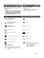
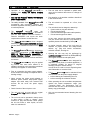
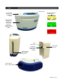
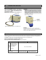
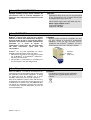
Read these operating instructions carefully prior to starting the unit. Keep this manual near the unit for future reference! PRO-II – ENGLISH Doc. No.: NP126A AC / DC Powered Negative Pressure Wound Therapy Pump System ● Instructions for Use ● General Operating Information ● Technical Data ● Warranty Rehab Technologies, LLC 1-800-237-6708 0483 0483 Table of contents 1.0 1.1 1.2 1.3 1.4 INTRODUCTION ........................................................................................................................ 3 Standard equipment .................................................................................................................... 3 Explanation of symbols and keys................................................................................................. 3 For your safety – CAUTION!...................................................................................................... 4 Illustrations.................................................................................................................................. 5 2.0 WOUND APPLICATION INSTRUCTIONS .................................................................................. 6 3.0 OPERATION .............................................................................................................................. 7 3.1 3.1.1 3.2 3.3 3.4 3.4.1 3.4.2 3.4.2.1 3.4.2.2 3.4.2.3 3.4.2.4 3.4.2.5 3.5 4.0 4.1 4.2 5.0 5.1 5.2 ® TM Preparing the Prospera PRO-II NPWT System for Operation................................................. 7 ® TM Prospera PRO-II Canister – Installation and removal instructions............................................ 7 TM Operating the PRO-II NPWT System ....................................................................................... 8 ® Continuous and Intermittent (VPT ) Operation............................................................................. 9 Settings....................................................................................................................................... 9 General description ..................................................................................................................... 9 Detailed description................................................................................................................... 10 Option Mode screen.................................................................................................................. 10 Continuous mode ...................................................................................................................... 10 ® Intermittent, Variable Pressure Therapy (VPT ) mode ............................................................... 11 Bargraph................................................................................................................................... 12 Patient mode............................................................................................................................. 13 Alarm Indicators ........................................................................................................................ 14 CLEANING AND SERVICING .................................................................................................. 15 Replacing the canister............................................................................................................... 15 General..................................................................................................................................... 15 BATTERY................................................................................................................................. 16 Charging instructions for the battery .......................................................................................... 16 Recharge the battery................................................................................................................. 16 6.0 TROUBLE-SHOOTING............................................................................................................. 17 7.0 LEGAL INFORMATION ............................................................................................................ 18 8.0 WARRANTY ............................................................................................................................. 18 9.0 DISPOSAL ............................................................................................................................... 18 10.0 ELECTROMAGNETIC COMPATIBILITY (EMC) ................................................................ 19 - 21 11.0 SPARE PARTS ........................................................................................................................ 21 12.0 TECHNICAL DATA .................................................................................................................. 22 13.0 INDEX ...................................................................................................................................... 23 The document is subject to technical alterations! PRO-II - Page 2 1.0 INTRODUCTION This manual contains important information regarding safe and effective use and operation of ® TM Prospera PRO-II . CAUTION! This device must be used by qualified and authorized staff. The user must have adequate knowledge of the specific medical application for TM which the PRO-II Negative Pressure Wound Therapy System is being applied. 1.2 1.1 Standard equipment ® Prospera PRO-II TM System: TM PRO-II pump Collection canister with integrated bacteria and carbon filter, solidifier and PVC tubing Power supply adapter Explanation of symbols and keys ”Caution: pay attention to Operating instructions“, acc. to DIN EN 980:2003. Up “Caution: pay attention to accompanying documents”, acc. to DIN EN 980:2003 Down Degree of protection: Type BF (Body Floating) OK (Enter, On) Protection class II Cancel (Off) Operating time with battery Battery full Power supply adapter is connected Battery low High pressure / Max time Battery empty Low pressure / Min time Key lock: automatically activated after 15 minutes and/or manually activated/deactivated by pressing the keys simultaneously (only when pump is running, green display) Packaging unit for TM PRO-II canister Equipment must not be disposed of with household waste. Dispose of or recycle in accordance with local regulations PRO-II - Page 3 1.3 For your safety – CAUTION! ® TM Operation of the Prospera PRO-III is possible even during the battery charging procedure. Use only with Prospera FRIWO FW 7555M/12 power supply adapter. The safety standard of the Prospera PRO-III corresponds with recognized medical and technical regulations and the guidelines relating to medical products. ® ® TM The unit must not be operated in splash water range and in locations where there is a danger of explosion. Pay attention to the ambient conditions described in the technical data. The unit should be operated on a firm, level surface. The unit should not be charged or started up: if power cable or plug are defective; if it has been dropped; if obvious defects might restrict safe operation; if it has been dropped into water. ® TM The Prospera PRO-III bears the CE identification symbol CE0483 in accordance with the EEC Medical Devices Directive – Directive 93/42/EEC and meets the basic requirements of Annex I to this Directive. ® TM The Prospera PRO-III has been designed according to EEC Directive 93/42/EEC Annex IX and has been classified as suction unit of Class lla. ® In regular intervals, parts of the unit must be checked for proper function and safety-related defects, e.g. plug and socket connections, collection canister, housing etc. Opening the unit may only be performed by ® qualified personnel authorized by DeRoyal . Only use original accessories and spare parts. The Prospera PRO-III has been designed for aspiration of body fluids in medical application; it is especially suitable for wound or surgical drainage (except for thorax suction). It must never be used to remove explosive gases and inflammable or corrosive fluids. TM The Prospera PRO-III meets the immunity to interference requirements of IEC 601-1-2/EN 60601-1-2 “Electromagnetic compatibility Medical Electrical Devices“. Electromagnetic interference and interaction are thus reduced to a minimum. ® In any case, remove the power supply adapter from the socket and have the unit checked by ® qualified personnel authorized by DeRoyal . TM ® TM The Prospera PRO-III may only be applied by persons who have been trained in its operation according to the instruction guidelines issued by the supplier or medical staff. Prior to connecting the power supply adapter, check whether the voltage corresponds with inbuilding voltage. Never connect the power supply adapter to defective power sockets. Keep power supply adapter and cable away from external heat sources. Do not cover the power supply adapter. The Prospera PRO-III must be switched off and disconnected from the power supply adapter: before cleaning and maintaining the unit; before removing the collection canister. When operating the unit at ambient temperatures outside the stated temperature range (see “Technical Data”), the performance may be reduced and the unit or the electronics and the battery may get damaged. Only use recommended wound dressing kits and protocols. Check function of the unit prior to use. The unit may only be used with the original ® TM Prospera PRO-III collection canister. The unit must not be operated in damp rooms or when taking a bath or shower. Avoid moisture on plug and switches. Never plunge the unit into water or other liquids, not even when it is switched off. PRO-III - Page 4 ® TM 1.4 Illustrations Display Pad Press down to unlock and remove the canister Self-contained disposable canister incl. connecting PVC tube, bacteria filter, carbon filter and solidifier Background colors of display pad Yellow: Pump is idle Green: Pump is running Red: Error message Tube connection Connection for PVC tubing to the patient Integrated bacteria filter, carbon filter, solidifier Disposable canister Connection for power supply adapter PRO-II - Page 5 2.0 WOUND APPLICATION INSTRUCTIONS Indications for use ® TM The Prospera PRO-II Powered Suction Pump is indicated for patients that would benefit from a suction device particularly as the device may promote wound healing. Contraindications The PRO-IITM is contraindicated in the presence of: Necrotic tissue Unexplored or non-enteric fistulas Untreated osteomyelitis Malignancy in the wound Exposed arteries, veins, or organs Precautions Precautions should be taken for patients who are or have: On anticoagulation or active bleeding Difficult wound hemostasis Close proximity of blood vessels, organs, muscle, and fascia requiring adequate protection Irradiated vessels and tissue Bony fragments Untreated Malnutrition Non-compliant ® Prospera Self-Contained Collection Canister TM ® The PRO-II pump is supplied with a Prospera built-in disposable 250 cc canister. Replace canister at a fill level of approx. 200 cc, weekly or between each patient use. Prospera® Wound Dressing Material Selection Antimicrobial gauze is the recommended choice for wound dressing material and is included in the ® Prospera Wound Dressing Kit. Always moisten antimicrobial gauze with sterile saline prior to sealing the wound with transparent dressing provided. PRO-II - Page 6 ® TM Prospera PRO-II Pump Placement TM The PRO-II unit may be placed at the patient‘s bedside. An optional carrying case is available for mobile use; however, it is the responsibility of the clinician or trained provider to determine if the patient’s condition allows for mobile use. In TM addition, the PRO-II can also be used in horizontal position. Negative Pressure Settings Lower levels of pressure settings are effective and well tolerable – for example: (a)- Continuous pressure setting of -60…-80mmHg ® (b)- Intermittent (VPT ) settings High -60…-80mmHg @ 2-5 min interval Low -20…-40mmHg @ 2-5 min interval TM Once the PRO-II pump is switched on, the pressure settings can by adjusted by a trained provider. Reminder: • Use the lowest level of pressure setting possible. All pressure settings and modalities must be prescribed by a medical provider. • Ensure that the canister is in place before TM PRO-II pump is switched on. • Check the wound dressings every 6-8 hours or sooner. Look for a wrinkled appearance at the surface of the dressing, which indicates an occlusive environment, thus maintaining proper suction. 3.0 OPERATION 3.1 Preparing the Prospera® PRO-IITM NPWT System for Operation Inspect all tubing for any splits, cuts, or other damage. Care must be taken to avoid kinks while connecting the tubing. Ensure that the canister is TM properly connected before PRO-II pump is switched on. 3.1.1 The Prospera® PRO-IITM is designed for in-patient and primarily for mobile use and is most suitable for use in low vacuum range application for medical suction procedures where secretions, blood and body fluids are 250cc or less between dressing changes. Application includes all patient care settings. Prospera® PRO-IITM Canister – Installation and removal instructions Installation of canister: Attach a new canister to TM THE PRO-II pump by aligning the bottom grooves of the canister with THE tracks on the TM PRO-II unit. Slide and push the canister FORWARD until it attaches to the suction port and the canister snap-in clip is engaged. Step 2- push canister forward to engage snap-in clip Removal of canister: While holding both the pump and the canister firmly, depress and hold the snap-in clip and gently disengage the canister TM from the PRO-II pump by PULLING THE CANISTER AWAY from the suction port. Properly discard canister and integrated PVC tubing. Step 1- depress and hold snap-in clip Step 1- align canister with pump suction port Suction port Step 2- pull away from suction port Suction port Replacement of canister: Follow installation instructions above. PRO-II - Page 7 3.2 Operating the PRO-IITM NPWT System Connect the power supply adapter to the AC outlet and to the unit. To switch the unit on, press and hold the key for 1-2 seconds until the Start screen appears: By default, the pump will then show the factory setting Continuous mode and a pressure of -80mmHg: Remove the collection canister in order to perform the tests described below. Press key to start operation. Allow to run for 10 seconds. Internal suction circuit: (system closed) TM Seal the PRO-II suction port by covering it with your thumb. The internal circuit is tight when the vacuum pressure gauge indicates -80mmHg and the error message “system closed” appears on the display. Confirm the error message by pressing the key and press the key again to stop the pump. Internal suction circuit: (system open) Press the key to turn the pump on. After 30 seconds running without canister, the error message “System open” alarm will sound. External suction circuit: Attach the collection canister to the pump and press the key to turn the pump on (see internal suction circuit). If there is a leakage, the error message “check dressing seal” alarm will sound. External components may be checked by sealing the end of the tubing circuit and following the same procedure as above. PRO-II - Page 8 NOTE! TM If the PRO-II passes the internal suction circuit check but not the external suction check then a leak is present in the external circuit. Review the external suction circuit step by step, from the pump to the patient, to find where any leaks occur. Overflow Protection Device/Bacteria Filter TM The PRO-II pump uses an integrated bacteria filter (inside the canister) for protection of the pump against overflow and the spread of aspirated microorganisms. Only use the original Prospera® TM PRO-II collection canister with integrated filter. In case of an application error, this integrated bacteria filter will prevent fluid and microorganisms from entering the interior of pump. If liquid reaches this filter, suction will no longer be possible and the error message “system closed” will appear repeatedly. In addition, an activated carbon filter is integrated in the canister for odor control. Prospera® Suction Canister ® canister should be changed and Prospera discarded when full, weekly or between patient use. Cleaning and Disinfecting Follow facility policies and guidelines concerning cleaning and disinfecting. (Also refer to sections 4.1 and 4.2). Housing The outside of the pump should be cleaned with a damp cloth. Cleaning agents and disinfectants should be used in a diluted form. Suction Canister and Tubing ® TM The Prospera PRO-II canister and all tubing are disposable and should never be autoclaved. 3.3 Continuous and Intermittent (VPT®) Operation TM The PRO-II is designed to operate in Continuous or Intermittent (VPT® - Variable Pressure Therapy) modes. Continuous: TM PRO-II is pre-set to a low vacuum pressure. When the pump is switched on, the vacuum is generated up to the set target value and is then controlled and kept at this level. Low vacuum pressure values may be adjusted by the medical staff or by the trained personnel as needed. WARNING: Universal precautions should be observed when TM operating or transporting the PRO-II pump and/or disposing of all accessories. Routine Maintenance and Inspection TM The PRO-II system and components should be visually inspected prior to each use. Battery Operation TM The PRO-II battery will provide best performance when fully charged. The TM PRO-II battery charges when plugged into AC power both during operation and when switched off and not in use. ® Intermittent (VPT ): Intermittent VPT is Prospera’s advanced technology which allows the provider to customize the pressure and time interval settings depending on the prescribed requirements. When the battery charging indicator is displayed TM on LCD, the PRO-II battery will start charging. TM The PRO-II will sound an audible signal indicating a low battery (approx. 25% left in battery time). The unit should be plugged into AC power immediately. The PRO-IITM should be stored at 23°F to 95°F (-5°C to 35°C) for optimal performance. CAUTION! All parameters should be programmed into the TM PRO-II unit by trained personnel and based on medical provider’s order. 3.4 Settings CAUTION! ® All adjustable settings, such as vacuum pressure values, time intervals during intermittent (VPT ) mode and all other settings may only be performed by trained provider/personnel and by prescribed orders. NOTE: The selected settings remain stored after switching off the pump. When switching on again, the unit will default back to the previously prescribed pressure and time settings. 3.4.1 General description To reach the Option Mode menu, switch on the pump with the key. Immediately after the display screen is illuminated, hold down both arrow keys simultaneously and continue holding down for a few seconds until the “Option Mode” menu screen appears. Use the keys to navigate the menu. Operating modes, target vacuum pressure values and time values can then be adjusted by means of the four display pad keys. The respective entry is confirmed with key or cancelled using the key. the After having finished the settings, confirm and exit the Option Mode menu and store the settings by pressing the key. If the treatment must be interrupted, stop the pump by pressing the key. (Yellow screen). To resume, start the pump by pressing the key again. (Green screen). TM To switch off the PRO-II : Press and hold down the key for 3 seconds. PRO-II - Page 9 3.4.2 Detailed description 3.4.2.1 Option Mode screen Option Mode screen: The cursor points to the desired operating mode ® (Continuous or Intermittent (VPT )) or to the language settings. Use the keys to move the cursor to the respective mode and confirm your selection with the key. Note: To switch from Continuous mode to Intermittent ® (VPT ) mode, after having confirmed a mode by key, the pump must be turned off and pressing the on again in order to activate the “Option Mode”. Language Settings: Use the keys to move the cursor to the respective language and confirm your selection with the key. 3.4.2.2 Continuous mode NOTE: If pump is idle: Display has a yellow background color. If pump is running: Display has a green background color. If pump indicates an error message: Display has red background color . yellow: yellow: green: Continuous operation with the prescribed pressure value. Continuous pressure = -10…-200mmHg (in steps of 5) Option Mode Continuous: Use the keys pressure. The Start the pump by pressing the value is Operating Screen: To stop the pump press the PRO-II - Page 10 pressure key. to set prescribed confirmed with key. key again. the ® 3.4.2.3 Intermittent, Variable Pressure Therapy (VPT ) mode ® Intermittent (VPT ) operation: Changeover between two phases with different prescribed pressure and time interval settings. Option Mode Intermittent (VPT®): Pressure Range High Pressure = -20...-200mmHg (in steps of 5) Low Pressure = -10...-100mmHg (in steps of 5) The Low pressure setting can not be higher than the High pressure setting. • Time Range Max Time = duration for High pressure = 0.5...10.0 min (in steps of 0.5 minutes) Min Time = duration for Low pressure = 0.5...10.0 min (in steps of 0.5 minutes) This display confirms the high and low pressures ® and time settings for Intermittent (VPT ) Start the pump by pressing the key. To stop the pump press the key again. Operating screen: ® Intermittent (VPT ) / high pressure phase: The timing bar progresses from left to right as the pressure increases to high pressure setting. ® Intermittent (VPT ) / low pressure phase: The timing bar reverses from right to left as the pressure decreases to low pressure setting. PRO-II - Page 11 3.4.2.4 Bargraph The Bargraph feature is automatically displayed on the screen for 60 seconds after start of the pump in ® either Continuous or Intermittent (VPT ) Mode. To display the bargraph again, press either of the keys and it will remain on for additional 60 seconds. Bargraph explanation: The vertical bargraph is used as a guide for the provider to measure the effectiveness of the dressing seal. Once the pump is turned on, the gauge on the graph will start rising. The following demonstrates the various outcomes: too tight range optimal range not tight range 1. If the bar rises to the level marked as “not tight”, this indicates leak in the dressing seal and therefore ”check dressing seal” alarm will sound. 2. If the bar rises beyond the level marked as “too tight” and fills the entire bar, this indicates dressing is too tight, no air flow and the “system closed” alarm will sound. 3. If the bar rises and remains steady at the halfway mark, this indicates the most optimal and desired seal . The provider may choose to customize the sensitivity levels for “system closed” and “check dressing seal” alarms depending on the patient, location of the wound and the amount of exudate. Note: The Bargraph will not display or work if the sensitivity for closed system alarm is set to 1. PRO-II - Page 12 3.4.2.5 Patient mode The default key is: 1111 To reach the Patient Mode, switch on the pump with the key. Immediately after the display screen is illuminated, hold down the both keys and simultaneously and continue holding down for a few seconds until the “Authorization” menu screen appears. (blue screen) Use the keys to set the first number to 1 then press the key to confirm and proceed to next number. Repeat this step for all 4 numbers. System closed sensitivity Use the keys to set the sensitivity. Range from 2 to 9 2-----------------------5----------------------9 lower sensitivity (delayed alarm) default higher sensitivity (faster alarm) Sensitivity of “1” detects only a full canister or a blocked filter Leakage sensitivity Use the keys to set the sensitivity. Range from 1 to 5 1-----------------------2----------------------5 lower sensitivity (delayed alarm) default higher sensitivity (faster alarm) Patient Runtime / Compliance This feature counts (total hours) when the pump is running or display screen is green. To reset the counter to zero, press and hold down the key for 3 seconds. PRO-II - Page 13 3.5 Alarm Indicators Note: Alarm messages appear with red background color. Error Message: Status: Possible Causes: Remedy: • Alarm on • Motor off • Termination of current operating mode Motor has run for 30 seconds without generating pressure • Press key to remove the error message and to silence the alarm • Check correct connections • Re-start the pump System closed (message appears within 5 minutes – depending on the error location) • Alarm on • Current operating mode continues in the background Canister full (filter closed) • Press key • Switch unit off Tube is kinked (near the dressing) • Replace the canister Battery low • Alarm on • Current operating mode continues in the background Low battery charging condition Warning message from battery pack • Alarm on • Motor off • Termination of current operating mode Check dressing seal System open Pump is switched on but not running (canister is not connected) • Check the tube • Press key or • Connect power supply adapter • Press key Battery is empty • Connect power supply adapter • Alarm on • Current operating mode continues in the background Dressing is not tight • Press key • Switch unit off (tube or canister not correctly connected or leaks in the dressing) • Trouble shoot the dressing and tubing • Alarm sounds after 15 minutes Pump was not started • Press key to remove the error message and to silence the alarm • Re-start the pump PRO-II - Page 14 4.0 CLEANING AND SERVICING 4.1 Replacing the canister ® TM Turn off the Prospera PRO-II and unplug it from AC power. Remove the collection canister from the pump. Properly discard canister and integrated PVC tubing. Replace with a new canister. (see section 3.1.1) Snap-in clip CAUTION! Follow facility protocol for disposal of hazardous material. In regular intervals, parts of the unit must be checked for proper function and safetyrelated defects, e.g. power supply adapter, socket connections, canister, etc. PRO-II TM without canister warranty tamper proof seal How to remove the canister (see section 3.1.1) Solidifier: The aqueous fluid in the canister is gelled by the solidifier. This prevents leakage during handling and disposal of this liquid medical waste. 4.2 General All parts that come into contact with the wound exudate must be disposed according to facility guidelines. TM The PRO-II pump may be cleaned and disinfected as shown in the following table. Observe the manufacturer’s instructions for disinfection. Do not use disinfectants containing acetone. Gloves should be worn during disinfecting (e.g. disposable gloves). Disposable parts Part Collection canister (including integrated PVC tubing and bacteria filter) Cleaning Disinfecting Re-use not permitted! Dressing Pump casing Wipe with a moist cloth Wipe with disinfectant PRO-II - Page 15 5.0 BATTERY Rechargeable battery 7.4V, 4.4Ah - lithium-ion battery Charging time of empty battery Charging time of ½ empty battery 6-7 hours 3-3.5 hours Operating time 5.1 DC operation: approx. 24…48 hours, depending on use Charging instructions for the battery TM It is strongly recommend to charge the battery completely upon receipt of the PRO-II and prior to first use. Repeat this charging procedure during the first applications in order to reach the maximum number of charging cycles (about 500 cycles). TM The PRO-II is equipped with a lithium-ion battery. Compared to traditional batteries, lithium-ion batteries have a lower, but temperature-dependent, self-discharging rate of 3-10% per month. Storage and usage of the battery in the PRO-II under “Technical Data” . TM must be within the temperature ranges stated in the section Lithium-ion batteries do not suffer from the memory effect. After initial charging (see above), they can be recharged at any time without damage, although frequent short-time charging should be avoided. TM The battery of the PRO-II is protected against “total discharge” and “overheating” during charging. Nevertheless, the above charging instructions must be adhered to. If, due to extreme ambient conditions, battery temperature increases above the limit, charging will temporarily be interrupted in order to allow the battery to cool down. This is to enhance the battery’s life. 5.2 Recharge the battery To re-charge the battery connect the power supply adapter to the AC outlet and to the ® TM Prospera PRO-II pump. Option: Use the optionally available car connecting cable to operate and charge the unit with a 12V on board supply system. The battery can be charged in running mode, idle mode and also when the pump is in off mode as shown in the display examples. NOTE: During the off mode once the battery is fully charged the display screen will go from a light yellow to blank screen. full battery half full battery empty battery power supply adapter is connected PRO-II - Page 16 light yellow screen battery charging when pump is in off mode yellow screen battery charging in idle mode green screen battery charging in running mode 6.0 TROUBLE-SHOOTING ® TM The Prospera PRO-II was subjected to a thorough quality control and inspection before shipment. However, if there is some malfunction, you may be able to solve the problem using the following instructions. Problem Possible causes Remedy Unit does not start • Battery is empty • Connect the power supply adapter • Unit is still in the setting mode • Complete the settings • Bacteria filter is moist (canister full) • Replace the canister • Bacteria filter inside the canister is contaminated/moist • Replace the canister • Leakage within the suction line • Check proper fit of canister and tube connections • Assess dressing • Charge the battery Insufficient performance • Battery almost empty If the problem still persists, contact the service. No suction • Bacteria filter inside the canister is contaminated/moist • Replace the canister • Canister full • Replace the canister • Tubing is kinked • Check that the tubing is properly placed and connected If the problem still persists, contact the service. PRO-II - Page 17 7.0 LEGAL INFORMATION Improper handling of this device releases the manufacturer from its warranty obligation. In particular, these operating instructions must be followed. CAUTION! Operational safety of the unit can be guaranteed by the manufacturer only if original accessories and original spare parts are used. For the power supply via the AC outlet, only use: Power supply adapter FRIWO (Type: FW 7555M/12) Product No. NP-2002 8.0 WARRANTY ® DeRoyal warrants your new PRO-II™ against defects in material and workmanship during the warranty period of one (1) year from the date of purchase. This period is neither extended nor presumed as a result of repairs or replacements carried out. The warranty does not cover accessories, spare parts and consumables. ® DeRoyal can be held responsible for safety, reliability and performance of the unit only if: Maintenance and repairs are exclusively carried out by DeRoyal® or by DeRoyal® authorized personnel or technicians. The product is used properly in accordance to the instructions in this operating manual. 9.0 CAUTION! Warranty claims will not be accepted if the unit has been opened or repaired by unauthorized individuals, if the unit has not been used in ® accordance with Prospera guidelines and if the special tamper proof seal is missing or broken. warranty tamper proof seal Disposal TM When the PRO-II is ready for final disposal, the components must be discarded properly observing the applicable waste-control regulations. In doing so, make sure that the materials are in clean condition and that they are carefully separated. Parts of the collection canister, tubes and filter may be disposed of as normal waste while the basic unit TM is disposed of as electric scrap. The PRO-II does not contain any hazardous materials. The housing is marked with a material abbreviation and can be recycled completely. PRO-II - Page 18 CAUTION! Pay attention to country-specific regulations, especially with regard to disposal of used batteries. 10.0 ELECTROMAGNETIC COMPATIBILITY (EMC) The Prospera® PRO-IITM meets the immunity to interference requirements of IEC 601-1-2/EN 60601-1-2 ”Electromagnetic compatibility - Medical Electrical Devices“. Electromagnetic interference and interaction are thus reduced to a minimum. Table 1 Guidance and Manufacturer’s Declaration – Electromagnetic Emissions ® Prospera suction units of the PRO series are intended for use in the electromagnetic environment specified below. The customer or user should ensure that they are used in such an environment. Emissions Test Compliance Electromagnetic Environment Guidance ® RF Emission Prospera suction units of the Class B according to CISPR 11 PRO series are suitable for use in all Emission of harmonic oscillations facilities including those in residential Not applicable according to IEC 61000-3-2 areas and those directly connected to a public utility network also supplying Emission of voltage fluctuations/flickers Not applicable buildings used for residential according to IEC 61000-3-3 purposes. Table 2 Guidance and Manufacturer’s Declaration – Electromagnetic Immunity Prospera ® suction units of the PRO series are intended for use in the electromagnetic environment specified below. The customer or user should ensure that they are operated in such an environment. Electromagnetic Environment Immunity Test IEC 60601 - Test Level Compliance Level - Guidance Floors should be made of wood Discharge of static or concrete or feature ceramic ±6kV contact discharge ±6kV contact discharge electricity (ESD) tiles. If the floor covering consists of synthetic material, according to ±8kV air discharge ±8kV air discharge IEC 61000-4-2 the relative humidity should be at least 30%. Electrical fast transients (EFT) / bursts according to IEC 61000-4-4 Surges according to IEC 61000-4-5 Voltage dips, short interruptions and voltage variations on power supply input lines according to IEC 61000-4-11 Supply frequency magnetic field (50 Hz) according to IEC 61000-4-8 ±2kV for AC power lines ±2kV for AC power lines ±1kV for input and output lines ±1kV for input and output lines ±1kV differential mode ±1kV differential mode ±2kV common mode voltage not applicable <5% UT (>95% dip of the UT) for ½ cycle <5% UT (>95% dip of the UT) for ½ cycle 40% UT (60% dip of the UT) for 5 cycles 40% UT (60% dip of the UT) for 5 cycles 70% UT (30% dip of the UT) for 25 cycles 70% UT (30% dip of the UT) for 25 cycles <5% UT (>95% dip of the UT) for 5s <5% UT (>95% dip of the UT) for 5 s 3 A/m 3 A/m The quality of the supply voltage should be the same as the voltage of a typical business or hospital environment. The quality of the supply voltage should be the same as the voltage of a typical business or hospital environment. The quality of the supply voltage should be the same as the voltage of a typical business or hospital environment. If the user/operator of the PRO units requires the continuation of functionality after power interruptions/disruptions, it is recommended to provide units with power from an uninterruptible power supply or a battery. Magnetic fields of the mains power frequency should comply with the typical values of business and hospital environments. Note: UT is the mains alternating voltage before applying the test levels. PRO-II - Page 19 10.0 ELECTROMAGNETIC COMPATIBILITY (EMC) Table 3 Guidance and Manufacturer’s Declaration – Electromagnetic Immunity ® Prospera suction units of the PRO series are intended for use in the electromagnetic environment specified below. The customer or user should ensure that they are operated in such an environment. Electromagnetic Environment Immunity Test IEC 60601 - Test Level Compliance Level Guidance Portable and mobile wireless devices should not be used in closer ® proximity to the Prospera suction units of the PRO series (including cables/lines) than the recommended safety distance calculated based on the transmitting frequency and the applicable formula. Recommended safety distance: d= 1.2 √P Conducted RF interference quantities according to IEC 61000-4-6 Radiated RF interference quantities according to IEC 61000-4-3 d= 1.2 √P for 80 MHz to 800 MHz d= 2.3 √P for 800 MHz to 2.5 GHz 3 Veff 150 kHz to 80 MHz 3 Veff 3 V/m 80 MHz to 2.5GHz 3 V/m with P as the rated output of the transmitter in watts (W) according to the information provided by the manufacturer of the transmitter and d as recommended safety distance in meters (m). Field strengths from fixed RF transmitter as determined by an a electromagnetic site survey should be less than the compliance level in each b frequency range . Interference is possible in the proximity of devices featuring the following pictograph. NOTE 1 The higher frequency range applies in case of 80 MHz and 800 MHz. NOTE 2 These guidelines may not be applicable in all cases. The spread of electromagnetic quantities differs depending on the absorption and reflection of buildings, objects, and people. a The field strength of stationary transmitters such as base stations of mobile phones and land mobile devices, ham radio stations, AM and FM radio, and TV broadcasters are theoretically not 100% predictable. A site study is recommended to determine the electromagnetic environment as it pertains to the stationary transmitters. If the measured field strength at ® the proposed installation and operation site of the Prospera suction units of the PRO series exceeds the concordance levels listed above, the units should be monitored to document proper functionality and operation as intended. Additional measures might become necessary, e.g. modifying orientation or a different location for the units, if unusual performance characteristics are observed. b The field strength should be less than 3 V/m for the frequency range of 150 kHz to 80 MHz. PRO-II - Page 20 10.0 ELECTROMAGNETIC COMPATIBILITY (EMC) Table 4 Recommended safety distances between portable and mobile RF telecommunications devices ® and Prospera PRO series suction units. PRO series suction units are intended for use in an electromagnetic environment where RF interference quantities are controlled. The user/operator of the PRO suction units can help prevent electromagnetic interference by maintaining a minimum distance between portable and mobile RF telecommunications devices (transmitters) and the PRO suction units – depending on the output power of the communication device listed below. Safety distance based on the transmitting frequency m Rated output of the transmitter W 0.01 0.1 1 10 100 150 kHz to 80 MHz d= 1.2 √P 80 MHz to 800 MHz d = 1.2 √P 800 MHz to 2.5 GHz d = 2.3 √P 0.12 0.38 1.2 3.8 12 0.12 0.38 1.2 3.8 12 0.23 0.73 2.3 7.3 23 The safety distance d in meters (m) for transmitters with a max. rated output not listed in the table above can be calculated by applying the corresponding formula in the respective column. P is the max. rated output of the transmitter in watts (W) as specified by the transmitter manufacturer. NOTE 1 The higher frequency range applies at 80 MHz and 800 MHz. NOTE 2 These guidelines are probably not realizable in all cases. The distribution and spread of electromagnetic quantities differs depending on the absorption and reflection of buildings, objects, and people. 11.0 SPARE PARTS CAUTION! Regularly check your stock for completeness of these parts. CAUTION! Operational safety of the unit can be guaranteed by the manufacturer only if original accessories and original spare parts are used. REF Canister set: Including bacteria filter, carbon, solidifier and PVC tubing .....NP-1004 Power supply adapter, FRIWO (Type: FW 7555M/12) ...............................NP-2002 PRO-II - Page 21 12.0 TECHNICAL DATA Air-flow rate of pump Negative pressure Collection canister 8 liters/min max. -200mmHg; Conversion factor: 1kPa ~ 7.5mmHg Disposable canister systems Suction tubing Various drainage systems, depending on supplier and specific application. Type and kind of use are determined by the medical staff. Nominal voltage of power supply adapter Maximum load current Mains frequency of power supply adapter 100 - 240V primary / 12VDC secondary 1.25A 50 / 60Hz Nominal voltage of electronic circuit board 12V Power consumption 15W (charging and operation) / 10W (charging only) Current consumption 1.25A Rechargeable battery Charging time of empty battery Charging time of ½ empty battery Dimensions (W x H x D) 7.4V, 4.4Ah – lithium-ion battery 6-7 hours 3-3.5 hours 215 x 165 x 90mm (8.4 x 6.5 x 3.5 inch) Weight (basic unit) 1.3kg (2.65 lbs.), with canister Operating time AC operation: continuous operation DC operation: approx. 24…48 hours, depending on use Degree of protection acc. to IEC 601-1 Type BF Risk class according to 93/42/EEC, IX Protection class according to IEC 601-1 IIa II Medical Suction Unit WITH RESPECT TO ELECTRICAL SHOCK FIRE, AND MECHANICAL HAZARDS ONLY IN ACCORDANCE WITH UL 606011/CAN/CSA C22.2 No. 601.1 3KCX UL Classification CE mark Sound emission CE0483 35 dB (A) Ambient conditions Transport/storage: -10°C – +60°C (14° F – 140° F) Operation: +5°C – +35°C (41° F – 95° F) Recommended charging temperature: +15°C – +30°C (59° F – 86° F) 5 up to 80% relative humidity, non-condensing Atmospheric pressure: 860hPa…1060hPa REF 10802 PRO-II - Page 22 13.0 INDEX O A AC outlet air-flow rate of pump alarm indicators ambient conditions 15, 18 22 14 4, 16, 22 operating screen operating time operational safety option mode overflow protection device 10, 11 3, 16, 22 21 10, 11 8 B background color bacteria filter bargraph battery battery empty battery full battery low battery operation 10 5, 8, 17 12 16, 17, 22 3, 14, 16, 17 3, 16 3, 14 9 P patient mode patient runtime power supply adapter precautions proper function protection class pump placement PVC tubing 13 13 3, 4, 5, 8, 16, 18, 22 6, 9 4 3, 22 6 15 C 4, 6, 8, 17, 18, 22 7, 15 16, 21 3, 5, 8 6 16, 22 14 4 4, 15 13, 19, 20 8, 9, 10, 12 6 canister canister, how to remove it car connecting cable carbon filter carrying case charging time check dressing seal class lla cleaning compliance continuous mode contraindications D degree of protection disinfecting disposal dressing 3, 22 8, 15 15 6, 15 Q qualified personnel R re-start pump (error message) risk class sensitivity gauge servicing settings solidifier spare parts surgical drainage symbols system closed system open 13 15 9 3, 15, 21 4, 21 4 3 8, 12, 13, 14 8, 14 T 4 4, 19, 20, 21 8, 14 I IEC 601-1-2/EN 60601-1-2 indications for use intermittent VPT® mode 14 22 S E EEC Directive electromagnetic compatibility error message 4 4, 19 6 9, 11, 12 tamper proof seal technical data timing bar trouble-shooting tubing 15, 18 22 11 17 7, 8, 17, 22 V vacuum VPT® Variable Pressure Therapy 22 9, 11, 12 K key lock L leakage legal information 8, 13, 15, 17 18 N negative pressure settings W 3 warranty warranty claims warranty obligation warranty period waste-control regulations wound dressing material wound exudate 18 18 18 18 18 6 15 6 PRO-II - Page 23