1
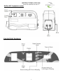
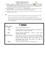
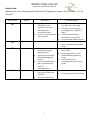
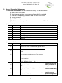
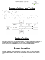
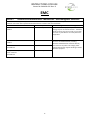
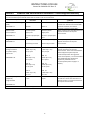
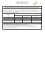
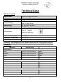
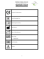
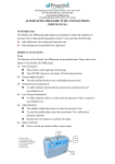
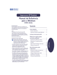
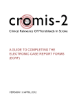
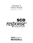
INSTRUCTIONS FOR USE Control #: SMI-420-435 Rev. B User’s Manual BluFlex DVT Prophylaxis System 0 INSTRUCTIONS FOR USE Control #: SMI-420-435 Rev. B Warning 1. 2. 3. 4. Connect the Master Control unit to a proper power source. Do not use the pump in the presence of uncontained flammable liquids or gasses. Keep the pump and garment away from sources of liquid and open flames. Keep the pump and garment away from sharp objects. Caution Product should be used in accordance with hospital policy 1. The control unit should only be repaired by an authorized distributor. 2. Do not drop the control unit; store it in direct sunlight or extreme cold conditions. Safety These usage and safety guidelines are IMPORTANT! Please follow them carefully. General Use 1. Carefully unpack the contents of the pump package. 2. Connect the master control unit to a proper power source. 3. Do not use or store your pump any of the listed environments – Do not drop the control unit or store it in direct sunlight or extreme cold conditions. Do not use the pump in the presence of uncontained flammable liquids or gasses. Keep the pump and garments away from sources of liquid and open flames. Keep the garments away from sharp objects. Keep the pump and garments away from heating devices. Storage Environment Specification It is recommended that the following guidelines be used whenever the system is being stored or transported to another location: Temperature limitations: 5°C ~ 60°C Relative humidity: 30% ~ 75% Control Unit 1. Check power cord and plug for abrasions and excessive wear. 1 INSTRUCTIONS FOR USE Control #: SMI-420-435 Rev. B 2. Plug in the unit and verify airflow from the hose connection ports. 3. Place in a dry storage area when not in use. Product Description The BluFlex DVT Prophylaxis System is a non-invasive intermittent pneumatic compression system that aids in prevention and reduction in incidence of deep vein thrombosis (DVT), a potentially life threatening condition, which can lead to pulmonary embolism. The system consists of a pump and soft pliable compression single patient use garments for leg or foot compression. The pump supplies compression on a pre-set inflation pressure of 40mmHg for calf and thigh compression, and 80mmHg for foot compression. Pressure in the garments is transferred to the extremities, augmenting venous blood flow, thus reducing stasis. This process also stimulates fibrinolysis; further reducing the risk of early clot formation. Please note: It is NOT RECOMMENDED that patients with following symptoms use this product without consulting a physician. Caution Contraindications for use: The use of the BluFlex DVT Prophylaxis System is NOT RECOMMENDED in the following conditions – 1. Severe congestive cardiac failure. 2. Severe arteriosclerosis or other ischaemic vascular disease. 3. Extreme deformity of the limbs. 4. Known or suspected deep vein thrombosis. 5. Known or suspected Pulmonary Embolism. 6. Any local condition in which the garments would interfere: i.e. i. ii. iii. iv. Gangrene Dermatitis Untreated or infected wounds Recent skin grafts 2 INSTRUCTIONS FOR USE Control #: SMI-420-435 Rev. B BluFlex DVT Prophylaxis System Control Unit Features 3 INSTRUCTIONS FOR USE Control #: SMI-420-435 Rev. B Operating Instructions To operate the BluFlex DVT Prophylaxis System the following steps should be followed: Please read this instruction manual in its entirety before setting up. 1. Plug pump into an appropriate electrical outlet. DO NOT SWITCH ON. 2. Position the pump on flat surface or suspend the pump at the foot of the bed using the swingout hooks. 3. Place garment(s) on the legs or feet, ensure the male Velcro does not touch the patient’s skin. Use only foot or only calf/thigh for dual garment therapy; don’t mix foot with calf/thigh garment. 4. Snugly wrap garment, making sure the inflatable bladder is in the correct orientation. Garments are labelled to indicate correct positioning. When correctly positioned, secure with the tabs. Garments should fit securely but not tightly around the patient’s extremity. Repeat the procedure for the other limb. If only one garment is used, disconnect one of the hoses from the pump. 5. Air tubing is required to connect garment(s) to the pump. Attach the garments to the air tubing using the white snap lock connectors. Each tube has a male end connector at one end and a female end connector at the other. The female end (large white connector) will fit to the male end (small white connector) that is on the garment. Make certain that a “click” sound is heard to ensure a solid connection. 6. Attach the other end(s) of the air tubing (male end) to the large white female connector(s) on the pump. Make certain that a click is heard with each snap lock connection. If you need to disconnect the tubing, press the silver tab on large white (female) connector and pull apart. 7. Press the on/off switch to turn pump on. 8. Pump will start initialization process for approximately 10 seconds. 9. Pump will automatically detect Single/Dual garment/s during initialization process. The pump is set to default to Dual Calf/Thigh garments. 10. To switch to Foot Therapy, while pump is in operation press “FOOT” button for approximately 3 seconds until “FT” is displayed. To switch back to Calf/Thigh Therapy while the pump is in operation, press “CALF/THIGH GARMENTS” for approximately 3seconds until “LEG” is displayed. 11. If the pump is in operation on Dual Garments Therapy and you want to change to Single Garment Therapy, disconnect one of the hoses from the pump and press “SINGLE GARMENT.” The pump will start initialization process for 10 seconds and the Single Garment Therapy will begin. 12. If the pump is in operation on Single Garment Therapy and you want to change to Dual Garment Therapy, attach the second hose and garment and press “SINGLE GARMENT.” The pump will directly start the Dual Garment Therapy. 4 INSTRUCTIONS FOR USE Control #: SMI-420-435 Rev. B 13. TIMER – To activate the TIMER, switch the pump and timing will commence. The TIMER reflects HOURS of compression. If compression is interrupted i.e. the patient is removed from therapy, and the pump is switched off at the power switch; the timer will suspend timing until the patient is reconnected to therapy and therapy is continued. 14. RESETTING TIMER – to reset the timer press “RESET TIMER” for 5 seconds and it will reset. Always reset timer prior to new therapy to ensure correct time is measured. 15. Disconnect Device:Switch the device off, disconnect from power supply and remove garments from the patient. Note: Ensure that there are no kinks in the tubing and the connectors are properly locked. Never apply or remove the garments while inflated as this may damage to the garments. The parts and/or accessories supplied are specifically designed for use with the BluFlex DVT Prophylaxis System control unit. Use of other products in conjunction with the system is not recommended. Caution Indicator Lights: Green - Illuminated to indicate power on. Amber - Flashing indicates a fault has been detected. An audible alarm will follow after 5 minutes visual alarm. Blue- Flashing indicates initialization in process. window will show (INT). Blue LED Display - TIMER - Upper display Upper display illuminated to indicate when Calf/Thigh (LEG) or FOOT (Ft) is activated. Lower display illuminated to indicate pressure being delivered and alarm signals of low pressure(LO), high pressure (HI), garment error (GE) and fault(F) – redirect for service. Indication of therapy time in hours from last reset. 5 INSTRUCTIONS FOR USE Control #: SMI-420-435 Rev. B Alarm Codes Indicates the error information for BluFlex DVT Prophylaxis System, these include: - LO, HI, GE and F. Alarm Codes LO Status Low Pressure Description Leg pressure is less than 40mmHg or Foot pressure is less than 80mmHg after 2 consecutive cycles. Air hose is disconnected from garment. Troubleshooting HI High Pressure Air hose is kinked. GE Garment Error Garment is not connected to pump during start up. Garments are not fully deflated during each restart. The initialization failed due to possible kinks from air hoses/garments. Pressure is greater than set pressure after two inflations. Electrical malfunction. F System Failure 6 Check garment application is not too loose or too tight. Check for air leaks from air hoses/garments. Replace if faulty. If hose is disconnected, connect hose to garment. Turn the pump off and restart. Check air hoses/garments for kinks. Undo kinks and restart pump. Connect garments to pump and restart. Ensure garments are fully deflated before restarting pump. Undo kinks from air hoses/garments and restart pump. Check air hose connections. Turn the pump off and restart. INSTRUCTIONS FOR USE Control #: SMI-420-435 Rev. B Garment Application Instructions BluFlex DVT Prophylaxis System Garments are 100% Latex FREE Instructions for use: 1. Plug the BluFlex DVT Prophylaxis control unit into a suitable electrical outlet. 2. Connect Air hoses to the pump. 3. Connect Garments to the air hose. A click confirms proper connection. 4. Place the garments on the patient, ensuring that male Velcro does not contact the patient's skin. Use only foot or only calf/thigh for dual garment therapy; don’t mix foot with calf/thigh garment. 5. Ensure a snug fit. Place two fingers around the back of the garment to ensure the garment is not too tight. Routinely inspect the patient’s feet, for proper circulation, once compression commences. 6. TURN THE PUMP ON, the power indicator light will illuminate. A “beep” sound confirms operation. Contraindications & Cautions Do not use the BluFlex DVT Prophylaxis where increased venous or lymphatic return is not desired. The BluFlex DVT Prophylaxis System could be contraindicated and should not be used by persons with known or suspected deep vein thrombosis, pulmonary oedema, congestive heart failure, severe arteriosclerosis, thrombophlebitis, or active infection. Do not use on persons with painful and sensitive extremities, where the garment will interfere with gangrenous limbs, on persons with vein ligation or recent skin grafts, or extreme deformity of the leg. Note: If you are unsure of any contraindications please refer to the patient’s physician before using the BluFlex DVT Prophylaxis system. Tubing Set Compatibility The garments connect to the Pump via the Tubing Sets provided with the Pump. The following is the recommendation but the caregiver can still select the tubing type based on the situation. Note: Do not connect multiple Tubing Sets together Item Recommendation # Replacement tubing, 60” 610 Recovery Room Replacement tubing, 120” 610L Operation Room Item 7 INSTRUCTIONS FOR USE Control #: SMI-420-435 Rev. B Cleaning The pump: The casing of the pump is manufactured from ABS plastic. If soiled it can be wiped down with a sodium hypochlorite solution to dilution of 1000ppm or any EPA approved, hospital grade disinfector The control unit (face) should also be cleaned weekly (or as often as hospital protocol requires) using a damp soft cloth and mild detergent. (Switch off the electrical supply to the pump and disconnect the power cord from the main supply before cleaning and inspection) Caution Do not use phenol based cleaning solutions. Switch off the electrical supply to the pump and disconnect the power cord from the main supply before cleaning and inspection. Garment Cleaning: After patient use, save garments for reprocessing and place in designated collection containers. Periodic Maintenance WARNING: Make sure the unit has been removed from the mains/power supply by removing the mains/power supply from the socket. CAUTION: Static Sensitive Devices - Electrostatic discharge can seriously damage the control and power supply PCB assemblies. No daily maintenance is required. Aside from routine cleaning and disinfecting, routine checks and optional annual preventative maintenance, only authorized technical personnel should service equipment. If the ‘tamper-proof seal’ on the bottom of the pump is compromised, customer will be charged a user-damage fee. 1. Routine Checks a) Inspect the control unit for external damage to case, controls, and connections. b) Inspect power cord for damage c) Test all controls 8 INSTRUCTIONS FOR USE Control #: SMI-420-435 Rev. B 2. Annual Preventive Maintenance Preventive maintenance can be carried out every 12 months. Check: a) Case is free from debris b) Electrical connections are secure and completely insulated c) Tubes are completely pushed on and are free from kinks d) Wiring is intact e) Air is alternating f) Outlet tubes and snap-lock connectors are secured and fitted correctly Qualitative Check: Item Pass Fail Qualitative Tasks Service 1.1 Chassis / Housing 1.2 Mount / Fasteners 1.3 Hooks 1.4 AC Plug / Receptacles 1.5 Alarm Light (yellow) 1.6 Labeling Quantitative Check: Item Pass Fail Quantitative Tasks Service 2.1 Pressure for Foot is 75-100mmHg @ 120V 60Hz. 2.2 Pressure for Calf/Thigh is 35-55mmHg @ 120V 60Hz. 2.3 Can alternate One Garment or Two Garments 2.4 12 sec inflation – 48 sec -Deflation /rest A___ B___. 2.5 Possible air leak from The pump displays the low pressure alarm code tubing connection or - LO compressor. 2.6 The pump displays the high pressure alarm code Possible kinked tubing. -HI 2.7 The pump displays garment error code - GE 9 Possible incorrect garment configuration. INSTRUCTIONS FOR USE Control #: SMI-420-435 Rev. B Pressure Settings and Testing Pre-set inflation pressure settings are as follows: Calf and Thigh — 40 mmHg (nominal) Foot — 80 mmHg (nominal) If needed, pressure verification testing can be done as follows: Setup equipment as shown below, making sure there are no kinks in the tubing. Use mercury pressure gauge. Garments have to be wrapped on objects which have “Leg” or “Foot” shapes. Reference garment application instructions for more details. Factory Testing Each pump’s functionality has been factory-tested. The tamper-proof seal at the bottom of the pump designates when the pump was last tested. If the seal is compromised, your service warranty will be voided and you will be charged a user damage fee. Double Insulation Although the BluFlex pump is classified as an IEC Class 1 Device, the pump is of double insulation design, and the design has been approved by safety testing report issued by TUV. 10 INSTRUCTIONS FOR USE Control #: SMI-420-435 Rev. B Waste Disposal This Product has been supplied from an environmentally aware manufacturer that complies with the WEEE. This product may contain substances that could be harmful to the environment if disposed of in places (landfills) that are not appropriate according the legislation. Please be environmentally responsible and recycle this product through your recycling facility at its end of life. 11 INSTRUCTIONS FOR USE Control #: SMI-420-435 Rev. B EMC Article I. Guidance and manufacturer’s declaration – electromagnetic emissions The BluFlex DVT Prophylaxis System is intended for use in the electromagnetic environment specified below. The customer or the user of the system should assure that it is used in such an environment. Emissions test Compliance Electromagnetic environment – guidance RF emissions Group 1 The BluFlex DVT Prophylaxis System uses RF energy only for its internal function. Therefore, CISPR 11 its RF emissions are very low and are not likely to cause any interference in nearby electronic equipment. RF emissions CISPR 11 Class B Harmonic emissions EN 61000-3-2 Class A Voltage fluctuations/ flicker emissions EN 61000-3-3 Complies 12 The BluFlex DVT Prophylaxis System is suitable for use in all establishments, including domestic establishments and those directly connected to the public low-voltage power supply network that supplies buildings used for domestic purposes. INSTRUCTIONS FOR USE Control #: SMI-420-435 Rev. B Article II. Guidance and manufacturer’s declaration – electromagnetic immunity The BluFlex DVT Prophylaxis System is intended for use in the electromagnetic environment specified below. The customer or the user of the system should assure that it is used in such an environment. Immunity test EN 60601 Compliance level Electromagnetic environment – test level guidance Electrostatic discharge ±6 kV contact ±6 kV contact Floors should be wood, concrete, or (ESD) ceramic tile. If floors are covered with synthetic material, the relative EN 61000-4-2 ±8 kV air ±8 kV air humidity should be at least 30 %. Electrical fast ±2 kV for power ±2 kV for power Mains power quality should be that of a typical commercial or hospital transient/burst supply lines supply lines environment. EN 61000-4-4 Surge EN 61000-4-5 interruptions and voltage variations on power supply input lines EN 61000-4-11 Power frequency (50/60 Hz) magnetic field ±1 kV for input/output lines ±1 kV line(s) to line(s) ±1 kV for input/output lines ±1 kV line(s) to line(s) ±2 kV line(s) to earth ±2 kV line(s) to earth <5 % UT (>95 % dip in UT) for 0,5 cycle <5 % UT (>95 % dip in UT) for 0,5 cycle 40 % UT (60 % dip in UT) for 5 cycles 40 % UT (60 % dip in UT) for 5 cycles 70 % UT (30 % dip in UT) for 25 cycles 70 % UT (30 % dip in UT) for 25 cycles <5 % UT (>95 % dip in UT) for 5 sec <5 % UT (>95 % dip in UT) for 5 sec 3 A/m 3 A/m EN 61000-4-8 NOTE UT is the a.c. mains voltage prior to application of the test level. 13 Mains power quality should be that of a typical commercial or hospital environment. Main power quality should be that of a typical commercial or hospital environment. If the user of the BluFlex DVT Prophylaxis System requires continued operation during power mains interruptions, it is recommended that the BluFlex DVT Prophylaxis System be powered from an uninterruptible power supply or a battery. Power frequency magnetic fields should be at levels characteristic of a typical location in a typical commercial or hospital environment. INSTRUCTIONS FOR USE Control #: SMI-420-435 Rev. B Article III. Guidance and manufacturer’s declaration – electromagnetic immunity The BluFlex DVT Prophylaxis System is intended for use in the electromagnetic environment specified below. The customer or the user of the BluFlex DVT Prophylaxis System should assure that it is used in such an environment. Immunity test EN 60601 test level Compliance Electromagnetic environment – guidance level Portable and mobile RF communications equipment should be used no closer to any part of the BluFlex DVT Prophylaxis System including cables, than the recommended separation distance calculated from the equation applicable to the frequency of the transmitter. Conducted RF EN 61000-4-6 Radiated RF EN 61000-4-3 3 Vrms 150 kHz to 80 MHz 3 V/m 80 MHz to 2,5 GHz 3 Vrms 3 V/m Recommended separation distance d = 1,2 d = 1,2 80 MHz to 800 MHz d = 1,2 800 MHz to 2,5 GHz Where P is the maximum output power rating of the transmitter in watts (W) according to the transmitter manufacturer and d is the recommended separation distance in metres (m). Field strengths from fixed RF transmitters, as determined by an electromagnetic site survey, a should be less than the compliance level in each frequency range.b Interference may occur in the vicinity of equipment marked with the following symbol: NOTE 1 At 80 MHz and 800 MHz, the higher frequency range applies. NOTE 2 These guidelines may not apply in all situations. Electromagnetic propagation is affected by absorption and reflection from structures, objects and people. a. Field strengths from fixed transmitters, such as base stations for radio (cellular/cordless) telephones and land mobile radios, amateur radio, AM and FM radio broadcast and TV broadcast cannot be predicted theoretically with accuracy. To assess the electromagnetic environment due to fixed RF transmitters, an electromagnetic site survey should be considered. If the measured field strength in the location in which the BluFlex DVT Prophylaxis System is used exceeds the applicable RF compliance level above, the BluFlex DVT Prophylaxis System should be observed to verify normal operation. If abnormal performance is observed, additional measures may be necessary, such as reorienting or relocating the BluFlex DVT Prophylaxis System. b Over the frequency range 150 kHz to 80 MHz, field strengths should be less than 3 V/m. 14 INSTRUCTIONS FOR USE Control #: SMI-420-435 Rev. B Recommended separation distances between portable and mobile RF communications equipment and the BluFlex DVT Prophylaxis System The BluFlex DVT Prophylaxis System is intended for use in an electromagnetic environment in which radiated RF disturbances are controlled. The customer or the user of the BluFlex DVT Prophylaxis System can help prevent electromagnetic interference by maintaining a minimum distance between portable and mobile RF communications equipment (transmitters) and the BluFlex DVT Prophylaxis System as recommended below, according to the maximum output power of the communications equipment. Rated maximum output power of transmitter W Separation distance according to frequency of transmitter m 150 kHz to 80 MHz 80 MHz to 800 MHz 800 MHz to 2,5 GHz d = 1,2 d = 1,2 d = 2,3 0,01 0,12 0,12 0,23 0,1 0,38 0,38 0,73 1 1,2 1,2 2,3 10 3,8 3,8 7,3 12 12 23 100 For transmitters rated at a maximum output power not listed above, the recommended separation distance d in metres (m) can be estimated using the equation applicable to the frequency of the transmitter, where P is the maximum output power rating of the transmitter in watts (W) according to the transmitter manufacturer. NOTE 1 At 80 MHz and 800 MHz, the separation distance for the higher frequency range applies. NOTE 2 These guidelines may not apply in all situations. Electromagnetic propagation is affected by absorption and reflection from structures, objects, and people. 15 INSTRUCTIONS FOR USE Control #: SMI-420-435 Rev. B Technical Data The Control Unit Model Name Size Weight Pressure Range Input Rating Fuse Rating BluFlex DVT Prophylaxis System 31.5 x 11 x 19.5 cm 3.1 Kg Calf/Thigh: 35-55 mmHg Foot: 75-100 mmHg AC 100-240V, 60/50Hz 1A 250V Classification Class Ⅰ, Type BF Not AP or AGP type Operation Humidity Operation Temperature Applied Part 30-75% 15° - 35°C Garment and Air Hose Garments are designed for use with the BluFlex DVT Prophylaxis System Controller. Garments Order Number Patient Sizing Calf Garments Small Up to 14” calf circumference 640CS Medium Up to 18” calf circumference 640CM Large Up to 24” calf circumference 640CL Bariatric Up to 32” calf circumference 640CB Medium Up to 29” thigh circumference 660TM Large Up to 36” thigh circumference 660TL Bariatric Up to 42” thigh circumference 660TB Standard Up to US men’s size 13 690F Large Over US men’s size 13 690FL Thigh Garments Foot Garments Extension tubing 16 INSTRUCTIONS FOR USE Control #: SMI-420-435 Rev. B Replacement tubing, 60” 610 Replacement tubing, 120” 610L 17 INSTRUCTIONS FOR USE Control #: SMI-420-435 Rev. B Symbols Used European Conformance 0197 Type BF Applied Part Operating Instructions Manufacture Date of Manufacture Batch Code Ex. YYMMDDXX Serial Number Caution 18 INSTRUCTIONS FOR USE Control #: SMI-420-435 Rev. B Distributed by rd 11400 73 Ave. North, Maple Grove, MN 55369. 888-541-0078 763-488-3350 (fax) www.sterilmed.com AL300269 V1.01