1
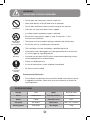
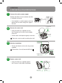
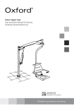
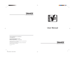
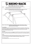
USER MANUAL
www.sterillo.com
WARNING:
INJURY MAY OCCUR IF MISUSED
• Do not open the front panel – electric shock risk
Never look directly at the UV bulb when in operation
• Prohibited
Do not allow children or adults to pull or hang on the machine
• Place the unit away from direct water supplies
• A suitably rated fused power supply is required
• Ensure the correct power supply is used, if more than +/-10%
• the unit may malfunction
Do not allow
unit to get
excessively wet
The power must be turned off during installation and maintenance
• Ensure the unit has a reliable earth connection
• This hand dryer must be installed by a qualified electrician
• Do not
dismantle
If the power cord is damaged it must be replaced by the manufacturer,
• its service agent or a qualified person
A residual current device (RCD) with a rated residual operating current,
• not exceeding 30mA is recommended
Please use dedicated spur
• In case of malfunction, switch off power immediately
• Follow
instructions
carefully
Air filter must be installed
• Environmental Protection
• Do not dispose of electrical waste with household waste, please recycle
in appropriate facilities. Check with your Local Authority or retailer for
recycling advice.
SPECIFICATIONS
Voltage
240V
Motor
Brushed motor
Phase
Single phase
Sensing distance
15–20cm
Power
1400W
Protection class
IPX1
Air speed
60–105m/s
Dimensions
335 x 172 x 410mm
Heating power
800–950W
Net weight
5.1kg
2
LOCATION
& PRE-INSTALLATION PRECAUTIONS
DO NOT install in the following places
•Where the temperature can be below -10°C or above 40°C
•Where the unit may come into direct contact with excessive water
• If the unit will be in direct or strong sunlight
•If there is a lot of condensation in the environment
•If there are corrosive, neutral or reductive gases present
•20m or more below, or 2000m or higher than, sea level
Installation position
The following diagram shows the recommended position
•
Ensure there is at least 150mm clear space below the machine
(either to the floor or other objects in the location)
•
It is recommended that a minimum distance of 100mm should
be left clear to either side of the unit
•
Avoid locations where people or doors might damage the unit
•
Choose a completely flat wall surface to mount the unit onto
241mm
241mm
Floor
3
258mm
190mm
160cm
240mm
258mm
Hole of junction box
without shell
170cm
(4-7)
81cm
(7-10)
91cm
(10-13)
102cm
(13-16)
112cm
LOCATION
& PRE-INSTALLATION PRECAUTIONS
1
Connect the unit to power supply
Embed a backbox in the installation location
(1 switchbox no cover)
Power
supply
cable
1060mm
•If no backbox is used the power cord may
prevent the unit from sitting flush against
the wall
2
m
0m
30
Countersunk
screws
Remove the outer shell
•
Using the Allen key supplied, remove
the 2 countersunk screws from the body
of the unit
Allen key
Shell
• Pull the outer shell upwards gently to remove
UV bulb
casing
Take extra care to avoid scratching the shell
3
UV bulb
casing
Machine installation
•
Fix the unit directly to the wall using screws
supplied
Connections: Live=L, Neutral=N, Earth=
Connector
Pop out for rear
cable access
4
Replace outer shell
Shell
•
Using the Allen key supplied, tighten
the 2 screws at the sides of the body
Allen key
4
Countersunk
screws
DAILY USE
& ROUTINE MAINTENANCE
1
Place hands,
palms down,
beneath the dryer
Turn hands,
to palms up
and repeat
backwards and
forwards motion
Move backwards
and forwards in
the air flow
2
External maintenance
Finally rub
hands together
to remove any
final dampness
Sanitisation outlet
Clean with a soft cloth. If the unit is very dirty use a soft,
dampened cloth with a neutral cleaning agent, then polish
with a soft, dry cloth
•Only use neutral cleaning agents
•Do not use thinners, acidic or alkaline toilet cleaners
or nylon brushes (they may damage the surface)
•If using chemical cloths, read instructions first
3
Sensing
device
Bi-annual replacement of UV lamps
NEVER
look at the bulbs when in operation
•Ensure unit and power are switched off and
remove the outer shell to access the lamp unit
•Remove lamp unit cover to reveal the dual bulb.
Carefully clear the unit of any dust using a soft brush
•Gently loosen the old lamp by holding the lamp
holder in one hand and pulling the lamp upwards
and away from the lamp holder
•Replace the dual lamp with a new one by
inserting it into the lamp holder and pushing
it downwards until it clicks into position.
Do not touch the new lamp with your bare hands
•Replace the cover
4
LED indicator lights
•LED lights showing through the top grills slowly fade on and off under normal
operation. If the LEDs change to red, it means the lamp has failed and needs
immediate replacement, the Sterillo will still operate as a normal hand dryer,
however, its sanitisation module will not be functioning until the lamp is replaced.
5
COMPONENTS
& ELECTRICAL SCHEMATIC
1
Components
Baseplate
Shell
UV bulb
casing
Countersunk
screws
Earth
Allen key
Motor
PCB
Heater
2
Air
Outlet
UV bulb
casing
Inductor
Electrical Schematic
Fuse
Power switch
L
Power
Indicator
N
Temperature
probe
Sensing
probe
Control
relay
Brushed
motor
Heater
Heat switch
Thermal fuse
6
Temperature
switches
PACKING LIST
A.Rawplug . . . . . . . . . . . . . . . . . . . . . . . . . . . . . . . . . . . . . . . . . . . . . . . . . . . . . . . . . x 8
B. 30mm Wall screws. . . . . . . . . . . . . . . . . . . . . . . . . . . . . . . . . . . . . . . . . . . . . . . . . . x 8
C. Splashback panel . . . . . . . . . . . . . . . . . . . . . . . . . . . . . . . . . . . . . . . . . . . . . . . . . . x 1
D. Wall sticker. . . . . . . . . . . . . . . . . . . . . . . . . . . . . . . . . . . . . . . . . . . . . . . . . . . . . . . . x 1
E. Instruction manual . . . . . . . . . . . . . . . . . . . . . . . . . . . . . . . . . . . . . . . . . . . . . . . . . x 1
F. Wall fixing template (double sided). . . . . . . . . . . . . . . . . . . . . . . . . . . . . . . . . . . . x 1
G. Allen key. . . . . . . . . . . . . . . . . . . . . . . . . . . . . . . . . . . . . . . . . . . . . . . . . . . . . . . . . . x 1
H. Sterillo unit. . . . . . . . . . . . . . . . . . . . . . . . . . . . . . . . . . . . . . . . . . . . . . . . . . . . . . . . x 1
I. Warranty card . . . . . . . . . . . . . . . . . . . . . . . . . . . . . . . . . . . . . . . . . . . . . . . . . . . . . x 1
7
www.sterillo.com