1
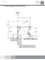
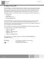
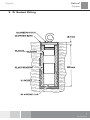
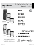
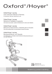
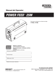
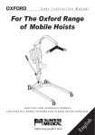
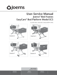
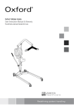
Oxford
®
Oxford Dipper Hoist
User Instruction Manual & Warranty
®
To avoid injury, read user manual prior to use.
Redefining patient handling
English
Oxford
Dipper
®
Manufacturer’s Contact Details
Oxford
®
EuropE
Joerns Healthcare Ltd
High Street, Wollaston, Stourbridge,
West Midlands DY8 4PS
ENGLAND
+44 (0)1384 44 66 22
Fax: +44 (0)1384 44 66 01
www.joerns.co.uk
Contents
1. Oxford Dipper Lift Illustration.........................................................................................................3
2. About Your Lift................................................................................................................................4
3. “A” Socket Fitting...........................................................................................................................5
4. Installation of the Oxford Dipper Base Socket...............................................................................6
5. “B & C” Socket Illustration..............................................................................................................7
6. Assembly and Commissioning Instructions....................................................................................8
7. Fitting a Ranger Chair to a Dipper Lift............................................................................................9
8. Safety Precautions.......................................................................................................................10
9. Operating Instructions.................................................................................................................. 11
10. Daily Check List...........................................................................................................................12
11. Maintenance Schedule................................................................................................................13
12. Technical Specifications...............................................................................................................14
13. Slings For Use with the Oxford Dipper Lift...................................................................................15
14. Servicing, Repairs, Inspections & Testing....................................................................................16
374-10045 Rev A
English
Oxford
Dipper
®
1. Oxford Dipper Lift Illustration
374-10045 Rev A
English
Oxford
Dipper
®
2. About Your Lift
The Oxford Dipper is a hydraulically operated patient lift intended for use in swimming pools and similar
facilities. The Dipper has a seat or a sling option. Each lift is fully assembled, load tested and certified
before being partially dismantled for packing. The packing consists of a strong, purpose built carton
and is used for both export and domestic markets to ensure the safe arrival of the lift. A number of
documents are supplied in a wallet packed with each lift and should be kept safely for future reference.
•
•
•
•
Test Certificate
User Manual
Dealer Guarantee Card
Customer Satisfaction Card
The TEST CERTIFICATE is an important document and will be required for your insurance records.
It is valid for six months and after it has expired the lift should be inspected and serviced for the
following six months. Servicing and periodic testing can be carried out by your supplier. Please ensure
your lift is included in their maintenance schedule.
The Oxford Dipper Lift is suitable for the following CATEGORIES of lift within the working parameters
of the Dipper specified in the TECHNICAL SPECIFICATIONS.
•
•
•
•
•
Category A - Wheelchair
Category C - Bath
Category D - Toilet/Shower Chair
Category E - Floor
Category F - 90 Degree Rotation
The Oxford Dipper Lift is suitable for patients in the SITTING, SITTING/RECUMBENT and
RECUMBENT positions.
The CE mark:
374-10045 Rev A
The Oxford Dipper Lift carries the CE mark and complies
with the following EC directive:
• Medical Device Directive (93/42/EEC)
English
Oxford
Dipper
®
3. ‘A’ Socket Fitting
374-10045 Rev A
Oxford
Dipper
®
English
4. Installation of the Oxford Dipper Base Socket
The base socket of the Dipper is subjected to high loading during use. It is essential the immediate
area around the socket is a good sound concrete construction able to withstand the substantial side
force imposed. Joerns Healthcare Ltd strongly recommend an architect is consulted for all applications.
All installations should be tested to the manufacturers recommendations prior to hand over to the
users, with particular attention being paid to the socket and surrounding concrete.
There are three types of socket available. These are designated “A”, “B” & “C” sockets and will
enable the Dipper to be fitted alongside the majority of swimming pools. Special applications such
as hydrotherapy pools or boat mooring pontoons should be discussed with your local dealer or with
Sunrise Medical direct.
1. “A” Socket Fixing
This is the most commonly supplied socket and is fitted into a hole 90 mm diameter, core bored into
the concrete slab to a depth of 245 mm. The socket is held firmly in place with a non shrinking cement.
The construction of the “A” socket is shown on page 5. When correctly fitted the top of the socket is 12
mm below the floor level. Each socket is supplied with a blanking plug to prevent ingress of water when
the mast has been removed for storage. When fitted the top of the blanking plug is flush with the floor
level.
2. “B” Socket Fixing
This socket is for use on swimming pools with a water channel around the edge of the pool. Basically
the “B” socket is an “A” socket with a plate which adds additional bracing. The “B” socket plate is fixed
in place with six 15 mm diameter expanding bolts of the Rawplug type. The “B” socket construction is
illustrated on page 7. As with the “A” socket the “B” socket is slightly below floor level and is fitted with
a blanking plug.
3. “C” Socket Fixing
This socket is surface mounted and stands proud of the floor by 150 mm. It is used mainly where there
is insufficient depth of concrete for “A” or “B” sockets. The “C” socket plate is drilled for four 15 mm
Rawplug type expanding bolts. The recommended minimum depth of concrete for the “C” socket is 150 mm.
The “C” socket adds 150 mm to the height of the mast. This alters the maximum height of the bottom
of the chair (to 1039 mm) and the lowest position of the chair bottom below floor level (to 764 mm). An
illustration of the “C” socket is shown on page 7.
374-10045 Rev A
English
Oxford
Dipper
®
5. “B and C” Scoket Illustration
374-10045 Rev A
Oxford
Dipper
®
English
6. Assembly and Commissioning Instructions
Place the carton in a clear working area and open carefully. The carton contains:
•
•
•
•
•
•
Mast & Hydraulic Unit Assembly
Boom Assembly
Chair Support Tube (Seat Option)
Spreader Bar Assembly (Seat Option)
“A” Or “B” Socket
Wallet Containing Documents
and in separate cartons:
• Transporter seat & chassis (seat option)
• “C” socket
1.
Remove the “A”, “B” or “C” socket from the carton and install according to the instructions in the Installation of the Dipper base socket on page 6 of this manual.
SAFETY NOTE: The socket is heavy and will need to be lifted with care. You may need assistance with lifting.
2. After the socket is correctly installed remove the rest of the parts from the carton taking care to protect the finish from damage.
3.
Insert the spigot at the base of the mast into the floor socket. The spigot will displace any water in the socket so caution should be exercised to avoid splashing.
SAFETY NOTE: Avoid trapping fingers. Keep fingers away from the end of the mast spigot when inserting into the socket.
4. Fully unwind the “T” shaped clamp screw at the top of the mast. The travel of the screw is limited by a fixed stop. Keep turning until the stop is encountered. DO NOT force the screw past the stop.
5. Assemble the boom to the mast. Engage the boom and tie rod pivots in the locating hooks at the top of the mast.
6. Still holding the boom in place, insert the boom ram spigot into the top of the hydraulic ram. The boom can now be released.
7. Rewind the “T” shaped clamp screw and tighten fully.
8.
Close the hydraulic unit release valve by turning the knurled black knob on the unit fully clockwise.
NOTE: The release valve requires only minimal tightening to operate and should only be closed finger tight. DO NOT apply excessive force to the valve knob as this will result in damage to the valve.
9. Pump the handle of the hydraulic unit and confirm the ram raises the boom.
10. Open the release valve fully anticlockwise and check the boom descends.
374-10045 Rev A
English
Oxford
Dipper
®
11. Close the release valve and raise the boom until it is approximately parallel to the floor.
12. Fully unwind the small “T” shaped clamp screw at the extreme end of the boom. Like the mast clamp the travel on this screw is limited by a fixed stop. Keep turning until the stop is encountered. DO NOT force the screw past the stop.
13. If the lift is a seat option version, the curved chair support arm can now be assembled to the boom. Pass the support arm end through the bearing tube at the end of the boom, making sure the safety latch at the top of the tube engages in the grooved end of the chair support arm. The support arm will now be held and can be rotated through 360 degrees. The “T” shaped clamp screw, when tightened, will prevent rotation.
14. If a spreader bar and slings are to be used instead of a chair, the Spreader bar assembly is fitted in place of the chair support tube.
Pass the spreader bar pivot tube through the bearing tube at the end of the boom, making sure the safety latch at the top of the tube engages in the grooved end of the spreader bar pivot tube. The spreader bar assembly will now be held and can be rotated through 360 degrees. The “T” shaped clamp screw, if tightened, will have no effect on spreader bar rotation.
15. The lift is now ready for the Ranger chair or sling attachment.
7. Fitting A Ranger Chair To A Dipper Lift
The Ranger chair is made in two assemblies, the wheeled chassis and the seat with armrests. The halves
of the complete chair are connected with a simple latch located at the rear of the seat. The chair is attached
to the bath lift as follows:
1. The chair support arm of the lift has a hook and latch device similar to the one connecting the Ranger seat to the chassis. The support arm hook must be engaged with the cross bar at the top of the Ranger seat. The latch will engage automatically and prevent accidental disengagement.
2. The seat can now be lifted off the chassis by operating the seat latch, which holds the seat to the chassis, and raising the boom of the lift with the hydraulic unit. The seat will be elevated with the boom and the chassis will remain behind.
3.
To reconnect the seat to the transporter, lower the seat onto the chassis with the lower safety latch in approximately the right position. The seat will lock automatically as the seat is lowered. When the seat latch is engaged, disengaged the latch on the chair support arm and continue to lower the boom. The support arm will drop away from the seat and can be swung away to one side. Check full engagement of the seat latch. The patient can now be transported to another location.
374-10045 Rev A
Oxford
Dipper
®
English
8. Safety Precautions
Please read and follow the safety precautions listed below. The operation and use of Oxford patient lifts
is simple and straightforward. Following these few basic safety precautions will make lifting operations
easy and trouble free.
• ALWAYS plan your lifting operations before commencing.
• ALWAYS carry out the DAILY CHECK LIST before using the lift.
• ALWAYS familiarise yourself with the operating control and safety features of a lift before lifting a patient.
• DO NOT use a sling unless it is recommended for use with the lift.
• ALWAYS check the sling is suitable for the particular patient and is of the correct size and
capacity.
• NEVER use a sling which is frayed or damaged.
• ALWAYS fit the sling according to the instructions provided (user instructions).
• ALWAYS check the safe working load of the lift is suitable for the weight of the patient.
• ALWAYS carry out lifting operations according to the instructions in the user manual.
• NEVER disconnect or bypass a control or safety feature because it seems easier to operate the lift.
• NEVER force an operating or safety control. All controls are easy to use and do not require excessive force to operate. If a control is not working easily there will be a reason. Forcing will only strain or damage the lift and may compromise safety.
• DO NOT lift a patient unless you are trained and competent to do so.
• Your lift is for patient lifting. DO NOT use it, or allow it to be used, for any other purpose.
10
374-10045 Rev A
English
Oxford
Dipper
®
9. Operating Instructions
1. First check the Dipper is assembled according to the instructions in the Assembly and Commissioning section.
2. Connect the Ranger chair to the seat support arm on the lift.
3. Make sure the hydraulic unit release valve is fully closed (fully clockwise - finger tight).
Note: The raising and lowering of the boom is achieved by a powerful hydraulic ram which is operated by two simple controls. The release valve, which is identified by a black knurled knob, and the pump handle which is a long lever on the side of the hydraulic unit.
To raise the boom, ensure the release valve is closed. The valve is closed by gently turning the knurled knob fully clockwise. When closed, pump the long handle with smooth even strokes for maximum effect. The handle strokes from an upright position through an arc of 90 degrees. Leave the handle in the upright position when not in use.
DO NOT force the handle beyond the upper or lower stops.
The hydraulic unit can be rotated to allow the handle to be used from either side of the lift.
To lower the boom, turn the release valve anticlockwise. The release valve is progressive, the more it is opened the faster the descent. The valve is restricted so even when fully open the descent is controlled. This facility allows for a “hands free” descent. If the release valve is opened a fraction (a quarter turn) a very slow speed of descent will allow the carer to work “hands free” while assisting or comforting the patient.
REMEMBER to close the release valve before commencing lifting operations. The release valve only requires gentle pressure to open or close. DO NOT apply excessiveforce to the release valve, either to close or to open. It is not necessary and will only damage the valve.
4. Release the seat latch and raise the boom slowly by pumping the hydraulic unit handle. This will lift the seat away from the chassis.
5. When the seat is clear of the chassis, stop pumping and swing the boom and seat over the water.
6. Lower the seat into the water by turning the hydraulic unit release valve anticlockwise.
7. To raise the seat, turn the release valve until closed and then pump the hydraulic unit handle.
8. Swing the boom back from the water, position the seat over the Ranger chassis and lower the seat until the chair is reconnected.
9. Release the latch from the chair support arm. The ranger can now be wheeled away.
10. Slings: The selected sling is attached to the spreader bar hooks, each sling is supplied with instructions and they are reproduced in this manual. The instructions should be followed carefully. The operation of the hoist is the same for the chair and sling options. Use only Oxford slings from the Quickfit, Full Back, Quickfit Deluxe and Longseat range.
11
374-10045 Rev A
Oxford
Dipper
®
English
10. Daily Check List
All Oxford products are designed for minimum maintenance, however some safety checks and
procedures are required. A schedule of DAILY tasks are detailed below. Daily checks and a biannual
service, inspection and test will ensure a lift is kept in optimum safe working condition. A list of spare
parts is available upon request. The LOAD TEST and CERTIFICATION should only be carried out by
qualified personnel or an authorised service dealer.
DAILY CHECK LIST
Joerns Healthcare Ltd strongly recommend the following checks are carried out on a daily basis and
before using the lift.
• MAKE sure the mast is fully located in the floor socket and is free to rotate.
• MAKE sure the spreader bar, if fitted, is free to rotate.
• CHECK the spreader bar or chair support tube is firmly attached to the boom and the safety latch
holding the spreader bar or chair tube to the boom is engaged and working correctly.
• EXAMINE the sling hooks on the spreader bar and side suspenders for excessive wear. If in
doubt - do not use.
• CHECK the safety latch which connects the chair to the chair support tube. Make sure the chair is
fully engaged and the latch prevents accidental disengagement.
• OPERATE the hydraulic unit to confirm the boom raises and lowers satisfactorily.
• CHECK the chair for correct engagement of the seat to the chassis.
• CHECK for hydraulic fluid leakage. Any leakage should be reported to service engineer immediately
and the lift should not be used until it has been checked out.
• EXAMINE slings for fraying or other damage. DO NOT use any sling if damaged or if the sling
shows signs of wear.
12
374-10045 Rev A
English
Oxford
Dipper
®
11. Maintenance Schedule
Joerns Healthcare Ltd recommend a thorough inspection and test of the Oxford Dipper and lifting
accessories, slings etc. is carried out every six months. The examination and test should be conducted
according to the recommendations and procedures below. Joerns Healthcare Ltd recommend
maintenance, inspection and certified testing is carried out by authorised service dealers only.
Note: These recommendations are in compliance with the requirements of 1998 No 2307 Health and Safety:
The Lifting Operations and Lifting Equipment Regulations 1998.
This is a UK regulation. Outside the UK please check your local requirements.
• SPREADER BAR: Check the spreader bar for freedom of rotation. Check for wear on the central pivot. Check the attachment to the boom and the operation of the safety latch. Inspect for excessive wear on the sling hooks and any side suspenders used in conjunction with the spreader bar.
•
BOOM: Check the attachment of the boom to the mast. Make sure the mast clamp screw can be fully tightened and prevents disconnection of the boom from the mast. Check the boom raising and lowering is smooth and unhindered. Lubricate all pivot points as necessary with a light mineral based grease. Check for full engagement of the boom ram pin with the hydraulic ram top. Make sure the boom ram pin is free to pivot on the mounting brackets. Lubricate if necessary.
•
CHAIR SUPPORT TUBE: Confirm the chair support tube is free to rotate but can be prevented from rotating by tightening the support tube clamp screw. Confirm correct operation of the safety latch connecting the tube to the boom. Lubricate pivots as necessary. Check the function of the chair retaining latch and ensure the latch pivot is free and lubricated.
• CASTORS: Check all castors for firm attachment to the chair legs. Check for free rotation of the castor and the wheels. Remove any build up of threads, hair or fluff. Lubricate if necessary with a light mineral based grease. Check correct operation of the brakes.
• HYDRAULIC UNIT: The hydraulic unit should require no maintenance other than checking for correct operation and leakage of hydraulic fluid.
• MAST: Check the mast rotates freely in the floor socket. Lubricate with a light mineral based grease as necessary. Check the mounting of the hydraulic unit to the mast, make sure the hydraulic unit pivots freely. Lubricate if necessary.
• GENERAL: Check all nuts and bolts for tightness. Tighten if necessary.
• CLEANING: Clean with ordinary soap and water and/or any hard surface disinfectant. Harsh chemical cleaners or abrasives should be avoided as these may damage the surface finish of the lift.
• LOAD TEST: The load test should be carried out in accordance with the manufacturers test procedures. It is strongly recommended the testing is carried out by an authorised service dealer.
• CERTIFICATION: An authorised service dealer will issue a test certificate after satisfactory completion of the load test. This certificate will be valid for six months.Met velit nonum do ectet, quamet lamconsed tat am nis ero commod molor amcon hent vendre feumsan hendre vercin
13
374-10045 Rev A
English
Oxford
Dipper
®
12. Technical Specifications
Safe Working Load
140kgs
Boom Length
1498mm
“A” & “B” SOCKET:
Height (Boom Lowered)
1422mm
Height (Boom Full Elevation)
2108mm
Base of Seat Above Floor Level
889mm
Base of Seat Above Floor Level
914mm
“C” SOCKET:
Height (Boom Lowered)
1572mm
Height (Boom Full Elevation)
2258mm
Base of Seat Above Floor Level
1039mm
Base of Seat Below Floor Level
764mm
WEIGHTS:
Mast Assembly
15.4 Kgs
Boom Assembly
10.4 Kgs
Chair Support Tube
3.6 Kgs
Ranger Seat
4.5 Kgs
Ranger Chassis
8.7 Kgs
Spreader Bar Assembly
1.7 Kgs
MATERIALS:
Stainless Steel
Galvanised and Plastic Coated Steel
14
374-10045 Rev A
English
Oxford
Dipper
®
13. Slings For Use with the Oxford Dipper Lift
Joerns Healthcare Ltd range of Polyester net slings can be used with the Oxford Dipper Lift.
The slings suitable for this device are listed as follows:
•
•
•
•
Oxford Quickfit Sling
Oxford Full Back Sling
Oxford Quickfit Deluxe Sling
Oxford Longseat Sling
Special requirement slings can be made to customers own specification, consult your dealer for details.
NOTE: For detailed fitting instructions, please refer to the user guide supplied with each sling.
WARNING
Joerns Healthcare recommends that slings be checked regularly and particularly before use for
signs of fraying or damage. DO NOT use slings that are worn or damaged.
WARNING
OXFORD RECOMMENDS THE USE OF GENUINE OXFORD PARTS. Oxford sling and lift products
are designed to be compatible with one another. For country specific guidance on sling use and
compatibility, please refer to the sling label or contact your local market distributor or Joerns
Healthcare.
WARNING
Refer to maximum weight capacity of lift. Sling capacity is limited by the maximum capacity of
the lift.
15
374-10045 Rev A
Oxford
Dipper
®
English
14. Servicing, Repairs, Inspections and Testing
Joerns Healthcare Ltd has an established network of reputable distributors and dealers who will be
pleased to handle all your purchasing, warranty, repair and maintenance enquires.
Included with each lift is a prepaid Customer Satisfaction card. Please take the time to fill it in and return
it to Joerns Healthcare Ltd. Our products are guaranteed for a period of twelve months from the date of
manufacture or twelve months from the date of purchase if commissioned by an authorised dealer. We
recommend that all of our products are commissioned by your dealer and are supported by them for
future servicing.
The dealer or distributor operates the warranty programme, so it is important to keep a record of their
name address and telephone number so they can be contacted should any problem arise.
If you are in doubt where your lift was purchased, Joerns Healthcare Ltd can trace the supplier if you
quote the serial number of the lift.
REMEMBER: Contact your distributor for purchases, Warranty, repairs, servicing and certified
maintenance.
Your distributor:
16
374-10045 Rev A
English
Oxford
Dipper
®
17
374-10045 Rev A
Joerns Healthcare Ltd
High Street, Wollaston
Stourbridge, West Midlands
DY8 4PS
ENGLAND
Tel: +44 (0)1384 44 66 22
Fax: +44 (0)1384 44 66 01
www.joerns.co.uk
© 2008, Joerns Healthcare
374-10045 Rev A