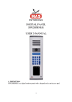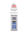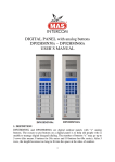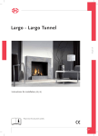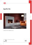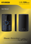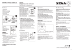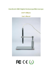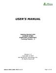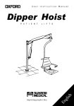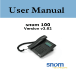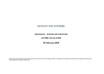
1
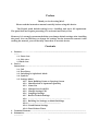
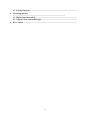
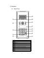
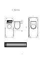
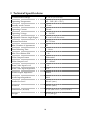
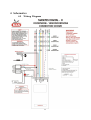
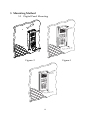
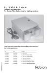
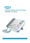
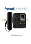
MAS DIGITAL PANEL USER’S MANUAL
1
2
3
C
4
5
6
GÖREVLİ
7
8
9
0
ARA
DP02HM / DP01HM
1
Preface
Thank you for choosing MAS
Please read the instruction manual carefully before using this device.
The Digital panel default setting is for 1 building and up to 255 apartments.
The panel does not require presetting. It is activated and ready to use.
However, it is strongly recommended that you change default settings after installing
the panel. You can find how to change the settings on the instruction manual. After
reading the manual, you will be fully aware how to use this device.
Contents
1. Features…………………...........................................................................................................
..........
1.1 Front view
1.2 Side view
1.3 Back view
2. Device
Instructions……………………………….......................................................................
2.1 Call
2.2 Door Entry
2.3 Switching to Alphabetic Mode
2.4 Symbols
2.5 Settings Menu
2.5.1 Enter Building Name on Opening Screen
2.5.2 Identification of Apartment Quantity
2.5.3 Name List
2.5.4 Change Door Lock PIN
2.5.5 Change Settings PIN
2.5.6 Language Settings
2.5.7 Back to Default Settings
2.5.8 …………………………………………………………
2.5.9 Building No Settings on Multi-Buildings
2.5.10 ...................................................................
2.5.11 Guard Button Settings
2.5.12 Door Release Timer
3. Technical Features…...............................................................................................................
4. Schematics…………………………………..............................................................................
..................
2
4.1. Wiring Diagram............................................................................................................
5. Mounting Method
......................................................................................................................
5.1. Digital Panel Mounting ............................................................................................
5.2 . Digital Panel Standard Height ................................................................................
6. Box Content .........................................................................................................................
3
1. Features
1.1
Front View
13
11
12
9
10
8
1
2
3
C
4
5
6
GÖREVLİ
7
8
9
6
7
5
4
0
3
ARA
2
1
1
Microphone
2
3
4
Up button
Down button
Call button
5
6
7
8
9
10
Guard button
“C” Clear button
PIN pad
LCD display.
Night view IR LED’s to enhance image quality
Camera
11
12
13
Light Sensor (Photocell)
Motion Sensor
Speaker
4
1.2
Side View
2.3”
0.8”
5
1.3
Back View
4.3”
110
3
1
1
Pan and tilt the camera within 32° angles to adjust
2
Connector cover
3
Screw Terminal Block Connector
6
271
10.7”
2
2. Device Instructions
2.1 CALL
In standby mode push any button, enter the apartment number and then push the CALL
button. If you do not know the apartment number, find the name of the resident via searching the
UP, DOWN buttons. Then, press the CALL. To call guard, press the GUARD button.
2.2 DOOR ENTRY
A set of four numbers called as PIN. Each apartment has its own PIN or apartments have
shared PIN to open the building entrance. (For your safety do not share your PIN with others.)
In standby mode push the C button until the words “Enter Your PIN” are displayed and
enter the four digits door release PIN within 12 seconds. Otherwise the system will resume to
standby mode. (Note: The default PIN is 1234) The PIN would not appear in the screen, for that
reason enter the PIN carefully. If there is a mistake, reset the PIN by pressing the C button and
enter the PIN again or enter the rest of the digits to complete the set to four digits then you can
enter again.
2.3 USE OF THE BUTTONS IN ABC MODE
In ABC mode; to type the requested letter, press relevant button:
To choose first letter, press once
To choose second letter, press twice
To choose third letter press, three times
EXAMPLES: To display "C" press the #2 three times, to display “K”, press the #5 three times
quickly. This method is called single key mode with many options.
NOTE: When you press another button cursor moves to next digit. To move onto right cell on the
display or to be able to enter the same letter again wait for few seconds after entering the first
letter. For more information about the characters, you can use table on menu 2.4.
2.4 SYMBOLS
BUTTON
1
2
3
4
5
6
7
8
9
0
DISPLAYED
.,-?!'@:1
ABC2
DEF3
GHI4
JKL5
MNO6
PQRS7
TUV8
WXYZ9
0
7
NOTE: To leave space press “0” for once.
2.5ENTERING MENU SETTINGS
In standby mode push any button and see the menu to enter apartment number. Enter any
apartment number, press the “C” button continuously till the words “Settings PIN” are displayed
then you can enter settings PIN and make the necessary changes. The default PIN is “0000”. (It is
strongly recommended to change “Settings PIN” and store it carefully.) If you don not press any
button within 6 seconds, panel switches to standby mode then need to re-enter Settings Menu.
You can press the numbers “1 to 9” to enter sub-menus on “Menu Settings”. By using the
UP and DOWN buttons you can select sub-menus.
2.5.1. ENTERING BUILDING NAME ON OPENING SCREEN
Opening Screen menu is #1 on Settings Menu. As optional building name or Welcoming
message is typed. (Example: “Welcome to xXx Building”) To enter the menu, enter menu
settings first, press “1” then press CALL. Type your message in Line1 then press the CALL to
type in Line 2. If you want to leave the Line 2 blank just press the CALL after entering Line 1
Message. Each line has 16 digits to use.
2.5.2. IDENTIFICATION OF APARTMENT (APARTMENT) QUANTITY (IFQ)
IFQ menu is #2 on Settings Menu. This menu limits the panel on use of the apartment
quantity. To enter the menu, enter menu settings first, press “2” then press CALL, type total
apartment quantity and press CALL to save it.
NOTE: Apartment quantity can be maximum 255. Please pay attention not to leave quantity “0”.
when you enter IFQ menu.
2.5.3. NAME LIST
Name List menu is #3 on Settings Menu. It is possible to display who the resident at
referred apartment number is. Visitors can browse the residents via the UP, DOWN buttons then
press the CALL to call the required apartment. To edit the name list menu, enter settings menu,
press 3 then the CALL. Type apartment number, then press CALL to edit the apartment. Type
resident “name-surname”, then press CALL to save the information.
2.5.4. CHANGING DOOR PIN
Changing Door Pin menu is #4 on Settings Menu. This menu is to change the door
opening pin. Enter settings menu, press 4 then CALL. Enter quantity of PIN numbers (1 to 100)
then enter PIN numbers for each apartment. The default door release PIN is “1234” Quantity of
PIN numbers should be entered as defined otherwise default Door PIN would remain.
2.5.5. CHANGING SETTINGS PIN
Changing Settings Pin menu is #5 on Settings Menu. This menu is to change the Settings
PIN. Enter settings menu, press 5 then the CALL and the CALL again, “Settings PIN” appears on
the screen to enter four digits “New PIN”. Press the 1CALL to save the new PIN. Default
Settings PIN is “0000”.
2.5.6. LANGUAGE OPTIONS
Language Options menu is #6 on Settings Menu. This menu is to set panel language.
Enter settings menu, press 6 then the CALL. Press 1,2,3,4 to select your language then press the
CALL to set it. Language options below.
1-English,
8
2-Spanish,
2.5.7. BACK TO DEFAULT SETTINGS
Back to Default Settings menu is #7 on Settings Menu. This menu is to reset current
settings and it restores manufacturer settings. Enter settings menu then press 7 then CALL,
“BACK TO DEFAULT SETTINGS?” appears on the screen, if you press CALL panel would
start counting from 1 to 260 then returns to standby mode screen and panel is set to default
settings. When “BACK TO DEFAULT SETTINGS” appeared on screen, if you press the C the
panel would not clear existing information and return to Settings Menu.
2.5.9. BUILDING NO SETTINGS ON MULTI-BUILDINGS
Building No Settings on Multi-Buildings menu is #9 on Settings Menu. This menu is to
set building number. Enter settings menu then press 9 then the CALL, enter building number then
CALL.
Attention! For Multi-Building Systems, if you don not set building number or leave “0”
when an apartment is called, system would call the same numbered apartments in all
buildings.
2.5.11. OPTIONAL BUTTON ( GUARD BUTTON )
Optional Button menu is #11 on Settings Menu. This menu is to set to call guard’s station
directly without entering apartment number. You can enter any apartment number to call directly,
default Guard Station number is 255.
NOTE: Pay attention NOT TO press the CALL without entering apartment number,
Guard Apartment would be set as “0”.
2.5.12. DOOR RELEASE TIMER
Optional Button menu is #12 on Settings Menu. This menu is to set to door releasing time.
Enter settings menu, press 12 then CALL. Use the UP / DOWN buttons to set the required
releasing time then press the CALL to set it. ( D.R.T. range is up to 10 secs. )
9
3 Technical Specifications
Communication Range
28 ± 4 in. (70 ± 10 cm)
Operating Temperature
-4F…130F (-20⁰...+55⁰C)
Standby mode Current
115 mA
Operating Current
150 mA
Operating Voltage
16…24 VDC
Adjustable Camera Angle Degree
32⁰ total in all directions
Camera Resolution
350 TV lines
Max. Number of Apartments
255
Door Releasing Time
1…10 sec
Max. Door Release PIN
1...99
Video Output Format
Differential
Video Output Level
2V… 800mV
Extra Video Input Level
1,1 V
Extra Video Input Impedance
75 Ω
Audio Output Impedance
1200 Ω
Audio Input Impedance
600 Ω
Audio Out Level
600 mV (max.)
Audio In
600 mV (max.)
Dimensions ( W/H/D)
10.7/4.3/0.8-2.3 in. ( 27/11/2-6 cm )
Weight
23 oz. (645 gr)
10
4 Schematics
4.5 Wiring Diagram
11
5 Mounting Method
5.5 Digital Panel Mounting
Figure: 2
Figure:1
12
Figure:3
Remove top and bottom plastic ledges as seen in Figure: 1.
Drill the holes and place the rawplugs as seen in Figure: 2.
Mount the panel on the wall from the screw holes then place the plastic ledges as seen in
Figure:3
5.6 Digital Panel Standard Height
Mount the digital panel to a proper place away from hazards (water, dust, chemicals &
etc.) and away from direct light sources (sun, street lights, white or transparent
backgrounds). *Suggested mounting height: 5’- 5’2” (Camera lens to ground, Eye-level,
160-165cm)
If required use a top cover.
Attention : Mount the digital panel to a proper place away from direct light and rain.
FCC STATEMENT
This equipment has been tested and found to comply with the limits for a Class B digital
device, pursuant to part 15 of the FCC Rules. These limits are designed to provide
reasonable protection against harmful interference in a residential installation. This
equipment generates, uses and can radiate radio frequency energy and, if not installed
and used in accordance with the instructions, may cause harmful interference to radio
communications. However, there is no guarantee that interference will not occur in a
13
particular installation. If this equipment does cause harmful interference to radio or
television reception, which can be determined by turning the equipment off and on, the
user is encouraged to try to correct the interference by one or more of the following
measures: Reorient or relocate the receiving antenna. Increase the separation between
the equipment and receiver. Connect the equipment into an outlet on a circuit different
from that to which the receiver is connected. Consult the dealer or an experienced
radio/TV technician for help.
14
6 Box Contents
Item
Quantity
Digital
Panel………………….…..…….…………………………………………………………………
………1
Connector
Protector.…….…..……………………………………………………………………………….1
Connector......................………...…….……………………………………………………………
…………….1
Screw……………………………..….….…………………………………………………………
………………..4
Rawplug....………………………....………………………………………………………………
……………....4
User’s
Manual..........………...…….…….....................................................................................................
1
15
16