1
ion
Reference Manual
This page intentionally left blank
Table Of Contents
Introduction ........................................................7
Welcome!..................................................................................................7
Unpacking and Inspection .......................................... 8
How to Use This Manual .............................................. 8
Important Safety Instructions ........................9
Important Safety Instructions (English).................. 9
Safety symbols used in this product ....................................................9
Please follow these precautions when using this product:...............9
Instructions de Sécurité Importantes
(French)............................................................................ 10
Symboles utilisés dans ce produit ........................................................10
Veuillez suivre ces précautions lors de l’utilisation de
l’appareil: ..................................................................................................10
Lesen Sie bitte die folgende
Sicherheitshinweise (German) ................................... 11
Sicherheit Symbole verwendet in diesem Produkt ............................11
Folgen Sie bitte diesen Vorkehrungen, wenn dieses
Produkt verwendet wird: .......................................................................11
CE Declaration Of Conformity ................................... 12
FCC Compliance Statement ........................................ 12
Chapter 1: Connections.....................................13
Connecting AC Power ...........................................................................13
Making Audio Connections ..................................................................13
Connecting the Foot Pedals..................................................................13
Connection Diagram..............................................................................14
Chapter 2: Overview ..........................................15
A Tour of the Front Panel............................................ 15
The display...............................................................................................15
LED functions ........................................................................................17
Button functions.....................................................................................17
All Notes Off: the [home] button........................................................18
Knob functions.......................................................................................18
Performance controls ............................................................................18
Chapter 3: Global Parameters.........................19
What does “Global” mean? ..................................................................19
The Global parameters..........................................................................19
LCD Contrast .........................................................................................19
Keyboard Curve......................................................................................19
LCD Mode ..............................................................................................19
Master Tune.............................................................................................20
Transpose.................................................................................................20
Octave ......................................................................................................20
MIDI Sync...............................................................................................20
Tempo Source .........................................................................................21
MIDI Bank Select...................................................................................21
Mod Wheel 2 CC....................................................................................21
Exp Pedal CC..........................................................................................21
Exp Pedal Curve.....................................................................................22
Arp Send MIDI ......................................................................................22
1
Table Of Contents
Arp Retrigger ..........................................................................................22
Analog Drift ............................................................................................23
Last Part Enable .....................................................................................23
P/M Wheel LEDs..................................................................................23
Pgm Write Protect..................................................................................23
Chapter 4: Parts and Setups ............................25
What is a Setup?......................................................................................25
Programs vs. Parts..................................................................................25
How the Effects are Shared..................................................................25
Storing a Program or Setup ..................................................................26
Naming a Program or Setup.................................................................27
Character chart........................................................................................28
Sending a Program or Bank via Sys-Ex ..............................................29
Special cases.............................................................................................30
Sending One Setup or All Setups via Sys-Ex.....................................31
Sending All Programs and Setups via Sys-Ex ....................................32
Storing and Recalling Setups.................................................................32
Compare Mode................................................................ 33
Part Parameter Descriptions...................................... 33
Program Bank .........................................................................................33
Program ...................................................................................................33
MIDI Channel.........................................................................................34
MIDI/Local ............................................................................................34
Low Key...................................................................................................34
High Key..................................................................................................34
Out Level .................................................................................................35
Out Balance .............................................................................................35
EFX Level................................................................................................35
Pan ............................................................................................................35
Sust Pedal Enable ...................................................................................36
Exp Pedal Enable ...................................................................................36
Pitch Wheel Enable................................................................................36
Mod 1 Wheel Enable .............................................................................36
Mod 2 Wheel Enable .............................................................................37
Transpose.................................................................................................37
Octave ......................................................................................................37
Chapter 5: Program Parameters ....................39
How the Ion Makes Sound ........................................... 39
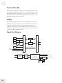
The Oscillators........................................................................................39
The Pre Filter Mix ..................................................................................39
The Filters................................................................................................39
The Post Filter Mix ................................................................................40
Output......................................................................................................40
Signal Flow Diagram..............................................................................40
Modulation ...................................................................... 41
The LFOs ................................................................................................41
The Envelopes ........................................................................................41
Program Parameter Descriptions.............................. 42
Voice: the [unison] button.....................................................................42
Voice [edit]: Unison voices....................................................................42
Voice [edit]: Unison detune...................................................................42
Voice [edit]: P Wheel mode ..................................................................43
2
Table of Contents
Voice: the [porta] button .......................................................................43
Voice [edit]: Portamento type ...............................................................43
Voice [edit]: Portamento time...............................................................44
Voice [edit]: Portamento trigger...........................................................44
Voice: the [mono/poly] button ............................................................44
LFO [edit]: Rate......................................................................................44
LFO [edit]: Sync......................................................................................45
LFO [edit]: Reset ....................................................................................45
LFO [edit]: M1 to LFOx .......................................................................46
LFO: the [1] button................................................................................46
LFO: the [2] button................................................................................46
LFO: the [s&h] button ..........................................................................46
Sample & Hold (S&H).................................................... 47
S&H [edit]: Rate......................................................................................47
S&H [edit]: Sync .....................................................................................47
S&H [edit]: Input....................................................................................47
S&H [edit]: Reset ....................................................................................49
S&H [edit]: Smoothing ..........................................................................49
Tempo ............................................................................... 49
Tempo: the [tap] button ........................................................................49
The Arpeggiator ............................................................. 50
Arp [edit]: Pattern...................................................................................50
Arp [edit]: Length ...................................................................................50
Arp [edit]: Octave Range.......................................................................50
Arp [edit]: Octave Span .........................................................................51
Arp [edit]: Note Order...........................................................................51
Arp [edit]: Tempo Multiplier ................................................................52
Arp [edit]: Program Tempo ..................................................................52
Arp: the [on] button...............................................................................52
Arp: the [latch] button ...........................................................................52
The Oscillators ............................................................... 53
Osc [edit]: Waveform.............................................................................53
Osc [edit]: Shape.....................................................................................53
Osc [edit]: Octave...................................................................................54
Osc [edit]: Pitch Semitone.....................................................................54
Osc [edit]: Pitch Fine Tune ...................................................................54
Osc [edit]: Pitch Wheel Range..............................................................55
Osc 1 [edit]: FM Level ...........................................................................55
Osc 1 [edit]: FM Type ............................................................................55
Osc 1 [edit]: FM Config ........................................................................56
Osc 1 [edit]: Sync Osc............................................................................56
Osc 1 [edit]: Sync Type ..........................................................................56
Osc 1: the [osc sync] button .................................................................57
The Pre Filter section ................................................... 57
Pre Filter Mix [edit]: Osc 1 Level.........................................................57
Pre Filter Mix [edit]: Osc 2 Level.........................................................57
Pre Filter Mix [edit]: Osc 3 Level.........................................................57
Pre Filter Mix [edit]: Ring Mod Level .................................................57
Pre Filter Mix [edit]: External Input Level .........................................58
Pre Filter Mix [edit]: Noise Level.........................................................58
Pre Filter Mix [edit]: Osc 1 Balance.....................................................58
Pre Filter Mix [edit]: Osc 2 Balance.....................................................58
Pre Filter Mix [edit]: Osc 3 Balance.....................................................59
Pre Filter Mix [edit]: Ring Mod Balance .............................................59
3
Table Of Contents
Pre Filter Mix [edit]: External Input Balance.....................................59
Pre Filter Mix [edit]: Noise Balance.....................................................59
Pre Filter Mix [edit]: Noise Type..........................................................60
Pre Filter Mix [edit]: f1 -> f2 Level .....................................................60
The Filters ....................................................................... 60
Filter [edit]: Type.....................................................................................60
Filter [edit]: Frequency...........................................................................62
Filter 2: the [offset] button....................................................................62
Filter [edit]: Resonance ..........................................................................62
Filter [edit]: Key Track...........................................................................63
Filter [edit]: Envelope Amount ............................................................63
The Post Filter Mix section ......................................... 63
Post Filter Mix [edit]: Filter 1 Level.....................................................63
Post Filter Mix [edit]: Filter 2 Level.....................................................63
Post Filter Mix [edit]: Pre Filter Level.................................................63
Post Filter Mix [edit]: Filter 1 Pan........................................................64
Post Filter Mix [edit]: Filter 2 Pan........................................................64
Post Filter Mix [edit]: Pre Filter Pan....................................................64
Post Filter Mix [edit]: Filter 1 Polarity.................................................64
Post Filter Mix [edit]: Pre Filter Signal................................................64
The Output section........................................................ 65
Output [edit]: Drive Type.....................................................................65
Output [edit]: Drive Level....................................................................65
Output [edit]: Effects Send Level .......................................................66
Output [edit]: Program Level ..............................................................66
The Envelopes ................................................................ 66
Env [edit]: Attack Time ........................................................................66
Env [edit]: Attack Slope .......................................................................67
Env [edit]: Decay Time.........................................................................67
Env [edit]: Decay Slope ........................................................................67
Env [edit]: Sustain Level.......................................................................68
Env [edit]: Sustain Time.......................................................................68
Env [edit]: Release Time.......................................................................69
Env [edit]: Release Slope ......................................................................69
Env [edit]: Keyboard Velocity Track ..................................................69
Env [edit]: Reset ....................................................................................70
Env [edit]: Freerun................................................................................70
Env [edit]: Loop ....................................................................................71
Env [edit]: Sustain Pedal.......................................................................72
Chapter 6: The Mod Matrix ..............................73
What is the Mod Matrix?.......................................................................73
Mod Matrix Parameter Descriptions ........................ 73
Mod Select ...............................................................................................73
Mod Source .............................................................................................74
Mod Destination.....................................................................................75
Mod Level................................................................................................77
Mod Offset ..............................................................................................77
Tracking Generator ...................................................... 78
Tracking Point .........................................................................................78
Level .........................................................................................................78
# of Points ..............................................................................................78
Tracking Input.........................................................................................79
4
Table of Contents
Chapter 7: Effects ...............................................81
Master Effects ................................................................. 81
Effect Type ..............................................................................................81
Effect Mix................................................................................................81
Parameters A-F .......................................................................................81
Effect Types..................................................................... 81
Bypass.......................................................................................................81
Super Phaser............................................................................................82
String Phaser ...........................................................................................83
Theta Flanger ..........................................................................................84
Thru Zero Flanger .................................................................................85
Chorus......................................................................................................86
40-Band Vocoder....................................................................................87
Chapter 8: MIDI ..................................................89
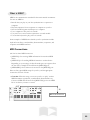
What is MIDI? ................................................................. 89
MIDI Connections.................................................................................89
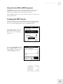
Using Your Ion With a MIDI Sequencer ...........................................91
Changing the MIDI Channel................................................................91
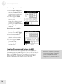
Local vs. MIDI Control.........................................................................92
Saving Programs and Setups via MIDI...............................................93
Loading Programs and Setups via MIDI............................................94
Updating Software Via MIDI...............................................................95
Sending and Receiving Bank Select Messages ...................................95
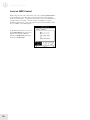
All Notes Off ..........................................................................................95
MIDI Controller Numbers ...................................................................96
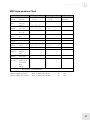
MIDI Implementation Chart................................................................97
Appendix A: Frequently Asked Questions ...99
How do I split/layer the keyboard?.....................................................99
What is a MIDI Sequence? ...................................................................99
Where can I get more Banks?...............................................................99
Are Ion Programs compatible with Andromeda
programs? ................................................................................................99
How do I change what the (m2) wheel does?....................................99
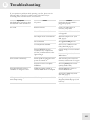
Appendix B: Troubleshooting .........................101
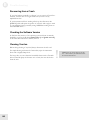
Recovering from a Crash.......................................................................102
Checking the Software Version ............................................................102
Cleaning Your Ion ..................................................................................102
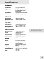
Specifications ......................................................103
Sound Engine..........................................................................................103
Audio Input .............................................................................................103
Audio Output..........................................................................................103
Audio Performance ................................................................................103
Physical.....................................................................................................103
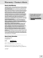
Warranty/Contact Alesis...................................105
Alesis Limited Warranty ........................................................................105
Alesis Contact Information ..................................................................105
5
Introduction
Welcome!
Congratulations on your purchase of the Ion, Alesis’s 8-voice Analog
Modeling synthesizer! It’s a powerful instrument, and we’re sure you will
find it exciting to use!
Since the dawn of digital synthesizer technology and the subsequent
decline in the number of manufacturers producing analog synthesizers,
companies have been offering an increasing number of products with
features and sounds that emulate the functional and sonic behavior of
analog synthesizers. Here at Alesis, being the company responsible for
producing the A6 Andromeda, arguably the most powerful analog
synthesizer ever released, we think we’re in the best position to produce
an analog modeling synthesizer that most closely resembles the real
thing!
Be sure to register your Ion at the Alesis website, www.alesis.com. And
since the Ion’s operating system is upgradeable via MIDI, you will want
to check the site once in a while for updates. We may well add new
features in later versions of the Ion’s software. We plan to have additional
program banks there as well, so keep checking back with us!
We hope your investment will bring you many years of creative
enjoyment and help you achieve your goals.
Sincerely,
The people of Alesis
7
Introduction
Unpacking and Inspection
The shipping carton for your Ion should contain the following items:
•
•
•
•
An Ion
AC power cable
This instruction manual
A warranty card
Please log on to the Alesis website at www.alesis.com to register your new
Ion synthesizer. This will help us give you the best support we possibly
can.
How to Use This Manual
We’re sure you’d like to jump in and start using your Ion synthesizer
quickly. To help you do this, refer to Chapter 1 for hook-up instructions,
and then read Chapter 2 “Overview.” This will get you playing in no time.
If you have any questions, refer to the Frequently Asked Questions in
Appendix A on page 99.
Basic configuration issues will be found in Chapter 3 “Global
Parameters.”
The “housekeeping” functions of the Ion, such as the process of
storing a Program, are covered in Chapter 4 “Parts and Setups.” There is
also important MIDI information regarding Setups in this chapter.
If you want to create your own sounds from the ground up or learn what
a particular knob or button does, refer to Chapters 5 through 7. Each
parameter is covered in detail.
For more specific information on how to use the Ion with MIDI, refer to
Chapter 8 “MIDI.”
Near the end of the manual are troubleshooting tips and specifications.
The names for all buttons, knobs, and wheels on the Ion are formatted
throughout the manual so as to be easily identified. Here are some
examples:
8
Voice
The names for the bracketed, “red letter” sections of
the front panel are shown capitalized and in bold type.
Soft buttons
The round buttons under the display are capitalized.
[unison]
The front panel buttons are bracketed and lower case.
(m1)
Names for the wheels and pedals are in parentheses.
ext input
The audio input/output jacks are in lower case letters.
attack
The knobs are represented in lower case letters also.
mod or loop
Dedicated LEDs are also offset in bold type.
Helpful tips and advice are highlighted in a
shaded box like this.
When something important appears in the
manual, an exclamation mark (like the one
shown at left) will appear with some
explanatory text.
Important Safety
Instructions
Important Safety Instructions (English)
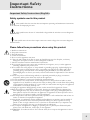
Safety symbols used in this product
This symbol alerts the user that there are important operating and maintenance instructions
in the literature accompanying this unit.
This symbol warns the user of uninsulated voltage within the unit that can cause dangerous
electric shocks.
This symbol warns the user that output connectors contain voltages that can cause dangerous
electrical shock.
Please follow these precautions when using this product:
1.
2.
3.
4.
5.
6.
Read these instructions.
Keep these instructions.
Heed all warnings.
Follow all instructions.
Do not use this apparatus near water.
Clean only with a damp cloth. Do not spray any liquid cleaner onto the faceplate, as this may
damage the front panel controls or cause a dangerous condition.
7. Install in accordance with the manufacturer's instructions.
8. Do not install near any heat sources such as radiators, heat registers, stoves, or other apparatus
(including amplifiers) that produce heat.
9. Do not defeat the safety purpose of the polarized or grounding-type plug. A polarized plug has
two blades with one wider than the other. A grounding-type plug has two blades and a third
grounding prong. The wide blade or the third prong are provided for your safety. When the
provided plug does not fit into your outlet, consult an electrician for replacement of the obsolete
outlet.
10. Protect the power cord from being walked on or pinched, particularly at plugs, convenience
receptacles, and the point where they exit from the apparatus.
11. Use only attachments or accessories specified by the manufacturer.
12. Use only with a cart, stand, bracket, or table designed for use with professional audio or music
equipment. In any installation, make sure that injury or damage will not result from cables pulling
on the apparatus and its mounting. If a cart is used, use caution when moving the cart/apparatus
combination to avoid injury from tip-over.
13. Unplug this apparatus during lightning storms or when unused for long periods of time.
14. Refer all servicing to qualified service personnel. Servicing is required when the apparatus has
been damaged in any way, such as when the power-supply cord or plug is damaged, liquid has
been spilled or objects have fallen into the apparatus, the apparatus has been exposed to rain or
moisture, does not operate normally, or has been dropped.
15. This unit produces heat when operated normally. Operate in a well-ventilated area with at least six
inches of clearance from peripheral equipment.
16. This product, in combination with an amplifier and headphones or speakers, may be capable of
producing sound levels that could cause permanent hearing loss. Do not operate for a long
period of time at a high volume level or at a level that is uncomfortable. If you experience any
hearing loss or ringing in the ears, you should consult an audiologist.
17. Do not expose the apparatus to dripping or splashing. Do not place objects filled with liquids
(flower vases, soft drink cans, coffee cups) on the apparatus.
18. WARNING: To reduce the risk of fire or electric shock, do not expose this apparatus to rain or
moisture.
9
Important Safety Instructions
Instructions de Sécurité Importantes (French)
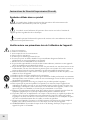
Symboles utilisés dans ce produit
Ce symbole alèrte l’utilisateur qu’il existe des instructions de fonctionnement et de
maintenance dans la documentation jointe avec ce produit.
Ce symbole avertit l’utilisateur de la présence d’une tension non isolée à l’intérieur de
l’appareil pouvant engendrer des chocs électriques.
Ce symbole prévient l'utilisateur de la présence de tensions sur les raccordements de sorties,
représentant un risque d'électrocution.
Veuillez suivre ces précautions lors de l’utilisation de l’appareil:
1.
2.
3.
4.
5.
6.
Lisez ces instructions.
Gardez ces instructions.
Tenez compte de tous les avertissements.
Suivez toutes les instructions.
N’utilisez pas cet allareil à proximité de l’eau.
Ne nettoyez qu’avec un chiffon humide. Il est potentiellement dangereux d'utiliser des
pulvérisateurs ou nettoyants liquides sur cet appareil.
7. Installez selon les recommandations du constructeur.
8. Ne pas installer à proximilé de sources de chaleur comme radiateurs, cuisinière ou autre appareils
(don’t les amplificateurs) produisant de la chaleur.
9. Ne pas enlever la prise de terre du cordon secteur. Une prise murale avec terre deux broches et une
troisièrme reliée à la terre. Cette dernière est présente pour votre sécurité. Si le cordon secteur ne
rentre pas dans la prise de courant, demandez à un électricien qualifié de remplacer la prise.
10. Evitez de marcher sur le cordon secteur ou de le pincer, en particulier au niveau de la prise, et aux
endroits où il sor de l’appareil.
11. N’utilisez que des accessoires spécifiés par le constructeur.
12. N’utilisez qu’avec un stand, ou table conçus pour l’utilisation d’audio professionnel ou instruments
de musique. Dans toute installation, veillez de ne rien endommager à cause de câbles qui tirent sur
des appareils et leur support.
13. Débranchez l’appareil lors d’un orage ou lorsqu’il n’est pas utilisé pendant longtemps.
14. Faites réparer par un personnel qualifié. Une réparation est nécessaire lorsque l’appareil a été
endommagé de quelque sorte que ce soit, par exemple losrque le cordon secteur ou la prise sont
endommagés, si du liquide a coulé ou des objets se sont introduits dans l’appareil, si celui-ci a été
exposé à la pluie ou à l’humidité, ne fonctionne pas normalement ou est tombé.
15. Puisque son fonctionement normale génère de la chaleur, placez cet appareil au moins 15cm. des
équipments péripheriques et assurez que l’emplacement permet la circulation de l’air.
16. Ce produit, utilisé avec un amplificateur et un casque ou des enceintes, est capable de produite des
niveaux sonores pouvant engendrer une perte permanente de l’ouïe. Ne l’utilisez pas pendant
longtemps à un niveau sonore élevé ou à un niveau non confortable. Si vous remarquez une perte
de l’ouïe ou un bourdonnement dans les oreilles, consultez un spécialiste.
17. N'exposez pas l'appareil à l'égoutture ou à l'éclaboussement. Ne placez pas les objets remplis de
liquides (vases à fleur, boîtes de boisson non alcoolique, tasses de café) sur l'appareil.
18. AVERTISSEMENT: Pour réduire le risque du feu ou de décharge électrique, n'exposez pas cet
appareil à la pluie ou à l'humidité.
10
Important Safety Instructions
Lesen Sie bitte die folgende Sicherheitshinweise (German)
Sicherheit Symbole verwendet in diesem Produkt
Dieses Symbol alarmiert den Benutzer, daß es wichtige Funktionieren und Wartung Anweisungen in
der Literatur gibt, die diese Maßeinheit begleitet.
Dieses Symbol warnt den Benutzer der nicht isolierten Spannung innerhalb der Maßeinheit, die
gefährliche elektrische Schläge verursachen kann.
Dieses Symbol warnt den Benutzer, dem Ausgabestecker Spannungen enthalten, die gefährlichen
elektrischen Schlag verursachen können.
Folgen Sie bitte diesen Vorkehrungen, wenn dieses Produkt verwendet
wird:
1.
2.
3.
4.
5.
6.
Lesen Sie die Hinweise.
Halten Sie sich an die Anleitung.
Beachten Sie alle Warnungen.
Beachten Sie alle Hinweise.
Bringen Sie das Gerät nie mit Wasser in Berührung.
Verwenden Sie zur Reinigung nur ein weiches Tuch. Verwenden Sie keine flüssigen Reinigungsmittel. Dies
kann gefährliche Folgen haben.
7. Halten Sie sich beim Aufbau des Gerätes an die Angaben des Herstellers.
8. Stellen Sie das Gerät nich in der Nähe von Heizkörpern, Heizungsklappen oder anderen Wärmequellen
(einschließlich Verstärkern) auf.
9. Verfehlen Sie nicht den Zweck des grounging Terminals auf dem Netzstecker. Dieses Terminal wird für
Ihre Sicherheit zur Verfügung gestellt.
10. Verlegen Sie das Netzkabel des Gerätes niemals so, daß man darüber stolpern kann oder daß es gequetscht
wird.
11. Benutzen Sie nur das vom Hersteller empfohlene Zubehör.
12. Verwenden Sie ausschließlich Wagen, Ständer, oder Tische, die speziell für professionelle Audio- und
Musikinstrumente geeignet sind. Achten Sie immer darauf, daß die jeweiligen Geräte sicher installiert sind,
um Schäden und Verletzungen zu vermeiden. Wenn Sie einen Rollwagen benutzen, achten Sie darauf, das
dieser nicht umkippt, um Verletzungen auszuschließen.
13. Ziehen Sie während eines Gewitters oder wenn Sie das Gerät über einen längeren Zeitraum nicht benutzen
den Netzstecher aus der Steckdose.
14. Die Wartung sollte nur durch qualifiziertes Fachpersonal erfolgen. Die Wartung wird notwendig, wenn das
Gerät beschädigt wurde oder aber das Stromkabel oder der Stecker, Gegenstände oder Flüssigkeit in das
Gerät gelangt sind, das Gerät dem Regen oder Feuchtigkeit ausgesetzt war und deshalb nicht mehr normal
arbeitet oder heruntergefallen ist.
15. Dieses Gerät produziert auch im normalen Betrieb Wärme. Achten Sie deshalb auf ausreichende Lüftung
mit mindestens 15 cm Abstand von anderen Geräten.
16. Dieses Produkt kann in Verbindung mit einem Verstärker und Kopfhörern oder Lautsprechern
Lautstärkepegel erzeugen, die anhaltende Gehörschäden verursachen. Betreiben Sie es nicht über längere
Zeit mit hoher Lautstärke oder einem Pegel, der Ihnen unangenehm is. Wenn Sie ein Nachlassen des
Gehörs oder ein Klingeln in den Ohren feststellen, sollten Sie einen Ohrenarzt aufsuchen.
17. Setzen Sie den Apparat nicht Bratenfett oder dem Spritzen aus. Plazieren Sie die Nachrichten, die mit
Flüssigkeiten (gefüllt werden Blumevases, Getränkdosen, Kaffeetassen) nicht auf den Apparat.
18. WARNING: um die Gefahr des Feuers oder des elektrischen Schlages zu verringern, setzen Sie diesen
Apparat nicht Regen oder Feuchtigkeit aus.
11
Important Safety Instructions
CE Declaration Of Conformity
See our website at:
http://www.alesis.com
FCC Compliance Statement
This device complies with Part 15 of the FCC rules. Operation is subject
to the following two conditions: (1) This device may not cause harmful
interference and (2) this device must accept any interference received,
including interference that may cause undesired operation.
NOTE: This equipment has been tested and found to comply with the
limits for a Class B digital device, pursuant to Part 15 of the FCC Rules.
These limits are designed to provide reasonable protection against
harmful interference in a residential installation. This equipment
generates, uses and can radiate radio frequency energy and, if not
installed and used in accordance with the instructions, may cause harmful
interference to radio communications. However, there is no guarantee
that interference will not occur in a particular installation. If this
equipment does cause harmful interference to radio or television
reception, which can be determined by turning the equipment off and
on, the user is encouraged to try to correct the interference by one or
more of the following measures:
-- Reorient or relocate the receiving antenna.
-- Increase the separation between the equipment and receiver.
-- Connect the equipment into an outlet on a circuit different from that
to which the receiver is connected.
-- Consult the dealer or an experienced radio/TV technician for help.
12
1 Connections
Connecting AC Power
Before making any power connections, make sure the Ion’s power switch
is turned off.
1. Plug the female end of the power cable into the Ion’s power socket.
2. Plug the male (plug) end into a properly grounded power outlet.
WARNING: Make sure the outlet is properly
grounded. Plugging the Ion into an
ungrounded outlet can be hazardous.
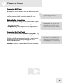
Making Audio Connections
There are a couple ways to hook up your Ion synthesizer’s audio outputs:
• Stereo. Connect two cables from the Ion’s left and right outputs to two
inputs of an amp or mixer.
• Headphones. Plug a set of headphones into the headphone jack on
the rear panel.
WARNING: When connecting audio cables
or turning power on and off, make sure that
the amplifiers in your system are turned off
or the volume controls are turned down. If
you don’t do this, you can create loud bursts
of sound that might damage your speakers.
Connecting the Foot Pedals
The Ion has two pedal jacks marked (sust pedal) and (exp pedal). Plug
a sustain pedal (not included) into the jack marked (sust pedal).
(sust pedal) is designed to work with any standard momentary
footswitch. It doesn’t matter whether the footswitch is normally open or
closed, as long as you plug it in before powering up your Ion; the
instrument will calibrate itself.
NOTE: If your sustain pedal response is
backward (i.e., notes sustain when your foot
is off the pedal), turn off your Ion and make
sure the footswitch plug is fully inserted into
the (sust pedal) jack. Then, turn the Ion back
on while keeping your foot off the footswitch.
(exp pedal) is designed to work with a Roland EV-5 pedal or equivalent.
13
1
Connections
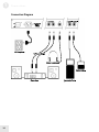
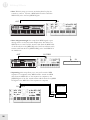
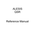
Connection Diagram
14
2 Overview
A Tour of the Front Panel
The display
The Liquid Crystal Display (LCD) is at the center of the Ion in more
ways than one. Depending on the button or knob you’ve activated, it may
show the program name, which Programs are used in a Setup, the values
of the parameters being edited, or even a graphic representation of a
waveform or an envelope.
There are four main screens that we’d like to describe in detail.
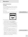
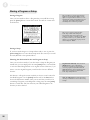
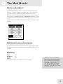
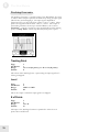
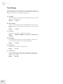
The Home page
This is the screen that shows you the most different kinds of information
all at once. If you’re not already there, press the [home] button and
you’ll see something like this:
Here’s what each area of the Home screen means:
• The darkened bar at the top of the screen shows you the name of
the section being displayed. In this case, it reads home.
• Immediately below that are the bank and program number.
• Roughly in the middle you see the program name of the active Part.
• The fourth line from the bottom shows the Setup number.
• Below that, the outlined rectangle shows the current Setup name.
• The “e box” icons to the right of the Program and Setup numbers
indicate that the Program and Setup have been edited, respectively.
• The filled rectangle on the second line from the bottom shows which
of the four Parts has been selected with the [panel active] buttons.
Note: the icon on the inside left of this box indicates that the current
Part has been muted.
• The “quarter note” icon, the “equal to” sign (=) and the numbers to
its right tell you what the tempo setting is for the Setup.
• The “G” to the right of the tempo value indicates the setting of the
Global mode parameter tempo source. If the “G” is there, that
means the tempo source parameter is set to global. This causes the
tempo to remain the same when you recall a new Setup or change
Programs. If the “G” is not there, the tempo source parameter is set
to program. In this case, the tempo value can change from one
Setup to the next, or when you call up another program in Part A.
• The “MIDI connector” icon and the number to its right indicate the
MIDI Channel of the currently selected Part.
A double-press of the [home] button also
shuts off all eight of the Ion’s voices and
sends an All Notes Off command over MIDI.
The Global mode parameter tempo source is
found on Global mode page 3, Soft button 2.
15
2
Overview
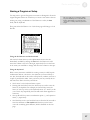
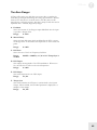
The Edit pages
Any time a knob is moved or a button is pressed, the Ion enters Edit
mode and displays a screen with parameters related to that knob or
button. The appearances of the pages can vary quite a bit, but there are
some things they have in common:
• There can be up to three parameters displayed on any page. If the
desired parameter does not have a front panel knob, select it using a
Soft button and turn the data knob to edit the value.
• Sometimes there are several pages of parameters related to a given
function. You will know this is the case by looking on the bottom
line of the page, as in the example below:
The numbers at the bottom of the page tell you how many pages there
are, and which page you are on. In the above example, there are five
pages available, and you are on page 1. When more than one page is
available, you can navigate to the additional pages using the [page X]
and [W page] buttons. Note that the arrow in the left corner is “grayed
out.” That means that there are no more pages available in that direction.
The Global pages
When the [global] button is pressed, the Ion will enter Global mode.
There are multiple Global pages, and each contains parameters related to
the way the Ion is configured. Select the desired parameter using a Soft
button and turn the data knob to edit the value. These settings do not
change from one Program or Setup to the next. For a complete
description of the Global mode parameters, see Chapter 3.
The Mod Matrix pages
When the [mod matrix] button is pressed, the Ion will enter Edit mode
for the active Program and display parameters related to the Mod Matrix.
This is also where the Tracking Generator is found. These are two of the
most powerful features of the Ion, allowing flexibility and control over
nearly every aspect of the sound. For a complete description of the Mod
Matrix and the Tracking Generator, see Chapter 6.
16
Remember: if there are two or more pages of
parameters related to a given function, use
the [page X] and [W page] buttons to
access the other pages.
Overview
2
LED functions
The Ion’s front panel has lots of LED lights. They serve many purposes:
•
•
•
Two LEDs serve as “speed” indicators: the rate LED and the
tempo LED. The rate LED may blink at a different speed
depending on which of three functions has been selected in the LFO
section: [lfo 1], [lfo 2], or [s&h].
The mod LEDs indicate that an edit has been made in the Mod
Matrix that affects one or more of the parameters in the section
where the mod LED is lit. If it isn’t obvious at first which parameter
is being “modded,” press the [mod matrix] button and look at the
lists of sources and destinations. For more information on the Mod
Matrix, see Chapter 6.
The loop LED is similar to the mod LEDs in that it indicates that
the loop parameter has been activated inside the selected envelope.
More information about looping the envelopes can be found on
pages 71-72.
Button functions
[edit] buttons – A green LED indicates that an [edit] button has been
pressed. This means that a particular set of parameters is being shown in
the display for inspection and editing.
Selection buttons – Some buttons allow you to select between different
sets of parameters that share a common knob or set of knobs. For
example, the [lfo 1], [lfo 2], and [s&h] buttons determine which of
those three functions will be controlled by the rate knob, and also call up
parameters from that function in the display. Similarly, the [pitch/mod],
[filter], and [amp] buttons determine which of those three envelopes
will be controlled by the five knobs in the env section.
Parameter buttons – Other buttons edit or toggle the parameter under
their control: for example, the [mono/poly] button or the [octave]
buttons in the osc section. Other examples include the [porta] button,
which enables portamento, and the [waveform select] buttons, which
determine the waveform utilized by each oscillator.
Special cases
[tap tempo] button – This button allows you to match the speed of the
arpeggiator, an LFO, or other effects to the tempo of a song simply by
tapping the button in time to the music! The LED under the button
flashes to give you an idea of what the tempo setting is currently.
NOTE: In order for an arpeggiator, LFO, or
effect to respond to the [tap tempo] button,
its sync parameter must be set to “tempo.”
[transpose] and [octave] buttons – These three buttons control the
global transposition and octave shift of the Ion’s keyboard. The settings
will affect all programs and setups, as well as the MIDI note output.
A double-press of the [transpose] button
resets the transposition amount to zero.
17
2
Overview
All Notes Off: the [home] button
In addition to taking you to the top level of a Program, the [home]
button serves a dual function: a quick double-press of this button will
shut off all eight of the Ion’s voices and send an All Notes Off
command over MIDI.
Knob functions
With the exception of the volume knob, all of the knobs on the Ion are
known as “360 pots,” as in “360 degrees of a circle.” This means they
don’t have a minimum or maximum physical position. When you grab
one, it will edit the value of the parameter it controls from there. This
prevents those annoying “jumps” between the value represented by the
position of the pot and the value stored in software for the parameter.
(Sometimes they can be very different.)
There are a few knobs that should be singled out for attention at this
point:
•
•
•
volume knob – This is the red knob just above the Pitch wheel. It
controls the level of the main and headphone outputs. Note that
this control has no effect on the aux outputs.
tempo knob – This is the knob in the upper left corner of the Ion. It
controls the speed of any number of functions, most notably the
arpeggiator.
data knob – This is the clear knob to the right of the display. Use it
for fine-tuning your edits, or to edit a parameter that has no frontpanel knob. It is also used for selecting Programs and Setups.
The functions of the rest of the knobs will be described in Chapter 5.
Performance controls
The Ion gives you a number of expressive controls at your fingertips, in
addition to all of the knobs and buttons:
•
•
•
•
Velocity – The Ion’s keyboard will respond to differences in how
hard you play the keys. You can tailor-make the keyboard’s response
to your playing style by selecting one of the nine keyboard curves
found on Global mode page 1, Soft button 2.
(p) or Pitch Bend wheel – This wheel is normally assigned to bend
the pitch of one or more oscillators, but it may be used as a source in
the modulation matrix to control nearly any parameter.
(m1) wheel – This wheel usually adds vibrato, but it also may be used
as a source in the modulation matrix to control nearly any parameter.
(m2) wheel – This wheel usually sweeps the filter, but it also may be
used as a source in the modulation matrix to control nearly any
parameter.
Even more control over the sound is available through the addition of an
optional expression pedal, such as the Roland EV-5. And don’t forget
that you can grab any knob and tweak it during performance!
18
Remember: In order for the S/H, an LFO, or
effect to respond to the tempo knob, its sync
parameter must be set to “tempo.”
3 Global Parameters
What does “Global” mean?
A Global parameter is one that affects the entire Ion at once: every
Program, every Setup, everything to do with MIDI or the arpeggiator,
etc. Since they are universal, Global parameters are not stored with
Programs or Setups.
A prime example of a Global setting is the LCD Contrast parameter on
Global mode page 1, Soft button 1. Whatever value you choose for this
parameter will affect the appearance of every single edit screen in the
Ion, and affect them all equally.
The Global parameters
To enter Global mode, press the [global] button.
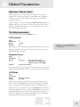
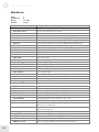
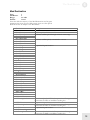
LCD Contrast
Page:
Soft Button:
Range:
Default:
1
1
1 to 180
100
Depending on your viewing angle or lighting conditions, you may want to
adjust this parameter. It controls the contrast between the text in the
LCD and the LCD’s backlight.
Remember: to reset any parameter to its
default value, perform a quick double-press
of its Soft button.
Keyboard Curve
Page:
Soft Button:
Range:
Default:
1
2
9 choices:
linear (low/med/high)
logarithmic (low/med/high)
exponential (low/med/high)
exponential medium
These settings allow you to configure the Ion to match your playing style.
Experiment with the different choices to see which curve suits you best.
LCD Mode
Page:
Soft Button:
Range:
Default:
1
3
edit only, lcd jump
lcd jump
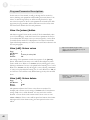
This parameter determines how the Ion will respond when you turn a
knob. A setting of edit only means the Ion will not update the display
when you turn a knob. You may prefer this when performing live, for
example, because you won’t have to press the [home] button in order to
know which program is active. A setting of lcd jump means the Ion will
respond immediately when you turn a knob and put that parameter’s
page on the display, with that parameter highlighted. You may find that
this setting works better for studio environments.
19
3
Global Parameters
Master Tune
Page:
Soft Button:
Range:
Default:
2
1
391.99 to 493.88 Hz
440.00 Hz
This parameter allows you to tune the Ion flat or sharp within a
significant range, to facilitate working with instruments that are not at
concert pitch.
Transpose
Page:
Soft Button:
Range:
Default:
2
2
-12 to +12 in chromatic steps
0
This parameter allows you to transpose the Ion’s keyboard up or down in
half-step increments over a total range of two octaves. There is an even
faster way to transpose the Ion: hold the [transpose] button and press a
key above or below the middle C on the keyboard, and the Ion will be
transposed by that amount. To transpose back to concert pitch, hold
[transpose] again and press the middle C. Another way to reset the
transposition amount to zero is to press the [transpose] button twice
quickly.
Octave
Page:
Soft Button:
Range:
Default:
2
3
-3 to +3
0
With this parameter you can transpose the Ion up or down in octave
increments over a range of 7 octaves, for a total range of 10 octaves
(including the range covered by the keyboard). This parameter also has a
pair of dedicated front panel buttons that will edit the value and take you
to this page.
MIDI Sync
Page:
Soft Button:
Range:
Default:
3
1
ext sync, gen midi clock, off
off
The Ion gives you the option to synchronize the arpeggiator, et al, to an
incoming MIDI clock. If a value of ext sync is selected, any function of
the Ion that has its sync parameter set to tempo will slave to the external
MIDI clock. If a value of gen midi clock or off is selected, the Ion will
ignore incoming MIDI clock messages. A setting of gen midi clock tells
the Ion to send out MIDI clock messages so external MIDI devices, such
as drum machines, can slave to the Ion’s arpeggiator.
20
A double-press of the [transpose] button
resets the transposition amount to zero.
NOTE: The settings of the Transpose and
Octave parameters will also change the
MIDI note output of the Ion by the same
amount.
Global Parameters
3
Tempo Source
Page:
Soft Button:
Range:
Default:
3
2
program, global
program
You may have noticed a reverse-colored “G” at the bottom of the Home
page. This icon appears when the tempo source parameter is set to
global. When it is, the tempo value will remain the same when you recall
a new Setup or change the program in Part A. When the tempo source
parameter is set to program, the “G” on the Home page goes away. In
this case, the tempo value can change from one Setup to the next, or
when you call up another program in Part A.
MIDI Bank Select
Page:
Soft Button:
Range:
Default:
3
3
cc 0, cc 32
cc 0
This parameter allows you to designate which MIDI controller number
the Ion will recognize and transmit as a Bank Select message.
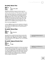
Mod Wheel 2 CC
Page:
Soft Button:
Range:
Default:
4
1
channel pressure, cc 2-4, 7-31, 64-95, 102-119
channel pressure
This parameter allows you to determine which MIDI controller or
controller number the Ion will transmit when you use (m2). It will also
consider incoming MIDI messages that match this setting to have been
generated by that wheel.
Exp Pedal CC
Page:
Soft Button:
Range:
Default:
NOTE: The exp pedal and (m2) are limited
to the use of certain MIDI controller (CC)
numbers. The CC numbers that are not
available are reserved for front panel knobs
and buttons. This allows your live edits to be
performed into a sequencer!
Remember: to reset a Global parameter to
its default value, perform a quick doublepress of its Soft button.
4
2
channel pressure, cc 2-4, 7, cc 7+vol, cc 8-31, 64-95,
102-119
cc 7+vol
This parameter allows you to determine which MIDI controller or
controller number the Ion will transmit when you use the expression
pedal. It will also consider incoming MIDI messages that match this
setting to have been generated by the pedal.
The default setting of cc 7+vol allows you to control the overall volume
of the Ion and send MIDI volume commands at the same time.
21
3
Global Parameters
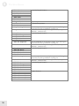
Exp Pedal Curve
Page:
Soft Button:
Range:
Default:
4
3
linear, exponential
linear
This parameter governs the response of the expression pedal. Try the
different options with your pedal to see which seems to work best.
Arp Send MIDI
Page:
Soft Button:
Range:
Default:
5
1
on, off
off
You have the choice to enable the arpeggiator to send the notes it
generates to an external device. A setting of on will allow your sequencer
to capture your performance exactly as it happened. It will also enable
the Ion to arpeggiate other synthesizers! If this parameter is set to off,
the arpeggiator will still control the Ion internally, but the Ion will only
send out the notes that you hold down.
Arp Retrigger
Page:
Soft Button:
Range:
Default:
5
2
key poly, key mono, mono
key poly
This parameter determines the way the arpeggiator will respond from
Part to Part within the Setup:
•
•
•
22
key poly – each Part’s arpeggiator functions independently. The
Part’s arpeggiator “clock” is reset when a note is played in that Part
and no other notes in the Part are being held down. This ensures
that the first note of an arpeggiation in a Part will sound immediately
when the key is hit.
key mono – there is effectively a single arpeggiator clock for all four
Parts. The clock is reset when a note is played and no other notes in
any Part are being held down. This ensures that the arpeggiators of
all four Parts will be synchronized.
mono – there is a single arpeggiator clock for all four Parts. This
clock is only reset when the “tap-tempo” button is pressed. This
allows the user to lock to an external beat using the “tap-tempo”
feature and have all arpeggiation thereafter synched to that beat.
Global Parameters
3
Analog Drift
Page:
Soft Button:
Range:
Default:
5
3
on, off
on
An analog synthesizer is a comparatively unstable device. Its components
tend to be imprecise, never producing a truly constant value. Synthesizer
enthusiasts call this tendency “drift,” and it is often cited as a major part
of the difference between the “warm” sound of analog synths and the
“cold” sound of digital synths.
The Ion can model the “drifting” behavior of analog synths as well. An
Analog Drift setting of on will cause the frequencies for each of the
oscillators and filters per voice to “drift” according to a special algorithm
we developed. To make the Ion sound even more realistic, they each drift
independently. Try it; it’s a subtle but very pleasing and effective feature.
Last Part Enable
Page:
Soft Button:
Range:
Default:
6
1
on, off
on
This parameter helps you configure how the Ion handles live edits of a
Setup. When set to on, it is not possible to disable the last active Part.
This helps you avoid accidentally turning off all of the Parts and getting
no sound. When set to off, any Part can be enabled or disabled from the
top panel, even if it is the only Part enabled. That way you can turn off
one Part before enabling another, as opposed to having to enable the
second Part before you can turn off the first Part.
P/M Wheel LEDs
Page:
Soft Button:
Range:
Default:
6
2
level track, always on
always on
The translucent (p) and (m) wheels have lights that illuminate them from
below. This parameter gives you the option of having those lights shine
at a static level (always on) or become brighter and darker as the wheels
are moved forward and backward (level track).
Pgm Write Protect
Page:
Soft Button:
Range:
Default:
6
3
on, off
on
When set to on, only the User Bank may be used to store Programs.
When set to off, Programs may be stored to any of the four Banks (Red,
Green, Blue or User). For more information, see the description of Store
mode on page 26.
Remember, Programs may be stored one at
a time, or an entire Bank may be moved
from one Bank to another or sent over MIDI.
This enables you to store your User bank in
a safer place, for example, while still having
it available on the keyboard when it’s time to
perform. The Program Write Protect Global
parameter makes this all possible.
23
3
Global Parameters
This page intentionally left blank.
24
4 Parts and Setups
What is a Setup?
A Setup is an arrangement of up to four Parts, which are Programs that
have been split or layered across the keyboard. The combined settings of
all four “zones” of the keyboard are what make up a Setup.
Programs vs. Parts
Parts reside at a slightly higher level of the Ion’s hierarchy than do
Programs. A Part consists of the Program plus settings for key range,
MIDI channel and controllers, panning, transposition, etc. You can select
a new Program within the Part without affecting these other settings.
Selecting Parts
To switch from one Part to another, use the four [panel active] buttons.
If you want to know which Programs are being used in a Setup, for
example, press the [home] button and then switch between the Parts
using these buttons. You don’t have to be at the Home page in order to
do this, though; you can switch between Parts no matter what page you
are editing. In addition to seeing the values of that page change as you
switch between the Parts, you will probably see the front panel LEDs
change to reflect their status in the different Programs.
A double-press of the [home] button also
shuts off all eight of the Ion’s voices and
sends an All Notes Off command over MIDI.
Selecting Programs
To select a new Program within the Part, use the [bank] and [select]
buttons, or simply press the [home] button and turn the data knob.
Note that calling up a new Program doesn’t change the split point, for
example, or the transposition amount.
How the Effects are Shared
Each of the four Parts in a Setup has its own Drive effect (compressor,
fuzz, etc.). However, they share a common stereo Effect (phaser, flanger,
vocoder, etc.). So even though the settings for both the Drive effect and
the stereo Effect are stored with each Program, it is the Program in Part
A that determines which stereo Effect the four Parts will share. This is
why you may hear the overall sound change more drastically when
changing the Program in Part A than you do when you change the
Program in one of the other Parts.
25
4
Parts and Setups
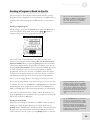
Storing a Program or Setup
Storing a Program
Once you have made an edit to a Program that you would like to keep,
press the [store] button to enter Store mode. You will see a screen that
looks like this:
The procedures for storing Programs and
Setups are nearly identical. Wherever they
differ we will point that out. However, as we
document the features and methods, the term
“Program” will stand for both Programs
and Setups unless otherwise specified.
There are two pages in Program Store
mode. Page 1 deals with storing the
Program internally; Page 2 deals with
storing it externally, or sending it over MIDI
in system exclusive (sys-ex) format. We will
address sys-ex functionality on pages 29-32
and in chapter 8 “MIDI.”
Storing a Setup
If you have made changes to a Setup and are ready to save it, press the
[store setup] button to enter Store Setup mode. The screen you see will
be nearly identical to that pictured above.
Choosing the destination for the new Program or Setup
Once you are in Store mode, if you don’t want to keep the Program you
started with, you can simply press the same [store] button a second time
to store the edited Program back to its original location. However, if you
want to save the original Program you will need to choose a different
location.
Soft button 1 calls up the screen in which you choose a new location for
the edited Program. Use the [select] buttons and/or the data knob to
choose the destination number. Once you are sure that you will not be
overwriting a Program you would prefer to keep, press the same [store]
button a second time. The Ion will store your edited Program to the
location you have selected.
26
Program Store mode only: You can use the
[bank] buttons to select a destination
location as well, but you will not be able to
store the program to any bank besides the
[user] bank unless you turn off the Program
Write Protect parameter in Global Edit
mode, Page 6, Soft button 3.
Note: The [select] buttons cannot be used for
choosing a destination location when storing
a Setup.
Parts and Setups
4
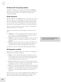
Naming a Program or Setup
You may want to give the Program a new name to distinguish it from the
original Program. There are several ways to create a new name or alter an
existing one, using a combination of Soft buttons 1 and 2, the data
knob, and the keyboard.
The exact same process is used for naming
Programs and Setups. As we document the
features and methods, we will use the term
“Program” to stand for both Programs and
Setups.
First, press either Soft button 2 or 3. The Store page will change to look
like this:
Using the Soft buttons and the data knob
The vertical column shows you the alphanumeric choices that are
immediately available by turning the data knob. Soft buttons 2 and 3
move this column to the left or the right, respectively. Choose the letter
in the name you would like to change and move the column to that spot.
Using the keyboard
With so many characters available for creating a name, it could be quite
cumbersome without a shortcut to the characters you’re most likely to
use. The Ion keyboard can be used to call up letters, numbers, and even a
couple of punctuation marks. Once you know your way around, this is a
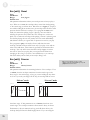
real time-saver. Here’s how they are laid out:
• The lowest C on the keyboard enters a space.
• Starting with the D above that, the white keys are used to enter the
letters of the alphabet. For example, the lowest D key enters the
letter “A.” The top A key on the keyboard enters “Z.” And if you hit
one of these keys repeatedly, the letter will switch from uppercase to
lowercase.
• The top B and C keys enter an exclamation point ( ! ) and a question
mark ( ? ) respectively.
• The black keys in the second and third octaves from the left are used to
enter the numbers 0-9. Be careful! The black keys in the lowest
octave do something quite different, which is detailed on the next
page.
27
4
Parts and Setups
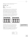
Inserting and deleting characters using the keyboard
The two lowest black keys perform a special function.
• The Db key will insert a space, taking all letters to the right of and
including the vertical column and pushing them to the right. Once a
letter exceeds the right-most side, it is erased.
• The Eb key will delete a space, taking all letters to the right of and
including the vertical column and pulling them to the left. Once a
letter enters the vertical column, it is erased.
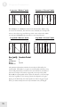
The complete cast of characters
The following chart includes all of the characters that are available when
creating a name.
Character chart
A
!
|
a
28
B
?
~
b
C
.
^
c
D
,
:
d
E
+
;
e
F
&
f
G
=
0
g
H
@
1
h
I
$
2
i
J
#
3
j
K
%
4
k
L
“
5
l
M
`
6
m
N
'
7
n
O
\
8
o
P
/
9
p
Q
(
R
)
S
<
T
>
U
{
V
}
W X
[
]
Y
_
Z
*
q
r
s
t
u
v
w
y
z
x
Parts and Setups
4
Sending a Program or Bank via Sys-Ex
The second page of Store mode contains features related to storing a
Program or bank of Programs on an external device via MIDI, such as a
computer with a librarian program, a MIDI data filer, or even another
Ion.
The processes for transmitting Programs
and Setups over MIDI are slightly different.
We will cover the process for Programs in
this section. The process for transmitting
Setups is documented on page 31.
Sending a single Program
The first thing to do is press the [store] button above the data knob, if
you’re not already in Store mode. Next, use the [page X] button to
navigate to page 2. You’ll see a page that looks like this:
The “from” location over Soft button 1 should be the same as the
number of the Program you were editing. The “to” location must be
selected carefully. When you press the [store] button the second time,
a little marker is placed in the Program data that tells the Ion to put the
Program in the “to” location when it is sent back via MIDI. This is fine
if you’re expecting it, but if you aren’t it can be difficult to find the
Program that was sent over. You may not remember what the original
location of the Program was when you sent it out. There’s a solution to
this dilemma, but we’ll write about that in the section called “Special
Cases” on the next page. We have other things we need to cover first.
Be sure the Program number in the “from” category is the one you want
to send out. If it isn’t, use the data knob or [select] buttons to select the
proper Program. Then use Soft button 2 to select the “destination” to
which your MIDI device will send the Program when it is retransmitted.
Once you have selected the source (“from”) and the destination (“to”),
press the [store] button a second time. The sys-ex data for that Program
will be sent out the Ion’s MIDI jack.
Sending an entire Bank
The process for sending an entire Bank over MIDI is much the same as
sending out a single Program. From page 2 of Store mode, use the
[select] buttons or data knob to change the “from” value until it reaches
Program 127 in the current Bank. Then turn the data knob one more
value clockwise to the “all” option. Use the [bank] buttons to select the
Programs and Banks may be moved from
one Bank to another when sent over MIDI.
In order for a User Program or Bank to be
received by the Blue bank, for example, the
“from” and “to” Bank locations must be set
properly. Then when the Program or Bank is
sent back to the Ion, the Global “Program
Write Protect” parameter must be set to
“off.”
Tip: use the [bank] buttons as a shortcut to
get from a low Program number to a high
one, whatever mode you’re in. For example,
if you have User Program 0 selected on the
Home page and you want to reach User
Program 127 quickly, turn the data knob one
click counter-clockwise, which will take you
to Blue Program 127. Then press the [user]
bank button and you’re there!
29
4
Parts and Setups
bank you wish to transmit (“from”) and the bank you wish it to come
back as (“to”). Press [store] a second time and the Bank will be sent out
the Ion’s MIDI jack.
Special cases
Store Program mode
There are a few options between the “User:all” and the “Red:000”
choices of the “Send Program to MIDI” page that should be pointed
out. They are called edit:a, edit:b, edit:c, and edit:d. These stand for
the four Program edit buffers in the current Setup.
Of course, these are useful as a “from” location, but they are even more
useful as a “to” location. Herein lies the solution to the problem of
knowing where a Program will arrive when it is sent back to the Ion via
MIDI, and wondering if it will accidentally overwrite something you
wanted to keep. The solution: always select one of the edit buffers as
the “to” location. When the Program comes back, you won’t have to go
fishing for it in the middle of a Bank of 127 Programs; it’ll be in one of
four non-destructive locations. If you want to narrow it down even
further, always select the same edit buffer, be it edit:a or edit:d, as the
destination. If you’re consistent with this, you’ll save yourself a lot of
headaches later on.
Store Setup Mode
The “Send Setup to MIDI” page, discussed immediately below, has an
extra option called “edit” that is equivalent to the edit:a-d options on the
“Send Program to MIDI” page. If you want to keep your options open
when transmitting a single Setup to MIDI, select the “edit” option as the
“to” location. That way it will always be returned to the Setup edit buffer,
where you can place it in a location known at that time to be available.
30
Parts and Setups
4
Sending One Setup or All Setups via Sys-Ex
The second page of Store mode contains features related to storing one
Setup or all 32 Setups on an external device via MIDI, such as a
computer with a librarian program, a MIDI data filer, or even another
Ion.
Be sure to read the previous section,
“Special Cases,” for an explanation of the
“edit” option found on the “Send Setup to
MIDI” page.
Sending a single Setup
The first thing to do is press the [store setup] button to the right of the
[part enable] buttons, if you’re not already in Store Setup mode. Next,
use the [page X] button to navigate to page 2. You’ll see a page that
looks like this:
The “from” location over Soft button 1 should be the same as the
number of the Setup you were editing. The “to” location must be
selected carefully. When you press the [store setup] button the second
time, a little marker is placed in the Setup data that tells the Ion to put
the Setup in the “to” location when it is sent back via MIDI. This is
fine if you’re expecting it, but if you aren’t it can be difficult to find the
Setup that was sent over. You may not remember what the original
location of the Setup was when you sent it out. There’s a solution to this
dilemma, and that information is covered in the section called “Special
Cases” on the previous page.
Be sure the Setup number in the “from” category is the one you want to
send out. If it isn’t, use the data knob to select the proper Setup. Then
use Soft button 2 to select the “destination” to which your MIDI device
will send the Setup when it is retransmitted.
Once you have selected the source (“from”) and the destination (“to”),
press the [store setup] button a second time. The sys-ex data for that
Setup will be sent out the Ion’s MIDI jack.
Sending all Setups
The process for sending all of the Setups over MIDI is much the same as
sending out a single Setup. From page 2 of Store mode, use the data
knob to change the “from” value until it reaches Setup 31. Then turn the
data knob one more value clockwise to the “all” option. Press [store] a
second time and the Bank will be sent out the Ion’s MIDI jack.
31
4
Parts and Setups
Sending All Programs and Setups via Sys-Ex
There is a method for backing up all 512 Programs, all 32 Setups, and
your Global settings at one time. You can access this option from either
Store Program mode or Store Setup mode. In either case, it is on page 2,
Soft button 3. To initiate the bulk dump, navigate to this screen and press
the same [store] button a second time. All data will be sent out the Ion’s
MIDI jack.
Storing and Recalling Setups
There are 32 Setup locations available in the Ion, all of which may be
overwritten with your own Setups. The procedure for storing a Setup is
essentially identical to that for storing a Program. For information on this
process, see the section “Storing a Program or Setup” on page 26.
Recalling a Setup
When the Ion is first turned on, it will automatically recall the last Setup
you were on when you turned the unit off. If you want to call up a
different Setup, press the [recall setup] button. You will see a screen
that looks like this:
As you can see from the illustration above, the Recall Setup screen shows
you all four Parts within the current Setup and the names and locations
of the Programs they use. The boxes on the left indicate whether or not
each of the four Parts is active in the current Setup. If a box is checked,
its Part is active.
Use the data knob to recall one of the 32 Setups. As soon as you turn
the knob, the new Setup will become the current Setup. As evidence of
the change, you will see the [part enable] buttons turn on or off
depending on whether the Parts they represent are active in the current
Setup.
32
Caution! As soon as you turn the data knob
you will lose the current Setup. Be sure you
have saved any edits you would like to keep
before selecting a new Setup.
Parts and Setups
4
Compare Mode
When you select a new Program or recall a Setup, it is placed in a
temporary workspace known as an “edit buffer.” There is an edit buffer
for each Program within the current Setup and for the Setup itself. This
allows you to edit the Program or Setup without affecting the original
stored version of the item. If at any time you want to compare the edits
you have made to the original Program or Setup, press the [compare]
button.
When you press the [compare] button its LED will light, and all four
Programs and the Setup will switch to their original stored versions. To
return to the edited versions, press the [compare] button again. Its LED
will turn off and your edits will be restored.
While in Compare mode, you will be unable
to make any edits to the Programs or the
Setup (except to enable or disable the Parts).
If an edit is attempted, the [compare] LED
will flash to remind you that you are in
Compare mode.
Part Parameter Descriptions
In this section of the manual we will go through the Part parameters one
at a time, defining each parameter and describing how each affects the
Setup. The parameters are listed by the Edit Part page name, the page
number, and the Soft button used to access them. Also listed is the
default value for each parameter.
Program Bank
Page:
Soft Button:
Range:
Default:
1
1
red, green, blue, user
user
This parameter simply shows you the status of the [bank] buttons to the
right of the data knob. You could just look, of course, but the existence
of this parameter drives home the point that a given Program is actually a
component of a Part, which in turn is part of a Setup. This parameter
ensures that the next time you recall the Setup, the proper Program from
the proper Bank will be recalled into this Part as well.
Program
Page:
Soft Button:
Range:
Default:
1
2
000-127
000
As with the Program Bank parameter, the Program parameter ensures
that the next time you recall the Setup, the Program number will be
remembered and recalled into this Part. Remember that the Program is
actually a component of a Part, which in turn is part of a Setup.
This page also shows you six Programs at a time, which is handy when
you’re searching for a particular Program.
33
4
Parts and Setups
MIDI Channel
Page:
1
Soft Button:
3
Range:
1-16
Default:
1
This parameter defines the MIDI Channel for the selected Part. This is
the channel on which all data for this Part will be transmitted and
received.
MIDI/Local
Page:
Soft Button:
Range:
Default:
2
1
midi only, local only, midi+local
midi+local
This parameter determines the keyboard and MIDI transmit and receive
status for the selected Part:
•
•
•
midi only – equivalent to “local off.” The selected Part’s Program
will not be heard when the keys are played. However, the Ion will
send and receive MIDI data to and from an external device.
local only – the selected Part’s Program may be played from the
keyboard, but the Ion will not transmit or respond to external MIDI
data.
midi+local – the selected Part’s Program may be played from the
keyboard, and the Ion will transmit MIDI data to an external device
for this Part.
Low Key
Page:
Soft Button:
Range:
Default:
2
2
0-127
0
To limit the number of keys the selected Part occupies, use this
parameter and the next one, High Key. You may use the data knob to set
or adjust the lower limit of the Part’s range, but a faster way is to hold
Soft button 2 and press the desired key. The Low Key value will update
to reflect the MIDI number of the key you pressed.
High Key
Page:
Soft Button:
Range:
Default:
2
3
0-127
127
To limit the number of keys the selected Part occupies, use this
parameter and the previous one, Low Key. You may use the data knob to
set or adjust the upper limit of the Part’s range, but a faster way is to
hold Soft button 3 and press the desired key. The High Key value will
update to reflect the MIDI number of the key you pressed.
34
NOTE: in all three cases, the selected Part
will still respond to incoming MIDI data.
Remember: to reset a parameter to its
default value, perform a quick double-press
of its Soft button.
Tip: If the Low Key is set higher than the
High Key, the Ion will create a “hole” in the
middle of the Part where no voices will play.
Parts and Setups
4
Out Level
Page:
Soft Button:
Range:
Default:
3
1
0-100%
100%
The Out Level parameter sets the level of the Part within the Setup. It is
distinct from the Program Output Level parameter controlled by the
knob on the right side. This parameter allows you a further level of mix
control so you can balance the levels of the Parts without editing the
level stored with the Program. Remember, it’s possible that Program
might be used in another Setup, so it’s better to make this adjustment
inside the Part.
Out Balance
Page:
Soft Button:
Range:
Default:
3
2
center, 1-100% main, 1-100% aux
center
The Out Balance parameter determines whether the selected Part will be
sent to the main output, the aux output, or a definable mix of both.
This gives you the capability of isolating a Part in one set of stereo
outputs, or even sending each Part in the Setup to a separate, mono
output (when used in conjunction with the Pan parameter described on
the next page).
EFX Level
Page:
Soft Button:
Range:
Default:
3
3
0-100%
100%
The EFX Level parameter sets the Effects level of the Part within the
Setup. This is not to be confused with the Program Effects Level
parameter controlled by the knob on the right side. Remember, the
Program in Part A selects the shared Effect for all four Parts. You may
want to adjust the amount of Parts B through D being sent to that
Effect; that is what this parameter allows you to do.
The EFX Level parameter serves as a Send
Level control to the shared Effect. It does not
override the level of the Drive effect, as each
Program retains its own Drive effect in a
Setup. You can edit this level using the Drive
knob. Once you have the Drive effect level
set the way you like it, be sure to store the
Program so your changes are remembered!
Otherwise these settings will be lost when
you recall a new Setup.
Pan
Page:
Soft Button:
Range:
Default:
4
1
center, 1-100% L, 1-100% R
center
The Pan parameter determines the position of the selected Part in the
stereo field. When used in conjunction with the Out Balance parameter
described on the previous page, it is possible to send each Part in the
Setup to a separate, mono output.
35
4
Parts and Setups
Sust Pedal Enable
Page:
Soft Button:
Range:
Default:
4
2
on, off
on
When this parameter is set to on, the currently selected Part will respond
to the sust pedal and will send and receive sustain pedal commands via
MIDI. When set to off, the selected Part will neither send nor respond to
sustain pedal commands.
Exp Pedal Enable
Page:
Soft Button:
Range:
Default:
4
3
on, off
on
When this parameter is set to on, the currently selected Part will respond
to the exp pedal and will send and receive exp pedal controller messages
via MIDI. When set to off, the selected Part will neither send nor
respond to exp pedal messages.
Pitch Wheel Enable
Page:
Soft Button:
Range:
Default:
5
1
on, off
on
When this parameter is set to on, the currently selected Part will respond
to the (p) wheel and will send and receive pitch bend messages via
MIDI. When set to off, the selected Part will neither send nor respond to
pitch bend messages.
Mod 1 Wheel Enable
Page:
Soft Button:
Range:
Default:
5
2
on, off
on
When this parameter is set to on, the currently selected Part will respond
to the (m1) wheel and will send and receive controller 1 messages via
MIDI. When set to off, the selected Part will neither send nor respond to
controller 1 messages.
36
The MIDI continuous controller numbers for
(m2) and the exp pedal are selected in the
Global parameter section. To select a
different value, go to Global Edit page 4,
Soft buttons 1 and 2, respectively.
Parts and Setups
4
Mod 2 Wheel Enable
Page:
Soft Button:
Range:
Default:
5
3
on, off
on
The MIDI continuous controller numbers for
(m2) and the exp pedal are selected in the
Global parameter section. To select a
different value, go to Global Edit page 4,
Soft buttons 1 and 2, respectively.
When this parameter is set to on, the currently selected Part will respond
to the (m2) wheel and will send and receive its assigned controller
number information via MIDI. When set to off, the selected Part will
neither send nor respond to MIDI messages at its assigned controller
number.
Transpose
Page:
Soft Button:
Range:
Default:
6
1
-12 to +12 in chromatic steps
0
This parameter allows you to transpose the selected Part up or down in
half-step increments over a total range of two octaves, independently of
the other Parts. In this way you can transpose one Part chromatically
without affecting the other Parts in the Setup.
NOTE: The settings of the Part Transpose
and Part Octave parameters will not change
the MIDI note output of the selected Part.
Octave
Page:
Soft Button:
Range:
Default:
6
2
Range:
0
-3 to +3
With this parameter you can transpose the selected Part up or down in
octave increments over a range of 7 octaves, for a total range of 10
octaves (including the range covered by the keyboard). This allows you,
for example, to drop a bass by a couple of octaves and raise a brass
sound by an octave without affecting the other Parts in the Setup.
37
4
Parts and Setups
This page intentionally left blank.
38
5 Program Parameters
How the Ion Makes Sound
The Ion generates sound by emulating, or “modeling,” the behavior of
an analog synthesizer. Generally, it is helpful to think in terms of the
signal moving from the left side of the top panel to the right side. The
oscillators are fed into the filters, which in turn are fed into the
amplifiers.
As the signal moves through that basic path, you are able to adjust the
mix of the signal at several points, apply various modulations and
envelopes, and add effects. In this way, the Ion can generate a virtually
limitless variety of sounds.
Let’s take a quick look at the Ion’s signal path, from start to finish.
The Oscillators
The oscillators are where sound is born. You may have heard that what
you perceive as “sound” is simply vibrating air molecules hitting your
eardrums. That vibration has to start somewhere, and in the Ion, it
comes from the oscillators. By varying the frequency of the vibration, the
oscillators can produce different pitches, which are heard as musical
notes. By adjusting the waveform type and shape, the oscillators can produce
various harmonics, which are heard as different timbres. Each of the
Ion’s voices contains three oscillators.
The Pre Filter Mix
The outputs of the oscillators, as well as a few other signal sources, are
fed into a virtual mixing board called the Pre Filter Mix. The job of this
mixer is to funnel all of these sources into the inputs of the next sound
processing stage—the filters. For each source, you can specify its level,
which is how loud it should be, and its balance, which determines how
much of it goes to Filter 1 and how much to Filter 2.
The Filters
The sound produced by the oscillators is very raw, and usually not
suitable to be used directly in an instrument. In order to bring out the
sonic textures you have in mind, you will typically want to dampen
certain harmonics and boost others. This is where the filters come in.
Filters alter the frequency content of the signal, and can have a drastic
effect on the sound. A filter typically allows you to adjust its cutoff
frequency, which represents the range of harmonics that the filter operates
on, as well as its resonance, which determines how much boost is given to
harmonics around the cutoff frequency. Each of the Ion’s voices
contains two filters, and each filter can be one of eighteen different types,
each with its own character and sonic flavor.
39
5
Program Parameters
The Post Filter Mix
The outputs of the filters need their own virtual mixing board as well,
and that’s what the Post Filter Mix is for. For each filter output, as well
as a pre filter signal of your choice, you can specify a level, which is how
loud it should be, and a pan, which determines how much goes to your
left speaker and how much to the right.
Output
The sound is getting near the end of its journey, but still has one more
processing stage to go through. In the output stage, the Ion allows you
to apply a drive effect, to give the sound a final push and add some
compression, distortion, or other amplification effect. You also get to
choose the overall level for the sound, as well as how much of it gets sent
to the Ion’s dedicated effects processor.
Signal Flow Diagram
osc 3
filter 2
osc 1
ring mod
noise
filter 1
pre filter signal
Post Filter Mix
Pre Filter Mix
osc 2
L
R
external
inputs
L
R
amp
envelope
drive
aux output
output level
pan
main/aux balance
wet/dry
mix
effects
40
main output
Program Parameters
5
Modulation
At this point, you may think that producing a sound with the Ion is
simply a matter of configuring the parameters for the oscillators, filters,
and mixers, and then hitting a key. And although it’s true that you can
design some nice instruments this way, generating the really awesome
sounds invariably involves tweaking some of those parameters while a
note is playing. The problem with that, if you’re anything like us, is that
you only have two hands, and you are probably using at least one of
them to hit the notes in the first place. Fortunately, the Ion is willing to
lend you a helping hand—twelve of them, in fact.
The Ion allows you to set up twelve modulation routes. Each of these is a
virtual connection between some physical or internally-generated source
and some program parameter. Basically, a mod route tells the synth to
automatically grab a knob and tweak it while a note is playing. Although
there are quite a few sources that you can use for your mods, the most
common ones involve the LFOs and the envelopes.
The LFOs
LFO stands for “low frequency oscillator”. Unlike the normal oscillators,
however, the LFOs are not designed for producing sound. Instead, their
purpose is to tweak a program parameter according to a looping pattern.
For example, if you are looking to add some vibrato to your instrument,
you’ll need the pitch to continuously waver up and down. An LFO is
perfect for this application. Simply hooking up an LFO to the oscillator
pitch parameter will get you the effect you need. Each of the Ion’s
voices contains two LFOs.
The Envelopes
If you hit a note on a piano, you’ll hear a burst of sound energy as the
hammer strikes the string, followed by lower level of loudness as you
hold down the note and let the string ring out, which fades quickly as
soon as you release the note and the damper is applied. Synthesizer
designers model this behavior using ADSR envelopes. ADSR stands for
“attack, decay, sustain, release”, and represents the different stages that
the sound goes through over the life of the note. Since the most
important application of the envelope is to control the loudness of the
sound, the Ion provides one envelope that is specifically designed for this
purpose. This is the amp envelope. However, envelopes are useful in all
sorts of mod routes, which is why you can hook up any of the Ion’s
envelopes to any modulatable program parameter. Each of the Ion’s
voices contains three envelopes.
41
5
Program Parameters
Program Parameter Descriptions
In this section of the manual, we will go through the Ion section by
section, defining each parameter and describing how each relates to the
others. As with the signal flow, we will be moving from left to right
across the front panel of the Ion. The parameters are listed by the Edit
page name, the page number, and the Soft button used to access them.
Also listed is the default value for each parameter.
Voice: the [unison] button
This button toggles Unison mode on and off. It also immediately takes
you to Voice Edit page 1 with the Unison Voices parameter selected, so
you can determine how many voices you want assigned to one key when
you enable Unison mode. For a description of the three Unison mode
types and related parameters, see Unison voices and Unison detune in the
next two paragraphs.
Voice [edit]: Unison voices
Page:
Soft Button:
Range:
Default:
1
1
2 voices, 4 voices, full
full
The setting of this parameter controls the response of the [unison]
button. It determines how many voices will be allocated per key when
Unison mode is on. When set to 2 voices each key will trigger 2 voices,
allowing a maximum of 4 keys to be played before running out of voices.
When set to 4 voices each key will trigger 4 voices, allowing a maximum
of 2 keys to be played before running out of voices. When set to full, all
8 of the Ion’s voices will be evenly divided among the keys that are held
down.
Voice [edit]: Unison detune
Page:
Soft Button:
Range:
Default:
1
2
0-100
0
This parameter detunes the Unison voices from one another. For
example, with a Unison voices setting of 2 voices and a Unison detune
setting of 15, voice 1 will be detuned +15 cents and voice 2 will be
detuned –15 cents. In the same scenario with Unison voices set to 4
voices or full, the Unison voices will be spread out between those limits.
The higher the Unison detune setting, the more spread out the voices
will be.
42
Tip: to return quickly to page 1 while
editing, perform a quick double-press of the
[edit] button in that section.
Remember: to reset a parameter to its
default value, perform a quick double-press
of its Soft button.
Program
m Parameters
5
Voice [edit]: P Wheel mode
Page:
Soft Button:
Range:
Default:
1
3
held, all
all
The setting of this parameter dictates the response of the (p) wheel,
which is normally assigned to pitch bend. When set to all, moving this
wheel will bend the pitch of all voices that are sounding, even if they are
being sustained by the (sust pedal) or are in their release stage.
When this parameter is set to held, only voices for which the keys are
still depressed will allow their pitch to be bent by the (p) wheel. This is a
great feature that can allow a keyboard player to bend notes in a chord
independently, like a guitar player can. For example, if you play a threenote chord, step on the (sust pedal), and release the top and bottom
keys, you can bend the pitch of the note in the middle while the two
released notes are being sustained at their original pitches.
Voice: the [porta] button
This button toggles Portamento mode on and off. It also immediately
takes you to Voice Edit page 2 with the Portamento Rate parameter
selected. The four Portamento types and related parameters are described
in the next paragraph and on the next page.
Voice [edit]: Portamento type
Page:
Soft Button:
Range:
Default:
2
1
fixed, scaled, gliss fixed, gliss scaled
fixed
Tip: to return quickly to page 1 while
editing, perform a quick double-press of the
[edit] button in that section.
Pressing the [porta] button turns on the Portamento feature, which is
also sometimes called “glide.” This adds a very distinctive character to a
sound, causing played notes to slide from one pitch to the next instead
of changing only in “hard” intervals.
You have a choice of four different Portamento types:
fixed
scaled
gliss fixed
gliss scaled
No matter how far apart the two keys are, it takes the
same amount of time to travel between them. The
Portamento time parameter determines this amount
of time.
Determines the amount of time it takes to glide a
distance of one octave.
The response between two keys is the same as for fixed,
but the pitch travels in chromatic increments between
the notes (C, C#, D, etc.).
The response between two keys is the same as for
scaled, but the pitch travels in chromatic increments
between the notes (C, C#, D, etc.).
43
5
Program Parameters
Voice [edit]: Portamento time
Page:
Soft Button:
Range:
Default:
2
2
10 msec to 10 seconds
160.22 msec
Remember: to reset a parameter to its
default value, perform a quick double-press
of its Soft button.
This parameter determines the length of time it takes for the Portamento
feature to slide from note to note. The exact response is determined by
the Portamento type parameter. See the previous parameter description
for more information.
Voice [edit]: Portamento trigger
Page:
Soft Button:
Range:
Default:
2
3
normal, legato
normal
Portamento can be configured to respond in one of two ways to the way
you play:
legato
normal
The effect of the Portamento trigger
parameter may be easier to see when a
Program is in Mono mode.
Portamento will occur only if you play a second key
before lifting up the first key.
Portamento will occur even if there is no overlap
between the lifting of one key and the playing of
another.
Voice: the [mono/poly] button
This button toggles between the mono and poly voice modes. Mono
mode allows only one voice to be played. Poly mode allows polyphonic
operation. Since it’s a dedicated button with only two potential values, it
doesn’t call up a parameter in the display.
LFO [edit]: Rate
Page:
Soft Button:
Range:
Default:
1
1
0.010 – 1000 hz or x 16 – x 1/16
0.100 hz
This is where the initial rate for the selected LFO is set. Of course, the
easiest way to edit this particular parameter is to grab the rate knob and
turn it. That will take you immediately to this page.
Note that there are two possible sets of values listed for this parameter’s
range. The set of values you will have available is determined by the sync
parameter on LFO edit page 1, Soft button 2.
The first Range (0.010 – 1000 Hz) is available if the Sync parameter is set
to off. This means the LFO is not synchronized to the setting of the
tempo parameter. As a result, the LFO may be set to any rate within the
first range of values.
44
Note: Although each LFO is entirely
independent, their parameters are identical.
Therefore, in discussing each parameter we
will make no distinction between LFO 1 and
LFO 2. Everything said about the
parameters for either LFO applies equally to
the other.
When LFO sync is set to off, LFO rate
values are measured in Hz, or Hertz. This is
a term meaning “cycles per second,” and it
is often referred to as the frequency of the
LFO. A setting of 1000 Hz is well within the
range of human hearing, so that rather than
simply hearing the effect the LFO has on the
pitch of an oscillator, the LFO itself can be
heard as well.
Program
m Parameters
The second Range (x 1/16 – x 16) is provided if the Sync parameter is
set to on. This means the LFO is synchronized to the setting of the
tempo parameter. As the tempo changes, so will the rate of the LFO. But
the difference here is that there is a rhythmic relationship between the
tempo and the rate of the LFO. When the value is set to x 1 (“times
one”), the LFO will complete its cycle once per quarter note, relative to
the tempo setting. When the value is set to x 2, the LFO will cycle once
per eighth note. A value of x 16 results in an LFO cycle of 1/64th note,
and a value of x 1/ 16 results in an LFO cycle equivalent to sixteen
quarter notes, which are represented by four whole notes in the LCD
graphics.
5
Remember that if you want to edit the rate
for one of the LFOs using the rate knob, you
must first be sure the appropriate button has
been pressed in the LFO section. The same
is true for any LFO parameter you wish to
edit.
LFO [edit]: Sync
Page:
Soft Button:
Range:
Default:
1
2
tempo, off
off
As described in the section on LFO rate, this parameter determines
whether the LFO is synchronized, or “slaved,” to the master tempo
setting. For a complete description of how that affects the function of
the LFO, refer to the previous parameter description.
Note: It is possible to set the LFO sync
values independently per LFO, so that one
LFO is slaved to the tempo setting and the
other LFO is “free running.”
LFO [edit]: Reset
Page:
Soft Button:
Range:
Default:
1
3
mono, poly, key-mono, key-poly
mono
The LFO Reset parameter dictates how the LFO will respond when the
first key is pressed, and then determines how it will react to overlapping
keypresses. There are four types of possible responses:
mono
The LFO is shared between the voices of a Part. It may
be at any point in its cycle when the first key is pressed.
New voices will “ride” that LFO, joining other voices at
the exact same point in the LFO’s cycle. The LFOs in
each Part are independent of each other, so they can be
running at different speeds.
poly
Each voice’s LFO is completely independent of the
others. When a key is pressed, that voice’s LFO may be
at the top of its cycle, at the bottom, or anywhere else
in the cycle when it begins to affect the voice. Some
LFOs may be going in one direction (rising) while
others are going in the opposite direction (falling).
key-mono
The LFO is shared between the voices of a Part. When
the first key is pressed, the LFO’s cycle resets to the
beginning. When a second key is pressed, the LFO will
reset its cycle to the beginning and start over.
key-poly
Each voice has its own LFO that resets when the voice
is triggered.
Remember that it is possible to have the
LFOs set independently, so that one LFO’s
Reset parameter may be set to poly, for
example, while the other’s is set to keymono.
45
5
Program Parameters
LFO [edit]: M1 to LFOx
Page:
Soft Button:
Range:
Default:
2
1
0-100%
0%
There are several ways to use an LFO, but the two main ways are as an
expressive modulation source tied to one of the wheels, or as a constant
modulation source for some aspect of the sound. This parameter
determines whether the LFO will be used as one or the other, or as a
blend of both.
If you want the LFO only available from (m1), set this parameter to
100%. If you want the LFO to provide some amount of constant
modulation regardless of the position of (m1), set this parameter to
something less than 100%. When this parameter is set to zero, the LFO
will always be full-strength.
LFO: the [1] button
This button selects LFO 1’s parameters for editing. It also immediately
takes you to LFO Edit page 1 with the LFO Rate parameter selected. For
a description of the various LFO-related parameters, see the LFO [edit]
sections on this and the previous page.
LFO: the [2] button
This button selects LFO 2’s parameters for editing. It also immediately
takes you to LFO Edit page 1 with the LFO Rate parameter selected. For
a description of the various LFO-related parameters, see the LFO [edit]
sections on this and the previous page.
LFO: the [s&h] button
This button selects the Sample & Hold’s parameters for editing. It also
immediately takes you to S&H Edit page 1 with the S&H Rate parameter
selected. The Sample & Hold generator and its parameters are described
in the following section.
46
In order to use an LFO as a modulation
source, you must use the mod matrix to
designate a parameter as its destination. For
more information, see Chapter 6.
Program Parameters
5
Sample & Hold (S&H)
Most of the Sample & Hold’s parameters are identical to those of the
LFOs discussed on pages 45-46, so we will only list them and refer you
to those pages. There are some important distinctions, though, and we
will point those out.
S&H [edit]: Rate
Page:
Soft Button:
Range:
Default:
1
1
0.010 – 1000 hz or x 16 – x 1/16
0.100 hz
What does Sample & Hold mean?
Sample & Hold is a term that originated in
the early days of analog modular
synthesizers. It describes the process by
which a reading, or “Sample,” is taken at
regular intervals of a particular input
source, such as an LFO. That Sample
becomes a value that is fed to a destination,
such as filter frequency. The destination
parameter is held at this value until the
“Hold” period has expired, at which time
another Sample of the input source is taken
and fed to the destination, and so on.
This is where the initial rate for the Sample & Hold is set. It determines
the length of time between samples. If the [s&h] button is selected, you
can edit the rate of the Sample & Hold by turning the rate knob. Doing
so will also take you immediately to this page.
For an explanation as to why there are two sets of values listed for this
parameter’s Range, what they mean, and how to select between them, see
the section LFO [edit]: Rate on page 44. See also the sidebars on that
page for more information.
S&H [edit]: Sync
Page:
Soft Button:
Range:
Default:
1
2
tempo, off
off
This parameter determines whether the Sample & Hold is synchronized,
or “slaved,” to the master tempo setting. For a complete description of
how that affects the function of the Sample & Hold, refer to the section
LFO [edit]: Rate on page 44 and the sidebars on that page as well.
S&H [edit]: Input
Page:
Soft Button:
Range:
Default:
1
3
see table
global random
In order to use S&H as a modulation source,
you must use the mod matrix to designate a
parameter as its destination. For more
information, see Chapter 6.
The Input to the Sample & Hold determines the source of the S&H
values. If the source is continuously active, like an LFO, there will be an
endless supply of new values for the Sample & Hold to feed to its
destination in the mod matrix. If the source is something more static like
one of the wheels or pedals, the destination will receive new values from
the Sample & Hold only after the value of the input is changed and
another sample is taken.
On the next page is a chart that documents the Sources that are available
as Inputs to the S&H generator.
47
5
Program Parameters
Source
None
Note-On Velocity
Release Velocity
Key Track
M1 Wheel
M2 Wheel
P Wheel
Sustain Pedal
Expression Pedal
Amp Env Level
Filter Env Level
Pitch/Mod Env Level
LFO 1 Sine
LFO 1 Cosine
LFO 1 Triangle
LFO 1 Cos-Triangle
LFO 2 Saw
LFO 2 Cos-Saw
LFO 1 Square
LFO 1 Cos-Square
LFO 2 Sine
LFO 2 Cosine
LFO 2 Triangle
LFO 2 Cos-Triangle
LFO 2 Saw
LFO 2 Cos-Saw
LFO 2 Square
LFO 2 Cos-Square
Voice Random
Global Random
Portamento Level
Portamento Effect
Tracking Generator
Step Track
MIDI Channel Pressure
MIDI Aftertouch
MIDI CC 1...119
48
Description
No effect
Velocity (how hard) the key is struck
Velocity that the key is released.
MIDI Key # used as modulator. MIDI note #60 is equivalent to 0.
Position Value of M1 Wheel, or incoming MIDI CC#00 message.
Position value of M2 wheel, or incoming MIDI CC as assigned
Position value of P wheel, or incoming MIDI Pitch Bend messages
Position (Up/Down) of Sustain pedal, or incoming MIDI CC#64 messages
Position value of Exp pedal, or incoming MIDI CC as assigned
Amp Envelope Level
Filter Env Level
Pitch/Mod Env Level
LFO 1 Sine output
LFO 1 Sine output, phase shifted 90 degrees
LFO 1 Triangle output
LFO 1 Triangle output, phase shifted 90 degrees
LFO 1 Saw output
LFO 1 Saw output, phase shifted 90 degrees
LFO 1 Square output
LFO 1 Square output, phase shifted 90 degrees
LFO 1 Sine output
LFO 1 Sine output, phase shifted 90 degrees
LFO 1 Sine output
LFO 1 Sine output, phase shifted 90 degrees
LFO 1 Sine output
LFO 1 Sine output, phase shifted 90 degrees
LFO 1 Sine output
LFO 1 Sine output, phase shifted 90 degrees
Random modulation source, unique to each voice
Random modulation Source, common to all voices
Level of Portamento output, as a percentage of the "glide" travel from
starting note to ending note.
Portamento Level scaled by keyboard position, so that the modulation level
follows the note's pitch.
Output of Tracking Generator, Interpolated
Output of Tracking Generator, Stepped
Monophonic (per-MIDI Channel) Aftertouch, MIDI only
Polyphonic (per-note) Aftertouch, MIDI only
Value of incoming MIDI Continuous Controller messages
Program Parameters
5
S&H [edit]: Reset
Page:
Soft Button:
Range:
Default:
2
1
mono, poly, key-mono, key-poly
mono
The S&H Reset parameter dictates how the Sample & Hold responds
when the first key is pressed, and then determines how it will react to
overlapping keypresses. For a full description of the Reset parameter, see
the LFO [edit]: Rate section on page 45.
Tip: to return quickly to page 1 while
editing, perform a quick double-press of the
[edit] button in that section.
S&H [edit]: Smoothing
Page:
Soft Button:
Range:
Default:
2
2
1-100%
100%
This parameter governs the abruptness of the shift from the value of
one sample to the value of the next. A low smoothing value causes the
sample values to change instantly from one value to the next when the
new sample is taken. A high smoothing value causes the Sample & Hold
to “slide” from one value to the next.
With Sample & Hold smoothing set to very
high values, it is possible that very little or
no change may be heard at the destination.
If you’re not hearing the desired amount of
S&H, try increasing the smoothing value.
Tempo
The tempo knob is “command central” for anything that may be linked
to tempo: the arpeggiator, an LFO, the Sample & Hold generator, or one
of the time-based effects such as the rate of a chorus. The most obvious
of these is the arpeggiator, so if you would like to see what the tempo
knob does, activate the arpeggiator, hold down some notes, and turn the
knob. Rotating the knob clockwise speeds up the arpeggiator, and
rotating it counter-clockwise will slow the arpeggiator down. A tempo
value is stored with each program.
In a Setup, the program in Part A determines
the tempo for all four parts. However, this
will not be the case if the Global tempo
source parameter is set to Global. In this
case, the Tempo will be the same for all
Programs and Setups. For more
information, see Chapter 3”Global
Parameters.”
Turning the tempo knob calls up arpeggiator Edit page 3 with the
program tempo parameter selected. The tempo range is from 50-250
bpm (beats per minute). For more information about the arpeggiator, see
the next page.
Tempo: the [tap] button
The square backlit button under the tempo knob blinks according to the
Tempo setting. But it serves as more than a visual metronome: if you tap
the button at the desired tempo, it will adjust the Tempo setting to match
what you are doing.
49
5
Program Parameters
The Arpeggiator
An arpeggio is what you get when the notes in a chord are played one at
a time instead of all at once. The Ion’s arpeggiator allows you to create
automated arpeggios based on a combination of the notes you hold
down and the settings of the arpeggiator. Of course, the easiest way to
hear what the arpeggiator does is to press the [on] button and hold
down one or more keys!
Arp [edit]: Pattern
Page:
Soft Button:
Range:
Default:
1
1
random, 1-31
1
Note: the way the arpeggiator will respond
from Part to Part within the Setup is
determined by the Arp Retrigger setting in
Global mode (Global Edit page 5, Soft
button 2).
Before listening to the arpeggiator patterns,
you may want to make sure the Length
parameter is set to the maximum value of 16.
This is found on Arp Edit page 1, Soft button
2. See the description of the next parameter
on this page.
When arpeggiators were first introduced decades ago, the only thing they
would do is “drone”; in other words, if you held down some keys the
arpeggiator would play through those notes one after the other in a
steady stream of evenly spaced notes. There was no rhythmic variation in
an arpeggiator.
Not so in the Ion. You have a total of 32 rhythmically distinct
arpeggiation patterns from which to choose. To try them out, press the
[on] button and hold down one key. (Of course you can hold down
more than one key, but the rhythms will be more obvious if you focus on
one note at first.) After that, you can step through the options on this
page using the data knob.
Arp [edit]: Length
Page:
Soft Button:
Range:
Default:
1
2
2-16
2
Each arpeggiator pattern is 2 bars long. Each of the bars is divided into 8
steps, for a total of 16 steps. The Length parameter allows you to
determine how many of those 16 steps you will use. For example, if the
first half of pattern 14 works very well in your song and the second half
doesn’t, set the pattern length to 8. The rest of the pattern will still be
there if you change your mind later; the Length parameter merely
“covers it up.”
Note: Since there are eight steps in each bar
of an arpeggiator pattern, that means that
each step in the pattern is equal to an eighth
note.
Arp [edit]: Octave Range
Page:
Soft Button:
Range:
Default:
1
3
0-4
0
Arpeggiators are often heard sending a cascade of notes from a high
note to a low note, or from low notes to high notes. It is possible to have
this happen without moving your hands, thanks to the Octave Range
parameter.
50
Note: When experimenting with the Octave
Range parameter you may hear the extra
sets of notes come in an octave lower,
higher, or both, depending on the setting of
the Octave Span parameter (as detailed in
the next parameter description). For the
sake of this example, we’ll assume the
Octave Span parameter has a value of up.
Program
m Parameters
5
For example, set the Octave Range value to 0, turn on the arpeggiator
and hold down three notes. You should hear those three notes being
cycled by the arpeggiator. Next, change the Octave Range value to 1.
Now you should hear the original three notes followed by the same notes
an octave higher. If you change the Octave Range to 2, you will hear the
original notes, the same notes one octave higher, and then the same notes
another octave higher. Then the cycle will repeat.
Arp [edit]: Octave Span
Page:
Soft Button:
Range:
Default:
2
1
up, down, centered
centered
The Octave Span parameter determines whether the extra octaves of
arpeggiation that are caused by the Octave Range parameter will sound
below the notes that are held, above them, or both.
For example, set the Octave Range value to 1, the Octave Span parameter
value to up, turn on the arpeggiator and hold down three notes. You
should hear those three notes followed by the same notes an octave
higher. If you change the Octave Span to down, you will hear the
original notes, and then the same notes one octave lower. If you change
the Octave Span to centered, you will hear the notes you are holding
played one octave lower than the original notes, and then you will hear
the notes you are holding, followed by the same notes an octave higher.
Then the cycle will repeat.
Note: You will hear no change in the Octave
Span parameter unless the Octave Range
parameter is set to a value of at least 1 (as
detailed in the previous parameter
description).
Arp [edit]: Note Order
Page:
Soft Button:
Range:
Default:
2
2
forward, reverse, trigger, r-n-r in, r-n-r x, oct jump
forward
Tip: to return quickly to page 1 while
editing, perform a quick double-press of the
[edit] button in that section.
As if the Arpeggiator weren’t enough fun already, you can change the
direction and other aspects of the arpeggiation to make the results less
predictable. Here’s a description of each setting:
forward
reverse
trigger
r-n-r in
The Arpeggiator plays the notes you are holding from
the bottom to the top. Once the top note is reached,
the arpeggio begins from the bottom again.
The Arpeggiator plays the notes you are holding from
the top to the bottom. Once the bottom note is
reached, the arpeggio begins from the top again.
The Arpeggiator keeps track of which notes you
played first and plays them back in that order. When
the last note has been played, the arpeggio starts again.
This stands for “rock & roll inclusive.” It mixes the
forward and reverse settings, playing up and down the
notes you are holding and repeating the top note and
the bottom note.
51
5
Program Parameters
r-n-r x
oct jump
This stands for “rock & roll exclusive.” It also mixes
the forward and settings, but with one difference: it
plays up and down the notes you are holding without
repeating the top note and the bottom note.
The Arpeggiator plays the notes you are holding, but
plays the first note in two or more octave registers
before playing the second note, which it also plays in
two or more octave registers, etc.
Note: when you select the oct jump value
you will hear no change in the arpeggio
unless the Octave Range parameter is set to
a value of at least 1 (as detailed in the
description of that parameter on pages 5051).
Arp [edit]: Tempo Multiplier
Page:
Soft Button:
Range:
Default:
2
3
¼-4
1
With the default value of 1, the arpeggiator’s pattern tempo matches the
system tempo. Since each step of an arpeggiator pattern represents an
eighth note, you’ll hear two steps of the pattern with each flash of the
tempo LED. Other values for this parameter cause the arpeggiator
pattern to speed up or slow down accordingly. For example, setting this
parameter to 4 will cause the arpeggiator to play 8 steps of its pattern
with each flash of the tempo LED. At the other extreme of ¼, only half
a step of the pattern will be played with each flash of the tempo LED.
Rule of thumb: if the Tempo Multiplier is set
to a value of 1 and the pattern is playing
eighth notes during a given step, the notes
will be happening twice as quickly as the
tempo LED is flashing.
Arp [edit]: Program Tempo
Page:
Soft Button:
Range:
Default:
3
1
50.0 – 250.0
128
Each Program has a tempo value as a stored parameter. If the Global
tempo source parameter is set to a value of program and this program is
in Part A, then this parameter determines the tempo for the system.
However, if the Global tempo source parameter is set to a value of
global, then this parameter is not used.
Arp: the [on] button
This button activates the Arpeggiator. If it is lit, the Arpeggiator is active.
Its status is stored with the Program.
Arp: the [latch] button
Pressing this button activates the Arpeggiator and also puts it into Latch
mode. If it is lit, notes played on the keyboard will continue to arpeggiate
after the keys are released. When a new note or chord is played, the old
notes will be released and the Arpeggiator will latch the new note(s). The
status of the [latch] button is stored with the Program.
The (sust pedal) may be used in conjunction with the [latch] button to
add notes to the latched arpeggio.
52
Remember: to reset a parameter to its
default value, perform a quick double-press
of its Soft button.
Program Parameters
5
The Oscillators
Osc [edit]: Waveform
Page:
Soft Button:
Range:
Default:
1
1
sine, tri/saw, pulse
tri/saw
This is an oscillator’s most important parameter. It determines the type
of waveform that the oscillator produces, which is directly responsible
for the fundamental character of the sound you hear. Each waveform
type really represents a family of sounds; you will use the Osc Shape
parameter, described below, to tell the Ion exactly what wave you want.
Sine waves have a smooth, pure sound to them. Tri/saw can represent
a triangle wave, a sawtooth wave, or anything in between. A triangle
wave has a fuller sound than a sine wave, whereas a sawtooth wave has a
harsh sonic character. Pulse is harmonically the richest of the three, and
can range from a very full-sounding square wave to a sharp, nasally
impulse wave. You can also adjust this parameter by pressing the button
to the right of the Osc [edit] button.
The Ion’s three oscillators have the same
basic characteristics and mostly the same
parameters. However, there are a few extra
parameters that deal with interactions
between the oscillators, and these are found
in Oscillator 1’s parameter section. We’ll
go over the parameters common to all of the
oscillators before taking a look at these
cross-oscillator features.
Osc [edit]: Shape
Page:
Soft Button:
Range:
Default:
1
2
-100 - 100%
0
Once you’ve selected your Osc Waveform, this parameter lets you bend
the wave into just the sound you’re listening for. How exactly it behaves
depends on which waveform you’ve chosen. For the sine oscillator, a
shape of zero gives you a pure tone. As you increase the shape, the sine
wave deforms to add higher harmonics. Mathematically, the waveform is
being raised to a continuously variable power, with 100% giving you what
an engineer would call “sine to the fifth.” But unless you’re a
mathematician, you probably care more about the sound than the
equations, so grab the shape knob and take a listen. For the tri/saw
oscillator, a shape of zero results in a triangle wave. As you adjust the
shape, the wave leans left or right, ultimately becoming a down-saw or an
up-saw at -100% or 100% respectively. With the pulse wave, the shape
parameter controls the pulse width. A shape of zero gives you a square
wave, and decreasing or increasing the shape will make your wave
skinnier or fatter respectively.
53
5
Program Parameters
Osc [edit]: Octave
Page:
Soft Button:
Range:
Default:
1
3
-3 – 3
0
This parameter lets you transpose the pitch of the oscillator up or down
a number of octave. You can use this to get high pitches from low keys,
or you can stagger the octaves of your three oscillators to create a very
rich sound from a single note. The octave can also be adjusted using the
[octave up] and [octave down] buttons, which appear as up and down
arrows at the right of each oscillator section. Each time you press one
of these buttons, the oscillator will be transposed up or down an octave,
and the button will light up progressively more brightly. You can use the
brightness of the light as a quick visual indication of whether your
oscillator is octave-shifted, and by how much.
Osc [edit]: Pitch Semitone
Page:
Soft Button:
Range:
Default:
2
1
-7 – 7
0
This parameter lets you transpose the pitch of the oscillator a number of
chromatic half-steps. For example, if you set this parameter to 1 and play
a C, you will hear a C#.
Osc [edit]: Pitch Fine Tune
Page:
Soft Button:
Range:
Default:
2
2
-99.5 – 99.5
0
This parameter lets you transpose the pitch of the oscillator by halfcents. A cent is 1% of a semitone, so you might expect such tiny
adjustments to be unnoticeable. However, if you have multiple
oscillators playing together, small changes to relative tuning can have
large effects. In particular, oscillators that are slightly detuned from one
another can produce a much fuller sound than oscillators playing exactly
in unison. For oscillators 2 and 3, tuning can also be adjusted with the
pitch knob, to the right of the shape knob. If you use the knob to push
Osc Pitch Fine Tune past 99.5, then Osc Pitch Semitone will be
incremented and the fine tune will wrap around to zero.
54
Remember: to reset a parameter to its
default value, perform a quick double-press
of its Soft button.
Program
m Parameters
5
Osc [edit]: Pitch Wheel Range
Page:
Soft Button:
Range:
Default:
2
2
0 – 12
2
This parameter determines how many semitones the (p) wheel can bend
the pitch of the oscillator. If you set it to zero, the (p) wheel will have
no direct effect on the pitch (although the (p) wheel can still be used in
the Mod Matrix; see Chapter 6). The default of 2 allows you to bend up
and down a full-step, which is what you normally expect from a
synthesizer’s pitch wheel. At the maximum of 12, the wheel will send
your oscillator up or down a full octave.
Osc 1 [edit]: FM Level
Page:
Soft Button:
Range:
Default:
3
1
0 – 100%
0
This is the first of the cross-oscillator parameters that can be found on
the extra pages in Oscillator 1’s parameter section. The Ion’s Osc FM,
or “frequency modulation”, feature allows you to use one oscillator to
control the frequency of another. The FM Level parameter determines
the amount by which the target oscillator’s frequency is affected by the
master oscillator’s waveform. What exactly the level means depends on
the FM Type, as you’ll see below, but at zero, there is never any
frequency modulation at all.
Osc 1 [edit]: FM Type
Page:
Soft Button:
Range:
Default:
3
2
linear, exponential
0
Tip: to return quickly to page 1 while
editing, perform a quick double-press of the
[edit] button in that section.
This parameter selects the style of modulation used by the Osc FM
feature. With linear FM, the waveform of the master oscillator is added
to the phase of the target oscillator. The FM Level parameter controls
the “modulation index”, with a level of 100% providing an index of 32.
Linear FM is the style used by typical FM music synthesizers.
Modulating a sine wave with another, higher-frequency sine wave
produces a fundamental frequency with a variety of overtones, and this
can be used to reproduce the sounds of many physical musical
instruments. With exponential FM, the waveform of the master
oscillator modulates the pitch of the target oscillator. The FM Level
parameter controls the range of pitch, with a level of 100% driving the
pitch up and down a full six octaves. You can also set the FM Level by
grabbing the fm knob, to the right of Oscillator 1’s octave up/down
buttons.
55
5
Program Parameters
Osc 1 [edit]: FM Config
Page:
Soft Button:
Range:
Default:
3
3
3->2->1, 3->1<-2, 2->1
2->1
This parameter lets you choose what the source and target oscillators are
for FM. In the 3->2->1 configuration, Oscillator 3 modulates Oscillator
2, and Oscillator 2 in turn modulates Oscillator 1. With the 3->1<-2
configuration, Oscillators 2 and 3 combine to both modulate Oscillator
1. In the 2->1 configuration, Oscillator 2 modulates Oscillator 1, and
Oscillator 3 does not participate in FM. In the configurations with
multiple modulation routes, all modulation uses the same FM Level and
FM Type.
Osc 1 [edit]: Sync Osc
Page:
Soft Button:
Range:
Default:
4
1
osc 2, osc 2 + 3
osc 2
Whereas FM lets you use Oscillators 2 and 3 to affect Oscillator 1, Ion’s
Osc Sync feature allows you to turn around and use Oscillator 1 to
affect Oscillators 2 and 3. The Sync Osc parameter determines which
oscillators are synced to Oscillator 1 when the Osc Sync feature is
enabled. If set to osc 2, only Oscillator 2 will be affected by Osc Sync.
If set to osc 2 + 3, then both Oscillators 2 and 3 will be slaves to
Oscillator 1.
Osc 1 [edit]: Sync Type
Page:
Soft Button:
Range:
Default:
4
2
hard, soft
hard
This parameter determines the style of syncing that the Osc Sync
feature uses. Hard sync resets the slave oscillator to the beginning of its
waveform whenever the master oscillator (Oscillator 1) hits the beginning
of its waveform. This has the effect of forcing the master’s fundamental
frequency onto the slave. This behavior is called “hard sync” because the
slave waveform is “snapped” to zero at the frequency of the master
oscillator, which can create a harsh, rough sound even out of sine waves.
Soft sync, on the other hand, reverses the direction of the slave oscillator
whenever the master hits the beginning of its waveform. The resulting
wave has no sharp edges, as it does with hard sync, but exhibits a mixture
of harmonics that can have interesting sonic properties.
56
Program Parameters
5
Osc 1: the [osc sync] button
This button toggles Osc Sync on and off. You will know that Osc Sync
is enabled if the button is lit up. Pressing the button also immediately
takes you to Osc 1 Edit page 4 with the Sync Type parameter selected.
The Pre Filter section
Pre Filter Mix [edit]: Osc 1 Level
Page:
Soft Button:
Range:
Default:
1
1
0 – 100%
50%
This parameter is the first of the levels in the Pre Filter Mix, which
provides you a virtual mixing board for adjusting the strengths of the
Ion’s various signal sources before they are sent to the filters. The Osc 1
Level parameter controls how much of Oscillator 1 will appear at the
inputs of the filters. This parameter can also be adjusted with the 1 knob
in the Pre Filter Mix section on the top panel.
Pre Filter Mix [edit]: Osc 2 Level
Page:
Soft Button:
Range:
Default:
1
2
0 – 100%
50%
This parameter controls the level of Oscillator 2 in the Pre Filter Mix. It
can also be adjusted with the 2 knob in the Pre Filter Mix section on the
top panel.
Pre Filter Mix [edit]: Osc 3 Level
Page:
Soft Button:
Range:
Default:
1
3
0 – 100%
50%
This parameter controls the level of Oscillator 3 in the Pre Filter Mix. It
can also be adjusted with the 3 knob in the Pre Filter Mix section on the
top panel.
Pre Filter Mix [edit]: Ring Mod Level
Page:
Soft Button:
Range:
Default:
2
1
0 – 100%
50%
This parameter controls the level of the Ring Mod source in the Pre
Filter Mix. Ring Mod is generated by multiplying the waveforms of
Oscillators 1 and 2. This parameter can also be adjusted with the ring
mod knob in the Pre Filter Mix section on the top panel.
57
5
Program Parameters
Pre Filter Mix [edit]: External Input Level
Page:
Soft Button:
Range:
Default:
2
2
0 – 100%
50%
This parameter controls the level of the External Input source in the Pre
Filter Mix. This allows you to feed an external audio signal into the Ion
and process it using the Ion’s powerful filters and effects, and even play
your external signal as if it were an instrument. The parameter can also
be adjusted by pressing the [ext in] button on the top panel, and turning
the knob that is located immediately to the left of it.
Pre Filter Mix [edit]: Noise Level
Page:
Soft Button:
Range:
Default:
2
3
0 – 100%
50%
This parameter controls the level of the Noise source in the Pre Filter
Mix. The character of the noise is determined by the Noise Type
parameter, described later. This parameter can also be adjusted by
pressing the [noise] button on the top panel, and turning the knob that
is located immediately to the left of it.
Pre Filter Mix [edit]: Osc 1 Balance
Page:
Soft Button:
Range:
Default:
3
1
0%/100% – 100%/0%
50%/50%
While the level parameters control the strength of the signal source in
the Pre Filter Mix, the balance parameters let you determine how much
of that signal gets sent to Filter 1 and how much goes to Filter 2. A
balance of 100%/0% means that all of this source is fed to Filter 1,
0%/100% sends the source completely to Filter 2, and 50%/50% sends
an equal amount into both filters. The Osc 1 Balance parameter
controls the balance of the Oscillator 1 source.
Pre Filter Mix [edit]: Osc 2 Balance
Page:
Soft Button:
Range:
Default:
3
2
0%/100% – 100%/0%
50%/50%
This parameter controls the filter balance of Oscillator 2 in the Pre Filter
Mix.
58
Tip: to return quickly to page 1 while
editing, perform a quick double-press of the
[edit] button in that section.
Program Parameters
5
Pre Filter Mix [edit]: Osc 3 Balance
Page:
Soft Button:
Range:
Default:
3
3
0%/100% – 100%/0%
50%/50%
This parameter controls the filter balance of Oscillator 3 in the Pre Filter
Mix.
Pre Filter Mix [edit]: Ring Mod Balance
Page:
Soft Button:
Range:
Default:
4
1
0%/100% – 100%/0%
50%/50%
This parameter controls the filter balance of the Ring Mod source in the
Pre Filter Mix.
Pre Filter Mix [edit]: External Input Balance
Page:
Soft Button:
Range:
Default:
4
2
100% f1 – 100% f2
center
This parameter controls the filter balance of the External Input source in
the Pre Filter Mix. However, since the External Input is a stereo source,
this balance works a little differently. When the balance is exactly in the
middle, the left channel of the external input is sent to Filter 1, and the
right channel is sent to Filter 2. As the parameter is increased, the left
external input is shifted towards Filter 2, until at the maximum setting of
100% f2, both external audio sources are sent only to Filter 2.
Conversely, decrementing the parameter shifts the right signal toward
Filter 1, and at the 100% f1 setting, both external audio sources are sent
only to Filter 1.
Pre Filter Mix [edit]: Noise Balance
Page:
Soft Button:
Range:
Default:
4
3
0%/100% – 100%/0%
50%/50%
This parameter controls the filter balance of the Noise source in the Pre
Filter Mix.
59
5
Program Parameters
Pre Filter Mix [edit]: Noise Type
Page:
Soft Button:
Range:
Default:
5
1
white, pink
pink
This parameter selects the type of noise that Ion’s noise source produces.
White noise is characterized by having the same amount of energy
across all frequencies, and it sounds like a hiss or radio static. Pink noise
is characterized by having the same amount of energy in each octave, and
it sounds like a roar or ocean wave. White noise has a sharp sound which
makes it especially good for percusive effects, whereas the frequency
characteristics of pink noise are more soothing and pleasant to the
human ear.
Pre Filter Mix [edit]: f1 -> f2 Level
Page:
Soft Button:
Range:
Default:
5
2
0 – 100%
0
Filter 2 has one additional input that is not available to Filter 1. Namely,
the input mix of Filter 2 can include the output of Filter 1 itself. The
f1->f2 Level parameter controls how much of the output of Filter 1 is
fed into input of Filter 2. This allows you to cascade the two filters, one
after the other. If you shift the oscillator balances toward Filter 1 and
then turn up this parameter, you are effectively routing the Ion’s filters in
series.
The Filters
Filter [edit]: Type
Page:
Soft Button:
Range:
Default:
1
1
17 filter types + bypass
bypass
This section ranks with the oscillators as being the biggest contributor to
the sound of the Ion. Even identical oscillator settings will sound
radically different as you change the filter types. We have gone to great
length to emulate the classic filter sounds of the most famous analog
synthesizers. There are 18 choices here, with 17 filter types and a filter
bypass choice available:
bypass
No filter. This setting is useful for previewing the un-filtered signal.
mg 4-pole lowpass
Modeled on the filter found in the most famous monophonic analog
synth ever made. The filter, with a steep cutoff and deep resonance,
earned much credit for its fat sound. This filter will self-oscillate at high
resonance settings.
60
With the exception of Filter 2’s offset button,
the parameters available to the Ion’s two
filters are exactly the same. Therefore, we
will go over the parameters in the Filter
section without making a distinction between
Filter 1 and Filter 2.
Program Parameters
5
ob 2-pole lowpass
Modeled on the lowpass output of the multi-mode filter built into a
classic synthesizer expander module.
ob 2-pole bandpass
Modeled on the bandpass output of the ob multi-mode filter.
ob 2-pole highpass
Modeled on the highpass output of the ob multi-mode filter.
rp 4-pole lowpass
Modeled on the filter in a very popular semi-modular synth. This filter
will clip (distort) when fed a loud input level.
tb 3-pole lowpass
Modeled on the filter from a little silver bass synthesizer whose sound
has become ubiquitous in many styles of electronic music.
jp 4-pole lowpass
Modeled on the lowpass filter from a popular 8-voice synth noted for its
very colorful case and colorful, versatile sound. Compare its sound to
the mg or rp filters.
8-pole lowpass
Unique to the Ion. 8 poles give this filter an extremely steep cutoff.
8ve dual bandpass
Unique to the Ion. Two 2-pole bandpass filters, spaced 1 octave apart.
6-pole bandpass
Unique to the Ion. This filter sounds like an exaggerated version of the
ob bandpass.
phase warp
Unique to the Ion. This is based on an analog phaser effect. Eight
allpass filters in series create four harmonically related notches in the
frequency response.
comb filter 1
Unique to the Ion. The comb filter creates multiple resonant peaks and
notches that are not harmonically related.
comb filter 2
Similar to comb filter 1, but the signal is additionally filtered to reduce
the “metallic” sound.
61
5
Program Parameters
vocal formant 1
Unique to the Ion. Formant filters are modeled on the human voice.
This 3-band (3 bandpass filters) version emulates the “ah” and “oo”
vowel sounds.
vocal formant 2
Unique to the Ion. A 3-band formant filter which emulates the “oh” and
“ee” vowel sounds.
vocal formant 3
Unique to the Ion. A 5-band formant filter based on an idealized model
of the vocal tract.
band limit
Unique to the Ion. A 2-pole highpass filter and a 2-pole lowpass filter in
series, limiting the signal to everything in between them. The resonance
control adjusts the bandwidth.
Filter [edit]: Frequency
Page:
Soft Button:
Range:
Default:
1
2
20 Hz – 20 KHz or -4.0 to 4.0 octaves
20 KHz or +4.0 octaves
This parameter sets the cutoff frequency for the filter . Depending on
the filter type, the cutoff frequency is either the point above or below
which the audio frequencies begin to diminish. In some filter types there
are actually multiple frequencies emphasized and/or reduced; sweeping
the frequency in this case shifts them all at once.
Filter 2: the [offset] button
This button toggles Filter 2’s frequency knob between Absolute and
Offset modes. In Absolute mode, Filter 2's frequency knob functions
identically to Filter 1's and adjusts the filter frequency. In Offset mode,
Filter 2's frequency is a multiple of Filter 1's such that adjusting or
modulating Filter 1's frequency also adjusts Filter 2's. In Offset mode
adjusting Filter 2's frequency adjusts the constant amount by which it is
offset from Filter 1. See the sidebar notes for more information.
Filter [edit]: Resonance
Page:
Soft Button:
Range:
Default:
1
3
0-100%
0
An increase in this parameter adds emphasis to the current filter
frequency. At its higher settings, the sound can begin to “whistle,” or selfoscillate.
62
Filter 2 and Offset mode
If the [offset] button has been pressed, the
frequency value for Filter 2 will be displayed
in terms of its relationship to Filter 1’s
frequency. A setting of +1.0 octaves means
Filter 2’s frequency is one octave higher
than Filter 1’s, so when Filter 1’s frequency
is 220 Hz then Filter 2’s frequency will be
440 Hz
Note: When it is offset from Filter 1, Filter 2
follows the Envelope Amt and Key Track
settings of Filter 1. If you also use these
controls for Filter 2, this will compound the
impact of these parameters and affect the
Offset relationship of the filters.
Program Parameters
5
Filter [edit]: Key Track
Page:
Soft Button:
Range:
Default:
2
1
-100 to +200%
+100
This parameter adjusts the way the filter follows, or “tracks” the
keyboard. A setting of 0 means the filter frequency will remain constant
across the keyboard. If the key track parameter is set to +100, the filter
tracks the keyboard perfectly, and with enough resonance, can be played
as if it were an oscillator. Negative settings mean the filter will grow
darker as higher notes are played.
Remember: to reset a parameter to its
default value, perform a quick double-press
of its Soft button.
Filter [edit]: Envelope Amount
Page:
Soft Button:
Range:
Default:
2
2
-100 to +100%
0
This parameter determines how much the filter frequency will be affected
by the filter envelope. A negative setting allows for inverted envelopes.
The Post Filter Mix section
Post Filter Mix [edit]: Filter 1 Level
Page:
Soft Button:
Range:
Default:
1
1
0-100%
0
This parameter controls how much of Filter 1 will be sent to the output
stage, relative to Filter 2 and the Pre Filter Level.
Post Filter Mix [edit]: Filter 2 Level
Page:
Soft Button:
Range:
Default:
1
2
0-100%
0
This parameter controls how much of Filter 2 will be sent to the output
stage, relative to Filter 1 and the Pre Filter Level.
Post Filter Mix [edit]: Pre Filter Level
Page:
Soft Button:
Range:
Default:
1
3
0-100%
0
This parameter controls how much of the Pre Filter send will be sent to
the output stage, relative to Filters 1 and 2. The source of the Pre Filter
send is selected on Post Filter Mix page 3, Soft button 2.
63
5
Program Parameters
Post Filter Mix [edit]: Filter 1 Pan
Page:
Soft Button:
Range:
Default:
2
1
1-100% left, center, 1-100% right
center
This parameter determines the balance of Filter 1 between the left and
right outputs.
Post Filter Mix [edit]: Filter 2 Pan
Page:
Soft Button:
Range:
Default:
2
2
1-100% left, center, 1-100% right
center
This parameter determines the balance of Filter 2 between the left and
right outputs.
Post Filter Mix [edit]: Pre Filter Pan
Page:
Soft Button:
Range:
Default:
2
3
1-100% left, center, 1-100% right
center
This parameter determines the balance of the Pre Filter send between
the left and right outputs. The source of the Pre Filter send is selected on
Post Filter Mix page 3, Soft button 2.
Post Filter Mix [edit]: Filter 1 Polarity
Page:
Soft Button:
Range:
Default:
3
1
positive, negative
positive
This parameter makes it possible to negate the polarity of Filter 1’s
output. This will change its phase relationship with the Filter 2 and Pre
Filter signals, creating peaks and notches at various frequencies.
Post Filter Mix [edit]: Pre Filter Signal
Page:
Soft Button:
Range:
Default:
3
2
osc 1, osc 2, osc 3, flt 1 input mix, flt 2 input mix,
ring mod, noise
osc 1
This parameter determines the source of the Pre Filter signal. You can
select between the unfiltered outputs of the oscillators, the blend of the
Pre Filter sources before it heads into one of the filters, the unfiltered
output of the ring modulator, or the unfiltered output of the noise
generator.
64
Program Parameters
5
The Output section
Output [edit]: Drive Type
Page:
Soft Button:
Range:
Default:
1
1
6 drive types + bypass
bypass
Even after your sound has gone through the Post Filter Mix, there’s still
one more place to give it a boost and add some extra character and
flavor. The drive effect is an insert effect, and takes over after the amp
envelope but before the program level has been applied. The Ion’s drive
effects are designed to model the sorts of boxes you would normally put
at the end of your signal chain, and you get to choose one of seven
types:
bypass
Allows the signal to pass through without being
processed.
compressor
Modeled on a solid state compressor. It has a medium
attack time, to add a little “snap” to the signal.
rms limiter
Modeled on a classic optical limiter with a slow attack
setting. It increases the overall loudness of the signal
and emphasizes the transients (“attack”).
tube overdrive
Modeled on the “soft” distortion of a tube (valve) mic
preamp.
distortion
Modeled on the “harder” distortion of a solid state mic
preamp
tube amp
Modeled on a heavily distorted tube (valve) guitar
amplifier.
fuzz pedal
Modeled on a heavily distorted guitar fuzz pedal.
Output [edit]: Drive Level
Page:
Soft Button:
Range:
Default:
1
2
0 – 100%
0
This parameter lets you select how strongly you want to drive the
particular drive effect that you are using. When Drive Level is set to
zero, all drive types function as a bypass; that is, they do not affect the
sound as all. As this parameter is increased, the drive effect is driven
harder and affects your sound more heavily. This parameter can also be
adjusted by grabbing the drive knob.
65
5
Program Parameters
Output [edit]: Effects Send Level
Page:
Soft Button:
Range:
Default:
1
3
0 – 100%
0
This parameter determines how much of this program is sent off to the
Ion’s dedicated effects processor. When set to zero, the effects processor
is given nothing at all. When set to 100%, the full output of each voice is
available for the effects processor to play with. For complete details on
how to put the Ion’s effects to work, see Chapter 7. This parameter can
also be adjusted by turning the effects knob.
Output [edit]: Program Level
Page:
Soft Button:
Range:
Default:
2
1
0 – 100%
0
This simple but very important parameter controls how loud your
program is. When set to zero, the program is silent, whereas a setting of
100% will play it full-blast. If you hear your sound clipping, this is a
good parameter to reach for. You can also use this parameter to equalize
the loudness of the various programs you create, so they all sound about
the same level as you flip through them, regardless of their individual
oscillator, filter, and mixer settings. This parameter can be adjusted by
turning the level knob.
The Envelopes
Env [edit]: Attack Time
Page:
Soft Button:
Range:
Default:
1
1
0.5 ms – 30 sec
0.5 ms
This parameter determines the length of the attack stage of the
envelope. This is the amount of time it takes for the envelope’s level to
rise from its starting value to zero to its full-strength value of 100%. If
you want your sound to have a percusive snap when the note is hit, you
can set the amp envelope’s Attack Time to a very small value. Low to
mid-range values will bring in your sound without the snap, and large
values will let your sound fade in gradually. This parameter can also be
adjusted by pressing the appropriate envelope button ([amp], [filter], or
[pitch/mod] for the amp, filter, or pitch/mod envelopes respectively)
and turning the attack knob.
66
The Ion’s three envelopes have identical
parameters. Although a couple of the
envelopes are “hard-wired” to various
destinations, the process of editing each
envelope is the same. Also, don’t forget that
the three envelopes behave identically when
used in the mod matrix. See Chapter 6.
Program Parameters
5
Env [edit]: Attack Slope
Page:
Soft Button:
Range:
Default:
1
2
linear, +exp, -exp
linear
In the attack stage, the envelope’s level always rises from zero to 100%.
This parameter lets you specify how it gets there. A linear slope goes
straight from point A to point B, and is your general plain-vanilla
envelope slope. A +exp slope is bowed upward—it rises quickly at first
and then trails off. This mimics the charging characteristics of electronic
capacitors, which were used to generate envelopes in vintage analog
synths. This slope is good for making your attacks extra-snappy. A -exp
slope is bowed downard—it starts off slowly and bursts up at the end.
If you are designing a sound to build toward a crescendo, this might be
slope you need. You don’t need to learn the names of these slopes,
though, since you can always see your envelope pictured on the display as
you edit it. Just scroll through the slopes until you see the one that looks
right.
Env [edit]: Decay Time
Page:
Soft Button:
Range:
Default:
1
3
0.5 ms – 30 sec
0.5 ms
This parameter determines the length of the decay stage of the envelope.
This is the amount of time it takes for the envelope’s level to drop from
100% at the height of the attack down to the sustain level. This
parameter can also be adjusted by pressing the appropriate envelope
button and turning the decay knob.
Env [edit]: Decay Slope
Page:
Soft Button:
Range:
Default:
2
1
linear, +exp, -exp
linear
This parameter lets you specify the slope for the decay stage of the
envelope. The slopes are similar to those for the attack: a linear slope is
a straight line, a +exp slope starts out fast and trails off, like a capacitor,
and a –exp slope starts out slow and builds up speed as it goes.
67
5
Program Parameters
Env [edit]: Sustain Level
Page:
Soft Button:
Range:
Default:
2
2
0 – 100% or -100% – 100%
100%
Unlike the attack stage, which always brings the envelope level up to
100%, the decay stage can be told to leave the envelope level wherever
you like. The Sustain Level parameter lets you specifiy what the level
should be as the envelope completes its decay and moves into the sustain
stage. You may set this to 100% to make the decay stage flat, or 0% to
make the sustain stage flat, but more often you’ll leave it somewhere in
the middle. This allows you to model the dynamics of a note being
struck and then ringing out. For the filter and pitch/mod envelopes, this
parameter can even be negative. Since the subsequent envelope stages
always head back towards zero, a negative sustain level will give you an
envelope that zigs high, zags low, and ends up somewhere in the middle.
This parameter can also be adjusted by pressing the appropriate envelope
button and turning the sust level knob.
Env [edit]: Sustain Time
Page:
Soft Button:
Range:
Default:
2
3
0.5 ms – 30 sec, hold
hold
This parameter determines the length of the sustain stage of the
envelope. If you are familiar with analog synths, this paramter may
surprise you, since a traditional synth will remain in the sustain stage as
long as you have the note held down. The Ion provides this behavior, of
course—simply set this parameter to “hold”, and your note will be
sustained until your finger gets tired. But many physical instruments do
not work like this. A piano, for example, exhibits a distinct attack and
decay as the hammer strikes the string, but the string does not then ring
forever—the volume slowly diminishes until the string is silent. The Ion
allows you to model this behavior by specifying a sustain time. This is
the amount of time it takes for the envelope level to drop from the
sustain level to zero. Once the envelope has sustained to zero, the
envelope has completed and will remain at zero. When the amp envelope
has sustained to zero, that means the entire note has completed and will
no longer use one of the synth’s voices. This parameter can also be
adjusted by pressing the appropriate envelope button and turning the
sust time knob.
68
Program
m Parameters
5
Env [edit]: Release Time
Page:
Soft Button:
Range:
Default:
3
1
2.0 ms – 30 sec, hold
2.0 ms
This parameter determines the length of the release stage of the
envelope. This is the amount of time from when you release a note to
when the envelope level reaches zero. The starting level of the release
stage is whatever the envelope level was when the note was released.
Unless your note has fully sustained to zero and disappeared (or the
Freerun parameter is active, as you’ll see below), releasing a note will
immediately move all envelopes to the release stage. Once the amp
envelope has gone through its release time, that means the note has
completed and will no longer use one of the synth’s voices. This
parameter also can be adjusted by pressing the appropriate envelope
button and turning the release knob.
A setting of hold means that after the key is released, the envelope will
stay at its current level indefinitely. The note will continue to sound until
the voice is stolen or the Release Time value is reduced, allowing the
sound to fade out.
Env [edit]: Release Slope
Page:
Soft Button:
Range:
Default:
3
2
linear, +exp, -exp
linear
This parameter lets you specify the slope for both the sustain and the
release stages of the envelope. The slopes are similar to those for the
attack and decay stages: a linear slope is a straight line, a +exp slope
starts out fast and trails off, and a –exp slope starts out slow and builds
up speed as it goes.
Keep in mind that the Release Slope setting
affects the slope for both the sustain and
release stages.
Env [edit]: Keyboard Velocity Track
Page:
Soft Button:
Range:
Default: 100%
3
3
0 – 100%
This parameter determines how much the note velocity, or how hard you
hit the key, affects the envelope. When set to zero, the envelope always
comes out full-strength, regardless of how lightly you hit the key. When
set to 100%, the amplitude of the envelope directly matches the velocity,
and very light keystrokes will result in very weak envelopes. Parameter
values in the middle scale accordingly. In all cases, a hard keystroke
produces a strong envelope; this parameter just lets you choose the
envelope strength for weak keystrokes.
Remember: to reset a parameter to its
default value, perform a quick double-press
of its Soft button.
69
5
Program Parameters
Env [edit]: Reset
Page:
Soft Button:
Range:
Default: reset
4
1
reset, legato
This parameter determines where your envelope starts when you play a
note. When set to reset, the envelope always starts from the beginning
of the attack stage, no matter what. But when set to legato, if you play a
note while holding down another note, the envelope starts from the same
position that the held note’s envelope. For a program in mono voice
mode, this means that playing “legato” (playing a new note before
releasing the previous note) makes the voice transpose to each note’s
pitch over a continuous envelope, while playing “staccato” (releasing each
note before playing the next one) makes each note attack individually.
This behavior allows you a great deal of expressive control as you play.
For a program in poly voice mode, all notes will share the same
envelope, and this envelope will be reset only if you play a note with no
other notes held down. This feature is especially useful with the filter
envelope. Not only will it ensure that filter sweeps happen in unison
across all of the notes you play, but you can prevent the filter from
sweeping at all as long as you have a note held down, so you can keep
this effect under your hat until you’re ready to bring it out.
Env [edit]: Freerun
Tip: to return quickly to page 1 while
editing, perform a quick double-press of the
[edit] button in that section.
Page:
4
Soft Button:
2
Range:
release, freerun
Default: release
This parameter determine the sustaining behavior of the envelope. If set
to release, then the envelope transitions from the attack stage to the
decay stage to the sustain stage, as long as you are holding the key down.
As soon as you take your finger off the key, the envelope will move into
“Release” mode
Note On
A
D S
“Freerun” mode
Note Off
Note On
R
A
D R
the release stage. If this parameter is set to freerun, then there is no
sustain stage—the envelope transitions from attack to decay to release.
Furthermore, it doesn’t matter how long you hold down the key; the
envelope always follows this fixed-length pattern. If you are using the
70
Program Parameters
5
Loop feature of the envelope, this parameter will have further effects on
the envelope behavior, and these will be discussed below.
Env [edit]: Loop
Page:
Soft Button:
Range:
Default: off
4
3
decay, zero, hold, off
Under normal circumstances, you’ll want your envelope to go straight
through its stages, from attack to decay to sustain and/or release. But
sometimes, you’ll want the envelope to loop back on itself and go
through some stages more than once. That’s what this parameter is for.
When set to decay, the envelope will go through its attack and decay
stages like usual, but will then loop back to the beginning of the attack
stage. It will continue looping through the attack and decay stages as
long as the note is held. If the envelope is in Freerun mode, it will even
continue looping after you release the note. You will usually only want to
use this configuration with your filter or pitch/mod envelopes; if you set
up the amp envelope to loop forever, you’ll only be able to stop it by
playing a lot of other notes at once to steal the voice.
Loop decay: “Release” mode
Note On
A
Note Off
D A
D A
D R
Loop decay: “Freerun” mode
Note On
A
D A
D A
D A
When Loop is set to zero, the envelope will loop through the attack,
decay, and sustain stages as long as the note is held down. When the
note is released, the envelope will loop through the attack, decay, and
release stages. If you set your sustain and release times to different
values, this will allow your envelope to have different cycle times
depending on whether the note is held down or not. Setting sustain time
to Hold will even cause your envelope to start looping only after the
note has been released! When Freerun is active, the envelope will skip
the sustaining and go straight to the attack, decay, release loop.
D
Be careful! Setting Loop to zero will
always cause your envelope to loop
forever, regardless of the Freerun
parameter.
71
5
Program Parameters
Loop zero: “Release” mode
Note On
A
Note Off
D S
A
D R
A
Loop zero: “Freerun” mode
Note On
A
D R
A
D R
A
D R
When Loop is set to held, the behavior will be identical to zero as long
as the note is held down, but when the note is released, the envelope will
move to the release stage and finish up. This is the only mode in which
an envelope in Freerun mode reponds to a note being released.
Loop hold: “Release” mode
Note On
A
Note Off
D S
A
D R
Loop hold: “Freerun” mode
Note On
A
Note Off
D R
A
D R
Env [edit]: Sustain Pedal
Page:
Soft Button:
Range:
Default: on
5
1
on, off
This parameter determines whether the envelope is affected by the
sustain pedal. When on, if you press the sustain pedal and release a key,
the Ion will pretend that you still have the note held down, and will not
move the envelope to the release stage until you let up on the pedal.
When off, the sustain pedal will not affect the behavior of the envelope.
Note that, regardless of this setting, features that depend on “legato”
playing are unaffected by the sustain pedal. In order to trigger a legato
effect, you must actually have two keys held down with your fingers.
72
6 The Mod Matrix
What is the Mod Matrix?
The Modulation Matrix is where all of the previously discussed voice
elements—envelopes, oscillators, and filters, and so on—interact with
each other to make a powerful, expressive synthesizer voice. It is
essentially a set of 12 virtual patch cables that can be used to connect a
large a selection of Source modifiers to Destination parameters. This is
the central hub where the LFOs and envelopes allow you to create more
complex patches. The Mod Matrix parameter settings are unique to each
Program.
Mod Matrix Parameter Descriptions
The parameters are listed by the parameter name, page number and the
Soft button used to access them. Also listed is the default value for each
parameter.
Mod Select
Pages:
1, 2
Soft Button:
1
Range:
1-12
Default:
1
This selects which of the 12 Mod routes you are editing.
NOTE: There are several types of Mod
Sources. Some, such as the Pitch and Mod
Wheels are shared across all Voices in a
Part. In some cases these Sources will be
shared across multiple Parts. An example
would be the case where two Parts are
stacked on the keyboard and both use the
local Pitch Wheel to modify their pitch.
Other Sources, such as Envelopes and LFOs
are unique to each Voice.
73
6
The Mod Matrix
Mod Source
Page:
Soft Button:
Range:
Default:
1
2
see table
“none”
Source
None
Note-On Velocity
Release Velocity
Key Track
M1 Wheel
M2 Wheel
P Wheel
Sustain Pedal
Expression Pedal
Amp Env Level
Filter Env Level
Pitch/Mod Env Level
LFO 1 Sine
LFO 1 Cosine
LFO 1 Triangle
LFO 1 Cos-Triangle
LFO 2 Saw
LFO 2 Cos-Saw
LFO 1 Square
LFO 1 Cos-Square
LFO 2 Sine
LFO 2 Cosine
LFO 2 Triangle
LFO 2 Cos-Triangle
LFO 2 Saw
LFO 2 Cos-Saw
LFO 2 Square
LFO 2 Cos-Square
S&H Output
Voice Random
Global Random
Portamento Level
Portamento Effect
Tracking Generator
Step Track
MIDI Channel Pressure
MIDI Aftertouch
MIDI CC 1...119
74
Description
No effect
Velocity (how hard) the key is struck
Velocity that the key is released.
MIDI Key # used as modulator. MIDI note #60 is equivalent to 0.
Position Value of M1 Wheel, or incoming MIDI CC#00 message.
Position value of M2 wheel, or incoming MIDI CC as assigned
Position value of P wheel, or incoming MIDI Pitch Bend messages
Position (Up/Down) of Sustain pedal, or incoming MIDI CC#64 messages
Position value of Exp pedal, or incoming MIDI CC as assigned
Amp Envelope Level
Filter Env Level
Pitch/Mod Env Level
LFO 1 Sine output
LFO 1 Sine output, phase shifted 90 degrees
LFO 1 Triangle output
LFO 1 Triangle output, phase shifted 90 degrees
LFO 1 Saw output
LFO 1 Saw output, phase shifted 90 degrees
LFO 1 Square output
LFO 1 Square output, phase shifted 90 degrees
LFO 1 Sine output
LFO 1 Sine output, phase shifted 90 degrees
LFO 1 Sine output
LFO 1 Sine output, phase shifted 90 degrees
LFO 1 Sine output
LFO 1 Sine output, phase shifted 90 degrees
LFO 1 Sine output
LFO 1 Sine output, phase shifted 90 degrees
Output of the Sample and Hold processor.
Random modulation source, unique to each voice
Random modulation Source, common to all voices
Level of Portamento output, as a percentage of the "glide" travel from
starting note to ending note.
Portamento Level scaled by keyboard position, so that the modulation level
follows the note's pitch.
Output of Tracking Generator, Interpolated
Output of Tracking Generator, Stepped
Monophonic (per-MIDI Channel) Aftertouch, MIDI only
Polyphonic (per-note) Aftertouch, MIDI only
Value of incoming MIDI Continuous Controller messages
The Mod Matrix
6
Mod Destination
Page:
1
Soft Button:
3
Range:
see table
Default:
“none”
Note that while the majority of the Mod Destinations are Program
parameters that show up in the Edit screens, there are a few special
destinations that are unique to the Mod Matrix.
Destination
None
Voice Pitch
Osc 1 Pitch Full
Osc 2 Pitch Full
Osc 3 Pitch Full
Osc 1 Pitch Narrow
Osc 2 Pitch Narrow
Osc 3 Pitch Narrow
Osc 1 Shape
Osc 2 Shape
Osc 3 Shape
Osc FM Level
Osc 1 Level
Osc 2 Level
Osc 3 Level
Ring Mod Level
Noise Level
Ext In Level
Osc 1 Balance
Osc 2 Balance
Osc 3 Balance
Ring Mod Balance
Noise Balance
Ext In Balance
F1 -> F2 Level
Portamento Rate
Unison Detune
Filter 1 Freq
Filter 1 Res
Filter 1 Env Mod
Filter 1 Keytrack
Filter 2 Freq
Filter 2 Res
Filter 2 Env Mod
Filter 2 Keytrack
LFO 1 Rate
LFO 1 Amplitude
LFO 2 Rate
LFO 2 Amplitude
S&H Rate
S&H Smoothing
S&H Amplitude
Description
No effect.
Modulates pitch of all three oscillators
Modulates oscillator pitch through entire 10 octave range
Modulates oscillator pitch, constrained to 1 octave
See equivalent Program Parameters
Scales the amplitude of LFO 1's output - thus affecting the
amount that the LFO can modulate anything else.
See equivalent Program Parameter
Scales the amplitude of LFO 2's output - thus affecting the
amount that the LFO can modulate anything else.
See equivalent Program Parameter
Scales the amplitude of the S&H output - thus affecting the
amount that the S&H can modulate anything else.
75
6
The Mod Matrix
Filter 1 Level
Filter 2 Level
Pre-Filter Level
Filter 1 Pan
Filter 2 Pan
Pre-Filter Pan
Drive Level
Program Level
Main/Aux Balance
Pan
Amp Env Amplitude
Amp Env Rate
Amp Env Attack
Amp Env Decay
Amp Env Sust Time
Amp Env Sust Level
Amp Env Release
Filter Env Amplitude
Filter Env Rate
Filter Env Attack
Filter Env Decay
Filter Env Sust Time
Filter Env Sust Level
Filter Env Release
P/M Env Amplitude
P/M Env Rate
P/M Env Attack
P/M Env Decay
P/M Env Sust Time
P/M Env Sust Level
P/M Env Release
Effects Level
Effects Mix
Effects Parameter A
Effects Parameter B
Effects Parameter C
Effects Parameter D
76
See equivalent Program Parameters
Program output level
See equivalent Part parameters
Scales the amplitude of the envelope's output - thus affecting the
amount that the envelope modulates anything else.
Modulates all of the envelope time stages - Attack, Decay, Sustain
and Release - simultaneously.
See equivalent Program Parameters
Scales the amplitude of the envelope's output - thus affecting the
amount that the envelope modulates anything else.
Modulates all of the envelope time stages - Attack, Decay, Sustain
and Release - simultaneously.
See equivalent Program Parameters
Scales the amplitude of the envelope's output - thus affecting the
amount that the envelope modulates anything else.
Modulates all of the envelope time stages - Attack, Decay, Sustain
and Release - simultaneously.
See equivalent Program Parameters
See Effects Parameters
The Mod Matrix
6
Mod Level
Page:
Soft Button:
Range:
Default:
2
2
-100% - +100%
0%
This parameter determines how much the Source will affect the
destination.
Mod Offset
Page:
Soft Button:
Range:
Default:
2
3
-100% - +100%
0%
This is a fixed offset added to the Destination value. It can be used to
fine-tune the range of the modulation.
77
6
The Mod Matrix
Tracking Generator
The Tracking Generator is a special feature of the Mod Matrix. It is used
to achieve more complex or precise modulations by taking an input signal
(Mod Source) and re-mapping it. The input signal’s amplitude is
represented as 31 (or 24) points from –100% to zero to +100%. These
points are assigned new levels from –100% to +100%. The output of
the Tracking Generator shows up in the Mod Matrix as two sources:
Track Gen – a smooth, continuous curve interpolated from the tracking
points, and Step Track – which steps discreetly from point to point.
Tracking Point
Page:
Soft Button:
Range:
Default:
3
1
-12 to +12 (12 points), or –16 to +16 (16 points)
0
This selects which Tracking Point – representing the input signal level –
is being re-mapped.
Level
Page:
Soft Button:
Range:
Default:
3
2
-100% to +100%
0%
This is the output to which the input signal is re-mapped.
# of Points
Page:
Soft Button:
Range:
Default:
3
3
12 or 16
16
The input to the Tracking Generator is quantized to either 12 or 16
points above and below 0.
78
The Mod Matrix
6
Tracking Input
Page:
Soft Button:
Range:
Default:
4
1
see table
m2 wheel
Source
None
Note-On Velocity
Release Velocity
Key Track
M1 Wheel
M2 Wheel
P Wheel
Sustain Pedal
Expression Pedal
Amp Env Level
Filter Env Level
Pitch/Mod Env Level
LFO 1 Sine
LFO 1 Cosine
LFO 1 Triangle
LFO 1 Cos-Triangle
LFO 1 Saw
LFO 1 Cos-Saw
LFO 1 Square
LFO 1 Cos-Square
LFO 2 Sine
LFO 2 Cosine
LFO 2 Triangle
LFO 2 Cos-Triangle
LFO 2 Square
LFO 2 Cos-Square
LFO 2 Saw
LFO 2 Cos-Saw
S&H Output
Voice Random
Global Random
Portamento Level
Portamento Effect
MIDI Channel Pressure
MIDI Aftertouch
MIDI CC 1...119
Description
No effect
Velocity (how hard) the key is struck
Velocity that the key is released.
MIDI Key # used as modulator. MIDI note #60 is equivalent to 0.
Position Value of M1 Wheel, or incoming MIDI CC#00 message.
Position value of M2 wheel, or incoming MIDI CC as assigned
Position value of P wheel, or incoming MIDI Pitch Bend messages
Position (Up/Down) of Sustain pedal, or incoming MIDI CC#64
messages
Position value of Exp pedal, or incoming MIDI CC as assigned
Amp Envelope Level
Filter Env Level
Pitch/Mod Env Level
LFO 1 Sine output
LFO 1 Sine output, phase shifted 90 degrees
LFO 1 Triangle output
LFO 1 Triangle output, phase shifted 90 degrees
LFO 1 Saw output
LFO 1 Saw output, phase shifted 90 degrees
LFO 1 Square output
LFO 1 Square output, phase shifted 90 degrees
LFO 1 Sine output
LFO 1 Sine output, phase shifted 90 degrees
LFO 1 Sine output
LFO 1 Sine output, phase shifted 90 degrees
LFO 1 Sine output
LFO 1 Sine output, phase shifted 90 degrees
LFO 1 Sine output
LFO 1 Sine output, phase shifted 90 degrees
Output of the Sample and Hold processor.
Random modulation source, unique to each voice
Random modulation Source, common to all voices
Level of Portamento output, as a percentage of the "glide" travel
from starting note to ending note.
Portamento Level scaled by keyboard position, so that the
modulation level follows the note's pitch.
Monophonic (per-MIDI Channel) Aftertouch, MIDI only
Polyphonic (per-note) Aftertouch, MIDI only
Value of incoming MIDI Continuous Controller messages
79
6
The Mod Matrix
This page intentionally left blank.
80
7 Effects
Master Effects
In addition to the Drive Effects, which are unique to each Part, the Ion
has a Master Effects Processor that is shared across all of the Parts. All
Effects parameters are stored with individual Programs. Because there is
only one, shared effects processor, the Program assigned to Part A will
determine which Effect Type and settings are used for all Programs.
Effect parameters A-D show up in the Mod Matrix as Destinations.
Because there is only one active effects program, but up to 8 voices
playing at once, one must be very careful when assigning mod Sources.
Sources that are unique to each voice such as - the Amp Envelope - can
lead to unpredictable results. Global sources, such as the (exp pedal)
and the (m) wheels are recommended.
NOTE: Although only [the Program
assigned to] Part A’s effects are active
(audible), the effects parameters for all four
Parts can be edited.
Effect Type
Page:
1
Soft Button:
1
Range:
see the next section, “Effect Types”
Default:
bypass
Several different effects are available, each with a different selection of
adjustable parameters. A list of the Types follows in the next section,
“Effect Types”.
Effect Mix
Page:
1
Soft Button:
2
Range:
100% dry – 50-50% - 100% wet
Default:
50-50%
This mixes between the “wet” effected signal, and the “dry” pre-effects
signal. The value ranges from 100% dry - indicating no Effect at all – to
50-50% - an equal mix of wet and dry signals – to 100% wet.
Parameters A-F
Pages:
1-3
Soft Button:
n/a
Range:
various
Default:
various
These parameters will vary depending on the Effect Type selected. Refer
to the descriptions in the next section.
Effect Types
Bypass
No effect
81
7
Effects
Super Phaser
The classic phaser effect is created by ganging multiple all-pass filter
stages to create “notches,” or sharp dips in the frequency spectrum. The
frequencies of these all-pass filters are usually modulated by an LFO to
create a dramatic sweeping sound. The Super Phaser follows this classic
formula but allows you to select from 4 to 64 all-pass stages for a wide
variety of timbres.
A. Feedback
This is the amount of the phaser output added back into the input to
produce a deeper effect.
Range:
–100% to 0 to +100%
B. Notch Freq
This is the frequency of the first (lowest) notch, un-modulated by
the LFO.
Range:
0 – 100%
C. LFO Rate
This is the rate of the Low Frequency Oscillator.
Range:
0.010Hz – 4.800Hz, or 1/16 to 16 if Tempo Sync is
enabled
D. LFO Depth
This adjusts the magnitude of the LFO modulation. When set to
0%, the LFO has no effect on the notch frequencies.
Range:
0 – 100%
E. LFO Shape
This selects between the two LFO shapes.
Range:
Tri, Sin
F. Stages
This selects how many all-pass filter stages, and thus notches are
used.
Range:
4, 8, 16, 32, 48, 64
G. Tempo Sync
This selects whether the LFO rate is synchronized to the System
Tempo. When enabled, the LFO Rate parameter is displayed as a
multiple of the Tempo.
Range:
On, Off
82
Effects
7
String Phaser
This effect is based on the phaser built into a classic analog string
synthesizer. It has 14 stages, and uses combination of positive and
negative feedback to produce a rich and complex sound.
A. Feedback
This is the amount of the phaser output added back into the input to
produce a deeper effect.
Range:
0 - 100%
B. Notch Freq
This is the frequency of the first (lowest) notch, un-modulated by
the LFO.
Range:
0 – 100%
C. LFO Rate
This is the rate of the Low Frequency Oscillator.
Range:
0.010Hz – 4.800Hz, or 1/16 to 16 if Tempo Sync is
enabled
D. LFO Depth
This adjusts the magnitude of the LFO modulation. When set to
0%, the LFO has no effect on the notch frequencies.
Range:
0 – 100%
E. LFO Shape
This selects between the two LFO shapes.
Range:
Tri, Sin
F. Tempo Sync
This selects whether the LFO rate is synchronized to the System
Tempo. When enabled, the LFO Rate parameter is displayed as a
multiple of the Tempo.
Range:
On, Off
83
7
Effects
Theta Flanger
The Theta Flanger is a combination of phaser and flanger effects. The
input is filtered through a 32-stage phaser, and then fed to the input of a
flanger. The sound is very interesting and musical.
A. Feedback
This is the amount of the flanger output added back into the input
to produce a deeper effect.
Range:
0 - 100%
B. Manual Delay
This is the base delay time that is modulated by the LFO to create
the Flange effect. It determines the frequencies of the notches and
peaks.
Range:
0 – 100%
C. LFO Rate
This is the rate of the Low Frequency Oscillator.
Range:
0.010Hz – 4.800Hz, or 1/16 to 16 if Tempo Sync is
enabled
D. LFO Depth
This adjusts the magnitude of the LFO modulation. When set to
0%, the LFO has no effect on the notch frequencies.
Range:
0 – 100%
E. LFO Shape
This selects between the two LFO shapes.
Range:
Tri, Sin
F. Tempo Sync
This selects whether the LFO rate is synchronized to the System
Tempo. When enabled, the LFO Rate parameter is displayed as a
multiple of the Tempo.
Range:
On, Off
84
Effects
7
Thru Zero Flanger
A Flange effect using two delay lines (per stereo side) to emulate the
classic flange effect produced using two analog tape machines. Because
there are two delay lines in constant motion, the delay time can fall
through zero to become negative. This has a unique sound that can’t be
replicated with a standard, single-delay flanger.
A. Feedback
This is the amount of the flanger output added back into the input
to produce a deeper effect.
Range:
0 - 100%
B. Manual Delay
This is the base delay time that is modulated by the LFO to create
the Flange effect. It determines the frequencies of the notches and
peaks.
Range:
0 – 100%
C. LFO Rate
This is the rate of the Low Frequency Oscillator.
Range:
0.010Hz – 4.800Hz, or 1/16 to 16 if Tempo Sync is
enabled
D. LFO Depth
This adjusts the magnitude of the LFO modulation. When set to
0%, the LFO has no effect on the notch frequencies.
Range:
0 – 100%
E. LFO Shape
This selects between the two LFO shapes.
Range:
Tri, Sin
F. Tempo Sync
This selects whether the LFO rate is synchronized to the System
Tempo. When enabled, the LFO Rate parameter is displayed as a
multiple of the Tempo.
Range:
On, Off
85
7
Effects
Chorus
A chorus effect uses an LFO to modulate the pitch of the input signal,
which is then added back to the dry signal. In small doses this will create
the illusion of multiple voices playing at once. Turn up the Feedback and
Depth for more pronounced “shimmering” and “watery” sounds.
A. Feedback
This is the amount of the chorus output added back into the input
to produce a deeper effect.
Range:
0 - 100%
B. Manual Delay
This is the base delay time that is modulated by the LFO to create
the Flange effect. It determines the frequencies of the notches and
peaks.
Range:
0 – 100%
C. LFO Rate
This is the rate of the Low Frequency Oscillator.
Range:
0.010Hz – 4.800Hz, or 1/16 to 16 if Tempo Sync is
enabled
D. LFO Depth
This adjusts the magnitude of the LFO modulation. When set to
0%, the LFO has no effect on the notch frequencies.
Range:
0 – 100%
E. LFO Shape
This selects between the two LFO shapes.
Range:
Tri, Sin
F. Tempo Sync
This selects whether the LFO rate is synchronized to the System
Tempo. When enabled, the LFO Rate parameter is displayed as a
multiple of the Tempo.
Range:
On, Off
86
Effects
7
40-Band Vocoder
A vocoder uses two sets of band-pass filters (filter banks) to impart the
characteristics of one sound source onto another. The analysis filter
bank determines the level of the input at several different frequencies.
These levels are used to modulate the output levels of the corresponding
frequencies of the synthesis filter bank. The most common use of this
is to send a synthesizer signal into the synthesis input and a voice
(recorded or live via a microphone) into the analysis input to get a
“talking synthesizer” effect.
A. Analysis Sensitivity
This adjusts the gain of the input to the analysis filter bank.
Range:
-100% - +100%
B. Sibilance Boost
This adjusts the level of a high-pass shelving filter at the input to the
analysis filter bank. This will increase or decrease the sibilant
frequencies (consonant sounds) to improve intelligibility or change
the tonality of the vocoder.
Range:
-100% - +100%
C. Decay
This adjusts how quickly the synthesis filters will react to the input
signal. A faster response (lower setting) will usually be more
intelligible, but slower decay times (higher setting) can be more
musical.
Range:
0 - 100%
D. Band Shift
This shifts the frequencies of the Synthesis filter bank, relative to the
analysis filters. The result is a pseudo pitch-shift effect.
Range:
-100% - +100%
E. Synthesis Signal
This selects which signal is sent to the synthesis filter bank.
Range:
Effects Send, Aux Bus, Ext In Left, Ext In Stereo
F. Analysis Signal
This selects which signal is sent to the analysis filter bank.
Range:
Effects Send, Aux Bus, Ext In Right, Ext In Stereo
G. Analysis Mix
This adjusts how much of the analysis signal is mixed into the
output.
Range:
0 - 100%
87
7
Effects
This page intentionally left blank.
88
What is MIDI?
MIDI is the communication standard for electronic musical instruments.
You can use MIDI to:
• Record what you play on your Ion synthesizer into a sequencer or
computer.
• Play back sequences from a sequencer or computer on your Ion.
• Store and recall Programs and Setups on a computer.
• Use a computer to edit your Ion’s sounds.
• Use your Ion to control another synthesizer or sound module.
• Use another keyboard to play your Ion’s sounds.
Some examples of MIDI devices besides your Ion synthesizer include
keyboard controllers, sound modules, drum machines, sequencers, and
computers with MIDI interfaces.
MIDI Connections
The Ion has three MIDI connectors:
• [MIDI IN] is for receiving MIDI information from another MIDI
device.
• [MIDI OUT] is for sending MIDI information to another device.
Depending on your settings, the data from this port can originate from
the Ion itself or simply be echoed from the [MIDI IN] port.
• [MIDI THRU] echoes whatever is received on the [MIDI IN] port.
Here are four typical MIDI setups for your Ion, and the appropriate
connections for each of them:
• Controller. With this setup, you can use your Ion to “play” another
MIDI instrument (synthesizer, sound module, drum machine etc.).
Connect a MIDI cable from the Ion’s [MIDI OUT] jack to the MIDI
IN of the device you want to control.
OUT
IN
Sound Module
89
11
Editing Effects
• Slave. With this setup, you can use another keyboard to play the
sounds on your Ion. Connect a MIDI cable from the controller’s
MIDI OUT jack to the Ion’s [MIDI IN] jack.
OUT
AC
ON/OFF
IN
HEADPHONES
A
B
C
LEFT MAIN
RIGHT MAIN
MIDI IN
VALUE
MIX/PROG/EFFECTS
MIDI OUT
MIDI THRU
SUSTAIN
CHANNEL 11
EDIT
PAGE
MIX
00
PAGE
VALUE
MIDI/MIX CHANNEL
PITCH
PCMCIA EXPANSION SLOT
PEDAL 1
D
MODULATION
Pure Stereo
BANK:
BANK
USER
DELAY
FILTER
ENVELOPE
CHANNEL 14
CHANNEL 15
SEND 3
SOUND 3
SEND 4
SOUND 4
CONFIG
VOICE
01
CHROMATIC
CHANNEL 12
02
ORGAN
03
GUITAR
04
BASS
CHANNEL 16
LEVEL
PITCH
EFFECT
KEY/MIDI
EQ
LEVEL
MOD
PITCH
LEZLIE
FILTER
PITCH
AMP/RANGE
DELAY
PITCH ENV
CONTROLLERS
REVERB
FILTER ENV
OVERDRIVE
AMP ENV
MIX
NAME
05
STRINGS
06
BRASS
07
WINDS
08
SYNTH1
09
SYNTH2
SYNTH3
11
RHYTHM
RANGE
12
DRUMS
NAME
SEQ SELECT
TRANSPOSE
MIX
EFFECTS
PROGRAM
GLOBAL
PROGRAM
EDIT VALUE
VOLUME
CHANNEL 13
SEND 2
SOUND 2
00
PIANO
BANK
COMPARE
STORE
SEND 1
SOUND 1
REVERB
0
1
2
3
MOD 1
DRUM 1
CHANNEL 1
MOD 2
DRUM 2
CHANNEL 2
MOD 3
DRUM 3
CHANNEL 3
MOD 4
DRUM 4
CHANNEL 4
4
MOD 5
DRUM 5
CHANNEL 5
C3
5
MOD 6
DRUM 6
CHANNEL 6
6
7
8
9
PITCH LFO
DRUM 7
CHANNEL 7
FILTER LFO
DRUM 8
CHANNEL 8
AMP LFO
DRUM 9
CHANNEL 9
TRACK GEN
DRUM 10
CHANNEL 10
KEYBOARD SOUND
DRUM SOUND
MIX
64 VOICE EXPANDABLE SYNTHESIZER
• Slave with pass-through. This setup allows MIDI signals to pass
through the Ion so they may reach multiple units. This allows one
MIDI device to control several. Attach a cable from the MIDI OUT
of the first device to the [MIDI IN] jack of the Ion; and then attach
another cable from the Ion’s [MIDI THRU] jack to the MIDI IN of
the third device.
OUT
AC
ON/OFF
HEADPHONES
A
B
C
LEFT MAIN
MIDI IN
RIGHT MAIN
IN THRU
MIDI OUT
MIDI THRU
SUSTAIN
CHANNEL 11
EDIT
VALUE
PAGE
MIX
MIX/PROG/EFFECTS
00
PAGE
VALUE
MIDI/MIX CHANNEL
PITCH
MODULATION
STORE
Pure Stereo
BANK:
USER
BANK
FILTER
DELAY
ENVELOPE
CHANNEL 12
SEND 1
SOUND 1
SEND 2
SOUND 2
00
PIANO
01
CHROMATIC
CHANNEL 13
SEND 3
SOUND 3
02
ORGAN
CHANNEL 14
SEND 4
SOUND 4
03
GUITAR
CHANNEL 15
CONFIG
VOICE
04
BASS
CHANNEL 16
EQ
LEVEL
05
STRINGS
LEVEL
MOD
PITCH
06
BRASS
PITCH
EFFECT
LEZLIE
FILTER
PITCH
AMP/RANGE
07
WINDS
08
SYNTH1
KEY/MIDI
DELAY
PITCH ENV
09
SYNTH2
CONTROLLERS
REVERB
FILTER ENV
RANGE
OVERDRIVE
AMP ENV
NAME
MIX
NAME
11
RHYTHM
12
DRUMS
SEQ SELECT
TRANSPOSE
SYNTH3
IN
MIX
EFFECTS
PROGRAM
BANK
COMPARE
PROGRAM
EDIT VALUE
VOLUME
PCMCIA EXPANSION SLOT
PEDAL 1
D
REVERB
C3
GLOBAL
0
1
2
3
MOD 1
DRUM 1
CHANNEL 1
MOD 2
DRUM 2
CHANNEL 2
MOD 3
DRUM 3
CHANNEL 3
MOD 4
DRUM 4
CHANNEL 4
4
MOD 5
DRUM 5
CHANNEL 5
5
MOD 6
DRUM 6
CHANNEL 6
6
7
8
9
PITCH LFO
DRUM 7
CHANNEL 7
FILTER LFO
DRUM 8
CHANNEL 8
AMP LFO
DRUM 9
CHANNEL 9
TRACK GEN
DRUM 10
CHANNEL 10
Sound Module
KEYBOARD SOUND
DRUM SOUND
MIX
64 VOICE EXPANDABLE SYNTHESIZER
• Sequencing. This setup allows you to use your Ion with a MIDI
sequencer or a computer with a MIDI interface. Attach one MIDI
cable from the MIDI OUT of the sequencer or computer to the
[MIDI IN] jack of the Ion. Attach another cable from the Ion’s [MIDI
OUT] jack to the MIDI IN of the sequencer or computer.
IN
OUT
Computer
OUT
IN
90
Editing Effects
11
Using Your Ion With a MIDI Sequencer
A sequencer is a device that records and plays back note messages. A
sequencer can take the form of a stand-alone hardware device, or a
computer with a MIDI interface and sequencing software.
Using a MIDI sequencer, you can record what you play on your Ion, and
then play it back later.
Changing the MIDI Channel
In order for MIDI to work, the MIDI Channel must be set properly. For
example, if you want one device to control another via MIDI, they must
be set to the same MIDI channel. There are 16 MIDI channels.
In the Home Screen, you can see
which MIDI channel the active
Part is set to in the lower Right
hand corner.
To change a Part’s MIDI channel,
press the [part edit] button. The
third Soft Button corresponds to
the midi channel parameter.
91
11
Editing Effects
Local vs. MIDI Control
When using the Ion with a sequencer, it is best to disable local control
of the keyboard. This disconnects the keyboard of the Ion from the
internal sound engine. A sequencer will usually “echo” the MIDI data at
its input back to its output. If local control is enabled, you can get
double-triggered notes – one note played on the keyboard and the same
note sent back to the MIDI input.
To disable local control on the Ion,
press [part edit], then navigate to
page 2. The first Soft Button
selects the midi/local parameter.
Set this to “midi only”.
92
Editing
g Effects
11
Saving Programs and Setups via MIDI
The Ion lets you transmit Programs - individually, or a Bank at a time to an external device (such as a computer, sequencer, storage device, or
another Ion synthesizer) via MIDI.
To send a Program via MIDI:
1. Press the [store] button, then
the Right [page] button.
2. Press the Left Soft Button and
use the Encoder to select which
Program you want to send.
3. By default, the destination will
be the same as the Program you
are sending. You can change
this though, and it may be useful
if you are sending a Program to
another Ion. Press the middle
Soft Button and use the
Encoder to select what the
destination will be.
destination
4. When you have selected the
“from” and “to” locations,
press the [store] button to
send the Program.
NOTE: By default, the Red, Blue and Green
banks of the Ion are write-protected. You
will not be able to store to these Banks, or
receive Programs to them via MIDI. You
can disable the write protect feature by
pressing [global] and navigating to page 6.
To send an entire Bank of
Programs via MIDI:
1. Press the [store] button, then
the Right [page] button.
2. Press the Left Soft Button
and turn the Encoder
through the Program
numbers until it says “all”
(between 127 and 0).
3. Use the top panel [bank]
buttons to select the Bank
you wish to send.
4. You may select a destination
Bank that is different from
the one that you are sending
5. Press the [store] button to
send the Program Bank.
93
11
Editing Effects
To send a single Setup via MIDI:
1. Press the [store setup] button,
then the Right [page] button.
2. Press the Left Soft Button and
use the Encoder to select the
Setup you want to send.
3. Use the top panel [bank]
buttons to select the Bank you
wish to send.
4. You may select a destination
Setup that is different from the
one that you are sending by
pressing the middle Soft Button.
5. Press the [store] button to send
the Setup.
To send all Setups via MIDI:
1. Press the [store setup]
button, then the Right [page]
button.
2. Press the Left Soft Button
and turn the Encoder
through the Setup numbers
until it says “all”.
3. Use the top panel [bank]
buttons to select the Bank
you wish to send.
4. Press the [store] button to
send the Setups.
Loading Programs and Setups via MIDI
The Ion doesn’t need to be in a special mode to receive MIDI sysex
information. Simply connect a MIDI cable from the MIDI out jack of
your MIDI player to the [MIDI IN] port of your Ion and start the sysex
dump on your MIDI storage device or computer. If everything is
working properly, the Ion display will read “RECEIVING MIDI
DATA...” and the Bank, Program, or Setup will be loaded.
94
NOTE: Some computers are not fast enough
to transmit MIDI sysex data properly. If you
are experiencing problems, try adjusting the
settings in your MIDI software. Some
programs allow you to slow down the
transmit rate so the computer hardware can
keep up with the software.
Editing Effects
11
Updating Software Via MIDI
The Ion’s operating system software is upgradeable via MIDI. From
time to time Alesis will release updates, which will add or enhance
features. Software updates will be posted to the Alesis website.
In order to upgrade the Ion’s software, you will need a computer with a
MIDI interface and MIDI sequencing software.
To Upgrade the Software in your Ion:
1. Connect the MIDI OUT of the computer to the MIDI IN of the
Ion.
2. Open the “.syx” software file in your sequencer program.
3. Turn the Ion’s power on while holding both the [panel active a] and
[panel active d] buttons.
4. The display will read “do you want to upgrade software via
midi?”
5. Press the Left Soft Button, marked “yes”.
6. Play the “.syx” file.
7. The Ion will display the status of the update. After it has finished, it
will reboot itself.
Sending and Receiving Bank Select Messages
The MIDI Specification defines two Bank Select messages – CC00 is
Bank Select MSB and CC32 is Bank Select LSB. In practice, most
manufacturers have chosen to use only one of these messages. The Ion
can be set to send and respond to either CC00 or CC32. This parameter
is found in Global Edit on Page 3.
All Notes Off
The MIDI command All Notes Off is used to silence a synthesizer with
a note or notes that are stuck on. This is usually caused when a Note On
message is received without a Note Off. The Ion responds to the All
Notes Off message, and can also send it. Press the [home] button twice
in quick succession (double-click) to send All Notes Off.
95
11
Editing Effects
MIDI Controller Numbers
Each type of controller has its own MIDI controller number. Not all
controller numbers have been standardized for specific functions, but the
following indicates the current list of assigned controllers.
#
0
1
2
3
4
5
6
7
8
10
11
16
17
18
19
32-63
64
65
66
67
69
80
81
82
83
91
92
93
94
95
96
97
98
99
100
101
121
122
123
124
125
126
127
96
Function
Bank Select
Modulation Wheel
Breath Controller
Early DX7 Aftertouch
Foot Controller
Portamento Time
Data Slider
Main Volume
Balance
Pan
Expression
General Purpose #1
General Purpose #2
General Purpose #3
General Purpose #4
Least Significant Bits (LSB), Controllers 0-31
Sustain Pedal
Portamento On/Off
Sostenuto Pedal
Soft Pedal
Hold 2
General Purpose #5
General Purpose #6
General Purpose #7
General Purpose #8
Reverb Depth
Tremolo Depth
Chorus Depth
Celeste Depth
Phase Depth
Data Increment
Data Decrement
Non-Registered Parameter MSB
Non-Registered Parameter LSB
Registered Parameter MSB
Registered Parameter LSB
Reset All Controllers
Local Control On/Off
All Notes Off
Omni Off
Omni On
Mono On
Poly On
Editing Effects
11
MIDI Implementation Chart
Function
Basic
Channel
Mode
Note
Number
Velocity
Transmitted
Default
Changed
Default
Messages
Altered
True Voice
Note On
Note Off
Keys
Ch’s
Recognized
1 — 16
1 — 16 each
Mode 3
X
1 — 16
1 — 16 each
Mode 3
X
0 — 127
0 — 127
0 — 127
O
O
O
O
O
O
********
********
O
O
X
O1
O
0 — 120 O
Remarks
Memorized
After
Touch
Pitch Bender
Control
Change
Prog
O 0 — 127
O 0 — 127
Change
True #
********
0 — 127
System Exclusive
O
O
System
Song Pos
X
X
Common
Song Sel
X
X
Tune
O
O
System
Clock
O
O
Realtime
Commands
X
X
Aux
Local On/Off
X
O2
Messages
All Notes Off
X
O
Active Sense
X
X
Reset
X
O2
GM On
X
X
1
Notes :
Sent via wheels or exp pedal, not keyboard
2Recognized as ALL NOTES OFF
Mode 1: OMNI ON, POLY
Mode 1: OMNI ON, MONO
Mode 3: OMNI OFF, POLY
Mode 4: OMNI OFF, MONO
O
X
: Yes
: No
97
11
Editing Effects
This page intentionally left blank.
98
A Frequently Asked Questions
How do I split/layer the keyboard?
It is not uncommon to want to “split” a keyboard so that different ranges
are playing different sounds. An example would be a bass sound for the
Left hand and a lead sound for the Right hand. Similarly, it is often
desirable to layer or “stack” multiple sounds onto the same key(s). An
example of this would be layering multiple brass or string sounds to
emulate a brass (or string) “section”.
Each of the Ion’s 4 Parts can be assigned to any range on the keyboard.
They can overlap to create layers or you can assign them to exclusive
zones to create splits.
To Set a Part’s Range:
1. Press the [part edit] button,
and navigate to page 2.
2. Press the middle Soft Button,
and use the Encoder to select
the lowest note you want the
Part to play. You can also
HOLD the middle soft button
and press the key on the
keyboard.
3. Press the Right Soft Button,
and use the Encoder to select
the highest note you want the
Part to play. You can also
HOLD the Right soft button
and press the key on the
keyboard.
4. Repeat for other Parts, and
then store.
What is a MIDI Sequence?
A MIDI sequence is a data file containing note data that can be played on
a MIDI synthesizer like the Ion. A General MIDI sequence is a sequence
that will play on any General-MIDI compatible synthesizer (like the Ion)
with the correct sounds, regardless of the brand of synthesizer.
Where can I get more Banks?
Additional Program Banks will be available on the Alesis website free of
charge. See the chapter 8 “MIDI” for more information on how to load
the additional Programs into your Ion.
Are Ion Programs compatible with Andromeda
programs?
No, sorry. The A6 Andromeda is a true analog synthesizer, while the Ion
is an analog modeling synthesizer. They have completely different circuitry.
How do I change what the (m2) wheel does?
You can assign the M2 (or M1) wheel to control a huge selection of
parameters via the Mod Matrix. See Chapter 6 “The Mod Matrix” for
information.
99
A
Frequently Asked Questions
This page intentionally left blank.
100
B Troubleshooting
If you experience problems while operating your Ion, please use the
following table to check for possible causes and solutions before
contacting Alesis customer service for assistance.
Symptoms
Cause
Solution
The display does not light up when
the ON/OFF switch is turned on.
No power.
Check that the power cable is
plugged in properly.
No sound.
Bad Connections.
Check your audio cables; if
necessary, swap cables.
Master Volume is turned down.
Raise the Master Volume knob
or Exp pedal.
Part Output Level is turned down.
Raise Part Output Level. (Part
Edit, page 3)
Part is Disabled.
Press [part enable] buttons.
Local keyboard is disabled.
Set to Local + MIDI or Local
Only. (Part Edit, page 2)
External MIDI device sent
Volume (CC#7) or Expression
(CC#11) commands with a value
approaching 0.
Change Setups, to revert to default
values.
Notes sustain continuously.
Notes played from Ion have a
“doubled” or “flanged” sound
Re-transmit higher values from
MIDI device.
Sustain pedal was plugged in after
power was turned on.
Turn the unit’s power off, wait a
moment, and then turn it on again.
Stuck notes due to incomplete
MIDI data.
Press the [home] button twice
quickly (double-click).
MIDI echo/Thru enabled on
external MIDI device or computer
Disable MIDI echo/Thru on
external MIDI device
Put Ion into MIDI Only mode
(Part Edit, page 2)
All Programs and Setups have the
same Tempo setting.
Global tempo source set to Global
Change Global tempo source to
Program (Global edit page 3, Soft
button 2)
101
B
Troubleshooting
Recovering from a Crash
If your Ion behaves erratically or “freezes” on you, turn it off, wait for a
moment, and then turn it on again. Make sure you turn off any
amplification first!
If your instrument still isn’t working after that, then disconnect the
[MIDI IN] cable and repeat the power on/off trick. This ought to work
if your problem is being caused by strange MIDI data coming from an
external MIDI device.
Checking the Software Version
To find out what version of the operating system software is currently
installed in your Ion, hold down [panel active a] and [panel active d]
at the same time and turn the Ion off, then on.
Cleaning Your Ion
Before doing cleaning of any kind, always disconnect the AC cord.
For simple dusting and removal of minor dirt, wipe the instrument
down with a slightly damp cloth.
For heavy dirt, use a non-abrasive household cleaner such as Formula
409 or Fantastik. Spray the cleanser onto a cloth, then use the cloth to
clean the unit.
102
NEVER spray any cleaner directly onto the
Ion — this can destroy the lubricants used in
the switches and controls!
Specifications
Sound Engine
Sound Generation:
Polyphonic Voices:
Program Memory:
Effects:
Alesis proprietary DSP Analog
Modeling
8, each with 3 oscillators, 2 multi-mode
filters, 3 envelope generators, 2 LFOs,
programmable effects send and
modulation matrix.
512 Preset Programs, 32 Multi-timbral
Setups, all user-rewritable
4 Drive Effects (1 each per Part) plus
Master Effects (Shared)
Audio Input
Input Connectors:
Maximum Input Level:
Input Impedance:
2 Balanced 1/4” TRS jacks
+5.2dBu (1.41VRMS) = -0dBFS
10kΩ
Audio Output
Output Connectors:
Maximum Output Level:
Output Impedance:
4 Impedance-Balanced 1/4” TRS
jacks, ¼” TRS Headphone Jack
+18dBu (6.17 VRMS) = -0dBFS
1kΩ
Audio Performance
Signal To Noise Ratio:
THD+N:
Frequency Response:
Power Consumption:
>95 dB A-weighted, Ext In to
Main or Aux Out
< 0.005%, External In to
Main or Aux Out
20-20kHz ± 0.20dB, External In to
Main or Aux Out
12 Watts max (100-240VAC/5060Hz)
All measurements done over a 20Hz – 20kHz
range with a 1kHz sine wave at -1dBFS
input. Impedances are measured at 1kHz.
Physical
Keyboard:
Real-Time Controllers:
Pedal Jacks:
MIDI Connections:
Audio Outputs:
Dimensions (WxHxD):
Weight:
49 keys (velocity, release velocity
sensitive)
30 360-degree Parameter Knobs, 2
Assignable Modulation Wheels,
Assignable Pitch Wheel,
Assignable Exp pedal jack, Sustain
pedal jack
MIDI In, MIDI Out, MIDI Thru
Main L/R , Aux L/R, Headphone
(1/4” TRS)
33.0” x 3.75” x 13.0” / 838.20 x 95.25
x 330.20mm
20 lbs / 9 kg
103
Index
This page intentionally left blank.
104
Warranty / Contact Alesis
Alesis Limited Warranty
ALESIS CORPORATION ("ALESIS") warrants this product to be free of defects in material and
workmanship for a period of one (1) year for parts and for a period of one (1) year for labor from the
date of original retail purchase. This warranty is enforceable only by the original retail purchaser and
cannot be transferred or assigned.
The purchaser should complete and return the enclosed warranty card within 14 days of purchase.
During the warranty period ALESIS shall, at its sole and absolute option, either repair or replace free
of charge any product that proves to be defective on inspection by ALESIS or its authorized service
representative. In all cases disputes concerning this warranty shall be resolved as prescribed by law.
To obtain warranty service, the purchaser must first call or write ALESIS at the address and
telephone number printed below to obtain a Return Authorization Number and instructions
concerning where to return the unit for service. All inquiries must be accompanied by a description
of the problem. All authorized returns must be sent to ALESIS or an authorized ALESIS repair
facility postage prepaid, insured and properly packaged. Proof of purchase must be presented in the
form of a bill of sale, canceled check or some other positive proof that the product is within the
warranty period. ALESIS reserves the right to update any unit returned for repair. ALESIS reserves
the right to change or improve design of the product at any time without prior notice.
This warranty does not cover claims for damage due to abuse, neglect, alteration or attempted repair
by unauthorized personnel, and is limited to failures arising during normal use that are due to defects
in material or workmanship in the product.
THE ABOVE WARRANTIES ARE IN LIEU OF ANY OTHER WARRANTIES OR
REPRESENTATIONS WHETHER EXPRESS OR IMPLIED OR OTHERWISE, WITH
RESPECT TO THE PRODUCT, AND SPECIFICALLY EXCLUDE ANY IMPLIED
WARRANTIES OF FITNESS FOR A PARTICULAR PURPOSE OR MERCHANTABILITY
OR OTHER IMPLIED WARRANTIES. Some states do not allow limitations on how long an
implied warranty lasts, so the above limitation may not apply to you.
IN NO EVENT WILL ALESIS BE LIABLE FOR INCIDENTAL, CONSEQUENTIAL,
INDIRECT OR OTHER DAMAGES RESULTING FROM THE BREACH OF ANY
EXPRESS OR IMPLIED WARRANTY, INCLUDING, AMONG OTHER THINGS,
DAMAGE TO PROPERTY, DAMAGE BASED ON INCONVENIENCE OR ON LOSS
OF USE OF THE PRODUCT, AND, TO THE EXTENT PERMITTED BY LAW,
DAMAGES FOR PERSONAL INJURY. Some states do not allow the exclusion or limitation of
incidental or consequential damages, so the above limitation or exclusion may not apply to you.
THIS CONTRACT SHALL BE GOVERNED BY THE INTERNAL LAWS OF THE
STATE OF CALIFORNIA WITHOUT REFERENCE TO CONFLICTS OF LAWS. This
warranty gives you specific legal rights, and you may also have other rights required by law which vary
from state to state.
This warranty only applies to products sold to purchasers in the United States of America or Canada.
The terms of this warranty and any obligations of Alesis under this warranty shall apply only within
the country of sale. Without limiting the foregoing, repairs under this warranty shall be made only by
a duly authorized Alesis service representative in the country of sale. For warranty information in all
other countries please refer to your local distributor.
For more effective service and
product update notices, please
register your Ion online at:
http://www.alesis.com/support/
warranty.htm
Alesis Contact Information
Alesis Distribution, LLC
Los Angeles, USA
E-mail:
Website:
[email protected]
http://www.alesis.com
Alesis Ion Reference Manual
Revision 1.0 by Randy Lee, Ben Ling, and Bret Victor
Copyright 2003, Alesis Distribution, LLC. All rights reserved
Reproduction in whole or in part is prohibited. “Ion” is a trademark of
Alesis Distribution, LLC. Specifications subject to change without notice.
7-51-0124-A
4/25/2003
105