1
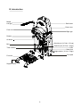
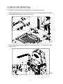
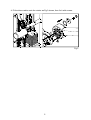
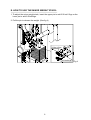
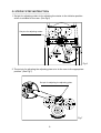
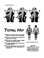
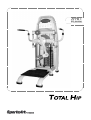
A961
OWNER'S MANUAL
ASSEMBLY INSTRUCTIONS
A. SAFETY INSTRUCTIONS
˙ Read all cautions/warnings and obtain proper instruction on use of the machines
prior to using. Use appropriate positioning and controlled movements.
˙ Assemble and operate the strength on a solid, level surface. Do not use outdoors
or near water.
˙ Never allow children on or near the strength.
˙ Make sure all fasteners are properly tightened for safety. DO NOT use the
strength if the unit is disassembled in any way.
˙ Keep head, limbs, and fingers clear of all moving parts.
˙ If at any time during exercise you feel faint, dizzy or experience pain, stop and
consult you physician.
˙ DO NOT wear loose or dangling clothing while using the equipment. Keep away
from all moving parts.
˙ Use care when mounting and dismounting the unit.
˙ DO NOT use any accessories that aren't specifically recommended by the
manufacturer. These might cause injuries or cause the unit to fall.
˙ Close supervision is necessary when this strength is used by, on, or near
adolescent, invalids, and disabled persons.
˙ Use this strength only for its intended use as described in this manual.
˙ Never operate this strength if it has been damaged in any way. If it is not working
properly, been dropped or damaged, contact your dealer. DO NOT attempt to fix a
broken or jammed machine. Notify floor staff.
˙ Never drop or insert any object into any opening.
1
B. Introduction
Badge
Left grip
Side frame
Rear cover
Front cover
Right grip
Rotator
Air shock
Selection pin (3.5 Lbs / 1.5 kgs)
Belt
Selection pin (6.5 Lbs / 3 kgs)
Cord
Stack fork
Tube cushion
Weight stacks (11 Lbs / 5 kgs)
Foot pad
Foot mat
Support frame
2
C. List of Parts
1. One side frame
2. One support frame
3. One tube cushion
4. One left grip
5. One right grip
6. Four hexagon head bolts, M10 x P1.5 x L30, for side frame and support frame
7. Four spring washers, M10, for side frame and support frame
8. Four hexagon hylon nut, M10 x P1.5, for side frame and support frame
9. Eight washers D16 x d10.2 x t1.0, for side frame and support frame
10. Six hexagon socket raised head bolts M8 x L20, for side frame and grips (R & L)
11. Six hexagon D18 x d8.5 x t2, for side frame and grips (R & L)
12. One double-end open wrench, 17mm x 23mm
13. One double-end open wrench, 8mm x 17mm
14. One hex key wrench, M6
15. One hex key wrench, M5
16. User's manual
3
D. STEP BY STEP INSTRUCTION:
1. It will be mush safer, when assembled by at least three persons.
2. While assembling, someone must hold the frame, and then tighten the support
frame and side frame by screws. (See Fig.1)
Fig.1
3. While assembling the grip, please fit the grip firstly (see
screws (see ).
) and then fix it with
Fig.2
4
4. Fit the tube cushion onto the rotator as Fig.3 shown, then fix it with screws.
Fig.3
5
E. HOW TO USE THE MINOR WEIGHT STACK:
1. To adjust the minor weight stack, insert the upper pin to add 3.5Lbs/1.5kgs or the
lower pin to add 6.5Lbs/3kgs.
2. Pull the pin to release the weight. (See fig.4)
(3.5Lbs/1.5Kgs)
(6.5Lbs/3Kgs)
6
Fig.4
F. BELT ADJUSTMENT:
1. If the belt is too tight or too loose, first loosen nut A as shown then adjust nut B. If
the belt length is too long , adjust downward; if the belt length is too short, adjust
upward. Adjust the belt to the proper position, then tighten nut A. (The gap
between nut A and B must be within 35mm. (See fig.5)
Fig.5
7
G. STEP BY STEP INSTRUCTION:
1. Set pin for adjusting rotator is for adjusting the rotator to the initiative position
which is suitable for the user. (See fig.6)
Set pins for adjusting rotator
Fig.6
2. The set pin for adjusting the adjusting plate is to tie the user to the appropriate
position. (See Fig.7)
Set pin for adjusting the adjusting plate
Fig.7
8
Usage Instruction:
9