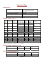
1
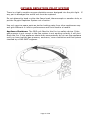
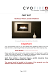
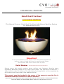
REV-6 [2010]
PIN NUMBER: 0063BL5590
TECHNICAL MANUAL
Small Oval Fire Bowl
[with MANUAL IGNITION]
This Manual Covers:- Small Oval Fire Bowl with Manual Ignition System
for Natural Gas or LPG
Important
It is recommended, even if you have fitted these appliances
before, that you take the time to read through these
instructions and follow them step by step.
Serial Number ………………………………
Please quote this serial number when calling our Customer Service team
regarding Warranty issues or to order spare parts. The warranty is valid for 1
Year from the date of delivery. The Warranty card supplied is to be completed by
the Installer and returned to the address below.
This manual must be handed to the owner of the property once the fire is
commissioned and retained for future reference.
Spirit Fires Ltd. Unit 4 Beaumont Square, Aycliffe Industrial Park, Newton Aycliffe, County Durham, DL5 6XN.
Tel: 01325 327221, Fax: 01325 327292, Email: [email protected], Web: www.cvo.co.uk
Contents
Page
Page
Page
Page
Page
Page
Page
Page
Page
Page
Page
Page
Page
Page
3
4
5
7
9
10
11
12
13
14
16
17
18
19
Technical Data
Unpacking the Appliance
General Requirements
Installation & Fitting Instructions
Commissioning the Fire
Completing the Installation
Final Install Checklist
Oxygen Depletion Pilot system
Spark Failure
Servicing Instructions
Replacement Components List
Fitting the Metal Control Knob
Fault Diagnosis
User Manual
WARNING:
THIS IS A GAS APPLIANCE AND IS COVERED BY CURRENT NATIONAL
REGULATIONS. ALL INSTALLATION WORK MUST BE COMPLETED BY A GAS
SAFE REGISTERED ENGINEER. CVO FIRE WILL NOT ACCEPT ANY CLAIMS
FOR DAMAGE OR WARRANTY ISSUES IF THE APPLIANCE HAS NOT BEEN
FULLY INSTALLED BY A GAS SAFE ENGINEER.
Page 2 of 28
Technical Data
Specifications
Gas Connection
NG: P4-10
NG: P4-10D (Holland Only)
LPG: P4-16
8mm O.D. Tube
Minimum Flue Diameter
178mm
Minimum Flue Height
3m
Approximate Weight
22kg
Pilot Burner Assembly Marking
Small Oval Gas Fire Unit
Gas
Type
Main Burner
Inlet
Injector Size
Category
Pressure (1
per
appliance)
Heat
Input
kW
Gross
Setting
Pressure
Country
(HIGH)
Mbar
NG
I2H
20
460
7.4
17.4
*95
9.5
15.4
NG
I2E+
20/25
460
*95
460
*95
460
7.4/7.0
9.5/8.8
7.4
9.5
7.0
17.4/21.7
15.4/19.1
17.4
15.4
21.7
NG
I2E
20
NG
I2L
25
*95
8.8
19.1
1.45
6.6
18.5
37
1.45
7.0
19.6
PROP
50
I3P
High Flame Picture
PROP
30
I3P
1.27
7.9
31.9
1.60
8.5
29.2
1.60
9.5
36.0
Small Flame Picture
PROP
30
I3P
PROP
PROP
I3P
I3P
37
Minimum Flue Diameter
Minimum Flue Height
AT, DK, ES, FI,
GB, IE, IT, PT,
SE
FR,BE
DE, LU
NL
NL
BE, ES, FR, GB,
IE, PT
AT, NL, DE
NL
BE, ES, FR, GB,
IE, PT
203 mm
1 mtr
* Refer to data plate for model which is being supplied.
Small Oval Bowl Dimensions (mm)
Model
Height
Depth
Width
Small Oval Fire Bowl Unit
195
330
490
Fire Opening Dimensions (mm)
Model
Max Height
Min Depth
Max Width
Enclosure Size
For Propane at 50mbar AT,
620
570
460
670
620
500
Page 3 of 28
NL, DE
Unpacking the Appliance
Read these instructions fully before proceeding
Carefully examine the carton for damage before unpacking. If it is obviously
damaged, consult the supplier over whether to proceed.
Remove the fire and examine its general condition. If satisfied by the condition
proceed with the installation. No claims for defects or damage will be accepted
once the bowl has started to be installed.
The installation should only be carried out by a Gas Safe Registered fitter and in
accordance with national and local Building Regulations. For the Republic of
Ireland, reference should be made to IS 813 and ICP3 and any guidance notes
from Bord Gais.
Failure to have the fire fitted by a qualified person will invalidate the
Warranty, and CVO Fire will not accept any claims for incorrect
installation.
Page 4 of 28
General Requirements
There are two versions of this fire - High and Low Power. Consult the data plate to
confirm the model supplied. This Small Oval Fire Bowl unit is intended for
decorative purposes. The installation must be in accordance with National
Regulations and must be carried out by a qualified installer. Clearances between
the fire and all combustible materials must conform to National Regulations.
This fire must be installed and used in accordance with these instructions. Prior to
installation, ensure that the local distribution conditions (identification of the type
of gas and pressure and the adjustment of the appliance) are compatible. The
builders opening or fireplace opening must be constructed of a non-combustible
material.
When installed, this unit should be located to the rear of the fire opening.
For some countries a non-combustible hearth must be fitted in front of the fire in
accordance with National Regulations (e.g. United Kingdom).
Any flue damper plate or flue restrictor must be removed or fixed permanently in a
fully open position, or shall only be fitted in accordance with National Regulations.
The chimney must be swept before the appliance is installed.
NOTE: If the chimney is not swept, there is a possibility that loose debris will fall
onto the appliance which may result in damage and unnecessary service costs.
Before the fire is installed a flue test in accordance with National Regulations
should be carried out. The unit must not be installed unless the chimney / flue
length is at least the length and size indicated in ‘Technical Data’.
Under no circumstances should this unit be installed and operated within any
premises without an adequate flue or chimney system.
The gas connection must be in accordance with National Regulations.
An isolation valve (or valves) has to be fitted adjacent to the appliance, which,
when closed allows the complete burner and control assembly to be disconnected
for maintenance and repair in accordance with national regulations.
The pilot light and flame sensing device fitted to this fire is also an atmosphere
sensing device. If for any reason any part of the pilot assembly is to be replaced
ALL the assembly including the pilot burner, thermocouple, electrode and injector
must be exchanged complete for an original manufacturer's pilot assembly only.
This atmosphere sensing device is not adjustable and must not be put out of
action. The pilot light shuts off both the main burner and pilot if evacuation of the
combustion products is interrupted. If the fire shuts itself off, do not use the fire,
and have the flue and fire checked by a suitably qualified person.
Page 5 of 28
For some countries a purpose provided air supply must be fitted in accordance
with National Regulations.
It is recommended that a guard be used for the protection of young children, the
elderly or infirm.
WARNING - OXYGEN DEPLETION PILOT SYSTEM
There is a highly sensitive oxygen depletion sensor designed into the pilot light. If
any part is damaged the entire unit must be replaced. The installer is advised not
to bend or alter the flame head, thermocouple or aeration hole, or put the Oxygen
Depletion System out of action. If any parts are exchanged, use only genuine
replacements, as spare parts as similar looking parts from other appliances may
well give different or inferior performance and could lead to a hazard.
WARNING – GAS SUPPLY
This is a high power appliance which needs a steady gas supply which can be
maintained at +/- 1mBar at all times. The gas inlet is via an 8mm isolation valve
fitted to the appliance. It is recommended that 22mm pipe work is used and
reduced down to 8mm as close to the appliance as possible. See “Commissioning
the Appliance”
ENCLOSURE AND FLUE SYSTEM
Enclosure: This appliance has been CE approved within an enclosure as specified
within the Technical section of this manual. If a customer designed enclosure is
used it must conform to the maximum and minimum requirements as specified.
Flue System: This appliance has been CE approved within a flue system of the size
and length as specified within the Technical section of this manual. If a flue system
is used which does not comply to this minimum requirement a flue spillage test
must be carried out to ensure the appliance operates safely.
APPLIANCE SHUTDOWN
If the points raised in the above sections “Gas supply” and “Enclosure and Flue
System” are not adhered to it is likely the safety device on the appliance will
operate and shut the fire down. This is not an appliance fault. This indicates an
Installation fault.
Page 6 of 28
Installation & Fitting Instructions
1.
The Gas Fire Bowl is supplied in an assembled state with an installation
booklet and a fitting kit. The bowl is either supplied with or without a
plinth.
2.
Before starting to install the bowl ensure that the enclosure, flue system
and gas supply conform to the minimum requirements of the appliance.
Only proceed if all items are correct and comply with the CE approval.
The room will require ventilation inline with current regulations.
3.
If a concealed gas connection is to be made, prepare the pipe work prior
to installing the inglenook and fitting the fire. It is advised to install
22mm gas pipe work as close t the appliance as possible with a reduction
down to 8mm at the inlet. This will ensure a steady gas supply.
4.
Although designed to be used in conjunction with the CVO range of
products, it is possible to use this unit with existing chimney systems and
alternative products. Where a new opening needs to be installed, its
minimum dimensions should be as specified.
5.
Ensure there is an 8mm gas supply at the point of installation. An inlet
pressure test point is supplied with the fire. This must be fitted in the line
as close to the isolation valve as possible. Failure to do this will give
incorrect gas pressure readings during installation and commissioning.
6.
Once the location is prepared, place the Fire Bowl to the rear of the
fireplace opening.
a. Without Plinth
i. Use a High Temperature Fire Cement to secure the bowl in the
desired position. It is advised this is done after connecting and
testing the fire. Once secured the bowl must be left for 24 hours
to allow the adhesive to dry before the customer operates the
fire.
ii. If using fire cement is not suitable then the burner can be
carefully removed from the bowl and the bowl secured in place
with screws and plugs. Review the section on removing the
burner unit within the “Servicing” section of this booklet. Once
the burner unit has been removed the plinth can be removed
and the bowl can be secured within the enclosure using the
screws and plugs provided. See Image 1.
b. With Plinth
i. The procedure is the same as without a plinth.
7.
Once fixed the bowl must not be able to move or “wobble” when
operated. Failure to fix the bowl within the enclosure will cause damage
to the burner and possibly gas leaks. No claims will be accepted for
damaged caused by “loose” fitting.
Page 7 of 28
8.
9.
Image 1:
Note: CVO recommend that the bowl is not dismantled as this can result in
damage not covered by the warranty. In most instances the bowl should be
secured using the plinth and silicone adhesive.
10. Fit the Gas Connection:
11. Ensure a suitable gas supply is available which can supply a
steady pressure in line with the technical requirements.
12. The gas inlet is from the rear of the bowl. The bowl is supplied with an
isolation valve and a pressure test point within the fitting kit. Remove the
rubber bung from the gas inlet pipe and fit the isolation valve. Cut a short
length o pipe and fit the inlet pressure test elbow.
13. The test point will be used when commissioning the fire. Connect the gas
supply pipe and check for gas soundness.
14. See the following section on how to commission the fire.
Page 8 of 28
Commissioning the Fire
DO NOT ADJUST THE FLOW RATES FOR THIS FIRE.
THESE ARE ADJUSTED AND SEALED AT THE FACTORY
Test the Gas Pressure.
This appliance requires a steady gas supply in order to function correctly and
safely. The gas pressure must be maintained within +/-1mBar of the stated
pressure shown on the Data Plate. For example in the UK – Natural Gas (20mBar)
should be within the range of 19 to 21 and LPG (37mBar) should be 36 to 38. The
results of the pressure and flue test should be recorded in the Commissioning
Table at the end of this section.
To Test the Gas Pressure:
1. The appliance is supplied with a pressure test point. This must be located as
close to the isolation valve as possible or incorrect readings will be taken.
2. Isolate the gas. Remove the test point screw and attach a manometer to the
inlet test point and open the isolation valve.
3. Review the section “lighting the fire” and light the fire.
4. Test 1: Turn “off” ALL the other gas appliances in the house.
a. Set the fire on the “maximum” (FULL) heat setting and check the Inlet
Pressure – Is the pressure within the required limits?
b. Set the fire on the “minimum” (LOW) heat setting and check the Inlet
Pressure – Is the pressure within the required limits?
5. Test 2: Turn “on” ALL the other gas appliances in the house.
a. Set the fire on the “maximum” (FULL) heat setting and check the Inlet
Pressure – Is the pressure within the required limits?
b. Set the fire on the “minimum” (LOW) heat setting and check the Inlet
Pressure – Is the pressure within the required limits?
c. Switch off the appliance and record the results in the “Commissioning
Results Table” on the next page.
6. Decide to proceed based on the results.
a. IF PASSED ALL PRESSURE TESTS:
i. Disconnect the pressure gauge then replace the pressure test
point sealing screw and test for gas soundness.
ii. Check the Flue as shown below.
b. IF FAILED ANY OF THE PRESSURE TESTS :
i. If the appliance fails any of the above pressure tests it must not
be used until either the gas pipe work to the appliance has been
improved or the governor to the house has been adjusted by
TRANSCO, BORD GAIS or the propane supplier.
ii. Running this type of appliance with incorrect gas pressure can
result in nuisance shutdown of the appliance or harmful
emissions being released into the room.
Test the Flue System.
The installer must check that all of the combustion products are entering the flue
after 10 minutes by traversing the perimeter of the fireplace using a smoke
(match). The flue system must be sealed to the gather and enclosure.
Page 9 of 28
Commissioning Results Table
The table below must be completed by the Gas Safe Engineer when commissioning
the fire.
TEST THE GAS PRESSURE
Test
Gas
Pressure
(mBar)
Pass/Fail
All Gas appliances in the home “OFF”
1
Fire Bowl Set on Maximum / High
2
Fire Bowl Set on Minimum / Low
All Gas appliances in the home “ON”
3
Fire Bowl Set on Maximum / High
4
Fire Bowl Set on Minimum / Low
TEST THE FLUE SYSTEM
5
Flue Size and Length as per Specification?
6
Purpose Provided Ventilation as per Regulations?
7
Smoke Test Completed on Flue System
ENGINEER DETAILS
8
Engineer Name
9
Gas Safe Registration Number
10 Company Name
11 Date of Commissioning
Note: for propane appliances, in order for the fire to operate consistently at
least 2 x 47Kg bottles must be used with a changeover valve to maintain the inlet
pressure at the required level as indicated on the data plate.
Completing the Installation
•
•
•
•
•
•
•
Brief the customer on the operation of the appliance.
The customer must be told of the need for regular servicing of the appliance,
this will be at least once a year, and be made aware that no rubbish is to be
thrown onto the fire bed.
The customer must also be aware that purpose provided ventilation should
be checked regularly.
Complete the Warranty Card and give this to the user.
Hand the instruction booklet to the customer.
If you have any questions about this appliance please contact CVO on
01325-327221 before leaving the installation.
If the appliance is not fitted in strict accordance with these instructions, CVO
cannot be held responsible for any damage caused and reserve the right to
charge for any corrective work.
Page 10 of 28
Final Installation Check List
•
•
•
•
•
•
•
Is the Gas Pressure Correct – all tests passed?
Is the bowl secure and cannot move?
Is the enclosure sealed to the chimney?
Has the Flue system been tested and the smoke test passed?
Dies the room have the required “free air” ventilation as per the
current regulations for this type of appliance?
Has the customer being shown how to operate the appliance?
Has the warranty card been completed and given to the customer?
If you have any questions, or the fire is not operating correctly, please
use the fault diagnosis charts above then contact the CVO Technical team
on 01325 327221 BEFORE you leave the installation. As part of our
Customer Service procedure you will be asked for the Fire Serial number
[on the front cover of the booklet] and Gas Safe Registration.
This manual must be handed to the owner of the
property once commissioned and retained for future
reference.
Page 11 of 28
OXYGEN DEPLETION PILOT SYSTEM
There is a highly sensitive oxygen depletion sensor designed into the pilot light. If
any part is damaged the entire unit must be replaced.
Do not attempt to bend or alter the flame head, thermocouple or aeration hole, or
put the Oxygen Depletion System out of action.
Use only genuine spare parts as similar looking parts from other appliances may
well give different or inferior performance and could lead to a hazard.
Appliance Shutdown: The ODS unit fitted to this fire is a safety device. If the
gas pressure is not correct or the flue system is not working correctly it will shut
down the fire. If the appliance shuts down unexpectedly do not use the appliance
until you have had the gas pressure, enclosure, room ventilation and flue system
checked by a GAS SAFE engineer.
Page 12 of 28
Spark Failure
The gap between the pilot electrode and the pilot should be 3.5 – 4.5mm and
normally adjustment is not necessary (the electrode is very brittle). The spark
should jump across the gap between the electrode and the gas outlet on the pilot
head. If the ignition fails, a lighted taper can be inserted into the pilot area to
check that gas is reaching the pilot.
Page 13 of 28
Servicing Instructions
The following servicing procedure should be carried out regularly and only by
a qualified person. CVO recommend that this appliance is serviced every
12 months.
Important: The pilot and flame sensing device fitted to this fire is also an
atmosphere sensing device. If for any reason any part of the pilot assembly is
to be replaced, the entire assembly including the pilot burner, thermocouple
electrode and injector must also be exchanged. This atmosphere sensing
device is not adjustable and must not be disabled.
How to Remove the Burner Unit
Prior to servicing the appliance the gas burner tray must be removed from the
outer Fire Bowl shell. Great care must be taken in handling the bowl as the
Ceramat is easily damaged. Once the Ceramat is damaged the burner unit
must be returned to the factory for repair. Any damage to the Ceramat is not
covered by the warranty.
The control knob must be removed, if he plastic version is fitted this can be
pulled off. If the metal control knob is fitted this must be removed first by
using the Allen key on the grub screw (see separate section).
Remove the burner tray by removing the two fixing screws located at the tips
of the burner tray, only remove these screws. After removing the burner place
the burner in a safe place.
Page 14 of 28
Servicing procedure
1. Turn off the fire and allow it to cool.
2. Turn off the gas supply at the isolation tap.
3. Disconnect the gas pipe from the valve.
4. Remove the 2 screws holding the burner tray into the bowl as shown in
the above section. Lift the burner tray clear of the bowl.
5. Taking great care not to damage the Ceramat matting clean any debris
from the pilot and also check the pilot has a good spark and sparks in the
correct area.
6. Remove and clean the injector. Do not use a needle or wire.
7. Re-assemble in the reverse order, and re-connect the gas supply.
8. Check for gas soundness.
9. Check that any purpose-provided ventilation is free from obstruction.
10. Re-commission the fire as described in ‘Commissioning the fire’.
Page 15 of 28
Replacement Components List
There are no user replacement parts on this gas fire. All repairs must be carried
out by a GAS SAFE engineer.
Part
Code
Item Description
Code
Number
Engineer
Parts
AC027
Gas Valve (See Note 1)
V4-28
Yes
AC009
Pilot Unit (NG)
P4-10
Yes
AC075
Pilot Unit (NG G25 ONLY)
P4-10D
Yes
AC007
Pilot Unit LPG
P4-16
Yes
AC026
Isolation Tap
B4-01
Yes
1.
2.
Injector (Call Customer Services)
Yes
Ceramic Matting Panel (See Note 2)
No
NOTE 1: Replacement Valve.
a. Replacement of the valve involves the use of a pressure gauge to set
the flow rates to the correct levels as shown in the technical section. If
the Engineer does not have the knowledge or equipment to do this the
bowl must be returned to the factory. See image below of valve.
NOTE 2: Replacement Matting.
a. Replacement of the matting is only possible at the factory.
b. The Burner unit must be removed from the bowl. Contact Customer
services on 01325-327221 and make arrangements for shipping and
payment.
c. Once repaired and retested the burner will be returned for fitting back
into the bowl.
Page 16 of 28
Fitting the Metal Control Knob
See Image Above.
The metal CVO gas control knob is fixed in position on the gas valve shaft by
means of a 4mm grub screw. The grub screw, when tightened, should clamp
against the flat face on the shaft.
When fixed correctly, the CVO logo should be horizontal, with the arrow
pointing to the base of the unit.
Ensure the control knob is securely fitted to the shaft to avoid ignition problems
for the user.
Page 17 of 28
Fault Diagnosis
Symptom
Unit clicks but no
spark or weak
spark.
Unit sparks but
does not light pilot.
If there is no gas.
Check List
Check spark lead is connected properly.
Check spark electrode is in the correct area and the gap
correctly distanced.
Check for a good spark.
Check the spark is in the right area.
Check that the ventilation is not too strong and the flame
is not blowing off the thermocouple.
Check if there is gas running through.
Check gas working pressure is correct: NG-20mBar, LPG
37mBar
Check isolation tap/shut off valves are free from grease.
Check isolation tap/shut off valve are on.
Check for blockages
If there is gas but
pilot does not light
Check gas working pressure is correct :NG-20mBar, LPG37mBar
Check for blockages in pipes.
Check for draughts which can reduce pilot flame.
Check the pilot gas slot is clear of debris.
Pilot lights but
does not light main
burner
Burner lights but
turns off after a
few minutes
Check the pilot flame is heating the thermocouple and
there is a draft shield fitted if required.
Check the thermocouple nut is properly tightened into
the valve/interrupter block.
Check that the pilot lights early on ignition clicks.
Check ventilation is not too strong and the flame is not
blowing off the thermocouple.
Check gas working pressure is correct : NG-20mBar,LPG
37mBar.
Check thermocouple nut is properly secured to the
interrupter block on the valve.
Check ventilation is not too strong and the flame is not
blowing off the thermocouple.
Check working gas pressure is correct :NG-20mbar, LPG37mBar.
Page 18 of 28
Tick
GAS FIRE USER MANUAL
Small Oval Fire Bowl
[with MANUAL IGNITION]
This Manual Covers:- Small Oval Fire Bowl with Manual Ignition System
for Natural Gas or LPG
Please quote the serial number as shown on the front of this booklet when
calling our Customer Service team regarding Warranty issues or to order spare
parts.
The warranty is valid for 1 Year from the date of delivery. The warranty covers
defective components and does not cover incorrect installation or wear and tear.
The Warranty card supplied is to be completed by the Installer and returned to
the address below.
Page 19 of 28
Contents
Page
Page
Page
Page
Page
Page
21
22
24
25
26
28
General Information
Lighting the Fire
Cleaning Instructions
Warning Fire Guards
Warranty Information
Contact Details
Page 20 of 28
General Information
A qualified GAS SAFE registered installer is required to fully install the appliance,
failure to do this may render the appliance dangerous and will invalidate the
warranty.
This fire is intended for decorative purposes. Any purpose-provided ventilation
should be checked regularly to ensure that it is free from obstruction. The fire
should be serviced regularly by a qualified person.
The chimney should be swept before the appliance is installed, and should be
swept and inspected regularly to ensure that all of the products of combustion are
entering the flue and there is no excessive build up of soot.
Do not throw rubbish et cetera upon the burner surface. Debris from any source,
or soot formed, should be removed from time to time, see ‘Cleaning instructions’.
If any of its parts are damaged and need to be exchanged the original
manufacturers parts must be used.
Pilot Assembly: The pilot light and flame sensing device fitted to this fire is also
an atmosphere sensing device, which shuts off both the main burner and pilot if
evacuation of the combustion products is interrupted. If the fire shuts itself off,
restart the fire following the procedure in section ‘Lighting the fire’. If the fire
continues to shut itself off do not use the fire, and have the flue and fire checked
by a suitably qualified person. The pilots ODS (Oxygen depletion sensor) must not
be put out of operation. The user must not adjust the pilot.
Once the flue and fire units have been checked and remedial action taken, the fire
is ignited in the manner depicted in section ‘Lighting the fire’.
Due to the newness of materials, the fire may give off a slight smell for a period of
time after commissioning. This is quite normal and any odours should disperse
within a few hours of operation.
For some countries a purpose provided air supply must be fitted in accordance
with National Regulations.
This fire should be serviced every 12 months by a qualified engineer to ensure that
it is working correctly and the flue is free from obstruction.
Fire Guards: It is recommended that a fireguard conforming to BS6539 or
BS6778 is used for the protection of young children, the elderly and infirm.
Noise: The low rate on the burner unit has a running noise level due to the nature
of the gas flow through the valve. This is normal for this size of fire.
Page 21 of 28
Lighting the Fire
The positions of the control valve are depicted on the control panel fitted
around the control knob.
If the main burner or pilot light are extinguished for any reason, do not
attempt to relight the pilot within 3 minutes.
The OFF position is self-explanatory - preventing any gas from passing
through the control valve to either the pilot burner or to the main burner.
By pressing the control knob in, it is possible to turn it anti-clockwise.
The first function is to turn on the gas to the pilot - this occurs just before
reaching the PILOT position. (If the fire has not been lit for some time it
may be necessary to hold the knob in this position for some seconds to clear
the air from the pipe and allow gas to reach the pilot burner). Once gas is
available at the pilot, continued rotation (anti-clockwise) will cause the piezo
igniter to spark. This is accompanied by a click at the valve and should
result in the pilot burner igniting. This can be verified by looking at the rear
central section of the burner unit.
Once the pilot is lit, the control knob should be pressed in and held for 1012 seconds. In this time the pilot flame will have heated the flame
supervision thermocouple sufficiently to operate a hold-on magnet within
the valve. The knob should then be turned so that the pointer is
approximately horizontal. This allows gas at a low rate to enter the burner
and be ignited by the pilot flame. Once ignition has taken place, the fire may
be set to any level between MAX and MIN by rotating the control knob
accordingly.
To turn off the main burner, turn the control to MIN - press the knob in
gently and turn it clockwise to the PILOT position. To turn off the pilot, press
knob and turn to OFF.
Page 22 of 28
Thus the sequence is:
To Light:
From OFF press the control knob in and turn slowly anti-clockwise.
When the ignition click occurs, check that the pilot is lit. (If not repeat steps
1 and 2)
Step 1:
Hold the knob in for 10 -12 seconds.
Step 2:
Release knob and check pilot remains alight.
Step 3:
Turn knob until pointer is horizontal, the fire should then ignite.
Adjust flames to required level without pressing the knob.
To Extinguish:
Turn control knob clockwise to MIN position.
Press knob gently until able to continue turning clockwise to PILOT.
To extinguish the pilot press knob and turn to OFF, although the pilot can be
left permanently lit, if required.
Page 23 of 28
Cleaning the Gas Fire Matting
WARNING: Under no circumstances must the matting be brushed, touched or
hovered. If the matting is damaged in anyway the bowl will need to be returned to
the factory for repair. This damage is not covered by the warranty.
Due to the surface area and flatness of the ceramic burner matting, it is inevitable
that dust, debris from the chimney and combustion by-products will accumulate;
Under most circumstances dust etc will burn off when the bowl is used. Large
pieces can be carefully picked from the matting with tweezers. Make sure the
matting is not disturbed.
Cleaning the Stone Bowl
Once installed, the unit should be dusted periodically to remove naturally
collecting dust particles from its surfaces - this can be done using a soft brush.
Removing spillages
If any liquids are spilt on this appliance under no circumstances use the appliance.
Contact your installer to check the fire bowl and ensure it still operates safely.
Damage from Wax
Under no circumstances must candles be placed on the matting surface. If wax is
allowed to accumulate on the matting the fire bowl should not be used. Contact
customer services on 01325-327221 to arrange for the return of the fire bowl for
replacement of the matting. This damage is not covered by the warranty.
Cleaning bronze or aluminium fire bowl
Metalwork can be kept clean by simply dusting or wiping with a damp cloth. Where
the metalwork has become tarnished by finger marks etc, a highly polished finish
can achieved using a cloth and a propriety cleaning fluid like Brasso.
Page 24 of 28
WARNING: FIRE GUARDS
This appliance is not fitted with an integral guard. In normal use
consideration may be given to the use of a fireguard conforming to
BS6539 or BS6778, so that the approach to the appliance is limited such
that access to the flame is minimised
It is recommended that a fireguard conforming to BS6539 or BS6778 be used for
the protection of young children, the elderly and infirm.
The installer is to advise the user not to stand too close to the appliance for
prolonged periods of time and warn that loose clothing is particularly at risk of
burning due to the presence of an unguarded flame.
In addition, the installer is to advise the user against placing combustible material
directly in front of the appliance. Floor coverings, such as carpets, are considered
to be acceptable.
Hearths
For some countries a non-combustible hearth must be fitted in front of the fire in
accordance with National Regulations (e.g. United Kingdom).
Metal Cast Bowls
Bowls which are manufactured from Cast Metal are sand cast at a UK Foundry and
then Hand Polished for over 15 Hours at the CVO Fire Factory. Pitting and Air
Holes are a normal occurrence and are a part of the unique quality of such a hand
made piece. All Bowls are inspected and given a full quality control check at the
factory. If the Bowl supplied includes Pitting and Air Holes this will have passed the
in-house inspection and cannot be used to form a Warranty claim. We hope that
you will see that the overall beauty and uniqueness of your CVO Fire outweighs
what is a very minor feature.
Page 25 of 28
WARRANTY INFORMATION
If the appliance develops a fault please refer to the fault diagnosis section earlier
in this booklet for possible causes. Most faults can be rectified by giving the
appliance a service. The appliance has a safety device to warn of low gas pressure
and blocked flue. Recall your installer to check the site conditions before
considering the appliance faulty.
To register your appliance please complete and return the warranty card supplied
with the fire.
Period: This appliance is supplied with a 12 month warranty from the date of
delivery.
Wear and Tear: The warranty covers defective parts and does not cover typical
wear and tear that occurs with a gas fire appliance. Items not covered by the
warranty include tarnishing, soot or heat damage of any kind.
Fire Bowl Matting: Any damage to the matting surface other than damage
notified on the day of delivery will also not be accepted. The matting is very hard
wearing and will last the lifetime of the product. Damage only occurs when the
matting is cleaned or touched.
Requirements:
To raise a warranty claim call Customer Service on 01325-327221.
In order to make a warranty claim you will be required to supply the
following information. We cannot process any warranty claims unless the
information provided is complete.
• The Gas Safe registration number of the Gas Engineer who installed and
commissioned the fire.
• The Serial Number of the appliance as shown on the front of this book.
• A Copy of the Installation Receipt
• A Copy of the completed “Commissioning Results Table” as shown earlier
in this booklet.
Failure to supply details required will invalidate the warranty and we reserve the
right to charge for any remedial work required including all labour and material
costs.
Page 26 of 28
Page 27 of 28
ONLY USE GENUINE REPLACEMENT PARTS
To order Spare Parts please contact Customer Services on 01325 327221. Opening
hours are 9.15am to 3.15pm Monday to Friday.
For further Technical information please call our CVO Technical
Department on 01325 327221.
Spirit Fires Ltd.
Unit 4 Beaumont Square,
Aycliffe Industrial Park,
Newton Aycliffe,
County Durham,
DL5 6XN.
Tel: 01325 327221,
Fax: 01325 327292,
Email: [email protected],
Web: www.cvo.co.uk
The following information supplied in this manual is correct at
the time of publish; Updated on the 07-10-09. There may be
changes made in future as we improve our products. If there
are any queries please write or call our Technical Department.
Page 28 of 28