1
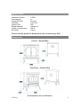
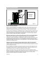
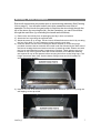
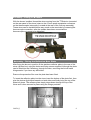
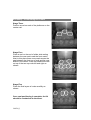
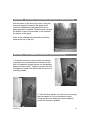
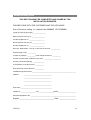
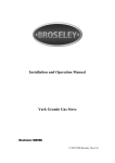
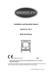
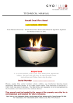
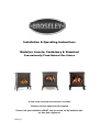
Installation & Operating Instructions
Model(s): Lincoln, Canterbury & Stamford
Conventionally Flued Natural Gas Stoves
PLEASE LEAVE THESE INSTRUCTIONS WITH THE USER
Chimney closure plates are not supplied
Please note gas installations MUST only be carried out by installers who
are Gas Safe registered.
200704_3
Contents
Introduction
Packing List
Specification
Dimensions
3
3
4
4
Hearth Requirements
Chimney Requirements
5
6
Assembly
Burner Installation
Connecting the TTB Device and Fitting the Reflective Rear Plate
Positioning the Coals
Gas Connection & Pressure Testing
7
8
9
10
Spillage Testing
13
Operating the Stove
14
Curing the Paint
Trouble-shooting
15
16
Servicing Instructions
Commissioning Form
Guarantee
17
18
19
200704_3
2
Introduction
THANK YOU FOR PURCHASING A BROSELEY GAS FIRED STOVE
Broseley Fires Ltd, a family run company, was founded as an appliance and
design development company in 1975.
Since then we have built up an enviable reputation for the quality, reliability and
fuel efficiency of our stoves.
These instructions have been carefully prepared to guide the installer and enduser through the relevant methods and standards for installation of your new Gas
Stove.
Correctly installed and operated, your stove will give you many years of warmth
and reliability. Therefore, we would suggest that you read the whole instruction
manual prior to handing it to your installer. That way you will have a clearer
picture of what is involved.
It is required by law that the complete assembly, installation and commissioning
of gas-fired stoves is carried out by a professionally qualified and accredited gas
fitter listed on the “Gas Safe” register.
THE INSTALLATION MUST BE IN ACCORDANCE WITH THE ‘GAS SAFETY
INSTALLATION AND USE REGULATIONS’ IN CONJUNCTION WITH THESE
INSTRUCTIONS AND THE RELEVANT ‘BRITISH STANDARDS CODES OF
PRACTICE’ REQUIREMENTS AND THE RELEVANT ‘LOCAL AND NATIONAL
BUILDING REGULATIONS’. A COMMISSIONING CERTIFICATE MUST BE
LEFT WITH THE END CUSTOMER UPON FINAL COMPLETION AND THE
COMMISSIONING FORM COMPLETED IN THE BACK OF THESE
INSTRUCTIONS.
Packing List
Burner Box
1 x Burner unit
1 x Stainless reflector Plate
2 x Large coal matrix
4 x Small front coals
14 x Small loose coals
1 x Instruction booklet
4 x Burner fixing and screws
Stove Box
1 x Cast iron stove body
4 x Legs & bolts
1 x Flue spigot
Canterbury Only
1 x Handle (inc Allen bolt and grub screw)
(2 x Self Tapping to hold to the rear of the stove)
2 x Spacers for burner
3 x Self Tapping Screws (for the reflector plate)
4 x Self tapping screws (for spigot connection)
4 x Washers
200704_3
3
Specification
Heat Input (Gross)
Gas Category
Supply Pressure
Gas Rate
Injector Size
Spigot diameter
Country of destination
Efficiency
5.5kW
I2H
20 mbar
0.66 m3/hr
360
125mm (5”)
GB, IE
Class 1
Please note this product is designed to only use natural gas G20.
Dimensions
Lincoln – Weight 64Kg
Canterbury – Weight 66Kg
All dimensions are in millimetres.
200704_3
4
Hearth Requirements
The appliance needs to be located onto a solid non-combustible hearth with a
minimum thickness of 12mm. The hearth must be capable of withstanding the
weight of the appliance.
To ensure correct combustion the following minimum clearances must be
adhered to:
Inglenook Installation
Stove Clearances
Non-Combustible
Combustible
Freestanding Installation
A
25mm
N/A
B
75mm
610mm
C
50mm
610mm
Above
100mm
610mm
Please note these are minimum clearances, whenever possible it is advisable to
have as much clearance as possible around the stove for easy access and
maintenance.
Please note the gas supply connection to the appliance is in the centre
underneath the stove. The connection requires an 8mm-diameter semi-rigid
pipe, not more than 1 meter in length.
200704_3
5
Chimney Requirements
D
Lintel
Dimensions
B
A = 250mm Min.
B= 50mm Min.
C = 50mm Min.
D = 25mm Min.
Void
Closure
Plate
C
A
Figure 1
Class 1 Chimney Example
Above is a typical example of an installation with a class 1 flue, please note we do not
supply chimney closure plates. The appliance can be installed in any adequate area
suitable for solid fuel fires and stoves. It can use a class 1, class 2 and pre-cast flue.
For pre-cast flue installations it is ESSENTIAL that a sealed connection is made into the
actual flue system (a void behind the closure plate is not permitted). Please refer to the
codes of best practice for further advice on pre-cast flue’s. The 150mm pipe supplied
can be cut down in length but CANNOT be extended.
Before you install the stove, make sure the chimney flue outlet is correctly positioned to
align with the flue outlet on the stove and that the chimney is in good condition. If not, a
chimney liner must be installed or a suitable class II gas flue used. A draught is
necessary to ensure the products of combustion are fully evacuated. Due to the internal
dilution/diversion system in the stove, it is not obligatory to line the chimney but local
conditions will apply. The flue will have to be inspected by a Gas Safe registered installer
and passed as suitable/sound.
Ideally it is recommended that a minimum height of 610mm from the stove should be
established before any significant changes of the direction of the flue. Horizontal or
negative gradients should be avoided. The flue must have a minimum height of 3 metres
to insure adequate draught.
Prior to installation, the installer should insure that the flue is free from obstruction and
any dampers must be fixed in a permanently open position. Ensure the chimney is not
closed and that it has been swept and subsequently smoke tested.
Make sure that rain, birds or any foreign body cannot get into the chimney to cause
damage or blockage. This problem can normally be overcome by fitting an approved gas
cowl. It is essential for the effective running of your stove that the chimney draws
properly to allow the products of combustion to escape.
200704_3
6
Assembly - Burner Installation
Ensure all components are present prior to commencing assembly (See Packing
List on page 3). You will need a short pozi-drive screwdriver and a set of
spanners. On the Lincoln the gas burner is fitted into the stove body through the
top of the stove (by removing the lid). On the Canterbury you can fit the burner
through the main door (by unwinding the handle anti clockwise).
1) Remove the stove body from its packaging and lay it down on its back.
2) Attach the four legs using the supplied bolts.
3) Stand the stove up on its legs. On the Lincoln & Stamford remove the lid by un-doing
the four fixing bolts. For the Canterbury simply open the main door.
4) Insert the burner into the stove locating the burner bracket on to the fixing lugs
provided. Insert the burner end with the control knob first followed by the other end of
the burner locating the burner bracket onto the up stands provided. Please note with
the Lincoln and Stamford models 2 spacers are required. These spacers are to be
located on top of the lugs and under the burner brackets (2 off additional washers
are required on top of the spacers before securing the burner to the fixing lugs). The
longer screws are then used. Use the burner fixing screws and 2 off washers to
secure the burner in place.
5) Next fix the rear of the burner bracket to the rear of the stove (dilution box) using the
self tapping screws provided.
200704_3
7
Assembly - Fitting TTB sensor
With the burner installed, thread the wires running from the TTB device (mounted
on the rear panel of the stove) down to the 6.3mm spade receptacle connectors
on the thermocouple interrupter (Located at the rear of the Gas top assembly),
These wires can be installed either way round on the terminals by loosening the
thermocouple connection, after the spades have been connected the
thermocouple nut needs to be tightened.
Assembly - Fitting the Reflective Rear Plate
After fixing the burner in position fit the stainless reflector plate to the rear of the
stove (dilution box) using the holes and fixing screws supplied. Although the plate
can be fitted into the Canterbury through the door, removing the lid will make
things easier if you have any difficulties.
Remove the protective film once the plate has been fitted.
To insert the reflective plate into the stove insert the bottom of the plate first, then
give the plate a slight bend inwards on both sides and finally bring the top of the
plate into place. The reflector plate simply drops down through the top of the
stove and is then secured in place using the fixings provided.
200704_3
8
Flue Spigot Connection
Attach the supplied 150mm long flue spigot to the rear of the stove using the four
self tapping screws provided.
Assembly - Positioning the Coals
Only the ceramics supplied with this appliance should be used. The ceramics
should only be laid as described. Before any ceramics are placed in position
ensure that the pilot is not obstructed and the burner is operating correctly.
Broseley Fires Ltd accepts no responsibility for any injury sustained whilst
handling hot ceramics. Ceramics which are found to be placed other than in
accordance with these instructions will result in a charge being made following
any service callout. Replacement ceramics are available from your dealer.
Stage One
Position the two large coal matrixes on the
burner, on the Lincoln & Stamford Model only,
ensure that the clearance between the Front
Matrix ports and the front of the Rear Matrix is
15mm as measured from the centre of the Rear
Matrix.
Stage Two
Position the four separately packed coals in the
corresponding indentations on the front edge of
the coal bed. These 4 coals are larger and have
a flat area on one side which should be position
in the four indentations in the coal bed.
200704_3
9
Assembly - Positioning the Coals
Stage Three
Position a coal on each of the platforms on the
centre coal.
Stage Four
Place a coal on the end of either side resting
between the rear matrix and the front matrix.
Next to this place three more coals across the
gap between the front row of coal and the rear
matrix in the centre. Place two additional coals
on top of the two top coals left and right as
shown.
Stage Five
Place the final layers of coals carefully as
shown.
Once coal positioning is complete, the lid
should be re-attached to the stove.
200704_3
10
Assembly – Decorative Log Retainer (Lincoln & Stamford Only)
With the doors of the stove fully open, Using the
recesses supplied forward of the glass panel
locate the castellation plate taking care not to
damage/scratch the glass. Slide the plate towards
the bottom of the unit and locate in the recess at
the bottom of the glass.
Note: Once installed the castellation should be
towards the top of the unit.
Assembly – Door Handle Installation (Canterbury Only)
1. Push the stove door closed, place the washer
(supplied) over the threaded rod followed by the
hex nut (supplied) tighten the hex nut and washer
against the stove door. Tighten to ensure the door
is sealed and make sure that the flat on the nut is
vertically parallel.
2. Slide the door handle over the hex nut ensuring
that the handle is in the downwards position.
Using the allen key and grub screw (supplied)
secure the handle in position.
200704_3
11
Assembly - Gas Connection & Pressure Testing
A minimum 15mm-diameter gas supply pipe must be used to within 1 metre of
the installation with the final connection to the stove to be completed with the
suitable 8mm semi-rigid gas pipe. The 8mm pipe should be connected to the inlet
of the gas valve using the nut and 8mm olive provided. Support the control whilst
finally tightening the supply pipe.
The gas supply connection to the appliance is in the centre underneath the stove.
The connection requires an 8mm-diameter semi-rigid pipe, not more than 1
meter in length.
Pressure Testing
Always make sure that there is adequate gas pressure and volume to the stove.
The relevant pressures are on the ID plate on the gas control knob.
1. For natural gas, this is 20mbar measured at the inlet connection to the
stove with the appliance in the full rate position.
2. Ensure that the gas pressure to the stove is maintained when it is
operating at the same time as other appliances in the building and that a
suitable pressure gauge is used i.e. a manometer. Any service call as a
result of incorrect gas pressure will be chargeable.
Ventilation (GB only)
The gas stove is rated at less than 7kw and therefore does not normally require
additional ventilation in the room (BS5871 – part II).
200704_3
12
Spillage Testing
A Spillage Test MUST be made before the installed fire is left with the customer.
Carry out the test by first closing all doors and windows in the room containing
the fire.
Insure that the fire is burning at full rate for a minimum of 10-15 minutes.
Using a lighted smoke match, run it along under the rear edge of the stove. The
draught diverter box is situated at the rear of the stove, the entry being in the rear
panel for the stove. Observe the smoke being drawn into the dilution box. After
10 minutes repeat the test
If there is an extractor fan in a nearby room the spillage test must be repeated
with the fan running and all connecting doors between the fire and fan left open.
If there are still problems, the chimney / flue may require attention. Disconnect
the stove and seek expect advice.
Spillage Monitoring System
This appliance is fitted with an atmospheric sensing spillage monitoring system,
in the form of an oxygen depletion-sensing pilot. This is designed to shut down
the fire within a safe period if there is an excessive build up of products of
combustion within the room space. This would usually only occur if the flue path
suffered severe blockage and / or ventilation was severely impeded.
THE FOLLOWING ARE IMPORTANANT WARNINGS RELATIVE TO THE
SPILLAGE MONITORING SYSTEM
1. The installer must not attempt any adjustments to the spillage monitoring
system.
2. There must be no attempt to disable the spillage monitoring system.
3. It is not possible to replace individual parts of the pilot assembly on the
appliance – only a complete pilot assembly (including thermocouple) may
be fitted in the event of a replacement being necessary. When the
spillage monitoring system is replaced, only complete and original
manufactures’ parts may be fitted.
4. Should the appliance turn itself off, wait for a minimum of 3 minutes before
attempting to re-light. In the event of your stove tripping out, consult your
installation engineer to have the flue / chimney checked.
200704_3
13
Operating the Stove
It is important to read these instructions thoroughly before lighting the
stove.
The gas stove operates with a traditional permanent pilot light.
The knob for ignition and power control are located on the lower right hand side
of the stove, the indicator in the plate shows the knob position (Marked on knob)
The pilot light is located at the left corner of the coal matrix.
If the Flame Supervision Device Actuating Flame (the pilot light) is extinguished
by intention or not, no attempt should be made to re-light until 3 minutes have
elapsed.
IGNITING THE PILOT AND USING THE HIGH/LOW FUNCTION
1. Depress the control knob fully.
2. Whilst depressed, turn knob sharply 90 degrees anti-clockwise to “pilot”
setting. Repeat until pilot light is visibly lit. You should feel some
resistance and hear a click. Repeat until the pilot lights.
3. Keep knob depressed at this point for 15-20 seconds.
4. Upon releasing, turn the knob Anti-clockwise to select the low flame
setting. Turning the control further anti-clockwise you will be able to select
the high flame setting.
5. From the high setting you can select low by depressing the control slightly
and turning clockwise
EXTINGUISHING THE STOVE FULLY
1. From any heat setting or the permanent pilot, depress control knob and
turn clockwise to “OFF” position.
Should the glass door become broken or damaged in any way, turn your stove
off and do not attempt to re-light it. Contact your dealer for a replacement to be
fitted before relighting the appliance.
PLEASE EXPLAIN TO THE CUSTOMER THESE LIGHTING AND
EXTINGUSIHING PROCEDURES AND THAT IT IS NORMAL FOR THE
STOVE TO GIVE OFF ODOURS WHILST THE PAINT, SEALANT AND CAST
IRON MATURES.
200704_3
14
Curing the Paint
It is important to note that upon initial lighting of the stove you will notice a strong
odour, this is the paint curing and is completely normal.
Most high temperature paints operate in the same way. They use a resin which
dries at room temperature and a silicon resin which cures at high temperatures.
When the stove is burned the dry resin burns away and the silicon cures. This
transition occurs about 240 degrees C / 475 degrees F.
After the stove burns about three times, the entire surface which gets hot will
have cured. The house needs to be fully ventilated during these initial burnings
and although the smoke is mostly Carbon Dioxide there are other components of
the smoke which make it smell bad and may irritate some people. These
problems will go away after the first few burns depending of the duration and
surface temperature of each burn. The hotter the stoves gets the more it will
cure.
200704_3
15
Trouble-shooting
The gas pilot will not ignite or stay lit
• Ensure the gas is turned on at the appliance and the meter / cylinder.
• Hold the pilot gas button for at lest 20 seconds once the pilot is alight to
ensure the operation of the safety thermocouple valve.
• Ensure that the connections from the TTB to the rear of the valve assembly
are connected. If these are not connected then the burner will not light.
• Ensure that the pilot injector is not obstructed or blocked and it is free from
any dust or dirt.
• Ensure that the thermocouple has not been damaged in transit. This is a very
delicate device.
• Ensure the pilot flame is the correct size for the type of gas. The flame should
be focused on the thermocouple probe, so that it is evenly encircled.
• Any whistling sound you hear is normally caused by dirt obstructing the pilot.
This is normally cured by carrying out the cleaning process outlined in the
next section entitled Servicing Instructions.
• After altering the pilot, check for any leakage of gas
The main burner does not seem to burn correctly
• Ensure there is adequate gas pressure to the appliance. The pressure can be
obtained by unscrewing the pressure test nipple and applying a suitable
pressure gauge (I.E. A MANOMETER). Be sure that the gas pressure agrees
with the identification label on your stove.
• Ensure adequate volume of gas is being used. Once the fire is burning on
maximum turn off all other gas appliances in the house and calculate the fuel
being burned from the gas meter
• See that the burner is burning evenly across the whole of the burner surface
without any coals in place.
200704_3
16
Servicing Instructions
Servicing should be carried out annually by a qualified installation engineer when
the stove is cold and the gas supply is turned off at the isolation tap. The
following points should be checked.
•
•
•
•
•
•
Remove the coals and clean any dust and debris from the top of the burner
unit. Ideally a vacuum cleaner should be used, but a soft brush will do.
Check the condition of the coals. Any damaged ones will affect the efficient
operation of the stove and should be replaced with new ones available from
your stove supplier.
All gas supply joints should be checked to make sure they are completely
sealed and that the gas supply and pressure is to specification.
The pilot jets are correctly set and clear of obstruction.
The chimney should also be checked to make sure there are no restrictions or
blockages.
Finally re-lay the coals and re-light the stove as described previously.
200704_3
17
Commissioning Form
THIS SECTION MUST BE COMPLETED AND SIGNED BY THE
INSTALLATION ENGINEER
PLEASE LEAVE WITH THE CUSTOMER AND THE APPLIANCE.
Size of Governor setting: (i.e.) Natural Gas 20MBAR. LPG 37MBAR)
Length and size of gas supply: _______________
Meter pressure Fire only on: ________________
All Other appliances on: __________________
Burner pressure Fire only on: _______________
All Other appliances on: __________________
Gas rate - Natural Gas - Time for 1 cubic foot in seconds: ___________
Overall length of flue: __________
Is there any spillage: __________Is the draught excessive: __________
Is there any permanent ventilation in the room: ____________________
Has the room double glazing: ______________
Is the aeration of the pilot correct: __________
Does the flame encircle the FFD: ___________
Installation Engineers Name: _____________________________________________________
Address
__________________________________
__________________________________
__________________________________
__________________________________
Post Code: ______________________________________
Telephone: __________________ Fax:__________________Mobile:______________________
Gas Safe Registration No: _______________________________________________________
Signed: ___________________________________ Date: _________________
200704_3
18
Guarantee
Your decorative gas fire, when installed in accordance with the installation
instructions and operated in accordance with these instructions should provide
many years of safe and efficient operation.
We thank you for purchasing our product and trust it will provide excellent
service.
This appliance carries a guarantee of One (1) Year.
We agree to repair free of charge or, at our option, replace the appliance or part
thereof, which may prove to be defective within the guarantee period.
The guarantee is void if:
•
•
•
•
•
•
The appliance is not installed and operated in accordance with our
instructions, or
Repairs or modifications have been carried out by the purchaser or any third
party not authorised by us or:
The appliance has been misused or accidentally damaged, or
Damage is due to ‘fair wear and tear.’ or
The appliance or defective component(s) are not returned to us, prepaid
postage.
The appliance has not been serviced annually by a ‘Gas Safe Registered’
engineer.
The rights given in this guarantee are limited to the UK mainland and are in
addition to any to which you may have a statutory entitlement.
Please retain your purchase receipt. We will need to see this in the event of a
claim under warranty.
Broseley Fires Ltd
Knights Way
Battlefield Enterprise Park
Shrewsbury
Shropshire
SY1 3AB
Tel: 01743 461444
Fax: 01743 461446
http://www.broseleyfires.com
200704_3
19