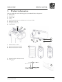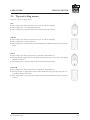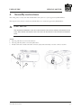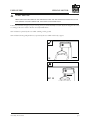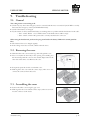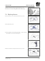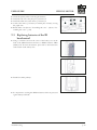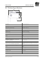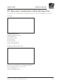
1
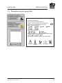
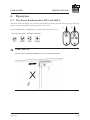
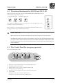
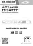
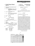
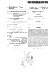
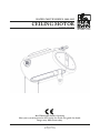
HANDI-MOVE MODEL 2800-2815 ceiling motor User guide Read Thoroughly Before Operating Have your system inspected at least yearly. See inside user guide for details. Images may differ from reality. V 1.3 - 30-07-2015 © Handi-Move All rights reserved User guide ceiling motor Table of contents 1. Safety instructions ....................................................................................................................................... 3 2. Scope of application..................................................................................................................................... 5 3. Product information..................................................................................................................................... 6 3.1. Types of ceiling motors..................................................................................................................... 7 4. Assembly instructions.................................................................................................................................. 8 5. Explanation of the symbols........................................................................................................................ 10 5.1.Control............................................................................................................................................ 10 5.2. Symbols on the nameplate and packaging...................................................................................... 10 5.3. Nameplate and packaging label...................................................................................................... 11 6.Operation................................................................................................................................................... 12 6.1. The electric handcontrol for 2815 and 2810 L............................................................................... 12 6.2. The infrared handcontrol for 2805 IR and 2815 L IR................................................................... 13 6.3. The Control Panel (for emergency operation)................................................................................ 13 6.4.Functions......................................................................................................................................... 14 7. 6.5. Charging the batteries..................................................................................................................... 15 6.6. Automatically stopping the Ceiling Motor at a specified location................................................. 15 6.7. IR handcontrol................................................................................................................................ 15 Maintenance and storage space.................................................................................................................. 16 7.1. Cleaning the ceiling motor............................................................................................................. 16 7.2. Storing the ceiling motor................................................................................................................ 16 8.Inspection .................................................................................................................................................. 17 8.1. Inspection before each use.............................................................................................................. 17 8.2. Yearly Inspection............................................................................................................................. 17 9.Troubleshooting......................................................................................................................................... 18 9.1.General........................................................................................................................................... 18 9.2. Removing the cover........................................................................................................................ 18 9.3. Assembling the cover...................................................................................................................... 18 9.4. Replacing batteries.......................................................................................................................... 19 9.5. Replacing batteries of the IR handcontrol...................................................................................... 20 10. Technical specifications.............................................................................................................................. 21 11. Parts list...................................................................................................................................................... 23 12. Spare parts, maintenance and yearly inspection......................................................................................... 24 13. Limited Warranty...................................................................................................................................... 25 14. EC declaration of conformity.................................................................................................................... 26 p. 2 User guide ceiling motor 1. Safety instructions Definitions: ■■ The user: the person using the device, eg. the caregiver, a family member, the wheelchair user,... ■■ The person responsible: the person who is responsible for the correct use and maintenance of the device. Before using the ceiling motor, make sure that: ■■ The user has been given appropriate instruction and training. ■■ These instructions for use have been carefully read and understood by the user and the person responsible. ■■ The use of the emergency stop and emergency down have been explained and demonstrated to the user and the person responsible. ■■ The caregiver at all times pays enough attention to the lifted person and his/her surrounding (enough space so he/she does not hit furniture, for example). ■■ The device is only used with Handi-Move items/accessories or items/accessories approved by Handi-Move. ■■ The ceiling motor is only used to lift people. ■■ The cords of the emergency stop and the emergency down are cut to the correct length for this user. ■■ You do not use the lift in case of malfunction (see '8. Inspection before each use' p.16). Contact your local Handi-Move distributor for repairs. ■■ If there is electromagnetic interference between the ceiling motor and another device, the two devices are not used together. (e.g. TV remote controls, flat screen TV’s, radio, cellphones, certain fluorescent lights,...) ■■ The service temperature is between -10°C (14° F) and 40°C (104° F). The air humidity is between 30% and 70%. ■■ You take into account the statutory provisions when the ceiling motor is being used in a damp environment. ■■ The lift does not come into contact with water drops. When you are using it close to a shower, bath or wash basin, make sure to remove it immediately and store it in a dry area. ■■ If using the ceiling motor independently, the user is equipped with an appropriate emergency call system (e.g. a mobile phone,…) ■■ When used in the swimmingpool/bathtub, a supervisory person is present to ensure the safety of the user. ■■ Users weighing less than 32 kilograms only use the system independently under supervision, because the mechanical emergency down will not work. Caution! Under no circumstances should the UP/DOWN motor be operated when the ceiling UP/DOWN motor is fitted with a safety motor is not suspended from the rails. The mechanism damage ! The : switching on the motor when it is in the box or is upside down can cause maximum permissible load may vary between the ceiling motor, spreader bar and sling. The lowest permissible load must then be regarded as the maximum permissible load. The magnets in the handcontrol (type 2800 and 2810) can affect the operation of pacemakers and implanted defibrillators. If the distance between the handcontrol and the pacemaker (or implanted defibrillators) is more than 10 cm, there is no influence of the magnets on the operation of the pacemaker (or implanted defibrillators). For Safety instructions p. 3 User guide ceiling motor further information, please contact your doctor. do not short circuit the battery terminals The minimum weight for the manual emergency down is 88 Lbs / 40 kg (weight = person + accessories). Do not push the Ceiling Motor faster than at normal stepping speed. ■■ Batteries must be removed and recycled according to the statutory provisions. Safety instructions p. 4 User guide ceiling motor 2. Scope of application The ceiling motor is used in hospitals, rehabilitation centres, geriatric centres, care homes, day centres and private homes for transfers to or from a bed, armchair, wheelchair, bath, toilet, the floor, nursing table etc. To transfer handicapped persons or persons with movement disorders. This avoids straining of caregivers as they do not have to carry heavy weights, and guarantees better mobility for the handicapped persons. The device is suitable for use in damp rooms.The remote control is protected from dust penetration (dustproof ) and water penetration in the event of immersion. Scope of application p. 5 User guide ceiling motor 3. Product information This user guide refers to the following parts on your Handi-Move ceiling motor: A Motor band B Swivel Hook C Contact ski’s D Trolley E Driving wheel lateral motor (Model 2810 L and 2815 L IR) F Emergency stop cord G Emergency down cord H Control Panel E C D G I Infrared remote control J Electric handcontrol 2 buttons K Electric handcontrol 4 buttons H F I A J B K L Magnet (models with lateral motor) M Charging pin L M Product information p. 6 User guide ceiling motor 3.1. Types of ceiling motors There are 4 types of ceiling motors: 2815 ■■ The ceiling motor without a lateral motor is for use with an attendant. ■■ The ceiling motor is moved laterally by hand. ■■ The ceiling motor is operated with an electric handcontrol (2 buttons). 2805 IR ■■ The ceiling motor without a lateral motor is for use with an attendant. ■■ The ceiling motor is moved by hand. ( ■■ The ceiling motor functions with an infrared handcontrol. Handcontrol must be pointed at motor. 2810 L ■■ The ceiling motor with a lateral motor is suitable for independent use. ■■ Pressing the left or right button on the handcontrol, respectively, actuates the corresponding sideways movement. ■■ The ceiling motor is operated with an electric handcontrol (4 buttons). 2815 L IR ■■ The ceiling motor with a lateral motor is suitable for independent use. ■■ Pressing the left or right button on the infrared handcontrol, respectively, actuates the corresponding sideways movement. ■■ The ceiling motor is operated with an infrared handcontrol. Handcontrol must be pointed at motor. Product information p. 7 User guide ceiling motor 4. Assembly instructions The ceiling motor is only used with a Handi-Move rail system or a system approved by Handi-Move. The inspection may only be carried out by Handi-Move or a technician approved by Handi-Move. Caution! The maximum permissible load may vary between the ceiling motor, spreader bar and sling. The lowest permissible load must then be regarded as the maximum permissible load. Attach: 1. The ring with the red cord on the red lever. 2. The ring with the yellow cord on the yellow lever. 3. Models with electric handcontrol and connector (only 2815 and 2810): screw the connector back in. 3 2 Assembly instructions 1 p. 8 User guide ceiling motor Caution! Make sure that the cords of the emergency stop and the emergency down are cut to the correct length in order for this user to each them easily. If the red cord of the emergency stop is too long, it may be unintentionally activated: adjust the length of the cords according to the user's needs so he/she can easily handle them. 2815 and 2805: operated by the user while standing on the ground. 2810 and 2815: during independent use, operated by the user while in the body support. OK NOT OK product Plafondmotor DMR code PLM03_S06_030 Subassembly - created by Gert-JVDB checked by version n° 1 date 01/08/2013 date Assembly instructions ©Handi-Move International Ten Beukenboom 13 9400 Ninove, Belgium, EU www.handimove.com [email protected] p. 9 User guide ceiling motor 5. Explanation of the symbols 5.1. Control Press this button to lift the user. Press this button to lower the user. Press this button to move the ceiling motor in the direction of the arrow (only models with lateral motor). Emergency switch Emergency down Connection of the handcontrol 5.2. Symbols on the nameplate and packaging Please read the user guide carefully before using the Ceiling Motor. International protection standards against solid objects and water. The Ceiling Motor must not be used in the rain or be exposed to drip. CE certified Type B conforms to EN 60601-1. No insulation against earthed components Class II - EN 60601-1 The Ceiling Motor must be stored at an air pressure of 700 to 1060 hPa. The Ceiling Motor must be stored at a humidity level of 30% to 70%. Please observe the national and local regulations with respect to collection for recycling and environmentally friendly processing. The Ceiling Motor must be stored at a temperature of -10°C (14°F) to +40°C (104°F). Device meets Directive 2011/65/EU Safe working load Explanation of the symbols p. 10 User guide ceiling motor 5.3. Nameplate and packaging label Client/klant/client/Kunde : Order/bestelling/commande/Bestellung : Client/klan Order/best Contents: CEILING HOIST/PLAFONDMOTOR / Contents: C Model/model/modèle/Modell : Model/mod MOTEUR MOTEUR PLAFOND/ DECKENLIFTER 2800 2801 2802 2805 2806 2807 2810 2815 2800 2801 2802 Options/optie/option/Option : Options/op Charger incl./lader inbegrepen/chargeur incl./Ladegerät inkl. Charger in Serial number/serienummer/numéro serie/Seriennummer: Serial numb *.3898(TC) “2893.9000” “1520” “2800.9110” *.389 “289 EU UK AUS US -10 40°C 14 104F 30 70% EU 700 1060hPa Client/klant/client/Kunde : Order/bestelling/commande/Bestellung : Client/klan Order/best Contents: CEILING HOIST/PLAFONDMOTOR / Contents: C Model/model/modèle/Modell : Model/mod MOTEUR PLAFOND/ DECKENLIFTER 2800 2801 2802 2805 2806 2807 2810 MOTEUR 2815 2800 2801 2802 Options/optie/option/Option : Options/op Charger incl./lader inbegrepen/chargeur incl./Ladegerät inkl. Charger in Serial number/serienummer/numéro serie/Seriennummer: Serial numb *.3898(TC) “2893.9000” “1520” “2800.9110” *.389 “289 EU UK AUS US -10 40°C 14 104F 30 70% EU 700 1060hPa Client/klant/client/Kunde : Order/bestelling/commande/Bestellung : Client/klan Order/best Contents: CEILING HOIST/PLAFONDMOTOR / Contents: C Model/model/modèle/Modell : Model/mod MOTEUR PLAFOND/ DECKENLIFTER Explanation of the symbols 2800 2801 2802 2805 2806 2807 2810 2815 MOTEUR p. 11 2800 2801 2802 User guide ceiling motor 6. Operation 6.1. The electric handcontrol for 2815 and 2810 L The electric handcontrol ( J/K), connected to the Ceiling Motor with the spiral cable and connector, has either two (2815) or four buttons (2815 L), depending on the motor version. J K UP and DOWN, LEFT and RIGHT are marked with the appropriate arrows. LIFTING MOTOR UP DOWN LATERAL MOTOR LEFT RIGHT Caution! Do not move the Ceiling Motor by pulling the handcontrol. Operation p. 12 User guide ceiling motor 6.2. The infrared handcontrol for 2805 IR and 2815 L IR The infrared handcontrol (I) has 4 buttons, UP, DOWN, LEFT and RIGHT, which are indicated with the appropriate arrows. LIFTING MOTOR LATERAL MOTOR UP DOWN LEFT RIGHT The .LEFT. and .RIGHT. buttons are not relevant for the 2805 IR model, as this model does not have the lateral motor. Remove the three 1,5 V AAA batteries from the infrared handcontrol when you are not using the motor for an extended period of time. Caution! Make sure that the infrared handcontrol does not/cannot fall into the water. The IR handcontrol has a built-in indicator to warn you of low battery voltage. You will hear a sound alert with one long beep and three short beeps played twice. This occurs about 10 seconds after the transmitter was last used. Replace the batteries as soon as possible. 6.3. The Control Panel (for emergency operation) The Control Panel (H) contains: 1 2 3 4 5 6 7 1. 2. 3. 4. 5. 6. Emergency operation (left) (only for models with lateral motor) Emergency operation (descend) Infrared signal receiver (only for 2805 IR and 2810 L IR) Emergency operation (lifting up) Emergency operation (right) (only for models with lateral motor) On/off LED Emergency stop switch activated = LED is not lit Emergency stop switch not activated = LED is green Operation p. 13 User guide ceiling motor 7. Battery LED Ceiling Motor batteries must urgently be charged = LED is blue Ceiling Motor is placed on the charging pins and the batteries are being charged by the charger = LED is orange. If the batteries are fully charged, the LED will switch off after 60 seconds. 6.4. Functions Making the ceiling motor operational ■■ Make sure the emergency switch is not activated and the motor is turned off(the On/off LED on the Control Panel (H) illuminates green). ■■ The Ceiling Motor does not need to be switched off, as it will automatically going to sleep mode after 1 second of inactivity. ■■ If you subsequently wish to make the Ceiling Motor operational again, then all you need to do is press one of the buttons on the (hand)control. Emergency switch (F) ■■ If an unsafe situation should occur, you can shut down the motor completely by pulling the red emergency stop cord. The ceiling motor will come to an immediate halt (On/off LED located on the bottom part of the motor cover will extinguish). ■■ When the unsafe situation has been resolved, the Ceiling Motor can be re-activated by once again pulling the red emergency stop cord. The On/off LED will be lit again. Emergency down (G) ■■ If the Ceiling Motor should no longer function, the user can be lowered by pulling the yellow emergency down cord, 1 second after the last attempt to operate the motor, or immediately after activating the emergency switch (red emergency down cord). ■■ Operation: • Wait 1 second or activate the emergency switch. • Then pull the yellow cord. Caution! A weight of at least 40 kg / 88.2 Lbs is required for the emergency down to function. This means: When using a Body Support, the user has to weigh at least 32 kg / 70.5 Lbs When using a sling, the user has to weigh at least 38 kg / 83.8 Lbs. Direction of the lateral motor (only for models with lateral motor) On the Control Panel, you will find a black and white arrow as on the handcontrol. When pressing one of these buttons, the Ceiling Motor will move in the chosen lateral direction.. Operation p. 14 User guide ceiling motor 6.5. Charging the batteries Place the ceiling motor on the charging pins on a regular basis, at least once every 2 days. Overcharging is not possible. If the Ceiling Motor emits a beep and/or the battery LED on the Control Panel is blue, it needs to be charged immediately. The signal means that the battery can function for one lifting cycle only. ■■ Put the ceiling motor on the charging pins. The battery LED on the Control Panel is orange. If the batteries are fully charged, the LED will switch off after 60 seconds. ■■ Do not use the ceiling motor while charging. ■■ The indicator light of the chargers shows the following functions: • Orange: the batteries are being charged • Green: the batteries are fully charged 6.6. Automatically stopping the Ceiling Motor at a specified location. This position is only possible on types 2810 L and HM 2815 L IR and acts as an aid for stopping at a specified location. If you do not use this function, then you have to position the motor in the correct location yourself. Fasten the magnet to the rail in the position where you would like to stop. For example: to stop above the toilet, bed, bath, or any other preferred location. The charging pins come standard with this functionality. 6.7. IR handcontrol 6.7.1. Battery warning IR handcontrol The IR handcontrol has a built-in battery warning in the event of low battery voltage. An alarm consisting of one long beep and three short beeps will sound twice. This will go off approximately 10 seconds after the transmitter was last used. Replace the batteries as soon as possible. See 9.5 6.7.2. Cleaning The IR handcontrol can be cleaned using a damp cotton cloth and alcohol, chlorhexidine or ethyl alcohol. It can also be cleaned using a damp piece of fabric (diluted cleaning product solution). Dry after cleaning. Operation p. 15 User guide ceiling motor 7. Maintenance and storage space 7.1. Cleaning the ceiling motor ■■ ■■ ■■ ■■ Carefully clean the ceiling motor with mild soap and a damp cloth. Avoid making the electrical parts wet (this can damage the motor). Do not use chemical cleaning agents or excess water. If you want to disinfect the handcontrol, use an alcohol-based product and a slightly damp cloth. 7.2. Storing the ceiling motor ■■ ■■ ■■ ■■ ■■ Store the ceiling motor in a dry area. The air humidity has to be between 30% and 70% and the temperature between -10 °C (14°F) en +40°C (104°F). Make sure that the emergency stop is switched off when you store the ceiling motor.(on/off LED does not illuminate). Place the Ceiling Motor on two blocks, so that the wheels are hanging freely in the air.. The ceiling motor should only be used suspended from the rails. Disconnect the batteries when you are not using the ceiling motor for an extended period of time. Caution! Under UP/DOWN motor be operated when the ceiling motor is not suspended from the rails. The UP/DOWN motor is fitted with a safety mechanism : switching on the motor when it is in the box or is upside down can cause damage ! no circumstances should the Maintenance and storage space p. 16 User guide ceiling motor 8. Inspection 8.1. Inspection before each use ■■ ■■ ■■ ■■ NEVER use the ceiling motor if the motor band (A) is damaged or faulty. Check if the red safety stitching is undamaged. Check if the emergency down (G) is functioning. (See 6.4 "Functions" - p. 14) Check the if the emergency switch (F) is functioning. (See 6.4 "Functions" - p. 14) red safety stitching Caution! Battery Warning Indicator ir handcontrol The IR handcontrol has a built-in indicator to warn you of low battery voltage. You will hear a sound alert with one long beep and three short beeps played twice. This occurs about 10 seconds after the transmitter was last used. Replace the batteries as soon as possible. 8.2. Yearly Inspection ■■ ■■ ■■ The ceiling motor must be inspected at least once a year. The inspection may only be carried out by Handi-Move or a technician approved by Handi-Move. After the inspection, a report will be prepared documenting the tests that were carried out and the parts that were replaced. Inspection p. 17 User guide ceiling motor 9. Troubleshooting 9.1. General The ceiling motor is not working at all: ■■ Check if by any chance the emergency switch is activated and the motor is turned off (on/off LED is not lit). Deactivate the emergency switch (on/off LED illuminates). ■■ Check if the batteries are charged. ■■ Try the buttons on the Control Panel. If they are working, there is a problem with the handcontrol or the cable. • 2805 - 2815 L IR: the 3 1,5 V AAA batteries in the handcontrol could be empty. • 2800 - 2805 L: Check if the spiral cable is correctly attached to the connector. When using the handcontrol, you hear a beeping sound and/or the battery LED on the control panel lits blue: ■■ The batteries have to be charged urgently. ■■ If the ceiling motor does not work, call the technical service. 9.2. Removing the cover ■■ ■■ ■■ ■■ Hold the white side cover near the logo and softly pull the cover. Place a tool (that fits the hole) in the opening and carefully press the internal clip until the cover becomes undone. Repeat this for the other side of the white cover. Remove the cover. If required, repeat this for the second white cover. With regard to the cover with the contact strips, make sure to disconnect the connector from the board. 9.3. Assembling the cover ■■ ■■ Position the white cover facing the gray cover With regard to the cover with the contact strips, make sure to reconnect the connector to the board. Troubleshooting p. 18 User guide ■■ ■■ ceiling motor Make sure that the metal clip is aligned with the gray cover. Push the cover onto the Ceiling Motor until it is fixed in place. 9.4. Replacing batteries ■■ First remove the cover, as described in the above instructions. ■■ Detach the battery wires. ■■ ■■ Unscrew the left screw from the battery holder +/- 10mm so that the battery holder can move freely and hang down. Remove the batteries and replace them in the same position. Troubleshooting p. 19 User guide ■■ ■■ ■■ ■■ ■■ ceiling motor Check the polarity when connecting the batteries. Attach the red wire to the plus pin (+) of battery 2 Attach the black wire to the minus (-) of battery 1 Connect the minus (-) of battery 1 and the plus of battery 2 using the purple wire. Reattach the cover (See 9.3 'Assembling the cover' - (See 9.3 "Assembling the cover" - p. 18) 9.5. Replacing batteries of the IR handcontrol ■■ ■■ ■■ Using a screwdriver, unscrew the screws of the battery cover at the back of the IR handcontrol and insert 3 Alkaline batteries LR03 (AAA) 1.5V. To insert the batteries, please refer to the instructions at the bottom of the battery slots. Double check the polarity! It is important to use long-life Alkaline batteries which are protected against battery acid leaks. Troubleshooting p. 20 User guide ceiling motor 10. Technical specifications A B C Length (A) 16.14 inch / 41.00 cm Width 13.78 inch / 35.00 cm Height (B) 7.48 inch / 21.00 cm Height until swivel hook (C) 9.84 inch / 25.00 cm Standard length of motor band 78.74 inch / 200.00 cm Height of the rail depending on type of rail Maximum load 440.92 Lbs / 200.00 kg Maximum weight lift + accessories 507.06 Lbs / 230.00 kg Tension 24V DC Power 10A Weight 2815 and 2805 IR 40.12 Lbs / 18.2 kg Weight 2810 L and 2815 L IR 46.30 Lbs / 21.00 kg Leadbatteries, sealed and free of maintenance (available at SureHands) 2x 12 Vdc/9 Ah Batteries RC handcontrol 3 x 1,5 V AAA LR03 Number of hoists with fully-charged batteries 160 with 220.46 Lbs / 100.00 kg over 39.37 inch / 1.00 m Acceleration and brake (soft start/stop) electronic Cover ABS Corrosion protected against corrosion Emergency switch present Emergency down mechanical Sound 58 dB (A) Battery indication ceiling motor Acoustic and visual Technical specifications p. 21 User guide ceiling motor Battery indication ( IR-hand control) Acoustic Protection class IPX0 (motor), IP67 (handcontrol) Expected life span 15 years, on the condition of correct use, service (see 7) and yearly inspections (see 8). (Batteries have an approx. life span of 2 - 4 years depending on the use). Charger Type Mascot 9940 / 2541 Input: 0.9 A 100 - 240 Vac 50 -60 Hz, Class II Output: 24 Vdc Max 1.3 A (type 9940) 1.2 A (type 2541) Charging time from signal 4 hours Speeds Raising (load 11.02 Lbs / 5.00 kg ) 2.36 inch / 6.00 cm / s Lowering (load11.02 Lbs / 5.00 kg ) 2.36 inch / 6.00 cm / s Raising (load 220.46 Lbs / 100.00 kg ) 2.28 inch / 5.8 cm / s Lowering (load 220.46 Lbs / 100.00 kg ) 2.44 inch / 6.2 cm / s Raising (load 440.92 Lbs / 200.00 kg ) 2.44 inch / 4.6 cm / s Lowering (load 440.92 Lbs / 200.00 kg ) 2.59 inch / 6.6 cm / s Emergency down (load 440.92 Lbs / 200.00 kg) 2.95 inch / 7.5 cm / s Lateral motor (L and L IR) 5.91 inch / 15.00 cm / s Technical specifications p. 22 User guide ceiling motor 11. Parts list art. 1560 0000....................................................................................................................... infrared remote control art. 2580 0001............................................................................................................electric handcontrol 2 buttons art 2580 0002............................................................................................................electric handcontrol 4 buttons A detailed list is available upon request. Parts list p. 23 User guide ceiling motor 12. Spare parts, maintenance and yearly inspection To obtain spare parts and maintenance including yearly inspections, contact your Handi-Move representative. For the USA Distributed Exclusively By: SureHands Lift & Care Systems 982 County Route 1 Pine Island, NY 10969 Tel: 800-724-5305 Fax: 845-258-6634 e-mail: info @surehands.com website: www.surehands.com For Europe and the rest of the world Handi-Move nv Ten Beukenboom 13 9400 Ninove Belgium Tel. + 32 54 31 97 10 – Fax + 32 54 32 58 27 e-mail: [email protected] website : www.handimove.com Spare parts, maintenance and yearly inspection p. 24 User guide ceiling motor 13. Limited Warranty This equipment is sold under an exclusive warranty of two (2) years from date of purchase. The manufacturer warranties the equipment to be free of defects in material and workmanship. We agree to repair or replace any products, or parts thereof, which have been returned to our factory within the stated warranty period, and which after examination shall disclose that the product is defective. Batteries are excluded. Transportation charges to our factory must be prepaid. Return charges for repaired or replaced products will be borne by the factory. Onsite labor charges are not covered by the manufacturer warranty. Only labor performed on equipment at the Manufacturer or Distributor’s facilities will be covered by the manufacturer warranty. This warranty does not apply if the equipment has been subject to misuse, neglect, accidents, incorrect wiring (not our own), improper installation, or put to use in violation of instructions furnished by us or repaired or altered by other than one of our factory authorized representatives without our prior written consent. We reserve the right to modify or change the equipment in whole or in part, at any time prior to delivery in order to include refinements deemed appropriate by us, but without incurring any liability to modify or change any equipment previously delivered, or to supply new equipment in accordance with earlier specifications. Loss or damage must be reported within 14 days after receipt of equipment. Visible loss of or damage to cartons must be noted at time of delivery on bill of lading or delivery receipt. This warranty is expressly in lieu of all other warranties expressed or implied. We neither assume, nor authorize any other person to assume for us, any other liability in connection with the sale or use of this equipment. In no event shall we be liable for consequential or special damages. We make no warranty whatsoever in respect to accessories or parts not supplied by us. The warranty may be voided if the warranty card is not completed and returned and it is only valid to the original purchaser. For products purchased from either a Handi-Move Dealer or Distributor please refer to their warranty terms and conditions. Limited Warranty p. 25 User guide ceiling motor 14. EC declaration of conformity EC declaration of conformity Produkt Produit ...................................................................................................... PLAFONDMOTOR .......................................................................................................................... MOTEUR Product ....................................................................................................... CEILING MOTOR Produkt ........................................................................................................ DECKENMOTOR Ref. normal lateral motor Electrical handcontrol 2800 2810 IR handcontrol 2805 2815 Konform richtlijn: Conforme la directive: . . . . . . . . . . . . . . . . . . . . . . . . . . . . . . . . . . . . . . . . . . . . . . . . . In conformity with: Gemäss Richtlinie: 93/42/EEG as amended by 2007/47/EG (Class I Medical Devices) 2011/65/EU (RoHS directive) Voor nv Handi-Move Stefan Van Raemdonck bvba Director Handi-Move international 05/01/2015 Handi-Move nv - Ten Beukenboom 13, B-9400 Ninove - Tel. +32 54 31 97 10 - Fax +32 54 32 58 27 BTW BE 0423.155.372 EC declaration of conformity p. 26