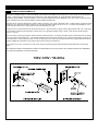
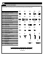
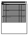
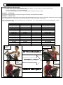
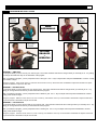
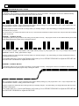
1
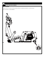
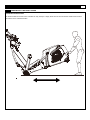
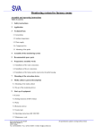
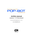
CX8 Elliptical Cross Trainer TABLE OF CONTENTS 1. PRECAUTIONS................................. P2 2. POWER REQUIREMENTS.......................... .. P3 3. BEFORE YOU BEGIN.............................. P4 4. SUPPLIED COMPONENTS / SUPPLIED HARDWARE.............. P5~P6 5. PARTS LIST................................ P7~P11 6. OPEN BOX & ASSEMBLY INSTRUCTIONS. ................ P12~P20 7. EXPLODED DIAGRAM........................... P21~P26 8. STABILIZER ADJUSTMENT.......................... .P27 9. TRANSPORT INSTRUCTIONS.......................... P28 10. IMPORTANT STEPS.............................. P29 12. MUSCLE CHART............................... P30 13. STRETCHING ROUTINE............................ P31 14. COMPUTER OPERATION......................... P32~P37 Serial Number: ________________________ Original Sales Order # ________________________ Purchase Date: ______________ 2 LANDICE CX8 CROSS TRAINER PRECAUTIONS Opening the box: You are now ready to unbox your new equipment. Make sure to inventory all of the parts that are included in the boxes. Check the Parts List for a full count of the number of parts included for this product so it can be assembled properly. If you are missing any parts or have any assembly questions call your local dealer or contact us directly at 1-800-LANDICE. Gather your tools: Before starting the assembly of your unit, make sure that you have gathered all the necessary tools required to assemble the unit properly. Having all of the necessary equipment at hand will save time and make the assembly quick and hassle-free. Clear your work area: Make sure that you have cleared away a large enough space to properly assemble the unit. Make sure the space is free from anything that may cause injury during assembly. After the unit is fully assembled, make sure there is a comfortable amount of free area around the unit for unobstructed operation. It is recommended to leave a minimum of 18” of free space (clearance) around the unit and 36” in the front. Invite a friend: Some of the assembly steps may require heavy lifting. It is recommended that you obtain the assistance of another person when assembling this product. User Weight Limitation: Please note that there is a weight limitation for this product. If you weigh more than 400Lbs. it is not recommended that you use this product. Serious injury may occur if the user’s weight exceeds the limit shown here. This product is not intended to support users whose weight exceeds this limit. 3 POWER REQUIREMENTS IMPROPER CONNECTION OF THE EQUIPMENT GROUNDING CONNECTOR CAN RESULT IN THE RISK OF AN ELECTRIC SHOCK. CHECK WITH A QUALIFIED ELECTRICIAN IF YOU ARE IN DOUBT AS TO WHETHER THE PRODUCT IS PROPERLY GROUNDED. DO NOT MODIFY THE PLUG PROVIDED WITH THE PRODUCT, IF IT WILL NOT FIT THE OUTLET; HAVE A PROPER OUTLET INSTALLED BY A QUALIFIED ELECTRICIAN. This CX8 can be seriously damaged by sudden voltage changes in your home’s electrical power. Voltage spikes, surges and noise interference can result from weather conditions or from other appliances being turned on or off. To reduce the possibility of cross trainer damage, always use a surge protector (not included) with your CX8. Surge protectors can be purchased at most hardware stores. We recommend a single outlet surge protector with a UL 1449 rating as a Transient Voltage Surge Suppressor (TVSS) with a UL suppressed voltage rating of 400V or less and an electrical rating 110VAC, 15 amps. This cross trainer must be grounded to reduce the risk of electrical shock. Grounding provides a path of least resistance for electric current, should the CX8 malfunction. This CX8 is equipped with an electrical cord that has an equipment-grounding conductor and a grounding plug. Always plug the power cord into a surge protector, and plug the surge protector into an appropriate outlet that is properly installed and grounded in accordance with all local codes and ordinances. This product is for use on a nominal 110-volt circuit, and has a grounding plug that looks like the plug illustrated in the drawing below. GFCI outlets and GFCI Circuit Breakers are NOT recommended for use on this product. GFCI outlets and GFCI Circuit Breakers may cause this equipment to function improperly. 100V-125V / 50-60hz 4 LANDICE CX8 CROSS TRAINER BEFORE YOU BEGIN Before assembling or using the CX8, please read the following instructions carefully. They contain important information for use and maintenance of the equipment as well as for your personal safety. Keep these instructions in a safe place for maintenance purposes or for ordering spare parts. Product-Scope: This product is made for home use and LTD (light commercial) only and tested up to a maximum body weight of 400lbs. Product-Performance: This ergo meter is speed independent, i.e. the performance is independent from pedal frequency. Product-Feature: The resistance can be changed by the computer. Use-Scope: The CX8 may not be used by individual over 400lbs. Use-Scope: This product is designed for physical exercise by adults. Please ensure that children only use it under the supervision of an adult. The cross trainer is not recommend for use by children. Use-Environment: Ensure that those present are aware of possible hazards, e.g. movable parts during training. Use-Environment: Ensure that sufficient space is available to use the cross trainer. Use-Environment: Place the cross trainer on an even, non-slippery surface. Use-Environment: Please ensure that liquids or perspiration never enter the machine or electronics. Use-Environment: Keep the equipment indoors, away from moisture and dust. Do not put the equipment in a garage or covered patio, or near water. Use-Environment: The product is made for home or LTD (light commercial) use only. Warranty and manufacturer's liability do not extend to any product or damage to the product caused by commercial purposes. User-Health: Consult your physician before starting any exercise programs to receive proper training advice. User-Health: Incorrect/excessive training can lead to injuries. User-Health: If you feel sick, chest pain, dizzy or loss of breath during your training, immediately stop the training and consult your physician. Product-Preparation: Ensure that training only starts after correct assembly, adjustment and inspection of the cross trainer. Product-Preparation: Follow the steps of the assembly instructions carefully. Product-Preparation: Only use suitable tools for assembly and ask for assistance if necessary. Product-Preparation: Only use original LANDICE parts as delivered (see checklist). Use-Preparation: Tighten all adjustable parts to prevent sudden movement while training. Use-Instruction: Please follow the advice to correct training as detailed in the training instructions. Use-Instruction: Do not use the CX8 without shoes or with loose shoes. Use-Safety: Be aware of non-fixed or moving parts while mounting or dismounting the CX8. Use-Safety: Use the height adjustment caps on the rear tube to ensure stable position of the CX8. Use-Safety: Make sure the front wheels are placed in the correct position: see assembly instructions. Product-Power-Safety: The unit requires a power supply of 100V – 125V / 50-60Hz. It should be connected to a safety socket with a single 10A fuse. After completing electrical connection, confirm that all the connections are secure and using intended male/female connectors. Product-Maintenance: If the equipment is regularly used, check all its components thoroughly every 1 – 2 month. Pay particular attention to the tightness of bolts and nuts. This applies especially to the securing bolts for upright and handlebars. Product-Maintenance: Incorrect repairs and structural modifications (e.g. removal or replacement of original parts) may endanger the safety of the user. Product-Maintenance: Damaged components may endanger your safety or reduce the lifetime of the equipment. For this reason, worn or damaged parts should be replaced immediately and the equipment taken out of use until this has been done. Product-Maintenance: Only use original LANDICE spare parts. Product-Maintenance: Do not under any circumstances carry out electrical repairs or alterations yourself. Always ensure that such work is done by a properly qualified electrician. Product-Maintenance: Disconnect the apparatus from wall socket so there is no power to the unit before doing repair, maintenance or cleaning. 5 SUPPLIED COMPONENTS This list identifies the major components you will use to assemble this product. No. Description Qty. 102 Moving Handlebar-Left 1 103 Moving Handlebar-Right 1 341 2 342 Incline Frame Lower Cover-Rear Incline Frame Lower CoverFront 701 Action Arm Lower Cover 4 702 Pedal Arm Front Pivot Cover 2 703 Incline Frame Front Cover 1 704 Undercarriage Cover - Left 1 705 Undercarriage Cover -Right 1 708 Incline Frame Holder - Front 2 709 Water Bottle Holder 1 H Chest Belt 1 I Power Cord 1 A1 Console PC Board Assembly 1 A2 Console Upright Assembly 1 A3 Incline Frame Assembly 1 A4 Main Frame Assembly 1 2 6 LANDICE CX8 CROSS TRAINER SUPPLIED HARDWARE This list identifies the hardware you will use to assemble the product. To help distinguish between the various types of screws and bolts, use the scale below to measure them and compare them to the sizes listed. No. Description Qty. 408 4x15mm Screw – Cone point 4 461 M6 Nylon Nut 4 501 4x12mm Screw – Cone Point 5 502 15x22 – M6x10mm Bolt 2 503 15x26 – M8x15mm Bolt 2 504 M8x20mm Allen Head CAP Bolt 4 505 20x79.9-M14x25mm Bolt 2 506 4x12mm Screw – Flat Point 4 507 M10x56mm Allen Head Bolt 1 508 M10 Nylon Nut 1 509 4x19mm Screw 4 510 4.5x12mm Screw 4 511 M10x40mm Allen Head CAP Bolt 4 514 M6x20mm Allen Head Bolt 6 516 M5x6mm Screw 2 517 10x16x2mm Spring Washer 4 518 4x13x1mm Washer 1 520 4.5x15mm 2 521 20.7x29.1x0.3mm Wave Washer 2 A 2.5mm Allen Key 1 B 5mm T-Type Allen Key 1 C 8mm Allen Key 1 D 6mm Allen Key 1 E Screwdriver 1 F 13&17 Wrench 1 G 13 &17 Combination Wrench 1 408 461 501 502 503 504 505 506 507 508 509 510 511 514 516 517 518 MILLIMETERS 520 521 7 PART LIST Item No. Description Qty. Part No. CX8-100 101 102 103 104 105 106 107 108 109 110 112 113 115 118 119 120 121 Console Support Tube Moving Handlebar – Left Moving Handlebar – Right Moving Linkage – Left Moving Linkage – Right Pedal Arm – Left Pedal Arm – Right Pedal Swing Arm Incline Frame Incline Transmission TubeMain Frame Incline Switch Sensor Plate Tension Wheel Bracket Action Arm – Left Action Arm – Right Cover Support Tube - Rear Cover Support Tube - Front 1 1 1 1 1 1 1 2 1 1 1 1 1 1 1 1 1 CX8-101 CX8-102 CX8-103 CX8-104 CX8-105 CX8-106 CX8-107 CX8-108 CX8-109 CX8-110 CX8-112 CX8-113 CX8-115 CX8-118 CX8-119 CX8-120 CX8-121 Flywheel Fixed Plate - Left Flywheel Fixed Plate - Right Elector-Magnetic Adjusted Plate Console Cover Support Rear Plate - Left Console Cover Support Rear Plate - Right Incline Frame Holder – Rear Bearing 2201 Moving Linkage Bushing Bearing 2203 Bearing 6205 Bushing 16x22.2x10.7mm Bushing 18x12mm Flywheel Pivot Bearing 6203 Flywheel Bearing 6300 Crank Crank Disk Crank Disk Oval Cap Bearing 6005 Crank Disk Pivot Crank Pivot Bushing Belt Level Adjuster Control Board Base Speed Sensor Base 1 1 1 1 1 2 2 4 2 4 4 2 1 2 1 2 2 1 1 2 1 1 1 2 1 2 CX8-201 CX8-202 CX8-203 CX8-204 CX8-205 CX8-206 CX8-211 CX8-213 CX8-215 CX8-217 CX8-219 CX8-220 CX8-221 CX8-222 CX8-224 CX8-225 CX8-226 CX8-227 CX8-228 CX8-230 CX8-231 CX8-232 CX8-233 CX8-234 CX8-235 CX8-236 CX8-200 201 202 203 204 205 206 211 213 215 217 219 220 221 222 224 225 226 227 228 230 231 232 233 234 235 236 8 LANDICE CX8 CROSS TRAINER PART LIST Item No. Description 238 Overlay 241 Bearing 6904 Qty. Part No. 1 10 CX8-238 2 2 2 1 1 1 1 2 2 2 1 2 2 4 1 1 1 2 2 2 2 2 2 1 1 2 1 1 1 1 2 2 2 2 1 1 1 CX8-301 2 2 44 CX8-401 CX8-241 CX8-300 301 Plastic Bushing 20X26X6mm 302 Plastic Bushing 22X26X6mm 303 Hand Pulse Sensor Cover 304 Button Cover – Top 305 Button Cover – Bottom 306 Console Bottom Cover – Left 307 Console Bottom Cover – Right 311 Pivot Cap 312 Action Arm Drive Gear 313 Moving Handlebar Drive Gear 319 Switch Plate 320 Pedal Soft Cushion 321 Pedal 324 Pedal Buffer Cover 325 Vent Cover – Rear 326 Rear Shroud Inlet – Left 327 Rear Shroud Inlet – Right 328 Lift Handlebar End Cap 329 Pedal Swing Arm Cap 330 Incline Frame Positioner 331 Wheel Cap 112x41.5mm 332 Wheel Cap 46x12mm 333 Wheel 140x51.86mm 334 Bearing Bracket 335 Control Board Cover 336 Oval Tube Cap 337 Vent Cover – Left 338 Rear Shroud – Left 339 Rear Shroud – Right 340 Vent Cover –Right 341 Incline Frame Lower Cover – Rear 342 Incline Frame Lower Cover – Front 343 Incline Frame Top Cover – Rear 344 Incline Frame Top Cover – Front 346 iPod Dock Bracket Cover – Top 347 iPod Dock Bracket Cover – Bottom 351 iPod Cushion CX8-302 CX8-303 CX8-304 CX8-305 CX8-306 CX8-307 CX8-311 CX8-312 CX8-313 CX8-319 CX8-320 CX8-321 CX8-324 CX8-325 CX8-326 CX8-327 CX8-328 CX8-329 CX8-330 CX8-331 CX8-332 CX8-333 CX8-334 CX8-335 CX8-336 CX8-337 CX8-338 CX8-339 CX8-340 CX8-341 CX8-342 CX8-343 CX8-344 CX8-346 CX8-347 CX8-351 CX8-400 401 8x27x2mm Washer 402 3x12mm Screw – Cone Point 403 Taper Fixing Insert CX8-402 CX8-403 9 PART LIST Item No. 404 405 406 407 408 409 410 411 412 413 415 416 417 418 419 421 422 423 424 425 426 427 429 430 431 432 434 435 436 437 438 439 440 441 442 445 446 447 448 449 451 452 453 454 455 456 457 Description M8x16mm Allen Head CAP Bolt 8x14xT2.0mm Spring Washer M10x20mm Allen Head Cap Bolt 4x15mm Screw – Flat Point 4x15mm Screw – Cone Point 3x15mm Screw – Flat Point M8x20mm Screw 4x12mm Screw – Cone Point M32 C Clip 12x20x2mm PU Washer M8x20mm Allen Head Bolt M6 Nylon Nut M8 Nylon Nut 25mm C Clip M3X6X2.4 mm Nut M12 C Clip M10X45X15mm Tension Wheel Bolt 4.5x15mm Screw M6x12mm Allen Head CAP Bolt 6x10x1mm Spring Washer 20x6x1.5mm Washer M42 C Clip M10x20mm Bolt 10x16x2mm Spring Washer 10x30x1 Plastic Washer M4 Nylon Nut 8x27x1mm Plastic Washer 16x25xT3.0 Washer M10x40mm Allen Head Bolt M6x12mm Screw 17x22xT1.5mm Plastic Washer M8x50mm Allen Head CAP Bolt 32x6x2.0 Washer M6X30X30mm Allen Key Bolt M22 Nut Pedal Arm Pivot 3/4” Nut M10X30X30mm Allen Head CAP Bolt M4x15mm Screw 4x12mm Screw M4X40X40mm Allen Head CAP Bolt M5x8mm Allen Head Bolt M4x6mm Screw Pin Nut M4x45mm Screw M3x8mm Screw U - Iron Screw Hole Plate -5*12.5*20mm Qty. 1 7 4 4 4 4 2 50 2 2 2 1 3 2 2 2 1 2 8 35 6 2 2 8 1 2 2 4 1 14 3 2 1 2 2 2 6 2 2 6 1 2 4 4 2 2 8 Part No. CX8-404 CX8-405 CX8-406 CX8-407 CX8-408 CX8-409 CX8-410 CX8-411 CX8-412 CX8-413 CX8-415 CX8-416 CX8-417 CX8-418 CX8-419 CX8-421 CX8-422 CX8-423 CX8-424 CX8-425 CX8-426 CX8-427 CX8-429 CX8-430 CX8-431 CX8-432 CX8-434 CX8-435 CX8-436 CX8-437 CX8-438 CX8-439 CX8-440 CX8-441 CX8-442 CX8-445 CX8-446 CX8-447 CX8-448 CX8-449 CX8-451 CX8-452 CX8-453 CX8-454 CX8-455 CX8-456 CX8-457 10 LANDICE CX8 CROSS TRAINER PART LIST tem No. 458 459 460 461 463 464 465 467 468 469 471 472 473 476 477 478 479 483 486 487 488 489 Description Qty. Part No. M5x12mm Screw M8x45mm Bolt 8x16xT1.0mm Washer M6 Nut M6X15X15 Screw – Flat Point 5/12" X32mm Allen Head Bolt 6x14.5–M5x6.5mm Bolt M5x15mm Screw M5 Nut 5mm Lock Washer M5X45mm Screw 4x15mm Screw 2X10mm Screw – Flat Point M5 Nylon Nut 5X10X1mm Washer 10X19X3mm Washer 10X23X2mm Washer 6X13XT1.5 Washer 5/16" Nylon Nut U - Iron Screw Hole Plate -5*11*16.5mm 8X18X2mm Washer M6X25X25mm Allen Head CAP Bolt 2 3 3 4 2 4 2 9 6 3 3 8 2 4 1 1 1 4 4 6 2 2 CX8-458 CX8-459 CX8-460 CX8-461 CX8-463 CX8-464 CX8-465 CX8-467 CX8-468 CX8-469 CX8-471 CX8-472 CX8-473 CX8-476 CX8-477 CX8-478 CX8-479 CX8-483 CX8-486 CX8-487 CX8-488 CX8-489 4x12mm Screw 15x22–M8x10mm Bolt 15x26–M8x15mm Bolt M8X16mm Allen Head CAP Bolt 20x79.9-M14x25mm Bolt 4x12mm Screw – Flat Point M10x56mm Allen Head Bolt M10 Nylon Nut 4x19mm Screw 4.5x12mm Screw M10x40mm Allen Head CAP Bolt M6x20mm Allen Head CAP Bolt M5x8mm Screw 4X12X1mm Washer 4.5x15mm Screw 20.7x29.1x0.3mm Wave Washer 1 2 2 4 2 7 1 3 4 4 4 6 2 1 2 2 CX8-501 CX8-502 CX8-503 CX8-504 CX8-505 CX8-506 CX8-507 CX8-508 CX8-509 CX8-510 CX8-511 CX8-514 CX8-516 CX8-518 CX8-520 CX8-521 8Pin Power Wire – Upper 8Pin Power Wire – Lower Elector-Magnetic Wire 1 Pin Power Connection Wire 3C Power Wire Hand Pulse Sensor Wire 2 Pin Hand Pulse Sensor Wire – Lower Console PC Board 1 1 1 3 1 2 2 1 CX8-601 CX8-602 CX8-604 CX8-605 CX8-606 CX8-607 CX8-609 CX8-610 CX8-500 501 502 503 504 505 506 507 508 509 510 511 514 516 518 520 521 CX8-600 601 602 604 605 606 607 609 610 11 PART LIST Item No. 612 613 614 615 616 617 618 619 620 621 622 623 624 625 626 627 628 632 633 634 Description Qty. Part No. Receiver Wire Membrane Button Overlay Fan HR Receiver Elevation Motor Speed Sensor Transformer Control Board Power Insert Power Switch Power Breaker Elector-Magnetic System Magnetic Sensor Micro switch 10A Incline 3C Power Connector Wire Right Angle Audio Cable Incline Motor Sensor Connector iPod dock Speaker Amplifier PC board 1 1 1 1 1 1 1 1 1 1 1 1 1 2 1 1 1 1 2 1 CX8-612 CX8-613 CX8-614 CX8-615 CX8-616 CX8-617 CX8-618 CX8-619 CX8-620 CX8-621 CX8-622 CX8-623 CX8-624 CX8-625 CX8-626 CX8-627 CX8-628 CX8-632 CX8-633 CX8-634 Action Arm Lower Cover Pedal Arm Front Pivot Cover Incline Frame Front Cover Undercarriage Cover – Left Undercarriage Cover – Right Nylon Bushing Incline Frame Holder – Front Water Bottle Holder 4x15mm Screw – Flat Point 4 2 1 1 1 1 2 1 8 CX8-701 CX8-702 CX8-703 CX8-704 CX8-705 CX8-706 CX8-708 CX8-709 CX8-742 CX8-700 701 702 703 704 705 706 708 709 742 12 LANDICE CX8 CROSS TRAINER HOW TO OPEN BOX 1. Cut the plastic straps straps. 13 HOW TO OPEN BOX 2. Cut the box along the bottom all the way around and lift the box from pallet. 3. Carefully cut away all plastic wrap and remove all components leaving only frame strapped to pallet. 4. Cut the straps both at the front and back of unit. 14 LANDICE CX8 CROSS TRAINER HOW TO OPEN BOX 5. Set unit on floor and discard pallet. 15 ASSEMBLY 6. Set upright-(A2) on base mount (carefully hold it until you secure it with bolts in next step). 16 LANDICE CX8 CROSS TRAINER ASSEMBLY D 7. Use 6mm Allen key (D) to secure the M8 X 20mm Allen Head cap bolts (#504). 504 X4 17 ASSEMBLY 506 510 506 510 OPPOSITE SIDE 509 8. Complete harness connection from base of upright to frame. 9. With the pedal arm in the high position, carefully slip the middle shroud cover up into position from beneath. 10. Attach the pedal shroud using screws 4 x #506 (2 per side), 4 x #509 (all 4 on one side – see image) , and 4 x #510 (2 per side) 506 X4 509 X4 510 X4 18 LANDICE CX8 CROSS TRAINER ASSEMBLY 520 520 11. Attach front shroud cover using screws 2 x #520 520 X2 19 ASSEMBLY 502 503 12. Connect the action arm moving linkage using a 6mm Allen key(D): bolts #502 and #503 502 X2 503 X2 20 LANDICE CX8 CROSS TRAINER ASSEMBLY 411 E 13. Remove the preinstalled screws #411. Attach the plastic covers and reinstall the #411 screws 411 X4 21 ASSEMBLY 407 407 E 14. Remove the hardware preinstalled in the plastic covers to be used for installation. Install the front/back incline support covers using screws #407. 407 X4 22 LANDICE CX8 CROSS TRAINER ASSEMBLY 15. Once you install one side of the front/back incline support covers, the other snaps into the one you just secured. 23 ASSEMBLY E 16. Install the outside incline support covers using screws #458 which is already preinstalled. 17. Connect power cord to rear with red power switch set to OFF. Connect the line cord to the wall and turn the red power switch to ON. 458 X2 24 LANDICE CX8 CROSS TRAINER EXPLODED DIAGRAM 412 412 214 514 102 214 514 514 103 514 514 514 446 301 446 301 313 313 241 303 302 241 303 442 442 302 464 464 441 486 486 416 486 441 416 464 486 464 245 504 312 245 401 494 405 706 706 494 245 312 434 401 245 501 504 405 434 518 119 709 118 101 501 504 501 701 501 701 701 501 701 504 504 503 421 502 503 502 412 413 211 104 211 504 105 413 412 421 25 EXPLODED DIAGRAM 424 320 321 425 427 215 215 427 426 424 426 320 321 425 324 324 411 461 461 213 241 241 521 505 107 106 461 461 403 403 324 324 411 411 213 213 702 702 411 461 461 213 241 505 521 241 26 LANDICE CX8 CROSS TRAINER EXPLODED DIAGRAM 108 108 418 425 438 221 437 334 438 402 224 217 458 217 425 438 402 311 437 222 437 217 516 426 217 418 425 425 437 201 222 430 425 435 424 437 202 329 219 329 330 508 334 425 507 411 219 331 429 332 333 435 430 435 109 435 333 625 233 419 409 447 445 227 226 432 112 624 411 625 446 113 425 414 425 410 411 437 425 437 439 460 417 410 459 203 488 405 405 228 332 448 404 405 460 417 495 230 220 220 417 623 411 231 425 618 411 495 110 405 232 440 230 237 414 207 447 445 446 226 436 408 431 485 508 493 616 429 331 27 EXPLODED DIAGRAM 509 408 509 703 342 408 520 403 341 506 704 509 506 338 403 477 506 403 403 510 457 457 510 403 326 411 471 341 408 411 457 344 407 407 511 518 343 408 343 708 487 411 518 411 471 403 120 411 225 411 478 422 411 468 617 479 489 425 411 454 708 344 483 451 462 705 206 121 457 518 508 452 115 467 453 335 510 518 411 472 342 403 455 235 469 468 327 406 506 510 457 411 619 483 425 424 457 487 325 337 411 328 411 340 487 423 319 411 411 403 411 411 328 336 472 487 234 456 620 622 621 234 336 339 411 28 LANDICE CX8 CROSS TRAINER EXPLODED DIAGRAM 346 610 238 473 613 632 347 465 614 463 449 449 304 305 463 468 306 468 467 467 416 204 416 466 466 467 467 351 205 468 468 449 633 449 403 307 449 29 WIRE DIAGRAM 614 627 607 632 609 607 633 633 601 609 303 303 610 609 609 615 601 635 601 618 612 606 606 602 628 617 619 602 618 604 617 620 605 606 622 625 621 626 616 628 30 LANDICE CX8 CROSS TRAINER STABILIZER ADJUSTMENT LEVEL ADJUSTMENT: To adjust the level of the CX8 cross trainer simply rotate the Level Adjusters clockwise or counter clockwise. Tilt the cross trainer to access stabilizers. 31 TRANSPORT INSTRUCTIONS TRANSPORT INSTRUCTIONS: The casters located on the rear of the unit allow for easy transport. Simply lift the front of the unit until the wheels touch the floor. Then roll the unit to a desired location. 32 LANDICE CX8 CROSS TRAINER IMPORTANT STEPS Warning: Before using this product, please consult your personal physician for a complete physical examination. Frequent and strenuous exercise should be approved by your doctor first. If any discomfort should result from your use of this product, stop exercising and consult your doctor. Proper usage of this product is essential. Please read your manual carefully before exercising. Please keep all children away from the equipment during use and when equipment is unattended. Always wear appropriate clothing, including athletic shoes, when exercising. Do not wear loose clothing that could become caught during exercising. Make sure that all bolts and nuts are tightened when equipment is in use. Periodic maintenance is required on all exercise equipment to keep it in good condition. Before beginning: How you begin your exercise program depends on your physical condition. If you have been inactive for several years, or are severely overweight, you must start slowly and increase your time gradually, a few minutes per week. Initially you may be able to exercise only for a few minutes in your target zone. However, your aerobic fitness will improve over the next six to eight weeks. Don’t be discouraged if it takes longer. It’s important to work at your own pace. Ultimately, you’ll be able to exercise continuously for 30 minutes. And the better your aerobic fitness, the harder you will have to work to stay in your target zone. But remember these essentials: Contact your physician before starting a workout or training program. Have your doctor review your training and diet programs to advise you of a workout routine you should adopt. Begin your training program slowly with realistic goals that have been set by you and your doctor. Supplement your program with some type of aerobic exercise such as walking, jogging, swimming, dancing and/or bicycling. Monitor your pulse frequently. If you do not have an electronic heart rate monitor, have your physician show you the proper way to manually check your pulse by using your wrist or neck. Establish your target heart rate based on your age and condition. Drink plenty of fluids during the course of your routine. You must replace the water content lost from excessive exercising to avoid dehydration. Avoid drinking large amounts of cold liquids. Fluids should be at room temperature when consumed. 33 MUSCLE CHART Targeted muscle groups: 34 LANDICE CX8 CROSS TRAINER STRETCHING ROUTINE Warm up and cool down: A successful exercise program consists of a warm-up, aerobic exercise, and a cool-down. Do the entire program at least two and preferably three times a week, resting for a day between workouts. After several months, you can increase your workouts to four or five times per week. Warming up is an important part of your workout, and should begin every session. It prepares your body for more strenuous exercise by heating up and stretching out your muscles, increasing your circulation and pulse rate, and delivering more oxygen to your muscles. At the end of your workout, repeat these exercises to reduce sore muscle problems. We suggest the warm-up and cool-down exercises on the following pages: Toe Touch: Slowly bend forward from your waist, letting your back and shoulders relax as you stretch toward your toes. Reach down as far as you can and hold for 15 counts. Shoulder Lift: Lift your right shoulder up toward your ear for one count. Then lift your left shoulder up for one count as you lower your right shoulder. Inner Thigh Stretch: Sit with the soles of your feet together with your knees pointing outward. Pull your feet as close into your groin as possible. Gently push your knees towards the floor. Hold for 15 counts. Hamstring Stretch: Sit with your right leg extended. Rest the sole of your left foot against your right inner thigh. Stretch toward your toe as far as possible. Hold for 15 counts. Relax and then repeat with left leg extended. Side Stretch: Open your arms to the side and continue lifting them until they are over your head. Reach your right arm as far upward toward the ceiling as you can for one count. Feel the stretch up your right side. Repeat this action with your left arm. Calf-Achilles Stretch: Lean against a wall with your left leg in front of the right and your arms forward. Keep your right leg straight and the left foot on the floor; then bend the left leg and lean forward by moving your hips toward the wall. Hold, and then repeat on the other side for 15 counts. Head Roll: Rotate your head to the right for one count, feeling the stretch up the left side of your neck. Next, rotate your head back for one count, stretching your chin to the ceiling and letting your mouth open. Rotate your head to the left for one count, and finally, drop your head to your chest for one count. 35 MANUAL MODE OPERATION DISPLAY FUNCTIONS: Press the START button to start exercise, 1. EFFORT Levels starts from L1 to L16, press EFFORT +/- to adjust the resistance levels. 2. INCLINE Levels starts from L1 to L12, press INCLINE +/- to adjust the motion levels. STOP: Press STOP button to shut off console screen, and press any button of console to power the screen on. EFFORT LEVEL DISPLAY: Displays Effort Level from L1 to L16. INCLINE LEVEL DISPLAY: Displays Motion Level from 1 to 12. The % Grade and Stride Path Length for each Motion Level will be temporarily displayed during each change. FAN: Adjust Fan to 3 different settings: Level 1 Level 2 Level 3 VOLUME: Adjust volume of Audio Player or iPod. PROGRAM / ENTER: Press Program/Enter to view available programs. Use +/- keys to scroll through all programs. To select the program you want – Press PROGRAM/ENTER MANUAL / EXIT: Press Manual/Exit at any time to return to MANUAL MODE at any time. In Manual Mode, you keep all manual control of effort and incline. 8 X 16 DOT MATRIX RESISTANCE LEVEL PROFILE DISPLAY: Displays all operating instructions prior to the workout and displays RESISTANCE level profile during the workout. ENGLISH/METRIC CONVERSION: The elliptical displays ENGLISH and METRIC information. When the display reads “MPH” it’s in ENGLISH mode and display “KM/H” is METRIC mode. You can see your current setting at the left lower corner of screen, ENGLISH or METRIC. In case that the elliptical needs to be converted between METRIC and ENGLISH readout, please follow the procedure as below: 1. 2. 3. 4. POWER SWITCH to ON then Press both INCLINE UP and DOWN buttons at the same time, and hold them for 3 seconds. The display will sound one short beep, and then go into current computer version check. Press PROGRAM and “En 1” will blink on the top left corner. Please presses PROGRAM again which will go into conversion channel, and then you can press INCLINE/ EFFORT UP DOWN to select which mode that you needed. Press PROGRAM button to save this setting, and press EXIT button twice to back power on status. SLEEP MODE: If the unit is left idle for: 10 Seconds: The unit enters PAUSE and inclines returns to Level 1 to facilitate an easier restart. If pedaling resumes, the incline will return to its previous setting and the unit will resume from PAUSE MODE. 5 Minutes: The display will shut down to go in sleep mode to conserve energy. 36 LANDICE CX8 CROSS TRAINER PROGRAM OPERATION INSTRUCTIONS: Press PROGRAM at any time to enter the PROGRAM SELECTION MENU. The first Program to appear is DEMO MODE. To view other programs available use the +/- keys To select the program in view, press PROGRAM Once you select a program, use the +/- to adjust program settings and START to begin. PROGRAM 1 – DEMO MODE This 3 minute program will take you through the range of foot motion and hand positions available. PROGRAM 2 – CARDIO CORE This program will introduce different grip areas combined with pedal directions during your workout. The incline and effort level will not change unless you manually do so. Any setting you change will remain that way for the remainder of the program. When you select this program, you are prompted to enter a program time. Use +/- keys to adjust value and press PROGRAM to continue. Finally, press START to begin. Grip area Upper Grip Bottom Grip Upper Grip Top Grip Lower Grip Stationary handles Bottom Grip Upper Grip Top Grip Lower Grip Right/Upper Grip Left/Upper Grip Bottom Grip Upper Grip Top Grip Lower Grip Upper Grip Movement direction Forward Forward Forward Forward Forward Reverse Forward Reverse Forward Forward Forward Forward Forward Reverse Forward Forward Forward Segment Length 2 1 3 1 3 1 1 3 1 3 1 1 1 3 1 3 1 UPPER GRIP Alpha-Numeric Display UPPER GRIP PUSH UP UPPER GRIP PULL DOWN LOWER GRIP FIXED / REV. PUSH UP UPPER / REV. PULL DOWN LOWER GRIP RIGHT CROSS LEFT CROSS PUSH UP UPPER / REV. PULL DOWN LOWER GRIP DOUBLE CROSS PULL DOWN UPPER OBLIQUES LOWER GRIP INTENSITY/FOCUS PUSH UP LOWER OBLIQUES 37 PROGRAM INSTRUCTIONS RIGHT CROSS LEFT CROSS MAIN ABDOMINALS DOUBLE CROSS FIXED GRIP EXTREME OBLIQUES + SERRATUS PROGRAM 3 – TIME GOAL This program will let you set a Time as your workout goal. The incline and effort level will not change unless you manually do so. Any setting you change will remain that way for the remainder of the program. When you select this program, you are prompted to enter a time goal. Use +/- keys to adjust value and press PROGRAM to continue. Finally, press START to begin. During the program: Time counts down to 0, Distance and Calories count up. Press EFFORT UP/DOWN to adjust the EFFORT and press INCLINE UP/DOWN to adjust the INCLINE. PROGRAM 4 – DISTANCE GOAL This program will let you set a Distance as your workout goal. The incline and effort level will not change unless you manually do so. Any setting you change will remain that way for the remainder of the program. When you select this program, you are prompted to enter a distance goal. Use +/- keys to adjust value and press PROGRAM to continue. Finally, press START to begin. During the program: Distance counts down to 0, Time counts up, and Calories count up. Press EFFORT UP/DOWN to adjust the EFFORT and press INCLINE UP/DOWN to adjust the INCLINE. PROGRAM 5 – CALORIE GOAL This program will let you set a Calorie Total as your workout goal. The incline and effort level will not change unless you manually do so. Any setting you change will remain that way for the remainder of the program. When you select this program, you are prompted to enter a calorie goal. Use +/- keys to adjust value and press PROGRAM to continue. Finally, press START to begin. During the program: Calories counts down to 0, Time counts up, and Distance counts up. Press EFFORT UP/DOWN to adjust the EFFORT and press INCLINE UP/DOWN to adjust the INCLINE. 38 LANDICE CX8 CROSS TRAINER PROGRAM INSTRUCTIONS PROGRAM 6 – FAT BURN This program’s goal is to elevate your heart rate and maintain it for most of your workout. This program can be run at 8 different difficulty levels which can be adjusted during the program setup or during the workout. When you select this program, you are prompted to enter weight, difficulty setting (1-8), and program time. Use +/- keys to adjust value and press PROGRAM to continue. Finally, press START to begin. During the program, the incline level will not change unless you manually change it. Any incline setting you change will remain that way for the remainder of the program. Time counts down to 0, Calories and Distance will count up. Press EFFORT UP/DOWN to adjust the EFFORT and press INCLINE UP/DOWN to adjust the INCLINE. PROGRAM 7 – INTERVAL EFFORT This program’s goal is to vary your Effort Level, taking you from peak to recovery. This program can be run at 8 different difficulty levels which can be adjusted during the program setup or during the workout. When you select this program, are prompted to enter weight, difficulty setting (1-8), and program time. Use +/- keys to adjust value and press PROGRAM to continue. Finally, press START to begin. During the program, the incline level will not change unless you manually change it. Any incline setting you change will remain that way for the remainder of the program. Time counts down to 0, Calories and Distance will count up. Press EFFORT UP/DOWN to adjust the EFFORT and press INCLINE UP/DOWN to adjust the INCLINE. PROGRAM 8 – INTERVAL MOTION This program’s goal is to vary your Incline Level, taking you from peak to recovery. This program can be run at 8 different difficulty levels which can be adjusted during the program setup or during the workout. When you select this program, you are prompted to enter weight, difficulty setting (1-8), and program time. Use +/- keys to adjust value and press PROGRAM to continue. Finally, press START to begin. During the program, the effort level will not change unless you manually change it. Any effort setting you change will remain that way for the remainder of the program. Time counts down to 0, Calories and Distance will count up. Press EFFORT UP/DOWN to adjust the EFFORT and press INCLINE UP/DOWN to adjust the INCLINE. 39 PROGRAM INSTRUCTIONS PROGRAM 9 – ENDURANCE This program’s goal is to vary your Effort and Incline Level, taking you from peak to recovery. This program can be run at 8 different difficulty levels which can be adjusted during the program setup or during the workout. When you select this program, you are prompted to enter weight, difficulty setting (1-8), and program time. Use +/- keys to adjust value and press PROGRAM to continue. Finally, press START to begin. Time counts down to 0, Calories and Distance will count up. Press EFFORT UP/DOWN to adjust the EFFORT and press INCLINE UP/DOWN to adjust the INCLINE. PROGRAM 10 – WATTS CONTROL The function of Watts Control program is to allow the user to set a desired workout load (watts). The user’s workout load is controlled automatically by increasing or decreasing the EFFORT as the user changes their stride cadence (RPM). The EFFORT will be reduced when user increases RPM and the EFFORT will be increased when the user decreases the RPM. When you select this program, you are prompted to enter weight, target WATTS and program time. Use +/- keys to adjust value and press PROGRAM to continue. Finally, press START to begin. During the program, the incline level will not change unless you manually change it. Time counts down to 0, Calories and Distance will count up. Press EFFORT UP/DOWN to adjust the EFFORT and press INCLINE UP/DOWN to adjust the INCLINE. PROGRAM 11 – TARGET HEART RATE CONTROL PROGRAM The TARGET HEART RATE CONTROL program is designed to keep the user training at their chosen heart rate level to achieve the proper workout result. A heart rate monitoring device must be used for this program: Contact Heart Rate Grips or Chest Belt Pulse Transmitter. The equipment provides a standard contact handgrip on the moving handle bar to sense the user’s heart beat during the workout. The user must hold the contact handgrips on the moving handle bar constantly in order to monitor the user heart rate during the workout. A wireless chest belt transmitter is highly recommended for this program since it provides the best most consistent feedback. When you select this program you will be asked for weight, and age. Your age will recommend a recommended Heart Rate. You can change it to a different value at your discretion. IMPORTANT: By default, console software will recommend the user’s recommended SAFE MAXIMUM HEART RATE based on the formula: ((220pbm-AGE) X 75%). User’s are encouraged to consult with a doctor or training consultant to more accurately estimate their SAFE MAXIMUM HEART RATE in order to workout safely. Finally, TIME display shows factory default setting “16:00”. Press EFFORT UP/DOWN button to adjust the target time and press PROGRAM/ENTER to confirm. Press Start to Begin. Once the user successfully enters the HEART RATE CONTROL program, the computer will actively adjust the INCLINE level and EFFORT level to keep the users at the TARGET HEART RATE throughout the program – excluding first 3 minutes and last minute (warm up and cool down). 40 LANDICE CX8 CROSS TRAINER PROGRAM INSTRUCTIONS PROGRAM C1-C5 Custom Program There are 5 Custom Programs. Programs can be up to 1-60 minutes long and can have up to 60 Incline and 60 Effort changes. When you select a custom program, after you enter your weight you can either Press Start to Begin or Program to Edit the program. EDIT MODE: When you select edit, your cursor defaults to the first segment (noted by flashing box) in the LCD dot matrix. Every segment is 1 minute long. Your incline and effort windows show the set incline and effort values for the segment that your cursor is on. Use the effort/incline +/- keys to adjust that segments values to your liking. To make more segments: Press PROGRAM/ENTER To delete a segment: Hold PROGRAM/ENTER (NOTE: when you Delete a segment, you not only delete the segment that you are on but also any segments that follow) To save your changes and start your program: Press START USING THE CHEST BELT HEART RATE MONITOR: For proper operation, the chest belt should be worn with the monitor strapped across the front of your body just above the chest line as shown in the drawing on the right. The monitor needs a little body heat and moisture in order to work properly. To ensure correct operation you may want to wet the two rubber pickups under the belt prior to exercising.