1
User's guide
Version 3.18
June 2013
Copyright 2006, 2013
RND Technology Consultants
Delft
The Netherlands
www.renque.com
-1-
Renque user's guide
Welcome to Renque
Renque is a powerful software environment designed for general-purpose discrete
event simulations. It has a comprehensive graphical user interface and a versatile
simulation engine, which enable you to rapidly build accurate simulations, for a wide
range of applications.
The phrase simulation generally refers to a technique of imitating the behavior of
some process or system by means of operating a project. Simulations are used to
acquire numerical information and improve understanding of systems, in an
environment where experimentation with the real system is undesirable or
impossible.
Renque is a software tool developed to create and operate discrete event simulation
models. A discrete event is something that happens in an instant of time, with zero
duration. Although gradual system transitions can be represented in a Renque
project, the program was designed primarily to deal with instantaneous changes.
Renque is a full-fledged Microsoft Windows application, suitable to analyze a virtually
unlimited range of simulation objectives. Among the many helpful features that make
modeling with Renque efficient and enjoyable are powerful animation tools, Microsoft
Excel embedding, extensive charting possibilities, integrated calendar and
scheduling tools, a helpful event viewer and Microsoft Visual Basic scripting.
In this document, the names of user interface controls are displayed in bold, where
suitable. The names on Renque object properties are written with a capital letter, and
property values are generally displayed in italic. Internal document hyperlinks are
underlined.
Licensing and support
Renque is commercial software. A trial version, which can be used free of charge for
a 14 day period, is available for download on the Renque website
www.renque.com. Please visit the website for information about purchase and
support options.
System requirements
Operating system: Microsoft Windows XP or higher. Integration of Microsoft
Excel is supported for version 97 and later.
-2-
Renque user's guide
1 Contents
1
2
3
4
5
6
Contents............................................................................................................. 3
Getting started.................................................................................................... 5
2.1
Quick start guide ........................................................................................ 6
2.2
Tutorial 1 .................................................................................................. 10
2.3
Tutorial 2 .................................................................................................. 21
Model construction ........................................................................................... 29
3.1
Operation basics ...................................................................................... 30
3.2
Worksheet area ........................................................................................ 31
3.3
Toolbox .................................................................................................... 36
3.4
Menu bar & Toolbar.................................................................................. 37
3.5
Status bar................................................................................................. 42
Object properties .............................................................................................. 43
4.1
General operation .................................................................................... 44
4.2
Component management ......................................................................... 48
4.3
Server properties...................................................................................... 49
4.3.1 General server properties ...................................................................... 49
4.3.2 Operative server properties ................................................................... 50
4.3.3 Resource properties .............................................................................. 52
4.3.4 Fusion properties .................................................................................. 54
4.3.5 Display properties ................................................................................. 55
4.4
Link properties.......................................................................................... 57
4.4.1 Operative link properties ....................................................................... 57
4.4.2 Display properties ................................................................................. 60
4.5
Graph properties ...................................................................................... 62
4.5.1 General graph properties ...................................................................... 62
4.5.2 Content ................................................................................................. 65
4.5.3 Series properties ................................................................................... 66
4.5.4 Makeup ................................................................................................. 69
4.5.5 Axes ...................................................................................................... 70
4.5.6 Legend .................................................................................................. 72
4.5.7 Titles ..................................................................................................... 73
4.5.8 Graph server layout ............................................................................... 73
4.6
Component properties .............................................................................. 75
4.6.1 Variable properties ................................................................................ 75
4.6.2 Attribute properties ................................................................................ 76
4.6.3 Distribution properties ........................................................................... 77
4.6.4 Schedule properties .............................................................................. 79
4.6.5 Picture properties .................................................................................. 84
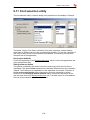
4.7
Incident scripting ...................................................................................... 85
4.8
Annotation ................................................................................................ 88
4.9
Simulation data ........................................................................................ 89
Simulation clock ............................................................................................... 98
5.1
Simulation timing ...................................................................................... 99
5.2
Clock properties ..................................................................................... 100
5.3
Calendar properties ................................................................................ 103
5.4
Timing unit suffix .................................................................................... 105
5.5
Time display ........................................................................................... 106
Simulation operation ...................................................................................... 107
6.1
Running simulations ............................................................................... 108
6.2
Simulation data recording ....................................................................... 110
6.3
Animation ............................................................................................... 113
-3-
Renque user's guide
7
Scripting 115
7.1
Renque syntax rules............................................................................... 116
7.2
Script editing .......................................................................................... 120
7.3
Runtime errors ....................................................................................... 122
7.4
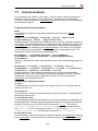
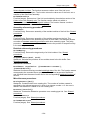
Global procedures .................................................................................. 123
7.5
Entity procedures ................................................................................... 125
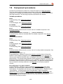
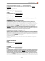
7.6
Server procedures .................................................................................. 127
7.7
Link procedures...................................................................................... 133
7.8
Component procedures .......................................................................... 135
7.9
Clock procedures ................................................................................... 139
7.10 Shared procedures ................................................................................. 142
8 Working with spreadsheets ............................................................................ 146
8.1
Property associations ............................................................................. 147
8.2
Data report ............................................................................................. 149
8.3
Data associations ................................................................................... 150
8.4
Scripting references ............................................................................... 151
8.5
Spreadsheet interaction ......................................................................... 152
8.6
Spreadsheet import ................................................................................ 153
9 Tools & utilities ............................................................................................... 157
9.1
Statistical analysis .................................................................................. 158
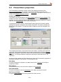
9.2
Presentation properties .......................................................................... 161
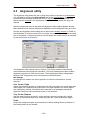
9.3
Alignment utility ...................................................................................... 162
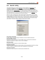
9.4
Search utility .......................................................................................... 164
9.5
Runtime error viewer .............................................................................. 165
9.6
Event viewer .......................................................................................... 166
9.7
Window arrangement utility .................................................................... 168
9.8
Data association manager ...................................................................... 169
9.9
Preferences ............................................................................................ 171
9.10 Paste special utility ................................................................................. 176
9.11 Font selection utility ................................................................................ 178
10 Reference ...................................................................................................... 180
10.1 The Renque simulation engine ............................................................... 181
10.1.1 Simulation mechanism ........................................................................ 181
10.1.2 Operation mechanism of active servers............................................... 183
10.1.3 Operation mechanism of passive servers ............................................ 189
10.1.4 Operation mechanism of resource servers .......................................... 189
10.1.5 Incitation.............................................................................................. 190
10.1.6 Server status ....................................................................................... 191
10.1.7 Property evaluation ............................................................................. 191
10.1.8 Entity displacement ............................................................................. 192
10.1.9 Interruption .......................................................................................... 193
10.1.10 Retraction ......................................................................................... 194
10.1.11 Calendar events ............................................................................... 194
10.2 Random number generation ................................................................... 197
10.3 Formatting by placeholder strings........................................................... 198
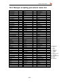
10.4 Renque scripting procedure name list .................................................... 203
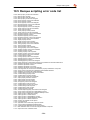
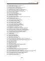
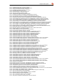
10.5 Renque scripting error code list .............................................................. 204
-4-
Renque user's guide
2 Getting started
This section is intended to familiarize new users with the Renque simulation
environment. It contains an introduction to the user interface and two tutorials:
Quick start guide
Tutorial 1
Tutorial 2
Introduces the Renque user interface and the principles of
simulation modeling in Renque.
Demonstrates the construction and operation of a simple
project for a small supermarket.
Demonstrates the construction and operation of a project for
an industrial production process.
-5-
Renque user's guide
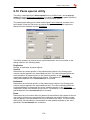
2.1 Quick start guide
This topic contains an elementary tutorial that introduces the main features of
Renque. You will visit and operate the most important elements of the user interface
as you are guided through the construction of a very simple project.
When Renque is started it briefly displays an identifier splash window followed by the
appearance of the primary user interface, recognized by the project name in the title
bar of the window. Models are constructed and simulation runs are viewed on the
Worksheet, which is the large blank area on this window. All other modeling tools and
simulation controls are either located on the Main window as well, or accessible from
it.
A Renque simulation has the three key elements: servers, links and entities.
Server objects act mainly as container and processor of entities. They are
represented by static pictures in the Worksheet. Servers are created during the
construction phase of the project.
Links function as means to transport entities between servers and to create and
destruct entities. Links are displayed on the Worksheet by curves.
Entities are dynamic items in the project. As for servers, they are displayed as
pictures on the Worksheet. However, entities are created and destructed during
the simulation process, and they move around the project.
All project elements may or may not represent physical things found in the real world.
If so, servers typically represent stationary objects such as machinery or storage
facilities, whereas links are better suited to symbolize routes and roads. Entities are
more likely to represent mobile or temporary objects such as materials or documents.
The available server templates are found in the Toolbox on the Main window, located
on the left side of the Worksheet. To add a server to the project, simply use the
mouse to drag the template from the Toolbox and drop it on the Worksheet. Links are
created directly in the Worksheet by connecting two servers with the mouse.
You can create a working project in the following three steps:
1. Create a server on the Worksheet by dragging the Active Template from the
Toolbox and dropping it on the Worksheet.
2. Select the server by clicking on it, somewhere on the left-hand side.
-6-
Renque user's guide
3. Click on the selected Active server with the right mouse button to display a
shortcut menu. Subsequently, click the menu command Add creating link to
connect a link that creates entities to the server.
And there you are: You've created a Renque simulation project. Now, you can run a
simulation by clicking the Restart button on the Toolbar at the top of the window.
When the simulation is running, the animation speed can be altered by the
Animation speed slider control on the Toolbar. The moving circle-shaped icons
represent entities, traveling to the server after having been created on the link. Notice
the simulation time advancing in the right-most pane of the three panes of the Status
bar at the bottom of the window.
-7-
Renque user's guide
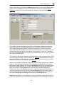
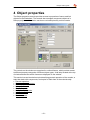
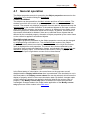
Stop the simulation by clicking the Pause button adjacent to the restart button. Now
double-click the Active server on the Worksheet. A new window named Object
properties is opened. This window serves as console to view and modify object
properties.
The middle of the three boxes at the bottom of the window indicates the selected
state of the server in the Worksheet by the color of the icon. Notice the value 1 for
the Timing property of the server. This value is the cause of the time increment
observed during the simulation. The server forces the creation of an entity on the link,
collects the entity from the link, and retains it for a period of 1 time unit. Thereafter,
the entity is deleted because the server has no downstream links, so there is nothing
else it can do with the entity.
The function of the object properties console depends on the selected tab item at the
top of the window. Similar to the Server tab, the Link tab has a framed set of control
items for properties of selected links. Simulation results, including various recorded
statistics for the server, are viewed on the Data tab.
Next you are invited to extend the project with another server type from the Toolbox:
Passive. Close the Object properties console by pressing Cancel to return to the
Main window. Add a passive server to the Worksheet somewhere to the right of the
previously created active server. Create a link between the two servers as follows:
Move the mouse over the Active server until the mouse pointer changes to a
different icon. Click on the Active server once, and a line appears that will follow the
motion of the mouse. Move the mouse over the Passive server and verify that the
mouse pointer changes once again. Now, click on the Passive server to create a
new link. A straight line connecting the two servers will indicate the link.
Restart the simulation. In the animation you can see that the entities travel from the
Active to the Passive server. On arrival at the Passive server the entities are stored
-8-
Renque user's guide
in the server object. They are shown on a horizontal line, on the left side of the server
picture. The number of stored entities that are displayed is limited by how many fit on
this residents curve. The counter above the server picture indicates the actual
number of entities stored.
Subsequently, pause the simulation and double-click the Passive server to display
the Object properties console again. Notice that the property fields for Timing and
Capacity are blank. These settings make sure that the server stores and retains
every entity it receives.
The active and passive server classes are central in the Renque simulation engine.
Active servers collect entities upstream via one or more connected links. The
collected entities are stored in the server for a specified delay time. After that, the
entities are dispatched to other servers along the links connected at the downstream
side. Active servers repeat this sequence of actions in cycles. In contrast, passive
servers do not collect nor dispatch entities. They simply store arriving entities to await
collection by a downstream active server. A detailed description of the simulation
mechanism is available in the Simulation engine reference section.
The other two server templates in the worksheet, Resource and Graph, have other
functions in a simulation model. Resource servers provide shared resources to active
servers. Graph servers are used to illustrate a model with graphics, text or data
charts.
Renque also has a number of object types that are not displayed on the Worksheet.
These objects are referred to as components, and can be applied to expand the
capabilities of a project in various ways: Attribute and variable components are used
to store data, distribution components provide random variation to a project, and
schedule components perform actions at specified time points in a simulation.
The flow of entities through the project's server and link objects is controlled by a
range of object properties, such as the previously mentioned Timing and Capacity
properties. Although close approximation of a Renque project to the actual system is
generally attainable with the available set of adaptable object properties, exact
matching can not always be accomplished in the diverse intricacy of real systems.
For this reason, a simulation project may be refined by the application of scripting.
Scripts are short user-defined commands, invoked by specific incidents in a
simulation. As all simulation procedures and object properties are accessible by
scripting, the scripting feature provides the designer with an all-purpose tool to
precisely impose the desired project behavior.
This document contains two more tutorials, which are intended to familiarize the user
with the most important user interface items. These tutorials also demonstrate the
application of scripting and components, and introduce some commonly applied
simulation modeling methods.
-9-
Renque user's guide
2.2 Tutorial 1
This tutorial comprises construction and operation of a simple project for a small
supermarket. The level of detail applied to the description of the required user actions
presumes that the reader is familiar with the content of the Quick start guide section
of this document. The tutorial demonstrates server and link properties control, and
interpretation of simulation results within a practical context. Also, it introduces the
application of components to add randomness to the project and to store data in
entities. In addition, it will explain how to use the charting feature and apply scripts to
refine the project.
Imagine a supermarket where costumers arrive, spend some time shopping, choose
a pay desk, wait their turn, and then check out and leave. Suppose the manager of
the supermarket would like to know more about how the waiting time of the
costumers for the check-out routine depends on the number of pay desk operators
put into action. This tutorial demonstrates how to go about in building a Renque
project for the supermarket and extract this kind of information from it.
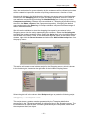
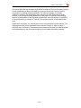
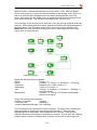
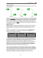
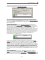
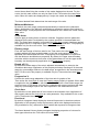
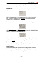
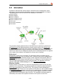
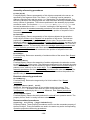
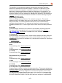
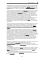
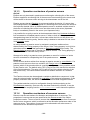
Start the Renque application and create the project displayed in the figure, consisting
of three active and a passive server object and five links. The server names are
assigned by double-clicking a server and typing the desired text into the Name
property text field of the Object properties console.
In this project the server named CostumerEntry is active and has a creating link. The
server will repetitively force the creation of an entity on the link, store it for a specified
period of time and then release it. As a result, it produces a flow of entities, with a
release interval time determined by the Timing property of the server. In the project,
these entities represent the customers arriving at the supermarket. The customer
entities released by the CostumerEntry server are sent to the Shopping server where
they are also stored for a specified time. This delay represents the time spent
shopping by the customers. Upon release by the Shopping server the entities are
sent to the passive Queue server, where they will be stored until the Paydesk server
removes them. The Paydesk server is employed to project the check-out process by
application of another delay. Finally the entities are sent to the destructing link, where
they are removed from the project, representing the departure of the customers from
the shop.
- 10 -
Renque user's guide
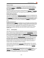
The next step of this tutorial involves manipulation of server properties to obtain the
desired behavior of the project. Double-click the Shopping server to open the Object
properties console and assign the Void value to the Capacity property on the
General tab by clearing the associated text field.
The Void Capacity value results into removal of the Capacity limit from the server.
The Shopping server can now process an unlimited number of customers
simultaneously.
Now select the CustomerEntry and Paydesk servers, and double-click one of them.
Click the Operative tab in the Object properties console to access some more
advanced server properties. Check the Integrated dispatch check box that appears
on this tab.
The Integrated dispatch option prevents a server from collecting new entities until the
entities stored in the server have been dispatched. For the Paydesk server, this
option makes sure that customer entities stay in the Queue server until the checkout
process is complete. Without the option, the next customer entity is already
transferred to the link buffer while the checkout process is still in progress for the
previous customer.
Next, we focus on the CustomerEntry server. As discussed above, the server will
release single customer entities with an interval time equal to the Timing property of
the server, which has a value 1 by default. In reality, the customer interarrival times
at the supermarket will not be uniform, however. Statistics theory dictates that the
interarrival times of such processes are best described by an exponential probability
density function.
- 11 -
Renque user's guide
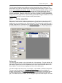
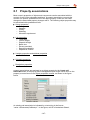
Renque provides functionality for distributed random variation of properties by means
of distribution components. In order to attain the desired exponentially distributed
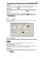
delay of entities in the CustomerEntry server, do the following: Double-click the
CustomerEntry server to open the Object properties console by. In the
Components frame, which is located on the left-hand side of the Object properties
console, right-click the Component repository and select the
New component/Distribution item from the pop-up menu.
This action creates a new distribution component, which appears as selected item in
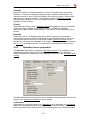
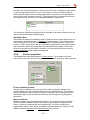
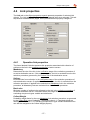
the Component repository. Select the Component tab at the top right of the window
to view the properties of the new distribution component. Change the Probability
density function of the component by selecting the Exponential item in the combo
box, and pressing the Enter key. Keep the default value 1 for the Mean property.
- 12 -
Renque user's guide
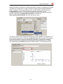
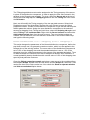
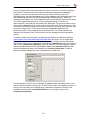
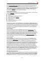
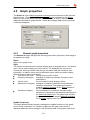
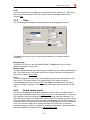
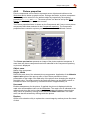
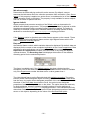
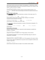
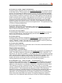
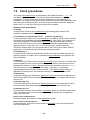
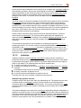
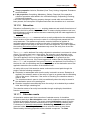
As shown above, the Distribution properties frame contains a plot of the probability
density as function of the random variable. In the supermarket scenario the random
variable is the customer interarrival time. The frequency of occurrence of a specific
interarrival time value is proportional to the probability density. The curve exhibits that
simultaneous arrival of two customers (random variable = 0) is the most likely event
to occur, because it has the highest probability density. Furthermore, the probability
of occurrence decreases rapidly with growing interarrival time.
Return to the Server tab and assign the distribution component to the Timing
property of the selected server by dragging the component item from the repository
and dropping it onto the Timing text field, or by typing the component name in the
text field. Press the OK button.
You have created a new distribution component, named Exponential, of type
Exponential with parameter mean = 1 and assigned it to the Timing property of the
CustomerEntry server. As a result, each time an entity is collected from the creating
link and stored in the server, its’ residence time is set to a value generated by the
Exponential component. The component produces random numbers distributed in
accordance with the mean property, using a built-in random number generator.
Next, following the same procedure, create a distribution component of type
Triangular with properties (min, mod, max) = (1, 5, 20) and assign it to the Timing
property of the Shopping server. This modification makes the Timing property of the
Shopping server random, in accordance with a triangular probability density
distribution with a minimum, modal and maximum value of respectively 1, 5 and 20
time units.
The Paydesk server represents the check-out procedure. Double-click the Paydesk
server and type a value 0.9 in the Timing property text field. In reality the checkout
time will also show random variation and there will be some correlation with the
shopping time. However, for now a uniform checkout time is applied. The value 0.9
renders the customer processing capacity 10% higher than the average customer
arrival rate, imposed by the Exponential distribution component. Press the OK
button.
- 13 -
Renque user's guide
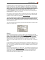
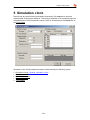
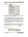
Before running the project the simulation runtime is set. We assume that the time unit
for the project is minutes. Select the Clock command from the Tools menu. Select
the Maximum run time option in the Clock properties console and enter the value
1200 (5 days) in the associated text field. For the present project it in not necessary
to select the Minutes value for the Time unit property. Press the OK button.
The simulation project for the supermarket, although still quite rudimental, is now
ready to be run. Turn the animation mode on and press the Restart button. Watch
the Shopping server initially filling up to some 10 customers, after which the first
customers start arriving in the empty Queue to check out at the pay desk and leave.
After running the project for a while the number of costumers shopping and queuing
vary continuously. At first glance, the simulation project appears realistic.
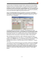
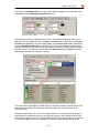
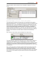
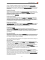
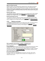
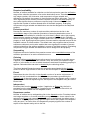
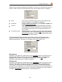
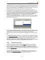
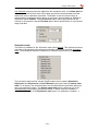
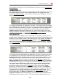
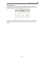
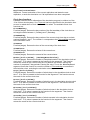
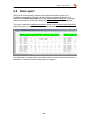
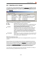
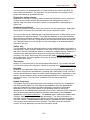
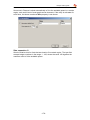
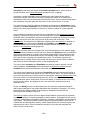
Turn the animation mode off and let the simulation continue until it stops. Doubleclick the Queue server, select the Data tab, and check the Statistics option. The
Object properties console now displays a grid-like sheet, which displays a set of
recorded statistics for the Queue server.
- 14 -
Renque user's guide
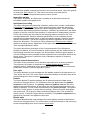
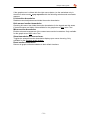
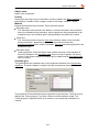
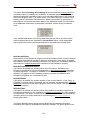
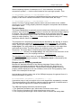
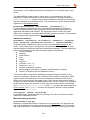
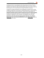
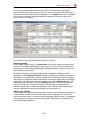
In the top row of the data sheet, the column labeled Maximum reports a maximum
residence time of 20.7 minutes. The reported Mean is 5.7 minutes. Uncheck the
Statistics checkbox and observe that the queue is empty for less that 20% of the
time, as indicated by Idle/Empty field of the Status summary sub-frame.
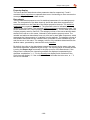
Obviously, the queuing times observed will be unacceptable to the clients of the
supermarket. The excessive maximum results from the interarrival time distribution
applied. The component creates busy next to quiet periods in the supermarket. As
the pay desk capacity is fixed, customers queue up during the busy periods.
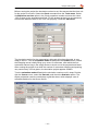
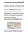
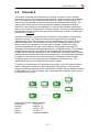
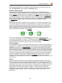
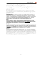
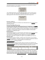
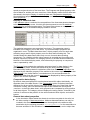
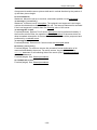
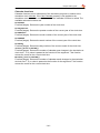
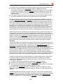
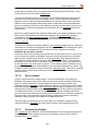
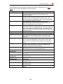
The next step of the tutorial demonstrates how to increase the number of pay desks
in order to reduce customer queuing time. The simplest way to increasing the pay
desk server processing capacity is to increase the Capacity property value. However
this method is unsuitable because each pay desk has its own queue. Instead, select
all server and link objects to the right of the shopping server. Move the mouse pointer
onto the Paydesk server. Now, while keeping the Ctrl key on the keyboard pressed,
drag the server downwards with the left mouse button to duplicate the selected
objects. After a simulation reset the result should look similar to the project displayed
in the figure below.
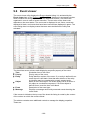
Restart the simulation and let it run until it stops. As expected, the waiting periods
have been reduced significantly. You may verify that a mean value of some 0.14
minutes, or 8 seconds, and a maximum of some 2 minutes are reported for both
queue servers. The improvement is obtained at the expense of the pay desk
occupation, which has become about 46% on average for both pay desk servers.
The latter may be verified by selecting and double-clicking each of the two pay desk
servers, selecting the Data tab and inspecting the values reported in the Occupied
field of the Status summary frame.
The next section of this tutorial enhances the project with shopping time dependent,
random pay desk timing, using an attribute component and some incident scripts.
- 15 -
Renque user's guide
Also, the mechanism for queue selection by the customers will be refined and a chart
will be created to inspect the number of queuing customers as a function of time.
Unselect all objects in the Worksheet by clicking in an empty area on the Worksheet.
Double-click the Shopping server to open the Object properties console. Create a
new attribute component by selecting the New/Attribute item in the pop-up menu
Component repository. Rename the new attribute to TShopping by double-clicking
the cell in the Name column of the Component repository, overtyping the default
name and pressing the Enter key. A Renque attribute component allows storage of
data in individual entities.
We will use the attribute to store the shopping time spent by a customer in the
Shopping server into the entity representing the customer. Select the Scripting tab
to display the Incident scripting frame. Select the Arrive item in the Incidents table on
the left side of the frame. Then, in the Worksheet objects frame, at the bottom of the
window, right-click the Server browser and select the Add incident script item from
the pop-up menu.
This action will create a new incident script for the Shopping server, which is shown
in the Incident grid, located at the right side of the Incident scripting frame.
Select the grid cell in the column titled Script and type or paste the following script:
TShopping = Triangular.eval
This script stores a random number generated by the Triangular distribution
component in the TShopping attribute of entities arriving in the Shopping server. The
Eval statement is used to store a number generated by the component, rather than
the component itself, as object.
- 16 -
Renque user's guide
The TShopping attribute must now be assigned to the Timing property of the server,
in place of the distribution component, in order to apply the time value stored in the
attribute to the Shopping server delay. To do so, select the Server tab at the top of
the window and drag-drop the TShopping attribute into the Timing text field. Press
the OK button.
Next, we will modify the Timing property of the two pay desk servers. Select both
Paydesk servers in the Worksheet. Double-click one of them to open the Object
properties console. Create a new distribution component of type normal and keep the
default parameter values. Assign the new distribution component to the selected
servers by dragging it into Timing text field. Now, select the Scripting tab again and
select Timing in the Incidents table. Right-click the Server browser and select the
Add incident scripts item from the pop-up menu. Two new incident scripts are
created, one for the each of the two servers. Select both in the column titled script’
and type the following script:
Normal.ParametersSet 0.15 * TShopping,(0.015 * TShopping)^2
This script changes the parameters of the Normal distribution component, before the
pay desk servers use it to generate a random number, which is to be applied to the
storage time of the arriving entities. The mean value of the distribution component is
set to 15% of the shopping time and the standard deviation is set to 1.5% of the
shopping time (the variance parameter is the square of the standard deviation). Thus
for each customer the checkout time will be assigned a random value, based on a
normal probability density distribution with a mean value of 15% of the shopping time
spent by that particular costumer.
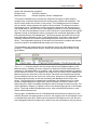
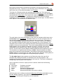
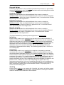
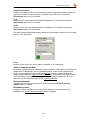
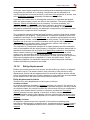
Close the Object properties console and place a new server to the worksheet from
the template Graph. Double-click the new server and the Graph tab, select the Time
series line chart in the Style combo box. Also check the Show in separate window
and Hide on worksheet option boxes.
- 17 -
Renque user's guide
Then select the Makeup tab on the top of the Graph tab page, and select the value
Transparent for the Background pattern fill style.
Subsequently, select the Series tab on the top of the Graph tab page. Add a new
data series to the graph server by dragging the Queue server item from the Server
browser and dropping it into the empty space of the Series grid. Select Population
from the Quantity combo box. In the grid cell of the column labeled Series object,
change the series name from Queue.population.current to Paydesk queue by typing
the new name in the grid cell. Add an identical data series for the Queue 1 server,
and change the name to Paydesk 1 queue.
The Graph server will display a data chart in a separate window, named Graph. The
chart plots the number of customers waiting for their turn in each queue, as a
function of time.
Restart the simulation, let it run until it stops and have a look at the chart. Observe
the number of customers waiting in the queues varying in time. Notice that the two
curves do not match very well. Considerable differences in the number of customers
in the queues appear to occur frequently. In the real supermarket we expect the
- 18 -
Renque user's guide
customers to join the shortest queue after being finished with shopping. Therefore
the queues should typically have about the same length.
The cause for the contrasting behavior lies in the dispatch method of the Shopping
server. The routing of entities from an active server is governed by the Dispatch Rule
applied to the server. Because the Shopping server has the Cycle Dispatch rule, it
sends released entities alternatingly to either queue, whereas dispatch to the link that
connects to the queue server with the least number of residents is desired.
The dispatch routine can be refined by incident scripting. Double-click the Shopping
server to open the Object properties console. Select the Scripting tab and create a
new incident script of type Select dispatch. Assign the following script (by copypaste, if you prefer):
if Queue.Population < Queue 1.Population then
Shopping.RuleLinks.SelectMember(1) else if Queue.Population >
Queue 1.Population then Shopping.RuleLinks.SelectMember(2)
This script forces selection of the link that connects to the queue server with the least
number of residents. The Population function of a server object, used in the script,
returns the number of residents. The RuleLinks.SelectMember procedure
selects a link for the dispatch routine of an entity, overriding the link selection
procedure governed by the Dispatch Rule property of the server. The arguments 1
and 2 denote the link connection number. An alternative and more compact script
line could be applied here, using more advanced scripting procedures, but basic
scripting statements are preferred for this first tutorial.
The script is ineffective if both queues have an equal number of residents. In that
case the entity dispatch routine is determined by the Dispatch Rule. Click the Server
tab at the top of the window, and subsequently the Operative tab. Select the
Random value for the Dispatch Rule property in order to force the destination link of
the entities released from the Shopping server to be selected randomly.
Restart the simulation, let it run until it stops and look at the chart again. You can see
that the curves are almost coinciding. The reported mean and maximum residence
times on the data sheet are well below a minute for the mean and under 5 minutes
for the maximum. The data reported for the Paydesk servers indicate that the
average pay desk occupation is limited to approximately 69%.
- 19 -
Renque user's guide
One conclusion that the manager might come to using the Renque simulation project,
is that substantial pay desk overcapacity is required to prevent loosing clients to
competitors on waiting period annoyance. The obvious strategy to increase
employee utilization is to assign pay desk operators to other duties during quiet
periods, such as shelf stocking. Extension of the project for operator multi-tasking
requires representation of the pay desk operators as resource entities. As modeling
of resource sharing is subject of Tutorial 2, the present tutorial is concluded at this
point.
Simple as it may seem, the tutorial project for the supermarket is quite realistic. The
data applied to the project parameters are fictitious, though. In order to reach a
sufficient level of accuracy, these parameters need to be derived from data acquired
from observations in the real supermarket or from suitable estimation methods.
- 20 -
Renque user's guide
2.3 Tutorial 2
This tutorial comprises the construction of a project for a section of an industrial
production process. The focal point of the project is a single machine in a production
line. The machine suffers occasional failures, which cause it to stop working. The
machine can be restarted only after an operator has completed some repairs. The
main purpose of the tutorial is to demonstrate a modeling technique for shared
resources. It also introduces the application of schedule and variable components,
and the use of picture components in animation design. The level of detail applied to
the description of the required user actions presumes that the reader is familiar with
the content of Tutorial 1.
Consider a machine in a production line of a factory, which performs a mechanical
operation on a part. The machine receives input of parts from the preceding
manufacturing step of the production line at a constant rate. From time to time the
machine breaks down, which results into loss of the part being processed. Such
failures require the attendance of a technician for repairs. The arrival of parts
continues regardless of the state of the machine. Arriving parts that cannot be
accepted by the machine are temporarily stored in a dedicated space. The available
storage space is limited to five parts. All arriving parts that cannot be stored are
scrapped. Processing is resumed when the machine has successfully been repaired,
starting with the parts that have been stored temporarily. The technicians responsible
for repairs on the machine also have other duties in the factory, which include
emerging repairs on other equipment and scheduled maintenance work. The
maintenance work may be interrupted for machine repairs.
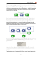
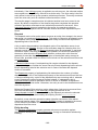
The project for this process is constructed in two stages. First, the machine section
will be constructed, including the failure and repair arrangement. In the secondly
stage the technician resource will be implemented, together with the additional duties
for the technician. For the first stage, start a new case and create the project section
as displayed in the figure.
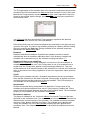
Assign the following server properties:
PartsSupply:
Timing =1.2
Storage:
Capacity = 5
Failure:
Timing = 100
Repair:
Timing =10
Machine:
Integrated dispatch
- 21 -
Renque user's guide
Assign the following link properties:
Storage-Lost:
Overflow recipient
Machine-Lost:
Discard recipient, Escort, Independent
The project created thus far includes the machine with supply of parts and the
storage area, as well as failures and the resulting loss of parts and reparation. The
server names reflect the function in the project. The PartsSupply server creates a
flow of entities, which represent the parts to be processed. The parts are stored in
the Storage server. The Machine server collects the parts from the Storage server
and sends them to the Done server, after applying a delay to act for the processing
time. The link from the Machine server to the Lost server is excluded from the regular
dispatch routine of the Machine server, because of the combined application of the
link properties Escort and Independent. The Escort property prevents this link from
being selected for dispatch by the Cycle Dispatch Rule. As a result, under normal
operation conditions, the entities representing the parts are all sent to the Done
server. The Independent property of the other link prevents the creation and release
of escort copies of the dispatched part entity to the Lost server.
The breakdown and repair actions for the Machine server are effectuated through
scripting. To implement these actions, create two incident scripts as shown in the
figure below.
The Enabled function called in the first script affects the Disabled property of the
Machine server. Disabling a server causes it to discard all stored entities and stop
operating. If a Disabled server is enabled, it will resume normal operation by starting
a new collection routine. The release of an entity from the Failure server disables the
Machine server by the action of the first script. Parts that are consequently ejected
from the Machine server are sent to the Lost server, because of the application of the
Discard recipient property to the link connecting the Machine server to the Lost
server. The failure entity is subsequently contained in the Repair server for a time
period corresponding to the repair time. When released, the entity is sent to the
destructing link, which re-enables the Machine server through the second script. The
object description Repair [1]-<delete> refers to the destructing-type link of the Repair
server. The script enables the Machine server, after verification that there no new
failure entities have arrived.
During repair, the Machine server is Disabled and will therefore not collect any new
entities. Because new parts continue to arrive, the capacity limit of the Storage server
is reached after some time. Entities arriving when the Storage server is full are sent
to the assigned Overflow recipient link, which is the link connected to the Lost server.
- 22 -
Renque user's guide
Before running the project, some modifications need to be made to the animation
properties of the project. First, the Storage server residents curve is modified to allow
display of all stored entities. Select the Modify curve item in the pop-up menu of the
Storage server to enter the curve edit mode. Drag the two rectangular control points
of the curve to reposition them as shown in the figure below. Click on an empty spot
on the Worksheet, somewhere away from the control points to apply the changes
and leave the curve edit mode.
Next, the travel animation needs to be disabled for some links. The simulation is
focused on the impact of failures on the production rate attained by the machine.
Because failures are relatively scarce, the animation will only be helpful if the
animation features are also concentrated on failures and repairs. In order to
accomplish this, select the set of server and link objects as displayed in the figure
below. This can be done easily by drawing a selection box from left to right, as
indicated in the figure, while keeping the left mouse button down. When the mousebutton is released, all objects inside the box are selected.
Double-click one of the selected objects, select the Display tab on the Link tab page
and check the Hide residents and Hide travels properties in the animation
properties frame.
Application of these options will prevent animation of entity traffic involved with
normal machine manufacturing, as all selected links are associated with normal
operation.
Run the project and view the animation. The Done server fills up rapidly and after
100 time units an entity is released from the Failure server. The entity stored in the
- 23 -
Renque user's guide
Machine server is released and travels to the Lost server. Then, while the Repair
server is occupied, the number of entities contained in the Storage server grows to a
total of 5, after which the Storage server also starts sending entities to the Lost
server. After some time the Repair entity is released and the arrival of entities in the
Done server continues. This scenario is repeated every 100 time units.
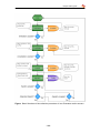
The next stage of this tutorial covers extension of the project with a shared technician
resource, with repairing and other duties. Add the server and link objects displayed in
the figure below. The connection order of links to a server can be altered by the
Move link connection sub-items of the pop-up menu, which appears upon a right
mouse click on a selected link.
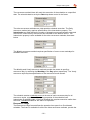
Assign the following server properties:
Failure:
Priority = 2
Repair:
Capacity = 2, Priority = 2, Shielding = 1, Revoking.
Technician:
Dispatch rule = Order, Priority = 2
JobsSupply:
Timing = 50, Priority =1
Jobs:
Timing = 10, Capacity = 2, Priority =1 , Shielding = 1,
Revoking shield.
Maintenance:
Capacity = 2, Timing = 30, Bonding consolidation,
Abortive interruption.
Assign the following link properties:
<create>-Technician:
Tracking
Technician-<all>:
Mandatory
<create>-MaintenanceSupply: Not Initializing
The Technician server represents a resource station. The server has a creating link,
which generates a single entity at the start of the simulation. The server has
dispatching links to the Repair, Jobs and Maintenance servers. These servers
represent an activity that requires a technician to proceed. They all have the Capacity
property value 2 and two collecting links. Of these, the top link is connected to the
- 24 -
Renque user's guide
server from which the entity representing the duty is received. The lower collecting
link has the Technician server as origin and has been assigned the Mandatory
property. As a result, the three servers will only load the activity entity if the
technician entity can be collected as well. On the dispatch side, the servers also have
two dispatching links with the default dispatching-related properties. When the
storage period elapses, the Cycle dispatch routine sends the first entity stored, which
is the entity representing the duty, to the top dispatching link. This link is a
destructing link, such that the duty entities are destroyed. The resource entity is sent
to the second dispatching link, which returns the entity to the Technician server. This
construction effectively causes the resource entity to be recycled, and forces the duty
servers to compete for it. The priority values are assigned to determine the
processing order if duty entities arrive at the same time. The Order value for the
Dispatch rule property of the Technician server also arranges resource allocation
priority.
To further enhance the animation, download a bitmap from the following web link:
www.renque.com/downloads/images/whiteball.bmp and save it on your hard disk.
The picture will be used to portray the resource entity. Double-click the Worksheet,
and create a new picture component by selecting the New/Picture item of the pop-up
menu of the Component repository. In the file selection utility that appears, select
the downloaded bitmap file and press Open. Select the Component tab and click
the small background area of the bitmap in the Picture preview box, in order to
select the bitmap background color as transparency mask color.
The maintenance work is to be performed at predetermined, scheduled times. Let’s
assume that the interval times are 50, 60 and 70 time units, in a repeating manner. In
Renque, this can easily be modeled using a schedule component. Create a new
schedule component by the New/Schedule item of the pop-up menu of the
Component repository.
- 25 -
Renque user's guide
The new schedule, with the schedule lines to be added, is displayed in the figure
below.
The schedule has three identical scripts:
MaintenanceSupply.Links("c").Item(1).EntityCreate
The script forces the creation of a single entity on the creating link of the passive
MaintenanceSupply server. This entity will be stored in the server for collection by the
Maintenance server. Type or copy/paste this script in the schedule grid, type in the
timing values given in the figure, and check the Cyclic property. The timing column
of the schedule grid defines the simulation times for execution of the schedule
scripts. The assumed repeating interval times (50, 60, 70) require execution of the
script at simulation time values 50, 110, 180, 230, 290, 360...and so on. The Cyclic
property forces execution of the schedule to recommence from the top row after the
last item in the list has been executed, and thus results into the desired time
intervals.
Next, create two new incident scripts as displayed in the figure below.
The retract statement, called on the Technician server, causes entities created by a
creating link under application of the Tracking property, to return to the link that
created the entity. The Icon assignment script assigns the picture component named
whiteball to the icon property of an arriving entity. As only the technician resource
entity arrives on this link, the resource entity will be distinguishable from other entities
in the animation.
Now, run the project with the animation enabled. Watch the technician entity being
collected by the Maintenance, Jobs and Repair servers. The technician entity is
stored together with the duty entity in the server and sent back to the Technician
server after processing. (If these servers do not display both entities on the residents
curve, zoom-in on the viewport using the middle mouse-button while holding down
the Ctrl key.)
- 26 -
Renque user's guide
To complete the project, place a new graph server on the worksheet. Double-click
the server and create a variable component named R. Set the Style property of the
graph server to Time-series line chart, and add a Data series for the current value of
variable R, by drag-dropping the variable component onto the series grid of the
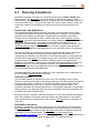
series tab page. Also, create a new Arrival incident script for the Storage server:
R = Lost.Population / (Done.Population + Lost.Population)
This script evaluates the “scrap ratio”, i.e. the fraction of lost parts with respect to the
total number of parts supplied, which is a measure for the performance of the
machine. The result is stored in variable R, which is plotted in the chart.
Finally, a small project extension is added to return the discarded maintenance duty
entities to the Maintenance server for completion of unfinished maintenance work.
Create an attribute component named Tresidual, and a new link as shown in the
figure. The link should have the properties Escort, Independent and Discard
recipient.
Also add two incident scripts to the Maintenance server:
Timing incident
If .SelectedCollectingLink.DestinationIndex =
1 then .Timing = 30 else .Timing = Tresidual
Remove incident:
Tresidual = ScriptEntity.Departure - SimTime
The second script assigns the remaining residence time to the Tresidual attribute of
the duty entity when it is discarded by the Retract call. The first script assigns the
attribute value of the duty entity to the server timing property if the duty entity is
collected from the recycle link. With this extension, the Maintenance server will also
process interrupted maintenance work.
Restart the simulation with animation enabled. At the simulation time value 200 a
failure occurs while the resource entity is stored in the Maintenance server. The
release of the failure entity from the Failure server causes a Retract call on the
resource entity. The retraction removes the resource entity from the Maintenance
server and sends it back to the Technician server. Because the Bonding
consolidation option is applied to the Maintenance server, the duty entity is discarded
to the recycling link. In case the technician resource is held by the Jobs or by the
Repair server, the retract call is ineffective, because these servers have a Shielding
value 1, which outweighs the argument 0 of the Retract script statement. The
Revoking property of the servers cancels the retraction call. As a result, the work is
postponed until the resource entity becomes available again in the Technician server.
- 27 -
Renque user's guide
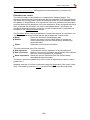
Now turn off the animation and let the simulation run for a while. The line in the chart
shows abrupt changes in the slope each time a failure occurs. As the simulation
proceeds, the “scrap fraction” R converges slowly to a value of about 0.05. Also click
the Tools/Runtime errors item of the Menu bar to open the Runtime error viewer.
The Runtime error viewer displays an error caused by the Leave incident script of the
Storage server. This error is caused by the division operation of the script, as both
the Done and the Lost server are empty the first time the script is executed. In
Renque, all script errors leave an entry in the Runtime error viewer, without causing
the simulation to halt. The occurrence of this particular error is easily prevented. It
was caused intentionally in this tutorial to demonstrate the function of the Runtime
error viewer.
The use of random numbers has been omitted in this tutorial in order to make
interpretation of the animation a little easier. If the project was for real, it would
probably incorporate several distribution components, generating significant random
variation. Even so, simulation models like this tutorial project are widely used for
parameter sensitivity analysis and system optimization. The number of resources, the
resource allocation priority, and the timing properties of servers and schedules may
all be varied to obtain quantitative insight into how the machine performance can be
improved by adjusting the conditions in the factory.
- 28 -
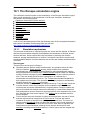
Renque user's guide
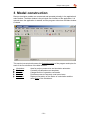
3 Model construction
Renque simulation models are constructed and operated primarily in the application's
main window. The Main window is the principal user interface of the application. It is
opened when the application is started, and the program exits when the Main window
is closed.
This section has a topic discusses the Operation basics of the program and topics for
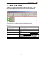
each of the five elements of the Main window:
Worksheet
Toolbox
Menu bar
Toolbar
Status bar
Area for project construction and simulation animation.
Contains pre-defined server templates.
Categorized list of operation commands.
Provides access to frequently used menu items.
Displays information on the status of a simulation and the
active layer of the Worksheet.
- 29 -
Renque user's guide
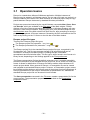
3.1 Operation basics
Renque is a stand-alone Microsoft Windows application. Multiple instances of
Renque may be started in a Windows session, but you can only have one project in a
Renque instance at the same time. Most elements of a Renque project may be copypasted between Renque instances by standard Windows procedures.
Projects are opened and saved by the usual Windows commands New, Open, Save
and Save As, which are available in the File menu of the Main window. Doubleclicking a file with a Renque-associated file extension in Windows Explorer will open
the file in a new Renque instance. Drag-dropping a file from Windows Explorer onto
the Worksheet area of the Main window will open the file, after prompting to save the
project being replaced. A Renque instance is closed by the Exit command on the File
menu or by clicking on the ‘X’-button on the title bar of the Main window.
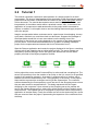
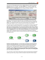
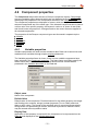
Renque project file types
There are two Renque project file types:
The Renque project file (extension: *.rnq, icon:
)
The Renque presentation file (extension: *.rnqp, icon:
)
The Renque project file is the standard Renque project file type, recognized by the
file extension rnq. This file type supports storage of all information that can be
contained in a Renque simulation project, including bitmaps, embedded
spreadsheets and all simulation data. This file type is either saved in text format or in
binary format, depending on the Settings applied in the Files preferences.
The Renque presentation file has the default extension rnqp. It contains essentially
the same information as the standard Renque project file, but is saved in a binary file
format. It allows for distribution of Renque simulation models without disclosure of
certain project details. When opened in Renque, a Presentation file can be viewed
and operated as a standard Renque project. However, a Presentation project cannot
be modified and the designer can prevent parts of the project from being displayed. A
Renque presentation file can only be saved back as presentation file, whereas the
standard Renque project file can be saved in both formats.
The Save presentation command in the File menu creates a presentation file for the
current project. The presentation properties are controlled on the Presentation
properties console.
- 30 -
Renque user's guide
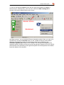
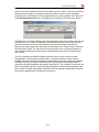
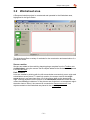
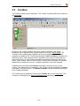
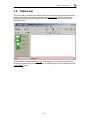
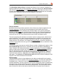
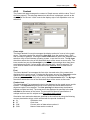
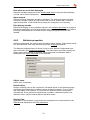
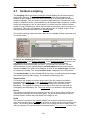
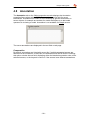
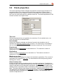
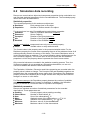
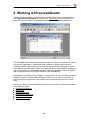
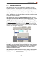
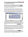
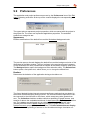
3.2 Worksheet area
A Renque simulation project is constructed and operated in the Worksheet area,
highlighted in the figure below.
The Worksheet offers a variety of methods for the construction and examination of a
simulation model.
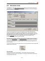
Server creation
Servers are added to the model by drag-dropping a template from the Toolbox onto
the Worksheet, using the mouse. Server objects added to the Worksheet are placed
in the current layer.
Link creation
Links are created by clicking with the left mouse button successively on an origin and
a destination server picture. To start link creation, the mouse must hit the origin
server picture in an area closer than 1/3 of the picture width to the downstream
edge. Clicking anywhere on the picture of the destination server will create the link,
unless the Ctrl key is held down. If the pictures are clicked on in a transparent region
the action has no effect. Links cannot be connected to Resource servers. Link
objects created on the Worksheet are placed in the current layer.
- 31 -
Renque user's guide
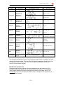
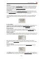
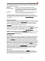
Link curve types
Renque supports the link curve types Spline, Polygon and Orthogonal, which all have
a distinct shape.
When a new link is created, the curve type is determined by the selected Curve type
item in the Format menu. The path of a curve is determined by control points, which
are visible only when a curve is being edited or created. When a link is being created,
each click on an empty spot on the Worksheet results in addition of a control point.
The curve types exist for animation purposes only: they have no logical distinctions.
Once created, curves can be edited to add, remove and rearrange control points, and
to change the curve type.
Object selection
Making changes to an object on the Worksheet first requires selection of the object.
Selected objects on the Worksheet are indicated by the select status color of the
operating system for the picture, label and curve of the object (for links only the
curve).
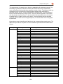
Selection of a single object is simply done by clicking on it in the Worksheet. The
selection result depends on the status of the Ctrl key and the Shift key on the
keyboard during the selection operation.
Shift key state
released
pressed
released
Ctrl key state
pressed
released
released
Selection result
remove from selection
add to the selection
start new selection
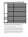
To select/unselect several objects at the same time: Press the left mouse button on
an empty location on the Worksheet and move the mouse while keeping the mouse
button pressed. A rectangle is displayed to indicate the active region. The selection
operation is executed when the mouse button is released. The result of this
rectangular selection depends on the horizontal sweep direction. If the mouse was
moved from left to right, only objects that lie completely inside the rectangle are
affected. If the mouse is moved from right to left objects touching the rectangle are
selected as well. The rules of the Ctrl and shift key status apply to this selection
method in the same manner as to selection by mouse clicks.
If the mouse button is held down for at least half a second on a set of overlapping
server pictures or identical links, the mouse pointer will change briefly to indicate that
a list of overlapping selectable objects has been assembled. The list is displayed on
the Worksheet when the mouse button is released. The selection status of the listed
objects can be adjusted by selecting and unselecting items in the list. If the
Worksheet is clicked again, the operation is applied and the list is removed.
- 32 -
Renque user's guide
In the Runtime display mode, objects can only be selected on the Worksheet if at
least one object element that indicates the selection status is displayed. Thus,
servers cannot be selected in the Runtime display mode if only the residents count is
visible, and links cannot be selected if the link curve is hidden. Selecting an object
that has been grouped with other objects, will select all members of the group,
including objects that cannot be selected individually.
Object transformations
The following transformations can be performed on objects visible in the Worksheet,
using the Menu bar or a pop-up menu on the Worksheet:
Cut, copy & paste.
Delete.
Group objects to enable joint selection.
Merge objects into a Fusions.
Rearrange server locations.
Resize servers.
Change the display order of servers.
Assign an object layer.
The position of servers on the Worksheet can be changed by dragging their picture
across the Worksheet. If the control-button on the keyboard is pressed while starting
the drag operation, the selected servers and selected connected links are duplicated.
In that case, the duplicates are subjected to the drag operation. As opposed to the
copy/paste menu commands, this duplication method does not store the objects in
the Windows clipboard.
Server editing
A Server can be resized using the Resize command of the Format menu. This
command is enabled if a server object has been selected by a mouse click. The
Resize command switches the Worksheet to the server resize mode. In the resize
mode, sizing handles are displayed on the edges of the server picture bounding box.
Servers are resized by dragged the sizing handles with the mouse. In the resize
mode for graph servers also allows adjustment of the Graph server layout. The
server resize mode is terminated if the worksheet is clicked at dome distance from
the sizing handles.
Curve editing
Link curves and server residents curves may be edited using the Modify curve
command of the Format menu. This command is enabled if a link or server object
has been selected by a mouse click. The Modify curve command switches the
Worksheet to the curve edit mode. In the curve edit mode the control points of a
curve are displayed on the Worksheet. A control point can be selected by the mouse
and dragged to a different position on the Worksheet by. Pressing the Delete key
removes the selected control point. Control points are inserted into a curve by
clicking on the link at the desired insertion location, while keeping the Ctrl key
pressed. The type of the curve being edited is changed by selecting another Link
type item in the Format menu. The curve modifications are stored and the curve edit
mode is terminated by pressing the Enter key or by clicking on the Worksheet at
some distance from the curve being edited. Pressing the Esc key terminates the
curve edit mode without storing any changes made to a curve.
Viewport transformations
The viewport dimensions of the Worksheet may be scaled and translated using the
mouse. The viewport is translated if the mouse is moved while keeping the middle
button pressed. The same procedure results into dynamic scaling of the viewport if
the Ctrl key is held down. On systems that have no middle mouse button, dynamic
- 33 -
Renque user's guide
scaling and translating of the viewport can be performed in the same manner, but
with the right button, while holding the Shift key down.
Runtime display mode
If a simulation is running, the display style of objects on the Worksheet can be
different form the objects display style in the Reset status. In the Running status, the
server Caption property is shown in the place of the Name property, and graphical
elements of servers and links can be hidden on the Worksheet on the Display tab of
the Object properties console. Enabling the Runtime display mode forces the display
style of Running status to the Worksheet at all times. The Runtime display item on
the View menu toggles between the normal and Runtime display modes.
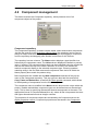
Fusions
A set of objects on the Worksheet can be merged into a Fusion server object. The
result of this operation is that the merged objects are no longer individually present
on the Worksheet, but represented collectively by the Fusion server. Fusions are
shown on the Worksheet in the same way as other server objects. Fusions have a
distinct default picture, which has the same style and size as the pictures of the
Active and Passive templates in the Toolbox.
Fusions are created by the Fuse objects command of the Format menu and
removed by the Unfuse command. The Fuse command merges all selected objects
on the Worksheet into a new Fusion server. The Unfuse command reverses this
transformation for all Fusion servers selected on the Worksheet.
Fusion window
The constituents of above-mentioned fusion server type can be made accessible in a
separate Fusion window. Fusion windows is opened by selecting the Open Fusion
windows command of the Window menu. The Fusion window displays all objects
that make part of the fusion server. The user interface of the Fusion window is highly
similar to the Main window user interface. Some menu items of the Main window that
are not relevant to fusion servers, have been left out of the Fusion window interface.
The fusion constituents and their arrangement can be modified in the Worksheet of
the Fusion window by the same methods as discussed in this section for the Main
window. The fusion window also supports all animation features. A link that is
connected to a fused operative server, but not fused itself, is shown connected to the
fusion server.
Layers
The server and link objects on the Worksheet are organized in layers. The layers
have a specified color, and may be locked and hidden. The main purpose of layers is
to collect together a series of objects that are related in some meaningful way, for
example by a common function in the model. The organization of a project into layers
offers many advantages to the project designer. The ability to hide layers and to
apply different colors to layers makes it easier to visualize objects collectively.
Furthermore, layer locking is useful, for example, for large server pictures, used as
background image, because objects in locked layers cannot be selected in the
Worksheet.
- 34 -
Renque user's guide
New objects created on the Worksheet are placed in the layer that has been
assigned active layer. The active or current layer can be identified in the Status bar
and by the color of the default templates in the Toolbox.
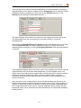
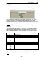
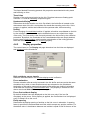
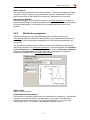
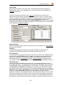
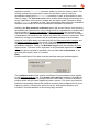
The layers of a Renque project are managed by the Layer list. The Layer list is
activated by a mouse click on the left-most panel of the Status bar or by the Layers
command of the Tools menu. The Layer list is a pop-up control that presents a list of
all layers defined for the project. It enables the creation and deletion of layers,
modification of layer properties, and assignment of the current layer. It is also used to
move objects on the worksheet to a different layer.
The radio button icon in the first column of the Layer list indicates which layer is the
current layer on the Worksheet. The radio button icon moves to another row if the
first column is clicked with the mouse, which sets the current layer. The second
column, labeled Name, displays the layer name. The layer name can be edited incell, by double clicking the name field or by pressing a key on the keyboard. The
assigned name must be unique and has the same format requirements as the Name
property of servers and components. The column labeled Color determines the
default display color for objects contained in the layer. The layer color can be
modified by a color selection utility, which is activated by clicking on the Color
column. The two other columns display indicate additional layer properties by icons.
The checkbox icon signifies that the layer is visible. Objects contained in hidden
layers are not shown on the Worksheet, The padlock icon signifies that the layer is
locked. Objects in locked layers are visible, but cannot be selected. Clicking either of
the two leftmost columns toggles the corresponding layer property.
The Set object layer button appears on the Status bar when the Layer list is
activated. By pressing this button, all selected server and link objects on the
worksheet are placed in the selected layer in the Layer list. The button is disabled if
multiple layer are selected in the Layer list.
Upon a right click on the list, a pop-up menu is shown, which has the following
commands:
New Layer
Creates a new layer.
Select all
Selects all layers.
Delete
Deletes the selected layers.
Sort
Sort the list alphabetically
Move
Moves selected item in the list up or down.
While the layer tool is visible, the window's Menu bar & Toolbar are disabled, as are
all other Renque windows. The Layer tool is deactivated by clicking on the
Worksheet, or pressing the Escape key on the keyboard.
- 35 -
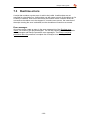
Renque user's guide
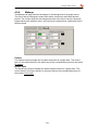
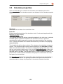
3.3 Toolbox
The Toolbox contains server templates. The Toolbox is used to add server objects to
the Worksheet.
At start-up, the Toolbox contains the Active, Passive, Resource and Graph
templates, which represent basic implementations of Renque server types. The
Toolbox is user-configurable by adding and removing templates. User-defined
templates are added to the Toolbox by selecting the Add to Toolbox command from
the pop-up menu, which appears when a selected server object is clicked with the
right mouse-button. A user-defined template inherits all properties from the source
server, when created. When is server object is created from a template, all template
properties are copied to the server. Templates properties cannot be changed.
Templates are removed by the Remove command in the pop-up menu of the
Toolbox. The display order of templates in the Toolbox can be modified by the Move
command in the pop-up menu. The Restore defaults command restores the original
set of Toolbox templates.
The Toolbox may be hidden by checking the Toolbox item on the View menu. The
Toolbox is not displayed if a Renque presentation file has been opened.
- 36 -
Renque user's guide
3.4 Menu bar & Toolbar
The Menu bar is found right underneath the title bar of the Main window. It has a
range of commands grouped into drop-down menus, which are indicated by the
words File, Edit, View.... The most frequently used Menu bar commands are also
available as a button on the Toolbar.
The available Menu bar commands are listed below, together with the corresponding
Toolbar button icon, if available, and a brief description of their function.
File menu
New
Open project
Starts a new project and discards the current.
Opens a project file.
Save project
Saves the current project.
Save project as
Saves the current project after prompting for a file
name.
Saves the current project as Renque Presentation
file.
Saves the Embedded worksheet of an opened
project file as a separate file. Available only if the
spreadsheet has failed to open in its application.
Closes the application without saving.
Save presentation
Extract spreadsheet
Exit
- 37 -
Renque user's guide
Edit menu
Undo
Redo
Cut
Copy
Paste
Paste special
Delete
Spreadsheet import
Find
Select
Unselect
Preferences
Undo the last mutation to the project. Clicking on the
drop-down arrow opens a mutations list to select an
item from.
Redo the last undone mutation to the project.
Clicking on the drop-down arrow opens a list of
undone mutations to select an item from.
Removes selected objects from the Worksheet and
stores them in the Windows clipboard.
Copy the selected objects the Worksheet to the
Windows clipboard. Also available as pop-up
command on the Worksheet.
Paste objects from the Windows clipboard to the
Worksheet. Also available as pop-up command on
the Worksheet.
Paste from the Windows clipboard with options for
the number of duplicates and the position of the
pasted objects on the Worksheet.
Delete objects selected in the Worksheet.
Import server, link and component objects from a
keyword list in the Embedded worksheet.
Opens the Search utility to select servers by string
comparison.
Selects specific object types in the Worksheet.
Unselects specific object types in the Worksheet.
Opens the Preferences utility to change preference
settings of the application and the project.
View menu
Presentation mode
Runtime display
Activates the presentation mode when checked,
forcing the program to treat the current project as
Renque Presentation.
Toggles the Runtime display mode.
Extend scale
Rescales the viewport to fit the entire model.
Scrollbars
Determines when the Worksheet scrollbars are
displayed. Selecting the Auto option displays the
scrollbars only if the model does not fit into the
viewport.
Hides the Toolbox when unchecked.
Hides a specific toolbar when unchecked.
Toolbox
Toolbars
- 38 -
Renque user's guide
Insert Menu
Creative links
Destructive links
Adds a creating link to all selected servers on the
Worksheet. Also available as pop-up command on
the Worksheet.
Adds a destructing link to all selected servers on the
Worksheet. Also available as pop-up command on
the Worksheet.
Format Menu
Curve type: none
Disables link creation.
Curve type: Orthogonal
Selects the orthogonal curve type for new links or
curves being edited.
Selects the polygon curve type for new links or
curves being edited.
Selects the spline curve type for new links or curves
being edited.
Switches to the Curve edit mode. Also available as
pop-up command on the Worksheet.
Switches to the Server resize mode. Also available
as pop-up command on the Worksheet
Places selected servers on top of the display order.
Curve type: Polygon
Curve type: spline
Modify curve
Resize
Bring to front
Send to back
Group objects
Ungroup objects
Fuse objects
Unfuse fusion servers
Align
Places selected servers at the back of the display
order.
Joins the selected objects in the Worksheet into a
group, forcing subsequent joint selection of all group
members.
Breaks up all selected groups in the Worksheet.
Merges selected objects in the Worksheet into a
Fusion server, represented by a single picture.
Breaks up a Fusion server into its constituents.
Opens the Alignment utility which allows
organization of the alignment of selected server
objects.
Tools menu
Object properties
Simulation clock
Opens the Object properties console, as will doubleclicking the Worksheet.
Opens the Clock properties Window.
Layers
Activates the Layer list.
Runtime errors
Displays the Runtime error viewer.
Event viewer
Displays the Event viewer window.
Spreadsheet application
Opens or displays an Embedded spreadsheet.
Data associations
Opens the Data associations manager.
- 39 -
Renque user's guide
Presentation properties
Opens the Presentation properties console.
Statistical analysis
Opens the Statistical analysis console.
Run menu
Reset
Restart
Pause
Animation
End replication
Run experiment
Reset experiment
Refresh
Resets the current simulation run, discarding all
simulation data.
Starts a new simulation run, or restarts the current
experiment.
Pauses or resumes the current simulation
replication.
Toggles animation on and off.
Ends the current replication, preserving all
replication data.
Completes the simulation run of the current
experiment, after which the Paused status is
assumed. Only available if the simulation has
multiple experiments.
Resets and discards all data of the current
experiment. Not available for the first experiment in a
simulation.
Repaints the Worksheet.
Window menu
Set background
Arrange windows
Fusion windows on top
Graph windows on top
Open Fusion windows
Close Fusion windows
windows list
Changes the background color of the Worksheet.
Opens the Window arrangement utility.
Moves Fusion windows on top of other Renque
windows.
Moves Graph windows on top of other Renque
windows.
Opens the Fusion window for all selected fusion
servers on the Worksheet. Also available as pop-up
command on the Worksheet.
Closes the Fusion window of all selected fusion
servers on the Worksheet.
Presents a list of all Fusion window titles. Clicking on
a list item activates the corresponding window.
Help menu
Getting started
Renque help
Renque website
Check for updates
Opens the Getting started section of the help
document.
Opens the help document.
Opens the Renque website in the default internet
browser.
Connects to the internet and checks if a more recent
Renque release is available for download.
- 40 -
Renque user's guide
About
Displays the application identifier panel. Click the
panel to close it.
There are two items on the Toolbar that are not available on the Menu bar:
Animation speed slider
The Animation speed slider controls the animation speed. Moving the indicator to the
right will speed-up the animation.
Zoom button
The Zoom button enables scaling of the viewport by a zoom factor specified by a
mouse operation. If the button is pressed and the left mouse button is kept pressed
while dragging the mouse over the Worksheet a rectangle is drawn of the same
aspect ratio as the Worksheet, centered around the position where the mouse-button
was pressed on the Worksheet. The size of the rectangle indicates the viewport
scaling factor applied when the mouse button is released. The scaling direction
depends on the direction of the mouse displacement. If the mouse was moved from
left to right the viewport scale range is decreased to the rectangle area scale range. If
the mouse button was moved to the left, the viewport is expanded to the range that
results from shrinking the Worksheet area to fit the rectangle area. For a small
mouse displacement, the viewport zoom factor remains unchanged and the center of
the viewport is translated to the mouse location.
- 41 -
Renque user's guide
3.5 Status bar
The Status bar is located at the bottom edge of the window and is divided into three
panels. From left to right, panel 1 displays the current layer, panel 2 displays the
simulation state and panel 3 displays the current time in the simulation in a userspecified format.
Clicking panel 1 activates the Layer list. Clicking panel 3 activates a text field that
contains a format string for time display. The format string cay be modified to set the
Time display format.
- 42 -
Renque user's guide
4 Object properties
The Object properties console provides access to properties of server and link
objects on the Worksheet. The console also manages component objects of a
Renque project, and simulation results are reviewed primarily on this console.
The controls on the window are organized in outlined frames, which provide access
to different property categories of different object types. A tab strip located at the top
of window determines which frames are displayed on the window.
This section has an introduction topic describing general operation of the console, a
topic that deals with components, and topics for each item of the main tab strip:
General operation
Component management
Server properties
Link properties
Graph properties
Component properties
Incident scripting
Annotation
Simulation data
- 43 -
Renque user's guide
4.1 General operation
The Object properties console is opened by the Object properties command on the
Tools menu or by double-clicking the Worksheet.
Context worksheet
The window can be opened from the Main window and from a Fusion window. The
window from which the console is opened represents the context worksheet of the
console. The console only displays properties of server and link objects that have the
selected state in the context worksheet. If the selected objects do not have a uniform
value for a specific property, the keyword <various> is displayed in text fields, check
boxes are grayed out, and combo boxes are left empty. In general, control items on
the console are disabled or hidden if there are no selected server objects that are
affected by the controlled property. Alteration of object properties by the control items
on the console is applied to all selected objects.
Simulation state context
Many object properties presented on the Object properties console can be changed
by scripting during a simulation run. The simulation state context of the Object
properties console determines whether the current value or the initial Reset status
value is displayed for such properties. The control items that are affected by the
Simulation state context are organized in frames, as indicated in the server, link and
distribution property topics. The Simulation state context is set by a pop-up menu,
which appears upon a right-button mouse click on these frames.
In the Reset status of a simulation, the control items on the pop-menu are all
disabled and the Display initial values item is preselected. If the simulation is not in
the Reset status, the Display current values item can be selected, which forces the
display of property values in the current simulation state. By default, changes made
on the console to a property are applied to both the initial an the current value of
property. If the Modify current only option is checked, the initial value remains
unchanged. Changes made to the model under application of the Modify current
only option can not be undone in the Edit menu.
- 44 -
Renque user's guide
The Worksheet objects frame, located at the bottom of the console, catalogs the
objects contained in the Context worksheet. The frame encloses the Server browser
and either the Link browser or two Routing list boxes. The latter are shown if the
Context worksheet has a single selected server and all selected links are connected
to that server. Otherwise, the Link browser appears in the frame.
Server browser
By default, the server browser presents a list of the server objects contained in the
Context worksheet. The servers are represented by their Name and Picture
properties. The latter also indicates the selection status in the context worksheet.
Servers in hidden layers are excluded from the list. The text field positioned above
the browser may be used to specify a pattern matching string. Server objects are
removed from the list if their Name property does match the pattern string.
The main purpose of the browser is to make it easier to assign server references to
object properties. This is done by drag-dropped server objects in the browser onto
other controls of the console, such as a text field or grid cell. You cannot create or
delete servers in the browser, nor change the selected state of servers. Selection of
a server in the browser does not give the object the selected state, as selection in the
Worksheet does.
The browser has a pop-op menu which offers a number of display style options. If the
Sort alphabetically menu item is checked, the servers are listed in alphabetical
order, instead of the default Worksheet z-order sorted listing. Checking the Show all
option includes servers which are not displayed on the Context worksheet because
they are merged into Fusion servers. Such servers are displayed by the fusion path
name, such as the label Fusion1/Server1 for the server named Server1, which is
fused into fusion Fusion1. Application of the Hide fusion path removes the fusion
path again. The Show all and Hide fusion path options also affect the display of link
objects in the below-mentioned Link browser.
Link browser
The link browser, which is found adjacent to the above-mentioned Server browser,
presents a list of the link objects in the Context worksheet. The links are depicted by
a standard icon, of which the color indicates the selection status of the link in the
Context worksheet. The two columns of the browser display the name of respectively
the origin server and the destination server, both accompanied by the index of the
connection order to that server, enclosed in parentheses. The Link browser has the
same function for links as the above-mentioned Server browser has for servers.
- 45 -
Renque user's guide
Routing list boxes
These items presents the Link objects connected to a uniquely selected server in the
Context worksheet. The list box on the left-hand side displays the collecting links
connected to the selected server, and the list box on the other side displays the
connected dispatching links.
The routing list boxes can be used to create, delete and select links. Also, the link
connection order can be changed and the origin or destination servers can be
replaced by other servers. As for the above-mentioned Link browser, link items in the
routing list boxes may be drag-dropped onto other controls on the console, in order to
assign references to link objects. In contrast with the browser controls, selection of a
link in the routing list does affect the selected state of the link object in the Context
worksheet. Multiple link objects can be selected in either or both routing list boxes.
When the console is closed, the original selection state is restored, unless the link
was deleted.
The routing list boxes have either one or two columns. The first column displays a
marker symbol that characterizes the link type and its properties, followed by the
name of the origin or destination server. The meaning of the markers is given in the
table below.
Marker
Link type
Link properties
Active origin server
Active destination server
Passive origin with active destination
Passive origin and passive destination
Creating
Destructing
End marker style
Dispatching
Expiration, Overflow or Discard
Collection properties
Dispatch properties
Default
default
Mandatory
Escort
Solitary
Independent
Mandatory and Solitary
Escort and Independent
If the Collect rule of the server has the value Probability, the upstream routing list
displays the Collect weight of the links in a second column. The same applies for the
downstream routing list for the Dispatch weight, if the Dispatch rule has the value
Probability. The content of the routing list boxes is subject to the Simulation state
context,
- 46 -
Renque user's guide
A new link is created by dragging a server from the Server browser and dropping it
on an empty area in the routing list box. The dragged server becomes the origin or
destination server of the new link, depending on which of the list boxes is the drop
target. Links are inserted in the list if the server is dropped on a marker icon in the
first column. Alternatively, if the server is dropped on a server name, the origin or
destination server is replaced by the dragged server. Creating- and destructing-type
links are created using the <create/delete> item in the Server browser. The link
connection order may be changed by the Arrow buttons at the bottom of the
window. Links can be deleted using the Delete key or the Delete item command of
the pop-up menu of the routing list boxes.
- 47 -
Renque user's guide
4.2 Component management
This frame encloses the Component repository, which presents a list of all
component objects of the project.
Component repository
The Component repository is used to create, delete, select and rename components.
Just like the controls in the Worksheet objects frame, the repository can be used to
assign an object reference to a property of another object by dragging a component
from the repository and dropping onto another control item on the console.
The repository has two columns. The Name column displays a type identifier icon
followed by the component name. The Value column displays the default or primary
value, if existing. The component listing style can be moderated using the combo box
and the text field at the top of the frame. Selection of an item in the combo box
restricts component display to the selected component type. Entering a pattern
matching string in the text field removes all components from the list of which the
Name property does match the pattern string.
.
New components are created with the New component command of the pop-up
menu of the Component repository. This pop-up menu also has the usual items,
Copy, Paste and Delete item, as well as the Paste special command, which allows
for serial pasting of components from the Windows clipboard.
The component name is modified in the Name column and must be unique within the
project. Variable and attribute component types can be defined as one-dimensional
array. This is done by specifying dimensional bounds as argument to the name. The
appropriate format is ComponentName(lb to ub), where lb and ub represent the lower
and upper dimensional bounds as integer numbers.
The properties of component objects are accessed by the Component tab on the
Object properties console. Component properties as discussed in the Component
properties topic.
- 48 -
Renque user's guide
4.3 Server properties
The Server tab on the Object properties console presents properties of selected
Operative, Resource and Fusion server types. The Server tab displays the Server
type tab strip when selected. This tab strip directs to additional tab pages, which
present different property categories or specific properties of a server type. (The
properties of Graph servers are accessed on the Graph tab on the console). A server
type tab is hidden if no server of the corresponding type has been selected in the
Context worksheet.
4.3.1
General server properties
The General tab presents properties shared by different server types.
Name
Internal server identifier string. The Name property may contain a maximum of 255
characters in the ranges A-Z, a-z, 0-9 and the underscore _ symbol. The name
property must start with an alphabetic character and is case-insensitive. Server
objects have an index property that appears in the object Name if unequal to zero, as
a suffix number separated by a space character. The name part without the index
number is referred to as the root name. The root name must be unique to servers.
Indexing of the selected servers is done automatically. If a string without suffix is
entered in the text field, indexing of the selected servers starts from the highest index
number of all existing non- selected servers with the same root name. If a suffix is
specified in the text field, indexing starts with the specified suffix number. In both
cases, server indices of non-selected servers with the same root name are skipped in
the indexing procedure. All properties represented on the tab page are subject to the
Simulation state context, except for the Name property.
Caption
Server title as displayed in the Worksheet in the Runtime display mode. The caption
property can contain any character. The value <default> denotes that the Caption
property is identical to the Name property.
Timing
Determines the storage time for entities in active servers and the maximum
residence time and passive servers. Permitted values are real numbers >= 0 and all
evaluating component types. The Timing property is set to Void if the Timing text field
is left empty, which means that no timing is applied. In that case, no event is created
in the Event calendar for entity removal, both for active and passive servers. The
property is not available for resource and fusion servers.
- 49 -
Renque user's guide
Capacity
Maximum number of residents allowed in a server. Permitted values are integer
numbers >= 0 and the evaluating component types variable and distribution. The
Capacity property is set to Void if the Capacity text field is left empty, which means
that there is no capacity limitation. The Capacity property for Resource servers
determines the capacity for resources instead of entities. The property is not
available for fusion servers.
Priority
Determines the Priority value of calendar events generated by the server. Permitted
values are integer numbers in the range -16000 to + 16000 and evaluating
component of type variable and distribution. The property is not available for fusion
servers.
Disabled
Disables the server. A Disabled active server does not perform any simulation
actions and cannot store entities. Entities arriving at a Disabled passive server are
not accepted and are stored in the link buffer instead. Resource servers will not
allocate any resources when disabled. The property is accessed by scripting through
the Enabled scripting procedure. The property is not available for fusion servers.
4.3.2
Operative server properties
The Operative tab presents properties of Operative servers. The properties on this
tab page determine the way active and passive servers operate in a simulation
model. All properties represented on the tab page are subject to the Simulation state
context.
The frame labeled Collection presents server properties associated with collection of
entities in the operating mechanism of active servers.
Collect Rule
Determines the method by which a non-Mandatory link is selected in the verification
stage of the operating procedure of an active server. Possible values: Cycle (test
links in top-down order, starting from the link selected previously); Random (random
- 50 -
Renque user's guide
choice); Probability (weighted random choice dependent of the Collect Weight
property of the links); Order (test links in order, starting from the first link). The
evaluating component types variable and distribution can be assigned to the Collect
Rule property. In that case a link is selected by property evaluation of the assigned
component.
Integrated dispatch
Determines the actuation method of the collection procedure of active servers. By
default, a new collection procedure is started when the transfer stage of the previous
collection procedure is completed. If this property is applied, a new collection
procedure is not started until all entities collected by the previous collection
procedure have been dispatched.
Certified verification
Enables entity availability confirmation for incitation of the verification stage of the
collection procedure. By default, upon successful completion of incited verification,
entity collection moves forward to the transfer stage without confirmation of the
availability of the entities to be collected. If this property is applied, entity availability
is rechecked when a incited verification procedure is completed.
Bonding consolidation
Protects the collection procedure of active servers in the consolidation stage against
entity displacement. If this option is applied, entity bonding is performed on entities
consolidated by the server. If a bonded entity is displaced, it is either sent to the
bonding server or causes the bonding server to be interrupted.
Premature transfer
Enables entity transfer in the collection procedure of active servers prior to
completion of the consolidation stage. By default, transfer of entities is postponed
until all entities to be collected are available for transfer. If this property is applied, the
availability test is omitted and all available collected entities are transferred upon
consolidation.
Disordered transfer
Determines the order by which entities are transferred in the collection procedure of
active servers. By default, active servers transfer all entities to be collected for each
collecting link consecutively, in top-down order. Application of this property results
into transfer of entities in order of availability.
The frame labeled Processing presents server properties associated with storage in
and release of entities from servers.
Dispatch Rule
Determines the selection method of a non-Escort link in the dispatch routine of an
active server, and for incitation by a passive server. Possible values: Cycle (test links
in order, starting from the link selected previously); Random (random choice);
Probability (weighted random choice dependent of the Dispatch Weight property of
the link); Order (test links in order, starting from the first link). All evaluating
components types can be assigned to the Dispatch Rule property. In that case a link
is selected by property evaluation of the assigned component.
Passive Rule
Determines the sequence by which resident entities are retrieved from a passive
server in the collection procedure an active server. Possible values are FIFO (first-infirst-out), LIFO (last-in-first-out) and Random (random choice from then resident
entities). Evaluating components of type variable and distribution can be assigned to
the Passive Rule property. In that case an entity is selected by property evaluation of
the assigned component.
- 51 -
Renque user's guide
Discrete timing
Forces individual evaluation of the Timing property for entities stored in an active
server during transfer. By default, all entities stored during the collection procedure of
an active server are assigned a uniform Timing value. If this property is applied, the
Timing property is evaluated and applied for each individual entity stored in the
server.
Uniting
Forces merging of transferred entities. If applied, all entities collected by the
collection procedure of an active server are united into a single target entity. The
target entity is the first entity stored in the server. By default, the remainder of the
transferred entities are simply deleted, but their transfer does cause a Unite incident,
which permits customization of the uniting process by scripting. The Timing property
of the server is applied to the target entity after all collected entities have been
united. Note that link objects also have a Uniting property.
The frame labeled Extraction presents server properties associated with
entity displacement.
Shielding
Determines resistance against Interrupt and Retract scripting calls. Permitted
values are integer numbers in the range -16000 to +16000 and evaluating
components of type variable and distribution. The Level argument passed with the
Interrupt or Retract scripting statements is tested against the value of the
Shielding property. If the Level argument value is smaller than Shielding value, the
Interrupt call is overruled, and the result of the Retract call depends on the
below-mentioned Revoking property of the server.
Revoking shield
Determines the effect of a Retract scripting statement call, which is overruled by
the above-mentioned Shielding property. By default, the statement call is deferred
and retraction will be reattempted every time the entity is stored in a server. The
statement call is cancelled if this property is applied.
Preemptive capacity
Determines the response to a Capacity deficiency of a server. By default, a decrease
of the Capacity value of a server is ignored, and the number of residents is allowed to
surpass the Capacity value. An Overflow incident occurs if this property is applied
and the Capacity value becomes smaller then the number of residents.
Abortive interruption
Determines the effect of interruption on the collection procedure of active servers.
By default, interruption of an active server only causes adaptations in the collection
procedure of the server. If this option is applied, interruption aborts and restarts the
collection procedure of the server.
Interruptive timing
Causes a server interruption in response to a change of the Timing property during a
simulation. The Timing property can be altered by the Timing scripting command,
by cell content changes of a Property association, or manually in the Current value
Simulation state context on the console.
4.3.3
Resource properties
The Resource tab presents properties of Resource servers. The control items on this
tab page determine the number of resources to be allocated to active servers, and
- 52 -
Renque user's guide
the allocation method applied. Only the Requirement and Allocation Rule properties
on this tab are subject to the Simulation state context.
The frame labeled Display style contains two option buttons, which determine the
way resource allocation requirements are presented in the area underneath the
frame. Selecting the Server requirements button displays the Resource repository.
Selecting the Demand on resources button displays the below-mentioned Resource
demand grid instead.
Resource demand grid
The Resource demand grid shows the Allocation requirement properties of the
Resource servers with the selected state in the Context worksheet. The grid rows
represent positions in the allocation preference order. The name of the active server
of the allocation preference position is displayed in the Server column. The
Allocation requirement property of the allocation preference positions is shown in the
Requirement column. The keyword <various> is displayed if the selected resource
servers do not have uniform properties for a grid cell. If one of the selected resource
servers does not have an active server assignment for a particular position in the
allocation preference order, the keyword <incomplete> is displayed in the
corresponding cell of the Server column.
Active servers are added to the grid by dragging a server object from the Server
browser and dropping it onto on the empty area in the grid. If the item is dropped on
the server picture of an existing row, a preference position is inserted before the
target grid row. If the item is dropped on a grid cell in the Server column, the Server
object of the drop row is replaced. The Allocation requirement value can be changed
by typing a new value into a cell of the Requirement column. Permitted values are
integer numbers ≥ 0 and the evaluating component types variable and distribution.
Grid rows may be deleted using the Delete item command in the pop-up menu of the
list. The grid row order may be changed by the arrow buttons at the bottom of the
console.
Resource repository
This list presents all resource servers in visible layers of the project, sorted by
z-order. The column labeled Requirement denotes the Allocation requirement
property of the active servers with the selected state in the Context worksheet for the
Resource servers in the list. The keyword <incomplete> in the Requirement column
- 53 -
Renque user's guide
indicates one of the selected active servers does not have an allocation requirement
for the corresponding resource server. The keyword <various> indicates that all
selected active servers have an assigned allocation requirement, but with different
values (which may include the value 0). The keyword <none> indicates that none of
the selected active servers have an assigned allocation requirement.
The Allocation requirement property can be changed in the same manner as for the
above-mentioned Resource demand grid
Allocation Rule
Determines the selection method by which a resource server seeks active servers in
the Allocation preference order for incitation. Possible values: Cycle (test servers in
order, starting from the server last served); Random (random choice); Order (test
servers in order, starting from the top). Evaluating components of the types variable
and distribution can also be assigned to the Allocation Rule property. In that case
servers are selected on the basis of position in the Allocation preference order by
property evaluation of the assigned component.
4.3.4
Fusion properties
The Fusion tab presents properties of Fusion servers. The controls on this tab
determine the link connectivity of fusion servers and some options for data recording.
Fusion member browser
This browser is available only if a single fusion server has been selected. The
browser displays the server objects merged into the selected fusion. The browser
can be used to get a quick view of the fusion composition and to assign servers to
the Default origin server and Default destination server properties by drag-drop
operations.
Ignore residents
Disables resident entity bookkeeping for fusions. The resident entities of a fusion
server include all resident entities of the server and link objects merged into the
fusion, as well as entities traveling on merged links. The fusion residents are
registered by default. If this option is applied, resident registering is omitted, which
disables resident Animation and Data recording for the fusion.
- 54 -
Renque user's guide
Ignore residents nested
Disables resident entity bookkeeping for nested fusions, as the above-mentioned
Ignore residents item does for the selected Fusion servers. Clicking this option
disables resident entity bookkeeping for all fusions nested in the fusions represented
on the tab. The control is disabled if none of the selected fusion servers have nested
fusions, and grayed out if the nested fusions have a non-uniform value for the Ignore
residents property.
Default origin server
This combo box selects a fused server object to act as origin server for links created
with the Fusion server as origin, on the Worksheet that contains the Fusion server.
Available only if a single fusion server is selected on the Context worksheet.
Default destination server
This combo box selects a fused server object to act as destination server for links
created with the Fusion server as origin, on the Worksheet that contains the Fusion
server. Available only if a single fusion server is selected on the Context worksheet.
4.3.5
Display properties
The Display tab presents properties of all logical server types. The control items on
this tab page determine how the servers are displayed and animated on the
Worksheet. Only the Picture property on this tab page is subject to the Simulation
state context.
Hide residents; curve; picture; caption; residents count
Hides the indicated items if the Runtime display mode is effective.
Force animation
Pauses animation after and an entity is stored in the server and removed at the same
simulation time, while no zero-duration travels are animated on the Worksheet.
Application of this option ensures that stored resident entities are visible in animation
for at least the Zero timing Travel animation time. This property is ineffective if the
above mentioned Hide residents option is applied
Force first resident display
By default resident icons are displayed on the server curve only if the icon fits
completely on the curve. If applied, the first resident icon is displayed even if it
doesn't fit on the curve.
- 55 -
Renque user's guide
Joint collecting link ties; dispatching link ties
By default the curve connections are spread in vertical direction across the
connecting edge of the server picture. If the property is applied, the curves of
connected links are anchored to the server picture on a single location at the center
of the connecting edge.
Select by caption
By default selection of servers is possible only through the picture and resident
curve. If applied, servers can be selected also by the caption text region, provided
the caption is visible.
Entity spacing
Determines the display spacing of entities on the resident curves in animation. A
spacing factor is specified in the associated text field, which accepts any positive
number. For the default value 1 the distance between two entities is equal to half of
the sum of the maximum of the height and width of both entity icons. The entity
distance changes proportionally with the specified spacing factor value.
Font
the Font combo box sets the font style and size for display of the server on the
Worksheet. Clicking the drop-down arrow opens the Font selection utility, by which
font properties can be assigned in a prearranged manner.
Tooltips
The frame labeled Tooltip text contains a text field which specifies a text string, which
appears as Windows Tooltip if the mouse hovers over a visible server picture in the
Worksheet. If the Automatic box is checked, the text field is disabled, and a listing of
properties with non-default values is applied as tooltip for the object.
Picture
Sets the picture component of the selected servers. Type the name of the desired
item or select it from the combo box to change. The Picture preview box displays the
assigned picture component at a size corresponding to the default picture size. The
picture is displayed only if all selected servers have an identical picture property. The
picture property of the selected servers may be set by dragging a picture component
from the Component repository into the Picture preview box.
- 56 -
Renque user's guide
4.4 Link properties
The Link tab on the Object properties console presents properties of selected Link
objects. The Link tab page displays the Server type tab strip when selected. This tab
strip directs to additional tab pages, which present different property categories.
4.4.1
Operative link properties
The frame labeled Collection presents link properties associated with collection of
entities on the link in the operating mechanism of active servers.
Mandatory
Determines the role of the link in the verification stage of the collection procedure of
an active destination server. If this option is applied, the link is excluded from the link
selection procedure governed by the Collect rule of the destination server.
Solitary
Excludes links from collection in the verification stage of the collection procedure of
active destination servers. If applied to a Mandatory link, the link is excluded from the
collection procedure. If applied to the selected non-Mandatory link in the collection
procedure, all Mandatory links are excluded from the collection procedure.
Batch size
Minimum number of entities to be collected on the link in the collection procedure of
an active destination server. Permitted values are integer numbers >= 0 and the
evaluating component types variable and distribution.
Collect Weight
Probability weight factor for the non-Mandatory link selection procedure, as governed
by the Collect Rule value Probability. The default value is 1. Permitted values are
floating point numbers >= 0. Evaluating components of type variable and distribution
can also be assigned to the Collect Weight property.
- 57 -
Renque user's guide
Required availability
Number of entities available for collection on the link required to pass the verification
stage of the collection procedure of an active destination server. Permitted values are
any integer number, the Void value, and components of type variable and
distribution. By default, the property is Void and the text field is left empty. The Void
value signifies that the number of entities required is equal to the Batch property. A
zero value signifies that no entities are required, and a value smaller than zero
signifies the number of entities allowed short of the Batch property. Evaluating
components of type variable and distribution can also be assigned to the Required
property.
Excess permitted
Denotes the maximum number of surplus entities collected on the link in the
consolidation stage of the collection procedure of an active destination server. If
more entities are available for collection on a link than it's Batch value, this property
determines the number of entities collected in excess of the Batch size. Possible
values for this property are integer numbers and Void. If the text field is left empty the
property is Void, signifying that the number of excess entities collected is equal to the
available number of excess entities. The default zero value signifies that no excess
entities are collected, and a value smaller than zero signifies the number of excess
entities omitted from the entities available in excess of the Batch property. Evaluating
components of type variable and distribution can be assigned to this property.
Suspending
Postpones retrieval of entities from passive servers in the consolidation stage of the
collection procedure of an active destination server.
Claiming
Prevents entities consolidated by an active server from collection by another server.
If applied, consolidated entities are claimed if they are stored in the passive origin
server or in the buffer of a link to which the above-mentioned Suspending property is
applied. Claimed entities can also be bonded by the collecting server.
The frame labeled Dispatch presents link properties associated with the dispatch
routine of active origin servers of the link or with the reception of displaced entities.
Escort
Determines the role of the link in the dispatch routine of an active origin server. If
applied, the link is excluded from the link selection procedure governed by the
Dispatch rule of the origin server. In the dispatch routine, the dispatch entity is sent to
the selected non-Escort dispatching link, and copies of the dispatch entity are sent to
Escort links.
Independent
Excludes links from the dispatch routine. if applied to an Escort link, the link is
excluded from the dispatch routine. If applied to the selected non-Escort link, all
Escort links are excluded from the dispatch routine.
Departures number
Number of entities sent to a dispatching link in the dispatch routine. Permitted values
are integer numbers >= 0 and all evaluating component types. A zero value for the
selected non-Escort link causes the dispatch entity to be deleted, the default value 1
dispatches only the dispatch entity, and for higher values also copies of the dispatch
entity are sent. For Escort links, the Departures property signifies the number of
copies of the dispatch entity sent to the link.
- 58 -
Renque user's guide
Dispatch Weight
Probability weight factor for the non-Escort link selection procedure, as governed by
the server Dispatch rule value Probability. Permitted values are floating-point number
>= 0 and all evaluating component types.
Overflow recipient
Assigns a link as recipient for entities displaced from a server, causing an
Overflow incident. Only one Overflow dispatching link of a server can be designated
Overflow recipient. When this property is applied to a link, it is removed from all other
dispatching links of the origin server.
Expiration recipient
Assigns a link as recipient for entities displaced from a server, causing an
Expiration incident. Only one dispatching link of a server may be designated
Expiration recipient. When this property is applied to a link, it is removed from all
other dispatching links of the origin server.
Discard recipient
Assigns a link as recipient for entities displaced from a server, causing a
Discard incident. Only one dispatching link of a server may be designated Discard
recipient. When this property is applied to a link, it is removed from all other
dispatching links of the origin server.
The frame labeled Entity creation presents properties of creating links.
Initializing
Enables entity creation on a creating link at the start of a simulation replication. If
applied, a number of entities equal to the Batch property of the link are created at the
replication start and sent to the destination server. Upon arrival at the destination
server, the entities are stored in the server. Recorded statistics of the link and of the
destination server are reset when all initializing entities have been stored in the
destination server. For an active destination server, the Initializing entities are
subsequently dispatched without delay. The Initializing property has no function for
non-creating links.
Completing
Enables entity creation on a creating link in response to requests by upstream
connected active servers. This property has distinctive functionalities for links with
active and passive destination servers. For an active destination server the property
forces the link to create entities requested in the consolidation stage of the collection
procedure of the server. For a passive destination server the link produces as many
entities as requested by an active destination server of a dispatching link of the
passive destination server of the Completing link and not available as resident in the
passive server. A Batch size value of the Completing link greater than unity
generates surplus entities. Only one Completing collecting link can be assigned to a
passive server. When applied to a link, the Completing property is removed from the
other Completing collecting links of the destination server. The property has no
function for non-creating links.
Tracking
Enables entity retraction on a creating link. If applied, the location of entities created
on the link is recorded during a simulation. This information is used by the retraction
routine to extract entities from their current location.
- 59 -
Renque user's guide
The frame labeled Processing presents link properties associated with entity travel
and buffering on links.
Travel time
Duration of the entity travel period on the link. Permitted values are floating-point
numbers >= 0 and all evaluating component types.
Upstream buffering
Determines the buffer location on a link. By default, the link buffer is located on the
downstream side of the link, and entities are stored after traveling on the link. If this
property is applied, entities are buffered at the upstream side, before traveling.
Uniting
Forces merging of consolidated entities. If applied, all entities consolidated on the link
by the collection procedure of an active destination server are united into a single
unite entity. The unite entity is the first entity stored in the link buffer by the collection
procedure. By default, the remainder of the consolidated entities are simply deleted,
but do cause a Unite incident, which permits customization of the uniting process.
Note that active servers also have a Uniting property.
4.4.2
Display properties
The control items on The Display tab page determine how the links are displayed
and animated on the Worksheet.
Hide residents; curve; travels
Hides the indicated items if the Runtime display mode is effective.
Force animation
Pauses animation after an entity is stored in the link buffer and removed at the same
simulation time, while no zero-duration travels are animated on the Worksheet.
Application of this option ensures that stored buffer entities are visible in animation
for at least the Zero timing Travel animation time. This property is ineffective if the
above mentioned Hide residents option is applied
Force first resident display
By default resident icons are displayed on the link curve only if the icon fits
completely on the curve. If this property is applied, the first resident icon is displayed
even if it doesn't fit on the curve.
Entity spacing
Determines the display spacing of entities on the link curve in animation. A spacing
factor is specified in the associated text field, which accepts any positive number. For
the default value 1 the distance between two entities is equal to half of the sum of the
- 60 -
Renque user's guide
maximum of the height and width of both entity icons. The entity distance changes
proportionally with the specified spacing factor value.
Tooltips
The frame labeled Link tooltips contains a text field which specifies a text string,
which appears as Windows Tooltip if the mouse hovers over a visible link curve in the
Worksheet. If the Automatic box is checked, the text field is disabled, and a listing of
properties with non-default values is applied as tooltip for the object.
- 61 -
Renque user's guide
4.5 Graph properties
The Graph tab on the Object properties console presents properties of the selected
Graph servers. (The properties of other server types are accessed on the Server
tab.) At the top of the Graph tab page another tab strip is shown, which directs to
additional tab pages for graph servers. These tabs manage graph server properties
in different categories.
4.5.1
General graph properties
The General tab page manages the common graph server properties, which apply to
all graph server types.
Name
Name of the graph server.
Style
This combo box determines the primary display style of the graph server. The default
value Text is used to display text on the server. The displayed text is set on the
Content tab, and may include literal strings, simulation data and simulation clock
information. In addition, there are five alternative styles, which are used to display
different kinds of charts on the server:
Time-series line chart Data plot as a function of time.
Frequency histogram
Histogram of frequency intervals of property value
observations.
Column chart
Column chart of current property values.
Replications histogram Histogram of frequency intervals of final parameter
values for replications. This graph style requires
enabled statistics recording for the Series objects of
the server.
Confidence diagram
Column diagram for confidence intervals of data
parameters, analogous to the statistical data listings of
the Statistical analysis tool. This graph style requires
multiple replications and enabled statistics recording
for the Series objects of the server.
Update frequency
The frame labeled Update frequency manages the update frequency of the graph
server during a simulation run. Data are supplied to the graph every time the
displayed parameter value changes in the simulation state of the project. New chart
- 62 -
Renque user's guide
data are not necessarily displayed immediately on the server. Data can be stored in a
buffer in order to save on computing resources, until the graph server is updated.
None
Collective
Custom
Continuous clock
If this option is selected, graph servers are updated only
when a simulation run is paused or stopped.
Periodic updates, as defined by the Collective update item
of the Runtime preferences.
Applies a specific update frequency defined for the object.
The update interval time is specified in seconds real time in
the associated text field, which accepts any positive nonzero number.
Updates the server whenever the simulation time changes.
Only available for the Text graph Style. Only effective if the
Content text property of the server has a placeholder string
that represents a time function.
The frame labeled Data preservation controls the retention of replication and
experiment data for charts, and the display of labels to identify plotted curves for
different experiments. The frame is not shown for the Style value Text.
Replications
By default, chart data are cleared when a new replication starts. If this option box is
checked, chart data are retained for all simulation replications, and displayed as
separate lines or columns. This option is not available for the Style values
Replications histogram and Confidence diagram.
Experiments
By default, chart data are cleared when a new experiment starts. If this option box is
checked, chart data are shown for all simulation experiments as separate lines or
columns. If the above-mentioned replications item is also checked chart data are
preserved for all replications of all experiments. Otherwise only the last replication of
an experiment is preserved in the chart. The option is available only if the number of
simulation experiments has been set to a value greater than 1.
- 63 -
Renque user's guide
Experiment labels
Enables the display of labels Time-series line charts. Experiment labels indicate the
experiment number for the chart lines. Available only if the above mentioned
Experiments option box is checked.
Font
Assigns a font style to experiment labels. Available only if the above mentioned
Experiments option box is checked.
Color
Assigns a font color to experiment labels. Available only if the above mentioned
Experiments option box is checked.
The frame labeled Worksheet display determines the display properties for the Graph
server on the worksheet.
Font
Assigns a font style to the server name for display on the worksheet.
Show in separate window
By default, a graph server is displayed on the worksheet. If this option is checked, the
graph server is displayed in its own separate window, while on the worksheet the
server is represented only by the label and picture property. Double clicking the
graph window opens the Object properties console, just as double clicking the server
in the worksheet. If opened form a graph window, the graph window server is the
sole server with the selected state in the Context worksheet.
Hide on worksheet
Hides the server on the worksheet if the above-mentioned Show in separate
window option is applied.
Worksheet picture
Assigns a Picture component to the server for display on the worksheet. Only
available if the Show in separate window option is applied
- 64 -
Renque user's guide
4.5.2
Content
The Content tab page manages the content of Graph servers with the value Text of
the Style property. This tab page determines which text is displayed, as well as the
display style for the text. It also controls the display style of an adjustable curve on
the server.
Curve style
The frame labeled Curve style manages the display method of a curve in the graph
server. The upper combo box selects the line style, from the options None, Solid
and a number of patterns. Clicking the color select box will opens the standard color
selection utility of the Windows operating system, to set the line color. The By layer
check box selects the color of the Worksheet layer of the server as curve color. The
lower combo box sets the line weight in pixels. Line style settings other than None
are displayed as Solid, if a line weight value greater than 1 pixel is selected. The
curve itself is edited on the Worksheet as for the residents curve of other server
types.
Font
The frame labeled Font manages the font style, size and color of the content text
displayed on the graph server. Clicking the drop-down arrow of the Font style combo
opens the Font selection utility, by which font properties can be assigned in a
prearranged manner. The font color is set by the Color selection box. The By layer
check box selects the color of the Worksheet layer of the server as font color.
Content text
The frame labeled Text manages the text to be displayed on the graph server and its
location. The Alignment drop down list boxes select the vertical and horizontal
alignment options to be applied. The Line spacing field determines the distance
between multiple text lines. The actual text to be displayed is specified in the text
edit field at the bottom of the frame. The text edit field permits specification of
multiple text lines and it is subject to the Simulation state context,
Simulation clock and series data are specified in the text field by using the following
content placeholder strings, which all start with the special character $:
$t
Simulation time
$T
Clock time
$S#
Current value of data series number #
$N#
Name of data series number #
- 65 -
Renque user's guide
The first space character succeeding a content placeholder string is ignored. The
placeholder string can be followed by a formatting placeholder string, as given in the
section Formatting by placeholder strings. The formatting placeholder string is closed
by the another $ character. Only a single named clock format placeholder string
(such as Long Date and Short time) can be used to format the string generated by a
content placeholder. However, there is no limit on the number of content placeholder
strings used for a graph server. The formatting placeholder strings "simtime, st, T and
count formats cannot be used to format content placeholders.
4.5.3
Series properties
Data series feed simulation data to graph servers. A graph server can have multiple
data series, which can be exhibited simultaneously in the server. Data series of a
graph server are managed on the Series tab page. The Series tab is available only if
a single graph server is selected on the Context worksheet. The tab page presents a
list of the data series of the server and manages the properties of these data series.
Series grid
The series grid is located on the right hand side of the tab page. The grid displays all
data series defined for the selected graph server. The first and second column of the
grid display respectively an icon representing the series object and the name of the
series object. The third column displays the name of the data series.
The Series object can be a server or link object, or a variable or attribute component.
The server or link objects in the Worksheet objects frame, and the variable and
attribute components in the Component repository can be used to create data series
by drag-drop operations. If an object is dropped onto the empty area in the series
grid, a new data series is created, with the dropped object as series object. If the item
- 66 -
Renque user's guide
is dropped on an icon in the first grid column, a new Data series is inserted at the
location of the drop row. If an object is dropped on a grid cell in the column labeled
Series object, the series object of the data series is replaced by the dropped object.
Multiple series items can be added using the Create data series set command of
the pop-up menu of the server and link browsers. This command creates Data series
for all selected objects. Data series are deleted using the pop-up menu or by
pressing the Delete key. The list order of the series items may be changed by the
Arrow buttons at the bottom of the window.
Data series for which the series object is an attribute component will generate data
for a specified entity. Assignment of an entity to an attribute series is performed by
scripting, using the Graph server procedure AttibuteEntity.
The other control items on the Series tab page present properties of the data series
that are selected in the series grid. If multiple selected series items do not have a
uniform value for a specific property the keyword <various> is displayed and check
boxes are grayed out. Modifications made to a control item in the frame affect all data
series selected in the grid.
The series properties frame presents properties associated with the method of data
supply by the series object.
Quantity
Defines the Quantity property of the Series object to be represented by the Data
series. The Series object type determines which values are available for the quantity
property. They are identical to the recordable statistical properties of the Series
object, although graph servers receive data independently of statistics recording.
Data series with a server as series object have the additional value Status for the
Quantity property. This value denotes the server status as an integer number,
defined as -1 for the Disabled server status, 0 for the Idle status, and 1 for the Busy
status.
A local variable is assigned to the Quantity property of a data series with a server or
link as Series object, by specification of a variable component in the Quantity combo
box. This is done by typing the component name or dragging a variable component
into the combo box.
Parameter
Defines the series parameter of the data series. The available series parameters are
identical to the available statistical parameters. However, for the parameter property
of data series, the term Current is preferred over Pending, because data series
supply data only when the pending observation is recorded, such that the term
Pending has little meaning for graph servers.
- 67 -
Renque user's guide
Attribute and variable components can have non-numerical values, which are ignored
for chart-type Style values. For Time-series line charts, such data yield a
discontinuous line for the parameter property value Current.
Immediate update
If this option is applied, an observation recording for a data series causes an
immediate update of the graph server.
Anticipated recording
This option influences the parameter evaluation method for a number combinations
of Quantity and Parameter values. Some quantity property values are discrete by
nature in the sense that their parameter values change stepwise. These quantities
are the three object state properties Population, Utilization and Dimension, the Status
property of servers, and the Value property of components. If displayed as a function
of time, the resulting line will exhibit a stair stepping pattern (except for the Timeaveraged parameter). Whether statistical parameters for such quantities should
express the simulation state before or after the quantity change is open for projectspecific interpretation. The former is applied by default. Application of this option
selects the alternative. The option is closely related to the Pending value tallying
statistics recording options. Application of the option has no effect on the Current and
Time-averaged parameter values
The option also affects evaluation of the Current parameter of the Residence
Quantity. By default, a Current Residence series presents only the residence time of
entities being removed from storage in the Series object. With this option applied, a
Current Residence series presents the total residence time of all entities stored in the
Series object. The option is ineffective for the Residence quantity in frequency
histogram charts.
Exclude instant observations
This option forces exclusion of zero duration observations for all series quantities.
The purpose of this option is identical to the Instant change tallying statistics
recording options. Application of the option has no effect on evaluation of the series
parameters: Arrivals, Time-averaged and Fraction.
Line style
The frame labeled Line style manages the line display method of the data series in a
Time-series line chart. The control items in this frame behave in the same way as the
corresponding items for the content Curve style.
Pattern
The frame labeled Fill pattern manages the fill pattern properties of data series
columns for the graph server. The combo box at the top determines the gradient
properties of the fill pattern. The primary color and gradient color are set in the
adjacent color selection boxes. At the bottom are two combo boxes that control the
display of bitmaps. The left combo box determines the picture fill style. The options
are None, Center (picture in center without resizing), Stretch (fit picture with aspect
ratio preserved), Fill (fit picture without maintaining aspect ratio), Tile, and Shrink
stretch (center, or stretch if larger than the container). The picture component to be
displayed is selected in the adjacent combo box.
Border style
The frame labeled Border style manages the border display method for data series
columns for the graph server. The control items in this frame behave in the same way
as the corresponding items for the content Curve style.
- 68 -
Renque user's guide
4.5.4
Makeup
The Makeup tab page controls the display of the background of the graph server.
The server has a rectangular content area where content text and chart data are
plotted. The content area and the background area of the server can be composed
independently with gradient colors, various picture configurations, and border lines in
different styles.
Pattern
The Pattern frames manage the fill pattern properties of a graph area. The control
items in this frame behave in the same way as the corresponding items for the series
Fill pattern.
Border style
The Border style frames manage the border display method of a graph area. The
control items in this frame behave in the same way as the corresponding items for
the content Curve style.
- 69 -
Renque user's guide
4.5.5
Axes
The X-axis and Y-axis tab pages controls the properties of the axes for the graph
Styles that represent charts. The control items on the tab page determine a variety of
properties, such as the axis line style, tick marks, label style and scale range options.
Line Style
The frame labeled Line style sets the line style for the axis and for gridlines. The item
list box at the top of the frame allows selection of multiple items for formatting. The
control items in this frame behave in the same way as the corresponding items for
the content Curve style.
Label display
The Style combo box manages the display style of labels on the axis. The default
value Major ticks causes labels to be displayed at major tick marks. No labels are
displayed if the None option is selected. The effect of selecting the Range value
depends on the Style property of the graph server. For the x-axis of the Time-series
line chart style, and for the y-axis, selecting this option forces display of the minimum
and maximum values of the scale range only. For Frequency histogram charts the
Range label style causes labels to be displayed at interval boundaries, as opposed to
the middle of an interval. For the x-axis on Column charts there is no difference in the
label display behavior of the Major and Range options. The Format text field allows
control of the numerical format of the labels. By specification of a formatting
placeholder string to the text field, the labels can be formatted in the same manner as
Time display formatting. The Font control items on the right of the frame behave in
the same way as the corresponding items for the content Font. The Angle text field
sets the inclination angle of the label in degrees. The Angle text field accepts integer
values between -90 and +90.
Tick marks
The frame labeled Tick marks determines the display of tick marks on the axis. The
Minor/major tick style combo boxes set the tick mark formats. By default, the
number of tick marks displayed is determined automatically. The Fixed minor/major
- 70 -
Renque user's guide
control items allow fixing the number of tick marks displayed on the axis. For the
x-axis, the tick mark number can only be fixed for the Time-series line chart Style
value. Minor tick marks are displayed only if major tick marks are displayed.
The frame labeled Scale determines the scale range of the axis.
Minimum/Maximum
By default, the scale range is adjusted automatically to extend to the chart data
range. Application of the Minimum and Maximum properties assigns fixed values to
the scale range. These properties are not available for the x-axis of the Value column
Style value.
Scale factor
Used to apply a scaling factor to the time ordinate. If applied, the time parameter
displayed on the axis is multiplied by the number specified in the associated text
field. The Scale factor property is ignored if the Clock time property has been applied
to the graph server, in conjunction with a Time unit for the clock time. This property is
available only for the x-axis of the Time-series line chart Style.
Floating range
Fixes the scale range of the time axis for the Time-series line chart Style. This
property adjusts the lower scale boundary to limit the scale range to the value
specified in the associated text field. This property is not applicable in conjunction
with the Minimum and Maximum properties. By default, the upper scale boundary
coincides with the maximum time value of the plotted data set, but the upper scale
boundary can be adjusted by application of the Progression property.
Round off (%)
By default the scale range of the axis is adjusted automatically to extend to the
simulation data range. Application of this property activates rounding off of the scale
range by a percentage relative to the data range, as specified in the associated text
field. For the x-axis, this property is available only the Time-series line chart Style
value.
Progression %
Controls the scale range adaptation of the time axis for graphs of the
Time-series line chart Style in case the Floating range property is applied. When data
is supplied to the graph server, with time values outside the current scale range, the
scale minimum is increased, such that the updated scale range overshoots the data
range by a percentage equal to the value specified in the associated text field.
Clock time
By default the x-axis parameter of such charts is the simulation time. Application of
this property selects the clock time as x-axis parameter. Only available for the x-axis
of the Time-series line chart Style.
Fractional
By default, histogram charts display the interval frequencies in absolute numbers.
Application of this property forces the frequency value to be displayed as fraction.
Only available for the y-axis and for Style values that represent a histogram chart.
The frame labeled Column display manages the display properties of columns for
chart types other than the Time-series line chart Style.
- 71 -
Renque user's guide
Overlap %
Determines the column overlap of columns in chart. Valid range: -100 to 100 %. Only
available for the x-axis and for Style values that represent data by columns.
Squeeze %
Determines the width of columns with respect to the x-axis tick mark spacing. Valid
range: 0 to 100 %. Only available for the x-axis and for Style values that represent
data by columns
Intervals
Determines the number of intervals for histogram graph Styles. The value to be
specified in the associated text field is an integer in the range 2 to 1024. If not both
the Minimum/Maximum checkboxes are checked the interval number must be a
power of 2.
4.5.6
Legend
The Legend tab page controls the position and display properties of the legend of
charting graph servers.
Background pattern
The frame labeled Background pattern controls the legend background. The control
items in this frame behave in the same way as the corresponding items for the series
Fill pattern.
Placement
Determines the position of the legend with respect to the Content area. The
Placement value None hides the legend.
Line break delimiter
The character specified in the associated text field serves as line break delimiter for
the series name in the legend. The default is the period character.
Border style
The frame labeled Border style sets the line style for the legend border. The control
items in this frame behave in the same way as the corresponding items for the
content Curve style.
- 72 -
Renque user's guide
Font
The frame labeled Font manages the font properties of the legend text. The control
items in the frame behave in the same way as the corresponding items for the
content Font.
4.5.7
Titles
The Titles tab page manages the display of titles on charting graph servers.
The Item list box at the top of the frame allows selection of multiple items for
formatting.
Display style
The title text is set in the text field labeled Text. The Hide check box is used to
disable the display of a chart title.
Border style
The frame labeled Border style determines the display style of a border enclosing the
title. The control items in this frame behave in the same way as the corresponding
items for the content Curve style.
Font
The frame labeled Font determines the text display style of the selected titles in the
item list box. The control items in the frame behave in the same way as the
corresponding items for the content Font. The Angle text field sets the inclination
angle of the label in degrees. The text field accepts integer values between -90 and
+90.
4.5.8
Graph server layout
The size of the graph server areas for display of content, titles, axis labels and the
legend may be modified either in the Graph window or on the worksheet. The mouse
icon changes if the mouse pointer hovers over one of the section boundaries. The
alternate mouse pointer icon indicates in which direction the section boundary can be
moved by holding down the left mouse button and dragging it to another location. In
the graph window, the area section boundaries will automatically be shown as dotted
lines, if the mouse is held over a section boundary for a short time. The section
boundaries display can also be toggled by pressing the space bar. On the worksheet,
section boundaries are displayed in the server resize mode.
- 73 -
Renque user's guide
If the graph server is clicked with the right mouse button (on the worksheet only in
the server resize mode), a pop-up menu with the following switches and commands
appears:
Lock section boundaries
Disables manual adjustment and hides the section boundaries.
Hide unused section boundaries
Checking this menu item hides the section boundaries for the legend and title areas,
if these elements are hidden. Not available for the graph server Style value Text.
Mirror section boundaries
Enables mirrored arrangement of the content area section boundaries. Only available
for the graph server Style value Text.
Show boundaries on mouse hover
Toggles the automatic section boundaries display upon mouse hovering. Only
available for the Separate graph window.
Reset section boundaries
Returns all graph section boundaries to their default locations.
- 74 -
Renque user's guide
4.6 Component properties
The Component tab provides access to Renque component objects. Components
are user-creatable project elements which are not displayed on the Worksheet. The
tab displays the properties of the components selected in the Component repository.
The component properties are displayed in frames, which are only visible if all
selected components are of the same type. If the selected components do not have a
uniform value for a specific property, the keyword <various> is shown in text fields,
and check boxes are grayed out. Changes made to the control items are applied to
all selected components.
The properties of the Renque component types are discussed in separate topics:
Variable
Attribute
Distribution
Schedule
Picture
4.6.1
Variable properties
Variable components are used to store simulation data. Data can be stored into and
read back from variables through simple scripting statements.
The Variable properties frame is shown if one or more variable components have
been selected in the Component repository. The frame has a text field to specify the
default value and a number of controls, which determine how variable data is
presented in the Variable data sheet on the Data tab.
Object name
Name of the component.
Default Value
Default value of the component. Permitted values for the default property are integer
and floating point numbers, strings, boolean keywords (True or False) and clock
dates or time values. The format of the specified value is recognized automatically.
String values not representing a number, a boolean keyword or a date/time value,
may be entered without quotation marks.
Display Data
Application of this property is required for the component to be represented on the
Data tab and displayed in the Variable data sheet.
- 75 -
Renque user's guide
Hide when no local data displayed
Hides the variable component in the Variable data sheet in case the sheet displays
no local values for the component.
Index bounds
Defines the array dimension bounds for variables. The lower and upper text fields
accept any integer number as long as the lower bound is smaller than or equal to
upper bound value. If both fields are left empty the component is not an array.
Data display bounds
Restricts the display of array variables values in the Variable data sheet to a range of
indices as specified by the text fields labeled lower and upper. If any of these fields is
left empty, data display is not limited for the corresponding index bound of the
variable.
4.6.2
Attribute properties
Attribute components are used to store simulation data in entities. Data can be stored
into and read back from entity attributes by simple scripting statements.
The Attribute properties frame is shown if one or more attribute components have
been selected in the Component repository. The frame has a text field to specify the
default value and a number of controls , which determine how attribute data is
presented in the Entity data sheet on the Data tab.
Object name
Name of the component.
Default Value
Assigns a default value to the component. Permitted values for the default property
are integer and floating point numbers, strings, boolean keywords (True or False)
and clock dates or time values. The format of the specified value is recognized
automatically. String values not representing a number, a boolean keyword or a
date/time value, may be entered without quotation marks.
Display Data
Application of this property is required for the component to be represented on the
Data tab and displayed in the Entity data sheet.
- 76 -
Renque user's guide
Index bounds
Defines the array dimensional bounds for attributes. The lower and upper text fields
accept any integer number as long as the lower bound is smaller than or equal to
upper bound value. If both fields are left empty the component is not an array.
Data display bounds
Restricts the display of array attribute values in the Entity data sheet to a range of
indices as specified by the text fields labeled lower and upper. If any of these fields is
left empty data display is not limited for the corresponding index bound of the
attribute.
4.6.3
Distribution properties
Distribution components are objects that generate a random number when
evaluated. Distribution components are defined by a probability density distribution
function (pdf), which determines the distribution of the numbers generated by the
component.
The Distribution properties frame is shown if one or more distribution components
have been selected in the Component repository. The frame contains the Probability
density distribution combo box at the top-left side, a set of distribution parameter
fields, and a Preview pane on the right-hand side. The distribution parameter
properties are subject to the Simulation state context.
Object name
Name of the component.
Probability density function
This combo box selects the pfd function for the distribution component. The available
distribution functions are given in the table below. In this table, the parameter x
indicates the random value. Where not indicated otherwise, x is a real number
without range limits. The symbol Γ represents the Gamma function.
- 77 -
Renque user's guide
Name
Parameters
Probability density
Exponential Mean
Triangular
Restraints
>= 0 , x >= 0
a <= x <= m
Minimum a
Modus m
Maximum b
m < x <= b
Uniform
Minimum a
Maximum b
a <= x <= b
Normal
Mean μ
Variance σ2
σ>0
Weibull
Shape α
Scale β
α > 0, β > 0
Trials N
Probability p
0 <= p <= 1
Binomial
Poisson
x >= 0
N = 0,1,2 ; x = 0,1,2..N
ν >= 0
Shape
x = 0,1,2...
Gamma
Shape k
Scale θ
k > 0, θ > 0, x>= 0
Beta
Shape a
Shape b
a > 0, b > 0
Piecewise
i = 1...N nodes
(ri, pi)
j = 1...N-1 linear segments
rj+1 >= rj, r1 <= x <= rN
The Piecewise distribution function is a piecewise linear function, consisting of a finite
number of linear segments. The end points of adjacent segments coincide, such that
the segments form a continuous curve, which maps the probability density as a
function of the random variable.
Distribution parameters
Parameter data may by entered in the text fields below the pdf combo box. The
available parameters depend on the selected distribution function. The parameter
value ranges allowed are listed in the right-most column of the table above. The
evaluating components variable and attribute may be assigned to all parameters of
any distribution function.
- 78 -
Renque user's guide
If the data entered in one or more parameter fields are inconsistent with the selected
distribution function, the parameters concerned are displayed in an alternative color
and a message is displayed in a status bar at the lower window edge. Pressing the
Esc key cancels all changes made and restores the previous values.
The parameters of the Piecewise probability density distribution function are
presented in a grid, which appears when the Piecewise item is selected in the pdf
combo box. The grid rows specify the coordinate pairs of the nodes of the piecewise
curve. The first and last grid rows represent the two end points. Other rows represent
segment curve segment intersections. The first column specifies the Random
variable in order of increasing value. The second column specifies the
corresponding Probability density. When applied in the simulation, the probability
density values specified in the grid are normalized to meet the requirement of unity
surface area under the curve.
The cells of the node grid are edited by double clicking a cell, or by pressing a key
while a cell is selected. Invalid entries are indicated by an alternative text color. Grid
rows that have an invalid entry are ignored in evaluation of the distribution
component. Rows can be inserted and deleted by pop-up menu commands of the
grid.
The Preview chart displays the pdf-curve for each distribution component selected
in the Component repository. The chart is cleared if any of the distribution properties
are modified by the controls on the frame. The chart is repainted when the modified
properties are applied, by pressing the Enter key in a parameter control or by
moving focus back to the repository. Pressing the Esc key cancels all changes made
to the selected distribution components and repaints the preview chart.
4.6.4
Schedule properties
Schedule components execute user-defined scripts at specific time points in the
simulation. A schedule component can have multiple timing entries, or schedule
lines. A schedule line is defined by a Timing property and a series of schedule
scripts. A schedule component executes the scripts of a schedule line consecutively
by a single calendar event at a simulation time determined by the Timing property of
the schedule line.
The schedule frame is shown if one or more schedule components have been
selected in the Component repository. The schedule properties are defined by the
Schedule grid and a number of additional controls on the frame.
- 79 -
Renque user's guide
Object name
Name of the component.
Priority
Determines the event priority of simulation events created in the Event calendar by
the schedule. Possible values: integer number in the range -16000 to +16000.
Method
Selects the schedule timing method. There are three options:
Simulation time.
The Simulation time method is the default. It uses the simulation time reference
frame for schedule timing evaluation, which requires the timing properties of the
schedule lines in the schedule grid to be specified as simulation time values.
Clock time
The Clock time method uses the clock time reference frame for the schedule
timing mechanism. Application of the Clock time method renders the
Recurrence options frame visible, provided a Time unit has been specified for the
simulation clock.
Simulation state
Under application of the Simulation state method execution of the schedule is
driven by changes in the simulation state, and no timing is applied. The timing
column in the below-mentioned schedule grid is hidden and the Simulation state
frame is shown.
Schedule grid
This grid displays the schedule lines of the component selected in the Component
repository. The grid is hidden if multiple schedule components are selected.
The properties of the schedule lines are organized in grid columns. The first column
displays the Timing property. The other columns contain schedule scripts. The
Timing property is specified either as a number or as a script that evaluates to a
number.
- 80 -
Renque user's guide
The Timing property of the schedule lines of the schedule component represents the
simulation time if the Simulation time Method has been selected. For the Clock time
Method the Timing property, represents the clock time, and is specified in the clock
format of the regional system settings, provided a Time unit has been specified for
the simulation clock.
If no Time unit has been specified the Timing property represents the absolute
dimensionless clock time for the Clock time Method.
Rows and columns can be inserted and deleted by commands in the right-click popup menu of the grid. The cells of the schedule grid may be edited by double-clicking
the cell or pressing the Enter key. Editing methods for the schedule scripts are
discussed in the Script editing topic.
Dormant
Disables initialization schedules. By default the schedule process is started
automatically when a simulation replication starts. If this property is applied the
schedule can be activated only by the schedule scripting procedure Run.
Suppress timing error reporting
Disables error reporting for timing evaluation run-time errors for the schedule. A
schedule causes a runtime error if the Timing value of one of its schedule lines is
smaller than the Timing value applied on the preceding schedule line. This error
inhibits execution of all schedule scripts of the schedule line involved, and creates an
entry in the runtime error listing. Application of the error suppression option prevents
the latter.
Cyclic
Enables cyclic schedule execution. By default the schedule process is terminated
when the last schedule line has been executed. If this property is applied, execution
continues from the top after execution of the last schedule. The Cyclic property is
only available for the Simulation time Method.
Incremental
Enables incremental timing interpretation. By default the Timing values of the
schedule grid represent absolute time values. If this property is applied the Timing
values represent intervals between execution of the schedule items. The Incremental
property is only available for the Simulation time Method.
Recurrence options
This frame is available for the Clock time Method if a physical Time unit has been
specified for the simulation clock. The selection in the recurrence Method combo box
determines the recurrence style of the schedule. The available recurrence methods
are None, Daily, Weekly, Monthly and Yearly. The methods None, Monthly and
Yearly are available only if the Use Calendar property has been applied to the
simulation clock. The composition of the frame varies with the selected recurrence
Method.
- 81 -
Renque user's guide
The recurrence method None will result into execution of the schedule on a specified
date. The schedule date is set by the Date drop-down control in the frame.
The other recurrence methods can yield repetitive schedule execution. The Daily
recurrence method only requires specification of the Intermission property. The
Intermission text field defines the number of skipped recurrences between executed
recurrences, where all any recurrences are executed for the default value 0. The
Intermission property is also available for the other recurrence methods, discussed
below.
The Weekly recurrence method requires specification of one or more weekdays for
schedule execution.
The Monthly and Yearly recurrence methods provide the means to specify a
recurrence day, by selecting the Weekday or the Day option respectively. The Yearly
recurrence style requires specification of the recurrence month as well.
The schedule creates a calendar event at the start of each recurrence day for all
recurrence styles, regardless of the timing properties of the schedule lines.
Intermission is applied initially, if the first schedule line requires execution earlier than
the clock Timetable dictates for the start of a replication.
Recurrence range
The Recurrence range frame defines the operative time span for a Clock based
schedule. The frame is available for all but the None recurrence methods, provide the
- 82 -
Renque user's guide
Use Calendar property has been applied to the simulation clock. If the Start date box
is checked, the recurrence starts on the date specified in the associated text field,
rather than on the replication start date. Termination of the recurrence range is
determined by the selected option button in the frame. No termination is applied for
the default option Endless. The Occurrences option allows specification of the
number of occurrences, and the End date option allows specification of a recurrence
range end date.
Simulation state
This frame is available for the Simulation state value Method. This method will cause
execution of all schedule lines when the simulation assumes a specified simulation
state. The available simulation conditions for schedule execution are indicated in the
frame.
The simulation state options include Start/End-pairs for the options Simulation,
Replication and Experiment, a Pause/Resume option pair, and the Startup state
load. For all options, the schedule items are executed after the simulation assumes
at the corresponding status. The Startup state load option is effective only if the
Shared startup time property has been enabled, in which case the schedule is
executed in the place of the Replication start option, for replication numbers > 1.
- 83 -
Renque user's guide
4.6.5
Picture properties
Picture components can be used to represent server objects and entities on the
Worksheet and to dress up graph servers. During a simulation, a picture component
can be assigned to a server or an attribute object by respectively the scripting
procedures Picture and Icon. The server picture can also be set by the Server
picture item on the Object properties console.
The Picture properties frame is shown on the Components tab if one or more picture
components have been selected in the Component repository. The Component
properties frame contains a picture preview box and a set of additional controls.
The Picture preview box presents an image of the picture selected component. If
more than one picture component have been selected in the Component repository,
no picture is displayed.
Object name
Name of the component.
Height, Width
Define the scale size of the selected picture components. Application of the Maintain
aspect ratio option of the pop-up menu of the Picture preview box forces
preservation of the height over width ratio of the picture when changing the height or
the width value. The slider control in the Scale sub-frame can be used to reduce or
increase the size of the picture by a maximum factor of approximately 10.
Use mask
Enables transparency for the picture. If applied, the picture is displayed with the
mask color as transparent color on the Worksheet. The mask color is indicated in the
adjacent color box and can be changed with the standard Windows color selection
utility, which is opened by clicking on the associated Mask color box. The mask
color can also be selected by clicking inside the picture.
Replace
Opens a file selection utility to replace the current image by another picture file stored
on disk.
- 84 -
Renque user's guide
4.7 Incident scripting
The Scripting tab on the Object properties console displays the Incident scripting
frame when selected. The controls on this frame facilitate the management of
Incident scripts. Incident scripts are short commands in the Microsoft Visual Basic
scripting language. They are used to implement particularities in the behavior of the
project, in aspects that are not controllable by the standard object properties. Incident
scripts are assigned to a link or server object. An object can have multiple incident
scripts for every incident type, which are executed consecutively upon occurrence of
the incident. This topic concentrates on the management of incident scripts. Script
coding techniques are discussed in the Scripting topic.
The Incident scripting frame encloses a table of the available incident types and a list
of incident scripts.
Be default, the Incident grid displays all incident scripts defined for objects that have
the selected state in the Context worksheet. If the Routing list boxes are shown, the
grid displays link incident scripts for the links shown in the selection boxes,
regardless of the selection state of the link. The grid has four columns. The first
column displays an icon representing the incident object and the second column
displays its name. The third column displays an icon for the Incident type, followed
by a sequence number. The actual Incident script is displayed in the last column.
The Incidents table, on the left-hand side of the frame, is used to display and assign
the incident type of incident scripts. The available incident types are:
Select collect
For servers, this incident is invoked at the start of the link selection procedure
governed by the Collect rule, in the verification stage of the operative collection
procedure. The incident does not occur if all collecting links of the server are
Mandatory. The incident is invoked for a link object when the link is selected as
participating non-Mandatory link. The script entity is not defined for this incident.
Arrive
This incident is invoked when an entity arrives at a link or server object, before any
subsequent handling of the entity takes place. The arrival incident occurs with all
arriving entities, whether they are stored in the object or not.
Unite
This incident is invoked in the transfer stage of the operative collection procedure,
when an entity arriving on a Uniting link or server is united with an entity stored in the
object. The incident allows for customization of the uniting process for each united
entity by scripting. The stored entity is referenced by the UniteEntity function. The
- 85 -
Renque user's guide
arriving entity is the Script entity. The scripting functions UniteNumerator and
UniteDenominator can be used to determine the progress of the uniting routine.
Timing
This incident is invoked prior to evaluation and application of the Timing property of
server objects and the Travel time property of link objects.
Stored
This incident is invoked upon storage of an entity as resident in a server object or a
link buffer.
Select dispatch
For servers, this incident is invoked at the start of the link selection procedure
governed by the Dispatch rule, in the dispatch routine of an active server. The
incident does not occur if all dispatching links of the server are Escort links. The
incident is invoked for a link object when the link is selected as non-Escort
dispatching link.
Remove
This incident is invoked before non-timed removal of an entity from storage in a
server or link buffer. Timed entity removal only takes place by Expiration incidents for
passive servers and by entity dispatch for active servers. The incident is useful to
determine the residual residence time of server residents, using the entity scripting
procedure: Departure. For links, the incident occurs for all entities removed from
the link buffer because entity removal from links is always non-timed.
Leave
This incident is invoked when an entity leaves a server or link object. The Leave
incident is the last exercise of the entity in relation to the incident object. The incident
occurs with all departing entities, whether they were stored in the object or not. The
dispatch routine of active servers may create Escort copies of a dispatch entity.
These escort entities are created before the Leave incident is invoked on the
dispatch entity, and the departure of escort entities does not invoke another Leave
incident.
Scripts may be created, edited and deleted and the sequence, the incident type and
the incident object may be modified. Editing methods for scripts are discussed in
topic: Script editing.
Incident scripts are created by dragging a object from a control in the Worksheet
objects frame, and dropping it on the Incident grid. These objects must have the
selected state in the Context worksheet. New script items can be added by dropping
the object on the empty area in the grid. The selected item in the Incidents table
determines the incident type of the new script item. An incident script can be inserted
before the position of an existing script with the same incident object, by dropping the
object on the object icon in the grid. If the object is dropped on the second column,
the incident object is replaced by the dropped object.
Multiple incident scripts can be created and changed by pop-up menu commands.
The Add incident scripts pop-up menu item of a control in the Worksheet objects
frame will add a script item for all selected objects. In addition, the Set incident
object item of the pop-up menu changes the incident object of the selected script
items to the currently selected object. In a similar fashion, the incident type of all
script items selected in the grid can be changed by the Set incident command of the
pop-up menu of the Incidents table.
- 86 -
Renque user's guide
By default, the display order of the script items is: first servers, then links, ordered as
listed in the Worksheet objects frame. Alternatively, the grid items can be sorted
alphabetically by column, by clicking the top row of a grid column. The sort column
and direction are indicated by a symbol in the top row. The script display in the
Object incident grid can be moderated using the three controls above the grid. When
a key string is entered in one of the text fields above column 2 and 4, script items of
which the cell text does not match the filter key are removed from the grid. The
Incident filter control in the middle can be used to restrict script display to a particular
incident type. The incident filter is set by pressing the Page up/Page down/Arrow
keys or a number key between 1 and 7, when it has the focus, or by drag-dropping
an item from the Incidents table on the incident filter. Pressing the 0 key or Delete
clears the incident filter.
Sorting and key string matching are not applied immediately when changes are made
to the Incident grid. The grid is only updated when the sort and key string settings are
changed and when the F5 or Enter key is pressed on the grid or the filter controls. All
sort and filter settings are cleared by the Reset list item of the pop-up menu of the
grid. If no sorting or display filtering is applied the grid is updated for all changes
made to the script items.
- 87 -
Renque user's guide
4.8 Annotation
The Annotation tab on the Object properties console displays the Annotation
properties frame when selected. This frame encloses a text field for server
annotations. Annotations are useful to store and display general information on
server objects, for example as reminder for model developers or to aid model
operators in reviewing a model. Annotation is not available for Graph servers.
The server annotations are displayed in the text field on tab page.
Comparative
By default, annotations are listed with server title if multiple annotated servers are
selected on the worksheet. In that case, the annotation text field is locked. Checking
this option unlocks the text field, displaying either the identical annotation value of the
selected servers, or the keyword <various> if the servers have different annotations.
- 88 -
Renque user's guide
4.9 Simulation data
The Data tab on the Object properties console displays the Simulation data frame
when selected. This frame provides access to the simulation results and manages
statistics recording of the project.
The control items at the top of the frame shape the way data is displayed and
arrange some details of the statistics recording process. The frame also contains
three data sheets, which display simulation data in an organized manner. The upper
sheet displays data for server and link objects. The one in the middle displays
variable component data, and the data sheet at the bottom displays entity
information, including attribute component data.
For server and link objects, the frame displays only the property values of objects
that have the selected state in the Context worksheet. If these objects do not have a
uniform value for one of the check boxes in the sub-frames at the top of the frame,
the check box is grayed out. Changes made to the control items are applied to all
selected objects.
The group of control items at the top left side of the frame determine the primary data
display mode of the frame.
Servers/Links
Selects the object type for data display. The Simulation data frame displays
information for either server or link objects. Checking an option button chooses the
corresponding object type.
- 89 -
Renque user's guide
Statistics
Switches to the display of recorded statistics. By default, the data sheets display the
current value of object properties. If this option is checked, recorded statistics data
are displayed instead. The composition of the data sheets in the Statistics display
mode is discussed in topic Display of statistical data.
Comparative
This check box activates the Comparative display mode for the data sheets in the
frame. The option is available only if multiple server/link objects have been selected
in the Context worksheet and the simulation is not in the Reset status
The frame labeled Component display controls whether or not local variables and
resident attributes are shown on the data sheets for the selected server and link
objects.
Local variables
Server/Link property, required for display of local variable data. If this property is not
applied to an object, it does not appear in the Variable data sheet, and its local
variable values are ignored under application of the Comparative option
Entity attributes
Server/Link property, required for display of attribute data for resident entities or
entities travelling on a link. Attributes are not shown in the Entity data sheet if this
check box in unchecked.
Status summary
The right-aligned Status summary frame provides a quick view on server activity. The
fields in the frame display the total status times in percentages of the recording time.
Mean values are shown if multiple servers have been selected. The frame is
available only if the Servers option is selected and the simulation is not in the Reset
status.
Resident display
This frame determines the data type displayed in the Entity data sheet for server
objects.
If the Entities option is checked, data are displayed for resident entities of servers. If
the Allocations option is selected, the number of allocated resources is displayed for
- 90 -
Renque user's guide
all resource servers in visible layers of the project. The frame is available only if the
Servers option has been selected, the project has at least one resource server, and
the simulation is not in the Reset status.
Entity display
This frame determines the entity types displayed in the Entity data sheet for link
objects.
If the Residents option is checked, data is displayed for resident entities of the link
buffer. If the Travels option is selected, data is displayed for entities traveling on
links. The frame is available only if the Links option has been selected and the
simulation is not in the Reset status.
The frame labeled Recording options contains three statistics recording options for
server and link objects.
If the Variable data sheet or the Entity data sheet has the focus, which is indicated by
a different background color of the selected sheet cells, the lower statistics recording
option box is replaced by the Ignore default option.
In that case, the option boxes reflect data recording properties for variable or attribute
components that are selected on the data sheet having focus. The options are readonly for attribute components. Statistics recording for entity attributes is controlled
exclusively by scripting.
Enable recording
Enables statistics recording for objects. The option is read-only for attribute
components. Statistics recording for entity attributes is controlled by the Recording
scripting procedure.
Report included
Object property that activates object data reporting in an Embedded spreadsheet
(See: Data review). The property is only available for objects to which the abovementioned Enable recording property has been applied. The option is read-only for
attribute components, because statistics recording options for entity attributes is
controlled by the RecordingOption scripting procedure.
- 91 -
Renque user's guide
Idle when empty
Determines the status tallying method for active servers. By default, a server
assumes the Idle status when the collection procedure fails verification. (See: Server
status). If this property is applied, an active server is considered to be in the Idle
status whenever it has no residents. The property is only available for server objects
and has no effect on passive servers.
Ignore default
Object property that prevents recording of the Default value as observation for
attribute and variable components. The property is only available for objects to which
the above-mentioned Enable recording property has been applied. The option is
read-only for attribute components, because statistics recording options for entity
attributes is controlled by the RecordingOption scripting procedure.
If the Statistics option is checked, some other frames appear on the console. These
are the below-mentioned Data set frame and two right-aligned frames which offer
addition statistics recording options.
Data set
the Data set frame controls which statistics data set is displayed. By default, data are
displayed for the current or last completed replication of the current experiment. Data
recorded for prior replications can be viewed by entering the corresponding
Replication and Experiment numbers in the text fields, or by using the adjacent
up/down-buttons. The Recording time field displays the duration of the statistics
recording period for the selected replication.
The frame is available only if the Statistics option has been checked and the
simulation is not in the Reset status. The Experiments selection control is available
only if the Experiments number has been set to a value greater than 1.
The right-aligned frames on the Data tab deal with statistics recording. The option
boxes in these frames designate object recording options. If the Variable data sheet
has the focus, the option boxes designate properties of the variable items selected in
the sheet. If the Entity data sheet has the focus, the option boxes designate
properties of selected entity attributes on the sheet. The option boxes are read-only
for entity attributes, because statistics recording options for entity attributes is
controlled by the RecordingOption scripting procedure. If the Variable and Entity
data sheet neither have the focus, the option boxes designate properties of selected
server or link objects, depending on the value of the Servers/Links option.
- 92 -
Renque user's guide
The frame labeled Pending value tallying determines how the Pending value of a
recorded property is treated in the evaluation of statistical parameters. By default,
statistical parameter calculations only involve recorded observations, thus ignoring
the current property value. The option boxes in the frame allow for inclusion of the
pending value in parameter calculations for different properties. By application of
these options, the present simulation state of the worksheet object is accounted for
as an additional observation in parameter evaluation, without being recorded as
such.
If the Variable data sheet or the Entity data sheet has the focus, the three option
boxes displayed above are replaced by Include Value option, which designates
tallying properties of the components selected on the data sheet having focus.
Include residence
Observations of the Residence property record the residence time of each individual
entity being removed from storage in a server or link buffer. If this option is applied,
the residence times of all remaining residents of the object are included as additional
observations in statistical parameter evaluation for the Residence property.
Include Population/Dimension
If this option is applied, the pending value of the Population, Utilization and
Dimension properties is included as observation in statistical parameter evaluation
for these properties. The option is available for server and link objects, but for link
objects it only applies to the Population property, because the Utilization and
Dimension properties are not defined for links.
Include Status
If this option is applied, the present duration of the current status (i.e. Idle, Busy, or
Disabled) of a server object is included, but not recorded, as observation in statistical
parameter evaluation for the Status property of the current status: The option is only
available for servers.
Include Value
If this option is applied, the pending value of an attribute or variable component is
included as observation in the evaluation of statistical parameters for Value property
of components. The option is read-only for attribute components, because statistics
recording options for entity attributes is controlled by the RecordingOption
scripting procedure
The frame labeled Instant change tallying determines the statistics recording
procedure with regard to instantaneous property changes. The option boxes in the
- 93 -
Renque user's guide
frame allow exclusion of zero duration observations from the statistics recording
process for different object properties.
If the Variable data sheet or the Entity data sheet has the focus, the three option
boxes in the frame are replaced by the Exclude Value option, which designates
tallying properties of the components selected on the sheet having focus.
Exclude residence
If this property is applied, zero residence time observations are not recorded for the
Residence property.
Exclude Population/Dimension
If this option is applied, state change observations of zero duration are not recorded
for the Population, Utilization and Dimension properties. Consequently, multiple
identical states, intermitted only by instantaneous changes, form a single continuous
observation. The option is available for server and link objects, but for link objects it
only applies to the Population property, because the Utilization and Dimension
properties are not defined for links.
Exclude Status
If this property is applied, zero status duration observations are not recorded for the
Idle, Busy and Disabled properties. Consequently, multiple identical statuses,
intermitted only by instantaneous status changes, form a single continuous
observation if this option is applied. The option is only available only for servers.
Exclude value
If this property is applied, variable or attribute value observations of zero duration
recorded for components. The option is read-only for attribute components, because
statistics recording options for entity attributes is controlled by the
RecordingOption scripting procedure.
Main data sheet
The Main data sheet displays simulation data for the object type selected by the
Servers/Links option. By default, the sheet displays the current value of 2 recordable
statistical properties for links, and 5 additional statistical properties for servers.
The object properties are indicated in the category row of the sheet. The property
values are shown for each selected object on a separate row, with the object name
listed in the category column of the data sheet. Other display modes for this sheet
are discussed in the topics Display of statistical data and Comparative data display.
- 94 -
Renque user's guide
Some additional properties of sheet data display are listed in the topic General data
sheet properties.
Variable data sheet
The variable data sheet displays simulation data for variable components. By default,
the sheet displays the current value of global variables, and, depending on the
selected Servers/Links option, also the current value of local variables for either the
selected server or link objects.
The variable components are organized in columns. The Variable name is indicated
in the category row of the sheet. The first non-category row displays global variable
values. The other rows display local values. Local variable values are displayed for
each link or server object on a separate row, with the object name listed in the
category column. Other display modes for this sheet are discussed in the topics
Display of statistical data and Comparative data display. Some additional properties
of sheet data display are listed in the topic General data sheet properties.
Entity data sheet
The Entity data sheet displays resource allocation or entity data, including current
attribute values. By default, the sheet shows the current value of entity properties and
attributes, for the resident entities of all selected server or link objects, depending on
the value chosen for the Servers/Links option. Selection of the Allocations option
makes the sheet display resource allocation numbers to selected servers. Selection
of the Travels option makes the sheet display data for entities traveling on selected
links.
The entity properties and attributes are organized in columns. The values are shown
on a separate row for each entity, ordered first by location and then by host. The
category column lists the entity position (i.e. the storage position number, or travel
start sequence number, combined with the number sign #), followed by the host
name. The entity sequence number is replaced with the Identifier property, if the
Display identifier option is checked on the pop-up menu of the sheet, provided the
entity identifier is not empty. The category row of the sheet specifies property name
and attribute name. The first three data columns display general entity properties.
The column labeled Source displays the name of the link that created the entity,
provided the entity was created by a Tracking link. The column labeled Entry
displays the simulation time upon storage of the entity in its host. The Departure
column displays the assigned simulation time for dispatch or expiration of the entity.
The sheet cell in this column is left blank if no storage time was assigned. The
remaining columns represent attribute values. If the Travels option is selected in the
Entity Display frame, the Entry and Departure columns are replaced by the
Progress and Speed columns respectively. The Progress property represents the
fractional distance traveled on the link. The Speed property represents the travel
- 95 -
Renque user's guide
speed as reciprocal value of the travel time. The Progress and Speed property cells
are left blank for entities with zero travel time. Other display modes for this sheet are
discussed in the topics Display of statistical data and Comparative data display.
Some additional properties of sheet data display are listed in the topic General data
sheet properties.
Display of statistical data
If the statistics option is selected, the composition of the three data sheets changes
to the Statistics display mode, for which the sheets present a set of 8 statistical
parameters for recorded property data. The figure below shows an example of the
Model data sheet in the statistics display mode for servers.
The statistical parameters are organized in columns. The parameter name is
indicated in the category row of the sheet. The recorded object properties are
organized in rows. The Main data sheet has 7 object property rows for each data
recording server and 2 object property rows for each data recording link. The
Variable and Entity data sheets have only one row for each data recording
component. For variables only the value property is recorded and for entities only
attribute values are recorded. The category column of the data sheets exhibits the
identifier of the default display mode, now followed by the property or component
name, separated by a dot.
The Data set frame selects the replication and experiment for data display in the
statistics display mode. Entities are identified by the entity Identifier property
Recorded entity attribute data for replications other than the current replication are
displayed by the Identifier property of the entities in the current replication. (See also:
Data storage). In a similar fashion, recorded server, link and variable data for
experiments other than the current experiment are displayed by Name property of the
object in the current replication.
Comparative data display
By default, data are displayed for each selected server/link object individually, on
separate rows of the data sheets. If the Comparative option is checked, data are
displayed for all server/link objects jointly on a single sheet row. Data fields that do
not have a uniform value for the selected objects are marked with the keyword
<various>. In the Entity data sheet, entity properties are compared by entity position
for all host objects. The category column displays the entity position, followed by the
number of entities on that position in the various selected host objects, enclosed in
braces.
General data sheet properties
In the simulation Reset status the sheets do not show any data in the cells, but
do allow creation of data associations. Attribute data associations can only be
created in the Reset status. An entity must be assigned to the attribute data
association by the scripting procedure AttributeEntity, for the association to
become activated. If the simulation is not in the Reset status, and no object has
- 96 -
Renque user's guide
the selected state in the Context worksheet, only the Variable data sheet is
shown on the console.
A cell in the data sheet with a cyan background color indicates a spreadsheet
Data association.
The width of the individual columns of a data sheet can be changed using the
standard mouse drag method of the Windows operating system. The column
width is reset for all columns in a data sheet by the Reset column width
command of the pop-up menu. The default column width of the Variable data
sheet and the Entity data sheet is set by the Column width command of the
pop-up menu, provided the statistics option has not been selected.
An integer number followed by a dot (e.g. 2. as opposed to 2) signifies that the
value is of the floating point data type, but rounds off to an integer number.
Building the data sheets can take a long time to complete if a data sheet has a
large number of cells. The process can be interrupted and canceled by holding
down the Esc key while the mouse pointer appears as hourglass. The
compilation of a data sheet can be restarted by double-clicking the sheet.
The display of components in the Variable data sheet and the Entity data sheet
can be disabled for particular link and server objects and for specific attribute and
variable components, by using a set of three properties. Variable and attribute
components are displayed in the data sheet only if the Display data option has
been applied to the component. Local variable values and attributes are
displayed for server and link objects only if the Local variables or Entity attribute
property has been applied to the object. Furthermore, global variable values are
hidden if the Hide when no local data displayed property has been applied to the
variable component. And finally, the display of array components can be confined
to a specified index range by the Data display bounds property of the component.
By combination of these options and properties, the display of attributes and
variables may be tailored to suit relevance.
- 97 -
Renque user's guide
5 Simulation clock
Renque has an internal timing mechanism that can be fully adapted to meet the
requirements of the project designer. The timing mechanism of a simulation project is
controlled by the Clock properties console, which is activated from the Clock item of
the Tools menu.
Operation of the Clock properties console is discussed by the following topics:
Simulation timing_General_simulation_clock
Clock properties
Calendar properties
Timing unit suffix
Time display
- 98 -
Renque user's guide
5.1 Simulation timing
Renque controls the progress of a simulation primarily by the simulation time. The
simulation time is continuous and has the value zero when a simulation starts.
Renque also has a built-in clock that runs synchronous with the simulation time. By
default, the simulation time and clock time are identical, but the clock time is useradaptable. The main benefit of the clock time is that it enables time-related properties
of a project to be specified and displayed in the reference frame of the 12 or 24-hour
clock and the Gregorian calendar.
Internally, the clock time is represented by the clock parameter. This parameter is a
floating-point number of which the significance depends on the Clock properties
applied. The internal clock parameter can be referenced directly or formatted in a
user-friendly style. By default, the clock parameter is equal to the sum of the
simulation time and the Clock start time. If a Time unit has been specified, the clock
parameter is a fractional number, representing time in the range 0:00:00 to 23:59:59,
such that midnight is represented by the value 0 and noon is represented by the
value 0.5. If the Use Calendar option is applied, the clock parameter also has an
integer part, which represents the calendar date in the range January 1, 100 to
December 31, 9999, with the value 0 representing December 30, 1899.
The simulation time and clock time may both be addressed by Time display format
strings, by schedule components, graph servers, and by scripting Clock procedures.
The clock time is usually specified and displayed in a format in accordance with the
regional system settings. The unformatted clock parameter can be referenced by the
ClockTime scripting function.
- 99 -
Renque user's guide
5.2 Clock properties
The Clock properties console manages all properties of the timing mechanism of a
simulation project. The controls on the window are organized in frames. Some
frames on the window are hidden if they are not relevant to the values selected for
the Time unit combo box and Use calendar check box. The default appearance of the
console is shown in the figure below.
Time unit
Defines the physical time unit applied to the clock time. For the default value <no
units> the clock time is dimensionless.
Use calendar
Selects the Gregorian calendar as reference frame for the simulation clock. If
checked, the Calendar properties frame is shown. The check box is not available if
the <no units> value has been selected in the above-mentioned Time unit control.
Experiments
Sets the number of experiments for a simulation run. The maximum number of
experiments is 32000.
Replications
Sets the number of replications for a simulation run. The maximum number of
replications is 32000.
Maximum run time
Enables a specified maximum run time for all simulation replications. The run time is
expressed in the selected Time unit. The associated text field accepts any positive
floating-point number.
Shared startup time
Enables a shared startup simulation state for simulation replications. If applied, the
simulation state at the specified startup time of the first replication of an experiment is
used as initial state for all subsequent replications. Application of this property may
radically reduce computation times for simulations which quite slowly reach a steady
state. The shared startup state always incorporates a statistical data Statistics reset.
The startup time is expressed in the Time unit selected. The associated text field
accepts any positive floating-point number. The property is not applicable if the
number of replications is 1.
- 100 -
Renque user's guide
Clock start
Defines the start value for the clock time. The associated text field accepts any
floating-point number. Only available if the <no units> value been selected in the
Time unit combo box
If a time unit has been selected in the Time unit combo box, the clock time is
dimensional, which permits expression of the clock time in the 12 or 24-hour clock
system, and distinction between weekdays. In the dimensional clock time reference,
the Timetable properties frame is shown and the Clock start text field in the
Simulation extent frame is replaced by the Start weekday combo box. The Timetable
properties frame defines the master timetable for the simulation clock. It is also used
to view and edit Calendar timetables.
Start weekday
Selects a weekday as start value for the clock time. Not available if the Use calendar
box has been checked.
Uniform
If this timetable property is checked, the master timetable is identical for all
weekdays, and the below-mentioned Timetable grid has only one row.
First weekday
This simulation clock property determines the week day order in the Timetable grid. If
the above-mentioned Uniform option is applied, the property determines the week
day row to be applied to the uniform timetable. It also affects the result of some
placeholder strings in time display and some clock procedures in scripting, by the
count order of weekdays. The day selected in the combo box is defined as number 1.
Timetable grid
Defines the master timetable for the clock time. The timetable grid has a row for
every day of the week. The first grid column specifies the Weekday, with a check box
to enable/disable the corresponding day in the timetable. The other columns define
the Start time and End time of day segments in column pairs. By default, the grid
has a single column pair. Column pairs can be added and deleted using the pop-up
menu of the grid. A blank Start time cell of a day segment signifies the day start time
(0:00:00). A blank End time cell signifies the day end time (24:00:00). A day
segment is invalid if it has a higher start time value than the end time value, or a start
time value smaller than the end time value of the previous day segment. Invalid day
segments are indicated in a red text color in the grid. The clock schedule stores the
first segment and only higher day segments that form a directly following continuous
- 101 -
Renque user's guide
chain of valid segments. A week day with an invalid first day segment is skipped in
the simulation.
- 102 -
Renque user's guide
5.3 Calendar properties
If the Use Calendar box is checked the simulation clock addresses the built-in
Gregorian calendar. The calendar properties are displayed in the Calendar properties
frame.
.
Start date
Determines the start date of the simulation clock.
End date
Enables a specified end date of the simulation clock. Can be used together with the
Maximum run time property.
Calendar timetable list
The Calendar timetable list defines calendar timetables for the clock time. A calendar
timetable applies a particular timetable to the simulation clock for a specified
calendar period, which temporarily overrides the master timetable of the simulation
clock. Calendar timetables can be added and deleted by commands of the pop-up
menu of the list.
The timetable list grid has three columns. The category column displays a sequence
number. The second and third columns define respectively the Start date and End
date of the calendar timetable. The dates are assigned by typing a date value in the
grid cell in the system’s date format, or by using the Date selection tool. A blank grid
cell signifies the current system date. A calendar timetable is invalid if it has a start
date later than its end date, or a start date equal to or sooner than the end date of the
previous item. Invalid calendar timetables are displayed in an alternative text color,
and ignored in the simulation.
The Timetable grid displays the composition of the timetable for the selected item in
the Calendar timetable list. The grid may be edited in the same manner as for the
master timetable to change the properties of the selected Calendar timetable.
- 103 -
Renque user's guide
Date selection tool
The data selection tool appears after double-clicking on one of the control items on
the Calendar properties frame. It displays a graphical calendar representation for a
single month of a year, including weekdays and week numbers.
The display month and year can be altered by buttons at the top of the calendar. A
date value is assigned to the source control by double-clicking on a day number
calendar.
- 104 -
Renque user's guide
5.4 Timing unit suffix
In the simulation time reference, object timing properties are expressed in the
selected Time unit value of the simulation project. If a non-dimensionless Time unit is
assigned, time values may be entered into property text fields in a different unit than
the specified simulation time unit, by using a suffix character. For example, entering
2h converts to the value 120 if the assigned Time unit is minute.
Suffix characters
l (milliseconds)
s (seconds)
m (minutes)
h (hours)
d (days)
w (weeks).
- 105 -
Renque user's guide
5.5 Time display
The time progress of the simulation is displayed in the right-most panel of the
Status bar. Time can also be displayed on graph servers. The time is display format
is controlled by a user-defined format string. Renque has a set of placeholder strings
to format the simulation time and the clock time, which enable time display format in
any desirable format. Any combination of placeholder strings can be used in the time
display format string.
As an example of the use of placeholder strings for time display, consider a
simulation run with the following clock properties:
Use Calendar:
Yes
Simulation start:
Wednesday March 5, 1980
Wednesday timetable:
02.00 to 18.00 hrs
Time unit:
minutes
At 4:10:22 am on the simulation start date, the following time representations are
obtained:
simtime
850.366608
#.0
850.4
General Date
3/5/1980 4:10:22 AM
Hh:Nn:Ss
16:10:22
dddd, h:mm AM/PM
Wednesday, 4:10 PM
The default time format string is the placeholder string simtime, which displays the
simulation time as floating point number. The placeholder string T displays the clock
time in the standard system format. The format string is edited by clicking on the
time display panel of the Status bar.
For graph servers with Style value Text, the time format is specified in the
Content text field on the Content tab page. For graph servers with Style value Time
series line chart, the time format is specified in the Format field of the Display style
frame.
The section Formatting by placeholder string presents a complete list of the
placeholder strings recognized by Renque. Characters included in the format string
that do not represent a placeholder string are displayed literally. Placeholder strings
are displayed literally if enclosed between brackets or preceded by a backslash
character.
Depending on your system’s regional settings, the separator symbols for decimal,
thousand, date and time may differ from the English language standard (respectively
dot, comma, slash and colon). Renque only recognizes the English standard
separator symbols as placeholder strings. However the actual display of numbers,
time values and dates is consistent with the regional settings.
- 106 -
Renque user's guide
6 Simulation operation
The principal purpose of the compilation of a simulation project is, of course, to run
simulations, generate simulation data and analyze the results. This section covers
the operation of simulation models by the following topics:
Running simulations
Simulation data recording
Animation
Charting
- 107 -
Renque user's guide
6.1 Running simulations
Simulation operation in Renque is controlled primarily by the Reset, Restart and
Pause items of the Run Menu. These items have functions very similar to their
equivalents on any common media player. Renque also offers additional methods to
control a simulation run. This topic discusses the various ways by which a user can
control the extend of a simulation run and interact with the process through the
menu.
Experiments and Replications
Some statistical data analysis methods in discrete event simulation use multiple
equivalent simulations with different random numbers. In Renque such equivalent
simulations are known as replications. Replications are individual simulations,
starting from the Reset status, with a unique seed value for the random number
generator. As a result, each replication is run with a different set of random numbers,
and yields different results. The number of replications to be performed in a
simulation run is set by the Replications item of the Clock properties console. The
Statistical analysis tool provides a method to estimate a range for the theoretical
average value of simulation data parameters for an unlimited number of replications.
Renque also offers the possibility to execute multiple experiments for a simulation
run, with each experiment comprising multiple replications. By default, the
experiments are identical, but they may be customized manually or automatically by
the Simulation state Method of schedule components. Simulation experiments are
particularly useful for parameter sensitivity analysis and to solve optimization
problems. The number of experiments to be performed in a simulation is set by the
Experiments item of the Clock properties console. The Statistical analysis tool
provides a method to test the hypothesis that two experiments yield a different value
for a specified simulation data parameter.
Recorded statistical data can be displayed for any replication of any experiment on
by the available data presentation methods.
Simulation status
The simulation status of a project can have one of four possible values: Reset,
Running, Paused and Stopped. A simulation starts from the Reset status and has the
Running status when in operation. In the Running status, the simulation may be
suspended temporarily by the user in order to review intermittent results. The
simulation assumes the Paused status when an incomplete replication is suspended.
When operation is suspended while the current replication has been completed, the
simulation assumes Stopped status.
Mutations made to a project while the simulation is in the Paused status are applied
when the simulation is resumed, generally without the requirement of a simulation
reset, although some changes may cause a server interrupt when the simulation is
resumed.
Replication termination
By default, a simulation replication continues to run until there are no events left in
the Event calendar. There are several methods to force termination of a replication.
The End replication command of the Run Menu terminates a replication while the
simulation is in the Paused status. The Maximum run time and the End
date_Calendar_termination items in the Clock properties console allow replications to
be terminated at a predetermined simulation time. The script procedure
- 108 -
Renque user's guide
ReplicationTerminate terminates the current replication by execution of a
schedule or incident script.
Simulation run control
The normal scenario of a simulation run comprises the following stages. The
simulation starts from the Reset status with the first replication of the first experiment,
and enters the Running status. When the replication ends, the next replication starts
immediately. If all replications of an experiment have been performed, the simulation
continues with the first replication of the next experiment. When all experiments have
been concluded, the simulation run ends in the Stopped status. At that point the
simulation cannot be resumed, unless the number of experiments or replications is
increased in the Clock properties console.
The Run Menu offers various possibilities to interact with the flow of a simulation run.
The Run menu has three controls that are also available as Toolbar button:
Reset
Resets the simulation, discarding all data.
Restart
Starts a simulation from the Reset status or restarts the
current experiment from the Paused status, discarding all
experiment data.
Pause
Suspends or resumes the simulation.
The other commands in the Run menu are:
End replication
Terminates the current replication in the Paused status.
Run experiment
Starts or resumes the simulation and suspends the simulation
when the current experiment is completed.
Reset experiment Resets the current experiment from the Paused status,
discarding all experiment data.
The last two items are available only if the number of experiments is set to a value
greater than 1.
Stepwise execution of events is performed using the Step button of the event viewer
utility. The scripting command Pause pauses a simulation in the Running status.
- 109 -
Renque user's guide
6.2 Simulation data recording
Renque can record various object and component properties during a simulation run
and calculate statistical parameters for the recorded data set. The recorded property
values are known as observations.
Statistical properties
The recorded properties for link and server objects are:
Residence
Entity storage time in the object.
Population
Number of entities stored in the object.
For servers there is a set of five additional recorded object properties:
Utilization
Ratio of Population and server Capacity.
Dimension
Server Capacity.
Occupied
Duration of the Occupied status.
Idle
Duration of the Empty/idle status.
Disabled
Duration of the Disabled status.
Variable and attribute components have only one recorded property:
Value
Variable value or entity attribute value.
The Current value is the property value in the present simulation state. For the
Residence property the current value represents the sum of the residence times of all
entities presently stored in the server or link buffer. The current Residence value is
Void if the object has no residents. The current Utilization value is defined as zero for
the Void server Capacity. The current value of the Occupied, Idle and Disabled
properties is Void if the property doesn’t represent the current server status.
Only numerical values are recorded in the statistics recording process. Thus, the
Void server capacity is not recorded as a Dimension observation, nor are nonnumerical variable and attribute value observations.
The Population, Utilization, Dimension and Value properties are recorded when the
property value is about to change. The Occupied, Idle and Disabled properties are
recorded when the corresponding server status ends. Recording of the Residence
property records the residence time of single entities when they are removed from
storage in a server or a link buffer.
For Resource servers, the Population property denotes the number of available
resources and the Residence property is undefined. In addition, the Utilization
property is defined as 1 minus the ratio of Population and Capacity.
Statistical parameters
Renque can calculate a number of statistical parameters for the recorded
observations. These parameters are
Pending
Current property value pending recording.
Observations
Number of observations: N.
Sum
Sum of the observations X.
Mean
Algebraic mean of the observations: = X / N.
Variance
Variance of the observations: (X - )2 / N.
Minimum
Minimum value X of the observations
Maximum
Maximum value X of the observations.
- 110 -
Renque user's guide
All recorded property data have one additional parameter, which differs between the
recorded properties as follows:
Arrivals
Number of entity arrivals for the Residence property:
Time-averaged
Time averaged value: (X dt) / dt, where dt is duration of
observation X for the Population, Utilization and Dimension
object properties and the Value property of variable and
attribute components:
Fraction
Fraction of the total status time X to the recording time for
the Occupied, Idle/empty and Disabled properties.
The Pending parameter signifies the pending observation, i.e. the value to be
recorded if observation recording were imminent. The pending value is equal to the
current value if the current value is numerical, and Instant change tallying exclusion
is not applied.
Recording properties
Statistics recording is optional for all objects and components. For servers, links and
variables recording is activated by the Enable recording item of the Object properties
console. Data recording is enabled by default for servers. Statistics recording for
attribute components is performed for individual entities. The scripting procedure
Recording enables attribute recording for an entity.
There are a number of options available for the data recording method and
parameter evaluation procedure. These options are set on the Data tab of the Object
properties console for servers, links and variables. The recording options for entity
attributes are controlled by the scripting procedure RecordingOption.
Statistics recording starts when a simulation replication starts, and continues until the
replication ends. The recording time period can be trimmed by the
ResetStatistics scripting procedure, which discards all recorded observations
and recommences the recording process.
Data storage
Recorded statistical data for server and link objects, including local variable data, are
stored in the object. Global variable and attribute data are stored in the component
object. Recorded data are stored in this manner for all replications of the current
simulation experiment. Upon completion of an experiment, all recorded statistical
data stored in server, link and component objects are detached from the object, and
transferred to a location where data are stored by object name. Comparison of object
data between experiments must therefore be preformed by object name. For entity
attribute data, the reference to the entity is maintained by the Identifier property of the
entity. The actual entity object cannot be used as reference because entities are
deleted when a new replication starts. As a result, comparison of entity attribute data
between replications, such as by the Statistical analysis tool are performed on the
basis of entity identifiers. The project designer needs to make sure that identical
object names in different experiments and identical entity identifiers in different
replications represent the intended artifact in the project.
Data review
Simulation data can be viewed in different ways. The Data tab of the Object
properties console represents the main method. This feature allows for examination
of all available data for server and link objects, as well as variable and attribute
values, and properties of server and link buffer resident entities.
- 111 -
Renque user's guide
Simulation data can also be written to the embedded workbook. The Data export
feature writes recorded statistics to a specified Excel spreadsheet. Data can also be
written to designated cells in any spreadsheet of the embedded workbook by
data associations. Furthermore, simulation data can be displayed in various ways in
graph servers.
All recorded statistics are accessible by scripting through statistical functions of
server and link objects, and variable and attribute components.
- 112 -
Renque user's guide
6.3 Animation
Animation in Renque has a dual purpose. Animation can be employed as visual
debugging instrument and as presentation support. As demonstrated in the figure,
the following server and link elements are displayed in animation:
Server picture
Server caption
Server residents
Server residents count
Server residents curve
Link curve
Link buffer residents
Link travel
The animation display characteristics of individual server objects are controlled on
the Display tab of the Object properties console, and for links on link Display tab.
Besides some properties that control specific animation functions, all items marked in
the figure can be hidden using the controls on the Display tab pages. Furthermore,
each server object can be assigned a specific picture component and the font applied
to the caption and resident count display of servers can be modified.
Entity travel
Entity travel on links is fully animated. The animation speed is controlled by the
Animation speed slider item on the Menu bar. Travels on links with an assigned zero
Travel time property are animated using a uniform apparent travel speed. When an
entity travel with zero timing is animated, there is no advance of the simulation time
and all entities traveling with non-zero timing are static. The apparent travel time
applied is adjustable by Zero timing item of the Animation preferences.
Resident entities
Entities stored in a link buffer or in a server are painted as a queue on the link and
residents curve respectively. The spacing between the entities is determined by the
Entity spacing property of the server or link. The number of entities displayed is
limited by the length of the curve. The location of the buffer on a link is determined by
the Upstream buffering property of the link. On an upstream link, the buffer is located
on the upstream side of the link, as the property name suggests, otherwise entities
are buffered at the downstream side of the link. The Upstream buffering property is
reflected by the location and expansion direction of the queue on the curve.
- 113 -
Renque user's guide
Animation display order
Servers are painted on the Worksheet in back-to-front z-order, such that server
pictures with higher z-order level can partly or completely cover the picture, caption
and resident count of servers with lower z-order level. Newly created servers are
placed on top of existing servers. The z-order level of existing servers can be
modified by the Bring to Front and Send to back items of the Format Menu.
Resident curves and link curves are displayed on top of the highest server z-order
level. Resident curves are painted in the same order as servers. Link curves are
painted on top of the resident curves. The paint order of link curves cannot be
changed.
During a simulation, curves and server pictures are painted on the Worksheet at a
static background level, whereas entity icons, server caption and resident counters
are painted on a more volatile dynamic level. Entity transformations and server
caption modifications are animated with high speed at the dynamic level. In contrast,
changes made by the Positionshift or Picture scripting procedures of a server
object require rendering of the background level, which presses more heavily on the
computational resources of the system.
- 114 -
Renque user's guide
7 Scripting
Scripts are short commands in the Microsoft Visual Basic Script language (VBScript).
In Renque they are used to accomplish particularities in the behavior of the project at
a level of detail that cannot be reached by adjustment of the standard object
properties. Scripts are applied to server or link objects in response to specific
simulation incidents and to schedule components.
One does not require extensive knowledge of Visual Basic Scripting nor does one
need to be familiar with programming techniques to apply scripts to a Renque
project. The following script examples are typical and introduce the syntax style used.
Active.Timing = 6.2
sets the Timing property of a server named Active equal to 6.2
Variable = Variable + 1
increments the global value of the variable named Variable
if Variable = 1 then Active.Capacity = 5
sets the Capacity property of server Active to the value 5 only if the value of Variable
equals unity
General information on the Visual Basic Script language is available on this web link:
Microsoft Visual Basic scripting guide. The topics Renque syntax rules, Script editing
and Runtime errors discuss how to use Visual Basic scripting in the Renque
environment. Scripting procedures defined exclusively for Renque are discussed in
the following topics:
Global procedures
Entity procedures
Server procedures
Link procedures
Component procedures
Clock procedures
Shared procedures
- 115 -
Renque user's guide
7.1 Renque syntax rules
A Renque script does not allow multiple VBscript statements separated by colons or
multiple lines. This policy places considerable restrictions on the set of language
features that yield valid scripting code. Many VBscript constructions commonly used
in VBScript applications, such as For...Next and Do...Loop combinations cannot be
used in Renque. Other functions not permitted in Renque scripting include the
CreateObject and GetObject functions which, among other things, excludes file
manipulation.
Keywords
The following VBscript keywords have a particular significance in Renque scripting:
Empty
In VBscript the Empty keyword is used to express the value of a
non-initialized variable. In Renque it is used to clear variable or
attribute component data from memory and reactivate the default
value.
Null, Nothing
These keywords can be assigned to variable or attribute component
values but have no meaning in the Renque environment. An attempt
to assign these keywords to object properties will usually result into
a scripting error being raised.
True, False
Are used in Renque to represent Boolean property values.
Object references
Scripts can be used to retrieve and modify object properties, and to impose certain
object transformations. All server and component objects can be referenced in scripts
by their Name property. This reference instruction is object-oriented: If the Name
property of an object is changed all name references to that object in scripts change
accordingly.
As an alternative to referencing by name, servers and components can be
referenced by an array expression. For example, the server or component named
Element 1 may be referenced as Element(1). The index argument 1 in this
expression type is not restricted to numbers. Any script expression may be used on
the index placeholder. Thus, the syntax style Element(X) refers to the Element 1 if
X is a script expression that evaluates to 1. Except for variable and attribute
components, the array referencing method is not object-oriented. The
Element(1)reference is lost when the Name property of the Element 1 object is
changed.
Local variables are addressed by combination of an object reference and variable
name separated by a dot: For example:
Active.Variable = 3
or
Variable.Active = 3
assigns the value 3 to the variable named Variable of the server named Active.
Assembly references
In contrast with other Renque object types, link and entity objects are not referenced
by name. Links are usually referenced on the basis of their connectivity to servers by
a set of instructions, referred to as Assembly. Renque assemblies are objects
representing an assortment of related links or entities. For example:
ServerName.CollectingLinks.Item(1)
references the top collecting link of the server named ServerName. The
CollectingLinks procedure returns an assembly of collecting links of the server,
- 116 -
Renque user's guide
and the Item function returns a link object in the assembly. In a similar way, entities
are usually referenced by a server or a link assembly that present the residents of the
object, in order of arrival For example:
ServerName.Residents.Item(2)
returns the entity stored in the server, with the second earliest arrival time. The
Residents procedure returns an assembly that contains all resident entities of the
server.
Implicit object references
The script object can be referenced implicitly by omission of the object name. For
example, the two scripts
Active.Timing = 6.2
and
.Timing = 6.2
are equivalent if server Active is the script object. Similarly, for a schedule
component named Schedule, the scripts
Schedule.ColumnIndex
and
are equivalent if the schedule is the script object.
.ColumnIndex
The script entity is referenced implicitly by omission of the reference altogether. For
example:
ScriptEntity.Icon = BlueBall
are equivalent.
and
Icon = BlueBall
Using object references
Attribute, variable and distribution components can be assigned to properties by
scripting. For example:
Active.Timing = Variable1
assigns the component Variable1 to the Timing property of server Active.
The component procedure Eval can be used to specifically assign the value of a
component. For example:
Active.Timing = Variable1.Eval
assigns the value of component Variable1 to the Timing property of the server Active.
Server and link objects and distribution components can be assigned to attribute and
variable components:
Variable = Active
stores the server named Active as object in the variable named Variable.
- 117 -
Renque user's guide
When comparing objects, for example in an if...then statement, the scripting
comparison operator is must be used instead of the equal sign operator. Thus:
if ServerName.Timing is VariableName then ...
returns True only if the component VariableName has been assigned to the Timing
property of the server named ServerName. On the other hand, the script
if ServerName.Timing = VariableName then ...
returns True if the Timing property has the same numerical value as the variable
component or if the Timing property has been assigned a component that evaluates
to the same value.
Special objects
The Renque Void object is generally used to indicate an ineffectiveness, absence or
omission, such as for the Capacity property of servers with unlimited storage capacity
for entities. The Void object is referenced explicitly by the scripting instruction Void.
A number of Renque procedures make use of the Void object as a return value or to
assign an object property. The IsVoid function may be used to verify if an
expression has the value Void.
The properties of a script being executed can be identified by two objects. A script is
executed either as a result of a scripting incident or by a schedule line. The script
owner, which is the object that induces execution of the script, is referred to as the
script object. The script object of an incident script is the server or link object that
generated the incident. The script object of a schedule script is the schedule
component. The script object is referenced by the scripting instruction
ScriptObject. Similarly, the script entity is the entity that causes execution of the
script. It is referenced by the scripting instruction ScriptEntity.
The simulation clock has a variety of scripting procedures that allow retrieving
information on the simulation progress. The simulation clock is referenced by the
scripting instruction Clock.
Renque-specific scripting procedures
Besides the standard elements of the VBscript language, Renque offers an
assortment of scripting procedures that provide access to the properties of a
simulation project and its elements. The procedures names typically match the
property names displayed in the user interface, such as the Timing property used
earlier in the examples of this topic.
In accordance with the syntax rules of the VBScript language, the general form of a
Renque procedure is given by:
ProcedureName[(argument1,[argument2,[...]])]
A procedure may or may not require one or more arguments, separated by commas.
The square brackets in this definition indicate optional arguments. A default value is
used if an optional argument is omitted in a procedure call.
The VBScript language has three procedures types.
1. The Statement procedure type, which does not have a return value
2. The Function procedure type, which does have a return value
3. The Property procedure type, which can be used to retrieve and assign data.
- 118 -
Renque user's guide
The code structure of three procedure types is as follows:
StatementName[(…)]
… = FunctionName[(…)]
PropertyName[(…)] = …
and
… = PropertyName[(…)]
Renque procedure generally have a specific object type context, which is determined
by the object type to which the procedure is applicable. The Timing procedure, for
instance, is a server procedure because it is defined only for servers. Some
procedures have a global context, which means that they are not applied to an
object, and some procedures have a shared object context.
All Renque procedures are discussed in the remaining topics of this section,
categorized by object context. For each procedure the procedure name is specified,
followed by the procedure arguments enclosed in parenthesis. Where applicable, the
default value of optional arguments is indicated. The procedure descriptions also
specify the procedure type (Statement, Function or Property), together with the return
value type for Function and Property procedures.
The Renque procedure topics are:
Global procedures
Entity procedures
Server procedures
Link procedures
Component procedures
Clock procedures
A complete list of the available Renque procedures in alphabetical order is given in
the Reference section.
- 119 -
Renque user's guide
7.2 Script editing
Renque scripts are edited directly in the cells of the schedule grid and incident grid.
The script edit mode can be activated by double clicking a cell, by pressing a key
while a cell is selected, or by dragging an object into a cell. The edit mode is
indicated by a alternate cell back color and by the appearance of the an alternative
script editing field at the top of the window, below the tab strip. This field has the
same content as the cell being edited. However, it has a non-proportional font and
may have multiple lines, which helps editing lengthy or complicated scripts.
The syntax of a script being edited is checked every time it changes. Valid scripts are
shown in the standard black color. If the script contains a syntax error, it is shown in
the color red, and a status bar on the bottom edge of the Object properties console
displays a message describing the error. A complete guide to the Microsoft Visual
Basic Script language is available on Microsoft's website: Microsoft Visual Basic
scripting guide.
The edit mode is terminated and changes made to a script are saved by pressing the
Enter key, pressing the Up or Down arrow key (except for the alternative script edit
field), or by shifting the focus to another grid cell or another control on the window.
Pressing the Esc key terminates the edit mode without saving changes.
Automatic code completion
Renque makes writing script code easier with a feature known as Automatic code
completion, which can automatically fill in procedure names in edited scripts. As you
enter scripting code, the Procedure name list is displayed if the caret moves to a
suitable insertion point, such as behind a dot character. The list presents all Renque
procedure names appropriate for the insertion point. Type in the first few letters of the
procedure name and the matching name will be selected from the list. Pressing the
Enter key or the Space bar will complete the typing for you, by replacing the text on
the insertion point with the name of the selected procedure in the list.
For schedule script editing, the Procedure name list is positioned on top of the
schedule controls adjacent to the schedule grid.
The Automatic code completion feature is also helpful when you aren't sure which
procedure names are available for a given object type. The appropriate procedure
names are determined automatically by the composition of the scripting code
- 120 -
Renque user's guide
preceding the caret position. Global procedures are not displayed automatically. If
the caret is on a position befitting a global procedure, the global procedure list is
shown when Space bar is pressed while holding down the Ctrl key.
While the procedure list is visible, the selected procedure name can be changed with
the Up/Down, Page Up/Page Down navigation keys. Hold down the Alt key to
retain the normal function of these keys.
When the caret moves to a position unsuitable for insertion of a procedure name
automatic code completion is deactivated and the procedure list is hidden. Pressing
the Esc key also deactivates automatic code completion until the caret is again
placed on a suitable insertion point. The Automatic code completion feature may be
disabled completely by the Automatic code completion item of the Scripting
preferences.
Renque also indicates applicable procedure arguments when a script is being edited.
If the caret is moved to a position to the right of an opening parenthesis punctuation
character, which represents an insertion point for an argument of a Renque
procedure call, a third pane becomes visible on a status bar at the bottom of the
window. This pane shows the argument names of the procedure, with the argument
name at the insertion position highlighted by enclosure in braces. An identifier symbol
precedes the argument name to indicate the required data type for the argument.
The identifier symbols used are: # (numerical value), $ (string value), * (argument
requires an object), and ~ (argument requires a script snippet).
- 121 -
Renque user's guide
7.3 Runtime errors
A script that contains a syntax error is said to be invalid. Invalid scripts are not
executed in a simulation run. Valid scripts can still cause errors in a simulation run for
a variety of reasons. Such errors are known as Runtime errors. Runtime errors do
not cause a simulation run to be stopped. If a runtime error occurs, the execution of
the script causing the error is aborted, but the simulation will continue as normal.
Error messages
All runtime errors create an entry in the error message list of the Runtime error
viewer, for review by the project designer. The list may contain general Visual basic
error messages and Renque procedure error messages. The Renque scripting
procedure name list presents a complete list of Renque error messages.
- 122 -
Renque user's guide
7.4 Global procedures
Global Renque procedures are called without reference to an object. The global
procedures group has three functions that return a specific object and a set of
procedures with miscellaneous purposes. The available global procedures are:
Object-referencing procedures
ScriptObject
Function (Object). References the script object. The script object of incident scripts is
the server or link object that generated the incident. The script object of a schedule
script is the schedule component.
ScriptEntity
Function(Object). References the script entity. The script entity is the entity that
causes execution of the script. The function returns Void for schedule scripts and for
Select collect incident scripts.
Clock
Function(Object). References the simulation clock. Required to call Clock
procedures.
Void
Function (Object). References the Void object.
Assembly-related procedures
Member
Function (Object). References the assembly member of the current loop in the
assembly procedures Count, Sweep and Exclude. Returns Void when called
outside the Criterion argument of the Count and Exclude procedures or the Operation
argument of the Sweep procedure. For a Count or Exclude procedure nested inside
the Operation argument of a sweep procedure, the SweepMember keyword can be
used to reference the assembly member of the current sweep loop.
Miscellaneous procedures
CellValue(WksName, RowNumber, ColNumber)
Property(Variant). Returns or writes a value to a spreadsheet cell of the
embedded workbook. The argument WksName is a string that represents the name
of the spreadsheet in the workbook. The arguments RowNumber and ColNumber are
integer numbers representing the cell row and column numbers respectively.
Pause
Statement. Pauses the simulation after execution of the current calendar event.
Freeze(mSecs)
Statement. Suspends the simulation for a number of milliseconds real time equal to
the argument mSecs. If the value –1 is passed for the argument mSecs, the
simulation is suspended for a time period corresponding to the animation time of zero
timing entity travel. The statement is effective only is animation has been enabled on
the Run menu of the Menu bar.
ResetStatistics([ClearTimeSeries=True])
Statement. Clears all recorded statistics data for the current simulation replication
and reinitializes recording. The optional boolean argument ClearTimeSeries
determines whether or not time series data is cleared for Graph servers and
Spreadsheet Posts. If the value False is passed for the argument with the procedure
- 123 -
Renque user's guide
call, all previously recorded time series data are preserved, whereas these data are
discarded by default.
Animated
Property(Boolean). Activates or deactivates the simulation animation. When the
animation is activated or deactivated by the Animated property the check value of the
Animation item on the Run Menu and Toolbar is updated. If the simulation is
deactivated in Presentation mode, the Animation menu item is disabled in addition.
When the button is disabled the animation can no longer be reactivated by user
actions. The animation button is enabled again when the animation is reactivated by
the Animated property or when the simulation is reset by the user. The Animated
property is not functional if the animation has been deactivated by the user. This
restriction was imposed to ensure that the maximum simulation speed is obtained if a
simulation is run without animation.
AnimationSpeed
Property(Integer). Returns or sets the simulation animation speed. Accepted values
for assignment of the property are integers in the range 0 to 101. The function returns
Void if the property has not been set previously by this procedure. Assigning Void to
the AnimationSpeed property resets the animation speed to the user-specified value.
When the animation speed is set by the AnimationSpeed property, the
Animation speed slider on the Toolbar is updated. If the simulation is in Presentation
mode the slider is also disabled, such that the animation speed can no longer be
changed by user actions. The slider is enabled again when the AnimationSpeed
property is reset or when the simulation is reset by the user.
IsVoid(X)
Function(Boolean). Returns the boolean value True if the argument X is or evaluates
to the Void object.
- 124 -
Renque user's guide
7.5 Entity procedures
Entity procedures are called on an entity object. They are used to obtain information
on the status of the referenced entity or to cause the entity to undergo some
transformation. Entity references are obtained from the Item procedure of the
Residents, RuleResidents and Travels assemblies, the object procedures
SelectedResident, UniteEntity, and from the global procedure
ScriptEntity. The following Entity procedures are defined:
Object-referencing procedures
Icon
Property(Object). Returns or sets the Icon property of the entity as specified by the
argument Object. The argument is passed as object reference to a picture
component. For this property the default entity icon is referenced by Void.
Host
Function(Object). Returns the storage location of the entity. If the entity is stored in a
link or server object, the function returns the object; if the entity is not stored it returns
Void.
Source
Function(Object). Returns the link object by which the entity was created. The
function returns Void if the Tracking property was not applied to the creating link
when the entity was created.
Property-referencing procedures
Identifier
Property(String). Returns or assigns a unique identifier string to an entity. The
procedure accepts any non-empty string value that does not contain the dot
character as argument. The property assignment raises an error if the assigned
string is used as identifier by another entity.
ResidentsIndex
Function(Integer). Returns the position of the entity in the Residents assembly of its
host. The function returns the value zero if the entity is not stored in a server or link
object.
RuleResidentsIndex
Function(Integer). Returns the position of the entity in the RuleResidents assembly of
the host server of the entity. The function returns the value zero if the entity has no
host server, or the entity is not a member of RuleResidents assembly of the host
server. The function can only be called within a Select collect incident script of a
server.
TravelsIndex
Function(Integer). Returns the position of the entity in the Travels assembly of the
link on which it travels. The function returns the value zero if the entity is not
traveling.
Entry
Function(Floating point). Returns the simulation time at which the entity was stored in
its Host. The procedure causes a runtime error if the entity is not stored in a host
object.
Departure
Property(Floating point). Returns or assigns the projected simulation time for
dispatch or expiration of the entity. The Void value signifies that no dispatch or
- 125 -
Renque user's guide
expiration event exists to remove the entity from its host server. The procedure can
be used to change the timing property of a resident entity and to determine the
residual residence time in a Remove incident. The procedure causes a runtime error
if the entity is not stored in a server object.
Progress
Function(Floating point). Returns the fractional progress of travel on a link. The
procedure causes a runtime error if the entity is not traveling. The function returns
Void for entities traveling with zero travel time, regardless of the animated travel
progress.
Speed
Property(Floating point). Returns or assigns the travel speed of the entity. The travel
speed is defined as the reciprocal value of the travel time, with the value Void
denoting a zero travel time value. The speed of entities with zero travel time cannot
be changed. The procedure causes a runtime error if the entity is not traveling on a
link.
Bonded
Function(Boolean). Returns True if an entity is bonded, and False it is not.
Retracted
Function(Boolean). Returns True if the entity is in the retracted state, as a result of
deferred retraction.
IsUniteEntity
Function(Boolean). Specifies if the entity is the UniteEntity of a server or a link object.
Miscellaneous procedures
Extract(RecipientLink)
Statement. Removes the entity from storage in a link or server object and moves it to
the link object specified by the RecipientLink argument. Removal of an entity by this
statement causes a Relocation incident. The RecipientLink argument can be any link
object in the project. If the entity is not stored in an object, the statement call causes
a runtime error. The Entity procedure Host can be used to determine if an entity is
stored in an object.
- 126 -
Renque user's guide
7.6 Server procedures
Server procedures are called on a server object. They are used to obtain information
on the status of the referenced server or to cause the server to undergo some
transformation. Servers are usually references by the server name. The following
server procedures are defined:
General property-referencing procedures
Name
Function(String). See: Shared procedures.
Index
Function(Integer). See: Shared procedures.
RootName
Function(String). See: Shared procedures.
Caption
Property(String). Returns or sets the Caption property of a server object. Not
available for graph servers.
Picture
Property(Object). Returns or sets the Picture property of the server as picture
component object. For this statement, the default picture property of the server is
referenced by Void. Not available for graph servers.
PictureReset
Statement. Restores the initial, reset-status Picture property of a server. Not
available for graph servers.
Enabled
Property(Boolean). The Enabled procedure inversely returns or sets the Disabled
property value of a server. The procedure name differs from the server property
name to prohibit conflict with the Disabled statistical function. Disabling a server in a
simulation run causes an interruption and enabling an active server starts an new
collection procedure. Not available for fusion and graph servers.
Operative property-referencing procedures
Timing; Capacity; Priority; Shielding ([Applied=False])
Property(Variant). These property procedures return or set the namesake property of
the server object. Permitted value ranges for assignment of the properties are given
for the individual properties in the corresponding Server properties topic. By default,
the procedure returns the initially or last assigned value, which can be a reference to
a component object. If the value True is passed for the optional argument Applied,
the property returns the last applied value. The Applied option has no effect on
property assignments.
TimingReset; CapacityReset; PriorityReset; ShieldingReset
Statement. Restores the initial, reset-status value of the corresponding property of
the server.
PassiveRule; CollectRule; DispatchRule
Property(Variant). These property procedures return or set the corresponding rule
property of a server object. The assigned value must be passed either as component
object or as string, e.g. “FIFO”, “Cycle”, etc. Permitted value ranges for assignment of
these properties are discussed in the corresponding Server properties topic. The
- 127 -
Renque user's guide
value Void can be assigned to remove a previously assigned component object and
restore the constant value.
PassiveRuleReset; CollectRuleReset; DispatchRuleReset
Statement. Restores the initial, reset-status value of the rule corresponding property
of a server object.
Integrated; Certified; Bonding; Premature; Disordered;
Discrete; Uniting; Revoking; Preemptive; Abortive;
Interruptive
Property(Boolean). These property procedures return or set the value for the
namesake Boolean property of a server object. The boolean properties Active and
Disabled are accessed by the below-mentioned IsActive and Enabled
procedures. Changing the Uniting, Integrated, Premature or Disordered property of
an active server causes an interruption.
IsActive
Property(Boolean). Specifies if the server is in the Active operation mode. Changing
this property of a server causes an interruption. The scripting procedure name differs
from the server property name to prohibit conflict with the default template of the
Toolbox.
Link-referencing procedures
LinkFrom(Origin,[Instance=1])
Function(Object). Returns a collecting link object as specified by the arguments
Origin and Instance. The Origin argument represents the origin server of the returned
link object. The optional argument Instance has default value unity and represents
the top-down sequence number of the link connections of the server with Origin as
origin server. If a value for Instance <= 0 is passed the links are counted in reversed
order, where the value 0 refers to the link with the highest connection number. The
function returns Void if the server has no link connection with Origin and a runtime
error is raised if Instance refers to a sequence number higher than the number of
subjected link connections.
LinkTo(Destination,[Instance=1])
Function(Object). Returns a link object connected to the downstream side of the
server as specified by the arguments Destination and Instance. The Destination
argument represents the destination server of the returned link object. The optional
argument Instance has default value unity and represents the top-down sequence
number of the link connections of the server with Destination as origin server. If a
value for Instance <= 0 is passed the links are counted in reversed order, where the
value 0 refers to the link with the highest connection number. The function returns
Void if the server has no link connection with Destination and a runtime error is
raised if Instance refers to a sequence number higher than the number of subjected
link connections.
SelectedLink(Side)
Function(Object). Returns the link selected by the Collect rule or Dispatch rule
properties of the server, depending on the value passed for the argument Side, which
has the same function as for the Links procedure. The function returns Void if no
link has been selected in the selection routine addressed by the Side argument. The
functions SelectedCollectingLink and SelectedDispatchingLink can be
used as alternative to the SelectedLink function, omitting the Side argument.
- 128 -
Renque user's guide
Assembly-referencing procedures
Links(Side)
Function(Object). Returns an assembly of link objects connected to the server, as
specified by the argument Side. The values -1 or "collecting" can be passed to
address collecting links, and the values 1 or "dispatching" for dispatching links. The
two string values for the Side argument are case-insensitive and may be abbreviated
to any number of characters. The links are positioned in the assembly by top-down
connection order. The functions CollectingLinks and DispatchingLinks can
be used as alternative to the Links function, omitting the Side argument. The
assembly shares the standard assembly procedures with other assemblies. The link
procedure LinksIndex can be used to determine the position of a specific link in
the assembly.
RuleLinks
Function(Object). Returns an assembly of link objects subjected to the selection
routine by the Collect rule or Dispatch rule properties of the server. The links are
positioned in the assembly by top-down connection order The procedure can be
called only within a Select collect incident or Select dispatch incident, and only on the
script object. The scripting incident determines which selection routine the RuleLinks
assembly represents. The assembly shares the standard assembly procedures and
the rule assembly procedures with other assemblies. The link procedure
RuleLinksIndex can be used to determine the position of a specific link in the
assembly.
Residents
Function(Entity). Returns an assembly of resident entities of the server See: Shared
procedures.
RuleResidents
Function(Object). Returns the assembly of entities subjected to the selection routine
by the Passive rule of the server. The entities are positioned in the assembly by order
of arrival. The procedure can be called only within a Select collect incident script of a
passive server, and only on the script object. The assembly shares the standard
assembly procedures and the rule assembly procedures with other assemblies. The
entity procedure RuleResidentIndex can be used to determine the position of a
specific entity in the assembly.
Resident-referencing procedures
UniteEntity
Function(Entity). Returns the target entity of a Unite incident. See: Shared
procedures.
SwapResidents(Pos1, Pos2)
Statement. Switches the positions of two entities stored in the server. The
SwapResidents procedure call resets any prior configurations made to the
RuleResidents assembly by the Exclude statement. See: Shared procedures.
SelectedResident
Function(Object). Returns the entity selected for retrieval from a passive server. The
property returns Void if no entity has been selected.
Resource-related procedures
Capacity; Priority ([Applied=False])
Property(Variant). These property procedures return or set the namesake property of
the server object. These procedures are used in the same way as the corresponding
Operative properties-referencing procedures.
- 129 -
Renque user's guide
Allocation(Index,[Applied=False])
Property(Variant). Assigns or returns the Allocation requirement of a resource server
for an active server. The procedure can be called on resource servers and on active
servers. If the procedure is called on an active server, the Index argument specifies
the resource server object of the allocation requirement addressed by the procedure.
If the procedure is called on a resource server, the Index argument can be either an
integer or an active server object. If the argument is an active server, it specifies the
server of the allocation requirement addressed by the procedure. If it is an integer,
the argument specifies the position of the allocation requirement in the allocation
preference order of the resource server. If the value True is passed for the optional
argument Applied, the property returns the last applied value. The Applied option has
no effect on property assignments.
AllocationReset(Index)
Statement(). Restores the initial, reset-status value of the Allocation requirement
specified by the Index property. The Index property has the same function as for the
above-mentioned Allocation procedure.
AllocationLoad(Index)
Function(Integer). Returns the current number of resources allocated by a resource
server to an active server. The Index property has the same function as for the
above-mentioned Allocation procedure.
AllocationRule
Property(Variant). Returns or assigns the Allocation Rule property of a server object.
The assigned value must be passed either as component object or as string, e.g.
“Cycle”, “Random”, “Order”. The value Void can be assigned to remove a previously
assigned component object and restore the constant value.
AllocationRuleReset
Statement. Restores the initial, reset-status value of the above-mentioned Allocation
Rule property of a resource server.
Graph-related procedures
ContentText([LineIndex])
Property (String). Returns or sets a line of the Content text property of a graph server
object. The optional argument LineIndex specifies the line number, starting at 1 for
the first line. If a value for LineIndex <= 0 is passed, the lines are counted in reversed
order, where the value 0 refers to the last line. If the argument is omitted, all lines are
set or returned with the VBscript string constant VbCrLf as line separator. The
property call causes a runtime error if the LineIndex argument addresses a line
number greater than the number of lines in the Content text property.
AttributeEntity( [SeriesItem, [Instance=1]] )
Property (Entity). Assigns an entity to the Data series item specified by the optional
arguments SeriesItem and Instance. There are three ways to pass the SeriesItem
argument: If the argument is an Attribute component, it represents the Series object.
If the argument is a string, it represents the series name, and if it is an integer
number, it represents the series order number. The Instance argument is an integer
with default value 1, which represents the sequence number of the SeriesItem
argument occurrence in the data series list (The Series name and Series object are
not unique). If both arguments are omitted, the first Data series of the Graph is
addressed. The entity assignment is removed by assigning Void is to the property,
which causes the series data to be cleared. The property assignment causes a
runtime error if the addressed data series does not have an Attribute assigned as
- 130 -
Renque user's guide
Series object, or if the addressed Attribute component is not a Series object of the
server.
The AttributeEntity property has no return value. As a consequence, the entity
assigned to a series item cannot be retrieved by scripting. The below-mentioned
HasAttributeEntity function may be used to determine whether or not an entity
has been assigned to an Attribute series. The procedure also is also defined without
arguments for Spreadsheet posts.
HasAttributeEntity( [SeriesItem, [Instance=1]] )
Function (Boolean). Returns true if an entity has been assigned by the abovementioned AttributeEntity property procedure to the Data series specified by the
arguments SeriesItem and Instance. The two arguments are used in the same
manner as in the above-mentioned AttributeEntity property procedure. The procedure
is also defined without arguments for Spreadsheet posts.
Statistical functions
Residence; Population; Utilization; Dimension; Occupied;
Idle; Disabled ([StatParam="current"], [UseVoid=False])
Function(Variant). Statistical functions returning recorded statistical data of the
server. The function names correspond to the recorded server properties, and the
optional argument StatParam specifies the statistical parameter. The following string
values can be passed for the case-insensitive argument StatParam:
"current" (Default)
“pending”
"observations"
"sum"
"mean"
"variance"
"minimum" ."mn", "n"
"maximum", "mx", "x"
"arrivals" (Residence function)
"time-averaged" (Population, Utilization and Dimension functions)
"fraction" (Occupied, Idle and Disabled function)
The functions also recognize the StatParam argument string if truncated to any
number of characters, except for the "minimum" and "maximum" arguments, which
require at least two characters or one of the alternatives indicated in the list. By
default, the functions returns the integer value 0 if the server object has no data for
an argument value passed for StatParam other than "current", unless True is passed
for the optional argument UseVoid, in which case the functions return Void instead.
The Residence, Population, Occupied and Idle functions are also available for
Fusion servers. The Residence function with argument "Arrivals" is also available
as server function Arrivals().
IsOccupied; IsIdle; IsDisabled
Function(Boolean). Statistical functions returning True if the current server status
matches the namesake function.
Miscellaneous procedures
PositionShift(dx,dy)
Statement. Changes the position of a server on the Worksheet. The arguments dx
and dy are floating point numbers specifying the translation distances in horizontal
and vertical directions. The translation in horizontal direction is given by the product
- 131 -
Renque user's guide
of argument dx and the server picture width and in vertical direction by the product of
dy and then picture height.
PositionReset
Statement. Moves the server to its initial, reset-status position on the Worksheet.
Interrupt([Level=0])
Statement. Invokes a server interruption. The optional Level argument is an integer
number which determines the potency of the call. The Interrupt statement is canceled
if the Level argument is smaller than the Shielding value of the server.
InterruptAllowed
Function(Boolean). Returns True if server interruption can be performed instantly. If
the function returns False, the operative collection procedure of the server does not
allow immediate interruption of the server, and the interruption will be postponed and
performed by a calendar event.
Interrupted
Function(Boolean). Returns true if a server has the interrupted status.
Retract([Level=0])
Function(Integer). For resource servers the procedure forces deallocation of all
resources allocated by the server. For active servers, the procedure calls the
Retract statement on all collecting links of the server (See: Shared procedures).
UniteNumerator
Function(Integer). See: Shared procedures.
UniteDenominator
Function(Integer). See: Shared procedures.
- 132 -
Renque user's guide
7.7 Link procedures
Link procedures are called on a link object. They are used to obtain information on
the status of the link object or to cause the link to undergo some transformation.
Links are usually referenced by link-referencing server procedures. The following link
procedures are defined:
Property-referencing procedures
Name
Function(String). Returns an descriptive identifier for the link. See: Shared
procedures.
Batch; CollectWeight; Required; Excess; Departures;
DispatchWeight; Travel ([Applied=False])
Property(Variant). These property procedures return or set the namesake property of
a link object. Permitted value ranges for assignment of the properties are given in the
Link properties topic. By default, the procedure returns the initially or last assigned
value, which can be a reference to a component object. If the value True is passed
for the optional argument Applied, the property returns the last applied value. The
Applied option has no effect on property assignments.
BatchReset; CollectWeightReset; RequiredReset;
ExcessReset; DeparturesReset; DispatchWeightReset;
TravelReset
Statement. Restores the initial, user-specified value of the corresponding property of
the link.
Mandatory; Solitary; Suspending; Claiming; Escort;
Independent; Overflow; Expiration; Discard; Initializing;
Completing; Tracking; Upstream; Uniting
Property(Boolean). These property procedures return or set the corresponding
property value of the link. Changing the Completing, Mandatory, Solitary, Required,
Suspending; Claiming, Uniting or Upstream property of a link may cause an
interruption of the destination server.
Connectivity-related procedures
Origin
Function(Server). Returns the origin server object of the link. For creating links the
function returns Void.
Destination
Function(Server). Returns the destination server object of the link. For deleting links
the function returns Void.
LinksIndex(Side)
Function(Integer). Returns the link position in the Links assembly corresponding with
the argument Side. The side argument specifies the server connection side and has
the same function as for the server assembly procedure Links. The functions
DestinationIndex or CollectingLinksIndex can be used as alternative to
the LinksIndex function with argument Side = -1. The functions OriginIndex or
DispatchingLinksIndex can be used as alternative to LinksIndex(1).
RuleLinksIndex
Function(Integer). Returns the position number for the link in the RuleLinks assembly
of the script object. The function can be called only within a Select collect incident or
- 133 -
Renque user's guide
Select dispatch incident. The function causes a runtime error if the link is not
connected to the script object. The function returns the value zero if the link is not a
member of the RuleLinks assembly.
RuleSelectable
Function(Integer). Returns true if the link is selectable by the selection routine of the
Collect rule or the Dispatch rule. The function can be called only within a
Select collect incident or Select dispatch incident. The function causes a runtime
error if the link is not connected to the script object.
Assembly-referencing procedures
Residents
Function(Entity). Returns an assembly of the resident entities of the link See: Shared
procedures.
Travels
Function(Entity). Returns an assembly of the entities traveling on the link. The
entities are positioned in the assembly by order of travel start. The assembly shares
a number of standard assembly procedures with other assembly types. The entity
procedure TravelsIndex can be used to determine the position of a specific entity
in the assembly.
Resident-referencing procedures
UniteEntity
Function(Entity). Returns the target entity of a Unite incident. See: Shared
procedures.
SwapResidents(Pos1, Pos2)
Statement. Switches the positions of two entities stored in the link buffer. See:
Shared procedures.
Statistical functions
Residence; Population ([StatParam="current"],
[UseVoid=False])
Statistical functions returning recorded statistical data of the link. The function names
correspond to the recorded server properties. The optional arguments StatParam
and UseVoid have the same function as for the corresponding statistical functions of
servers.
Miscellaneous procedures
EntityCreate([N=1])
Statement. Creates entities on a creating link. The number of entities created is
specified by the optional argument N, which is an integer number >= 0. An error is
raised if the statement is called on a non-creating link
Retract([Level=0])
Statement. Invokes the Retraction procedure on a creating-type link. See: Shared
procedures.
UniteNumerator
Function(Integer). See: Shared procedures.
UniteDenominator
Function(Integer). See: Shared procedures.
- 134 -
Renque user's guide
7.8 Component procedures
Component procedures are called on a component object or a Data association.
They are used to obtain information on the status of the object or to cause the
component to undergo some transformation. Components are usually referenced by
their Name property. The following component procedures are defined:
Variable procedures
Name
Function(String). See: Shared procedures.
Index
Function(Integer). See: Shared procedures.
RootName
Function(String). See: Shared procedures.
Eval
Function(Variant). References the current value of a variable component. See:
Shared procedures.
Value([StatParam="current"], [UseVoid=False])
Function(Variant). Returns recorded data of a variable component. See: Shared
procedures.
Attribute procedures
Name
Function(String). See: Shared procedures.
Index
Function(Integer). See: Shared procedures.
RootName
Function(String). See: Shared procedures.
Eval
Function(Variant). References the current value of an entity attribute component. See
Shared procedures.
Recording([EntID=””])
Property(Boolean). Assigns or returns the statistics recording status of the entity
attribute. If the property is assigned to an entity that doesn’t have an Identifier, the
entity is given a generic identifier value, composed of the letter E combined with a
serial number. The optional string argument EntID replaces the generic identifier. The
EntID argument is ignored if its value is in use as identifier of another entity and if the
procedure is called to retrieve the Recording property. The attribute recording status
can be viewed for all entity attributes on the Data tab of the Object properties
console.
RecordingOption(OptionName)
Property(Boolean). Assigns or returns a statistics recording option of the entity
attribute. The recording option addressed is determined by the string argument
OptionName. The argument can have one of the following values: “ReportIncluded”,
“IgnoreDefault”, “IncludePending” and “ExcludeInstant”, which correspond
respectively with the properties Report included, Ignore default, Include value and,
Exclude value on the Object properties console. The procedure call raises an error if
statistics recording has not been enabled for the entity attribute by the abovementioned Recording procedure.
- 135 -
Renque user's guide
Value([StatParam="current"], [UseVoid=False])
Function(Variant). Returns recorded data of the entity attribute. See: Shared
procedures.
Distribution procedures
Name
Function(String). See: Shared procedures.
Index
Function(Integer). See: Shared procedures.
RootName
Function(String). See: Shared procedures.
Eval
Function(Variant). Returns the evaluation result of a distribution component. See
Shared procedures.
Parameters(Index,[Rndvar=False])
Property(Number). Returns or assigns the distribution component parameter
specified by the argument Index. The Index argument is an integer number that
represents the sequence number of the parameter, in the order given in the column
labeled Parameters of the pdf-list, starting with the value 1. The permitted value
ranges for parameter assignment are also indicated in the list for all available
distribution functions. The optional argument Rndvar can only be used for the
Piecewise distribution function. If the value True is passed for the argument Rndvar
the property call targets the random variable property of the distribution component,
whereas the probability density parameter is targeted by default.
ParametersSet(Param1,[Param2,[…]])
Statement. Sets all parameters of a distribution component to the values passed as
arguments Param1…ParamN. A runtime error is raised if the number of parameters
passed with this statement does not match the parameter number of the distribution
component. For the Piecewise distribution function the parameters are passed as a
series of coordinate pairs for the curve points.
ParametersReset
Statement. Restores the initial, reset-status values of the distribution component
parameters.
Schedule procedures
Name
Function(String). See: Shared procedures.
Index
Function(Integer). See: Shared procedures.
RootName
Function(String). See: Shared procedures.
Run
Function(Integer). Activates the schedule component. All schedule components can
be activated by this procedure if they are Dormant or have been deactivated by the
below-mentioned Terminate procedure. For a schedule component that uses the
Simulation time Method, multiple instances can be started. The function returns the
identifier of the instance being started. The identifier is an integer number with value
zero for the first schedule instance and a unique number > 0 for additional instances.
- 136 -
Renque user's guide
The identifier is to be passed as argument to the below-mentioned Terminate
statement to deactivate the schedule instance. Therefore, the identifier must be
stored somewhere, for example in a variable component, in order to be able to
deactivate a supplemental schedule instance at some point in the simulation. The
function returns the value 0 for the Clock time and Simulation state Methods, and
causes a runtime error if the schedule has already been activated. If the schedule is
recurrent, the Run procedure activates the schedule on the first following complete
day in the simulation clock.
Terminate([RunID=0])
Statement. Deactivates an instance of the schedule component. The optional
argument RunID, with default value zero, is the identifier of the schedule instance
being terminated. The instance identifier has the value zero for automatically
activated schedule instances. For instances activated by the above-mentioned
schedule procedure Run, its value is given by the return value of the Run procedure
call.
RowIndex
Function(Integer). Returns the row number for the schedule item being executed.
The value returned corresponds to the row number indicated in the schedule
grid_Schedule_grid. The function is available only if the schedule component is
referenced by ScriptObject.
ColumnIndex
Function(Integer). Returns the column number of the schedule item being executed.
The value returned corresponds to the column number listed in the top row of the
schedule grid. The function is available only if the schedule component is referenced
by ScriptObject.
Picture procedures
Name
Function(String). See: Shared procedures.
Index
Function(Integer). See: Shared procedures.
RootName
Function(String). See: Shared procedures.
Data association procedures
Name
Function(String). See: Shared procedures.
Index
Function(Integer). See: Shared procedures.
RootName
Function(String). See: Shared procedures.
AttributeEntity
Property (Entity). Assigns an entity to the data association. The property assignment
causes a runtime error if the data association does not have an attribute specified as
association object. The entity assignment is removed if the property is set to Void.
The AttributeEntity property has no return value, which has as a consequence that
the assigned entity cannot be retrieved. The HasAttributeEntity function may
be used to determine whether or not an entity has been assigned to a spreadsheet
- 137 -
Renque user's guide
attribute data association. The procedure is also defined with arguments for graph
servers.
HasAttributeEntity
Function (Boolean). Returns true if an entity has been assigned to an attribute data
series by the above-mentioned AttributeEntity property. The procedure is also
defined with arguments for graph servers.
- 138 -
Renque user's guide
7.9 Clock procedures
The Renque Simulation clock is referenced by the global procedure Clock. The
simulation clock has a number of properties that are accessible by scripting
procedures. They are mostly used to obtain information on the progress of a
simulation run. Clock procedures include procedures to determine the simulation time
and time span, including functions to obtain timing information within the reference
frame of the 12 or 24-hour clock system and built-in calendar.
General clock procedures
SimTime
Function(Real). Returns the simulation time as a floating-point number. Also
available as global procedure.
ClockTime([Formatted=False], [TimeOnly=False])
Function(Various). Returns the current clock time. By default, the ClockTime function
returns the clock parameter as floating point number. If the value True is passed for
the optional argument Formatted and a Time unit has been specified, the return
value of the ClockTime function is formatted in the date/time representation of the
operating system. If also the value True is passed for the optional argument
TimeOnly, the date part of the clock parameter is left out the return value. Without
arguments, the function can also be called as global procedure..
CalendarDate
Function(Variant). Returns calendar date of the clock time in the date format of the
operating system. A runtime error is raised if the Use Calendar is not applied to the
clock properties.
SimStart
Function(various). Returns the simulation start value for the clock time. The data type
returned depends on the clock properties applied. By default, the function returns a
floating-point number. If a Time unit is specified for the simulation time the SimStart
function returns an integer number in the range 1 (Sunday) to 7 (Saturday)
representing the start weekday of the simulation. If the Use Calendar property is
applied the function returns the calendar start day in the system’s date format.
SimRunTime
Function(Floating point). Returns the Maximum run time for simulation replications. If
the RunTime option of the simulation time span properties is not applied the function
returns Void.
SimStartupTime
Function(Floating point). Returns the Shared startup time. If the Startup time option
of the simulation time span properties is not applied the function returns Void.
SimTermination
Function(Date). Returns the simulation Termination date in the system’s date format.
If the Termination option of the simulation time span properties is not applied the
function returns Void.
ReplicationNumerator
Function(Integer). Returns the current replication number
ReplicationDenominator
Function(Integer). Returns the total number of replication runs to be performed for
the current simulation.
- 139 -
Renque user's guide
ReplicationTerminate
Statement. Forces termination of the current replication and starts the next
replication, or ends the simulation run if all replications have been completed.
Clock time functions
Calendar functions return information of the simulation progress in relation to of the
12-or 24-hour clock system. If no Time unit has been specified for the simulation time
an error is raised when a Clock time function is called. The available Clock time
functions are:
FirstWeekDay
Function(Integer). Returns the day number of the first weekday of the clock time as
an integer number between 1 (Sunday) and 7 (Saturday).
TimeWeekday
Function(Integer). Returns the day number of the current clock time day as a whole
number between 1 and 7. The number 1 corresponds to the First weekday assigned
to the simulation clock.
TimeHour
Function(Integer). Returns the hour of the current day of the clock time.
TimeMinute
Function(Integer). Returns the minute of the current hour.
TimeSecond
Function(Integer). Returns the second of the current minute.
Weeks([T=ClockTime], [WeekDayBased=False])
Function(Integer). Returns the number of completed weeks in the simulation clock at
clock time T. If no value is passed to the function for the argument T the function
returns the result for the current clock time. By default, the function returns the
number of completed 7-day periods. Passing the value True to the WeekDayBased
argument forces the function to count the number of First weekday occurrences in
the simulation clock, excluding the simulation start day.
Days([T=ClockTime])
Function(Integer). Returns the number of whole days in the simulation clock at clock
time T. If no value is passed to the function for the argument T the function returns
the result for the current clock time.
Hours([T=ClockTime])
Function(Integer). Returns the number of whole hours in the simulation clock at clock
time T. If no value is passed to the function for the argument T the function returns
the result for the current clock time.
Minutes([T=ClockTime])
Function(Integer). Returns the number of whole minutes in the simulation clock at
clock time T. If no value is passed to the function for the argument T the function
returns the result for the current clock time.
Seconds([T=ClockTime])
Function(Integer). Returns the number of whole seconds in the simulation clock at
clock time T. If no value is passed to the function for the argument T the function
returns the result for the current clock time.
- 140 -
Renque user's guide
Calendar functions
Calendar functions return information of the simulation progress in relation to the
simulation clock calendar. If the Use Calendar property is not applied to the
simulation clock an error is raised when one of the calendar functions is called. The
available calendar functions are:
DateYear
Function(Integer). Returns the year number of the clock time.
DateQuarter
Function(Integer). Returns the quarter number of the current year of the clock time.
DateMonth
Function(Integer). Returns the month number of the current year of the clock time.
DateWeek
Function(Integer). Returns the week number of the current year of the clock time.
DateDay
Function(Integer). Returns the day number of the current month of the clock time.
Years([T=ClockTime])
Function(Integer). Returns the number of calendar year changes in the simulation at
clock time T. If no value is passed to the function for the argument T the function
returns the result for the current clock time
Months([T=ClockTime])
Function(Integer). Returns the number of calendar month changes in the simulation
at clock time T. If no value is passed to the function for the argument T the function
returns the result for the current clock time.
- 141 -
Renque user's guide
7.10 Shared procedures
Standard assembly procedures.
Renque assemblies are objects representing a group of related links or entities.
Assemblies are defined for server and link objects. The assembly objects share a
number of general assembly procedures, which can be used to reference assembly
members, return information about the assembly composition, and to perform
transformations on the assembly members.
Item(Index)
Function(Object). Returns a member of an assembly. The argument Index specifies
the position of the member in the assembly. If a value <= 0 is passed for the Index
argument, the counting order is reversed, with the value 0 representing the last item.
A runtime error is raised if the Index argument refers to a position larger than the
number of items in the assembly. As default assembly procedure, the Item procedure
can be omitted in scripting by passing the Index argument directly to the assembly.
For example: the scripts .Residents.Item(1) and .Residents(1) are
equivalent.
Count([Criterion=""])
Function(Integer). Returns the number of assembly members. The optional argument
Criterion can be applied to restrict the count operation to items that meet certain
requirement. The Criterion argument must be a script snippet that evaluates to a
Boolean value. The assembly members addressed by the Criterion argument are
referenced by the global procedure Member. For example, the script
.CollectingLinks.Count(Member.Batch = 1)
counts the number of links in the assembly with a Batch value of 1. And the script:
.Residents.Count(IsVoid(Member.Icon))
counts the number of resident entities with the default entity icon. If the Criterion
argument does not return a boolean value for one or more assembly members, the
function creates an entry in the Runtime error viewer, but does not cause an actual
runtime error. The function returns Void if the Criterion argument returns a nonboolean value for all members.
Assess(Property, Param)
Function(number). Returns an assembly property, derived from its members, as
determined by the arguments Param and Property. The argument Param specifies
the derivation type. Applicable values for the Param argument are "Sum", "Mean",
"Variance", "Minimum" and "Maximum". The derivation objective is specified by the
Property argument, which is passed as a script snippet which represents a member
property that returns a numeric value. For example, the script:
.RuleLinks.Assess(Origin.Population, "Sum")
returns the sum of the current Population of the origin servers of the link items in the
assembly. And the script:
.Residents.Assess(Departure, "Maximum")
returns the maximum departure time of all residents in the assembly. The Property
argument can be an attribute component for entity assemblies or a variable
component for link assemblies in order to assess entity attribute values or local
variable values. If the Property argument does not return a numerical value for one or
more assembly members, the function creates an entry in the Runtime error viewer,
but does not cause an actual runtime error. The function returns Void if the assembly
is empty or the Property argument returns a non-numerical value for all members.
- 142 -
Renque user's guide
Sweep(Operation)
Statement. Executes the script specified by the argument Operation consecutively on
all members of the assembly. The assembly members addressed by the Operation
argument are referenced by the global procedure Member. For example:
.RuleLinks.Sweep(if Member.Batch=3 then Member.Batch=2)
changes a Batch value of 3 into 2 for all member links in the referenced RuleLinks
assembly.
HasItem(Criterion="")
Function(Boolean). Verifies if the assembly has at least one member that meets the
requirement specified by the argument Criterion. The mandatory Criterion argument
has the same syntax structure and function as for the assembly procedure Count.
The function can be used as alternative to the procedure call
.Count(Criterion)<>0. It is considerably faster in case the assembly typically
has a large number of members which regularly, but not necessarily, meet the
Criterion requirement.
Assembly procedures for rule assemblies.
The server procedures RuleLinks and RuleResidents return assembly objects
representing a group of links or entities subjected to a selection routine directed by
the Passive rule, Collect rule or Dispatch rule properties of a server. The rule
assemblies share a number of procedures, in addition to the standard assembly
procedures, that allow control of the selection routine by incident scripting.
Exclude(Criterion)
Statement. Excludes items from the assembly that meet the requirement specified by
the Criterion argument. The Criterion argument has the same syntax structure and
function as for the assembly procedure Count. For example, the script command:
RuleLinks.Exclude(Member.Origin.Population < 3)
removes all links from the RuleLinks assembly with an origin server that has less
than 3 residents. If the Criterion argument does not return a boolean value for one or
more assembly members, the function creates an entry in the error viewer list, but
does not cause an actual runtime error. The same happens if an Exclude statement
call would result into exclusion of all members of the assembly, in which case the
exclusion is not applied. Multiple calls of the Exclude statement in the same scripting
incident result into additional exclusions.
SelectMember(Member)
Statement. Condenses the assembly to a single member by removing all members
other than the item specified by the argument Member. The Member argument is
either an object that represents a member of the assembly, or an integer number
specifying the position of the object in the assembly in the same way as the Index
argument of the Item assembly procedure. A runtime error is raised if the Member
argument represents an object than is not a member of the assembly. Passing Void
for the Member argument rebuilds the assembly and eliminates any prior exclusions
resulting from the above-mentioned Exclude statement.
CycleReset
Statement. Clears the reference to the previously selected link under application of
the Cycle value to the Collect rule or Dispatch rule server properties. Execution of
this statement causes the next link selection procedure governed by the affected
Cycle rule to pick the first link item in the RuleLinks assembly.
- 143 -
Renque user's guide
Procedures for server objects and all component types.
Name
Function(String). Returns the Name property of an object. For link objects a
description is returned, which cannot be used to reference the link by scripting.
Index
Function(Integer). Returns the index number of an object. The index is given by the
number which follows the space divider in the Name property. The function returns
the value 0 if the Name property doesn’t end with a number.
RootName
Function(String). Returns the Name property without the Index part and space
divider.
Procedures for server and link objects.
Residents
Function(Entity). Returns an assembly of resident entities of a server or link buffer.
The entities are positioned in the assembly by order of arrival. The assembly shares
a number of standard assembly procedures with other assembly types. The entity
procedure ResidentsIndex can be used to determine the position of a specific
entity in the assembly.
UniteEntity
Function(Entity). Returns the target entity of Unite incidents. The function returns
Void if no unite target entity has been stored in the host object.
SwapResidents(Pos1, Pos2)
Statement. Switches the positions of two entities stored in a link buffer or a server, as
specified by the arguments Pos1 and Pos2. The arguments are integer numbers
representing the storage position of the resident in the object in order of arrival. If a
value <= 0 is passed for the arguments, the position is counted in reversed order,
with the value 0 representing the last entity stored. A runtime error is raised if the
position number passed for the Pos1 or Pos2 argument refers to a resident position
larger than the number of residents stored.
Retract([Level = 0])
Statement. Invokes the retraction procedure for a creating link when called as link
statement. When called as server statement the Retraction procedure is invoked on
all creating links of the server. The optional argument Level determines the potency
of the Retract call.
UniteNumerator
Function(Integer). Returns the sequence number of the next Unite incident of a
server or a link object. The function returns the value 0 if there is no unite entity
stored in the object.
UniteDenominator
Function(Integer). Returns the number of Unite incident occurrences of a server or a
link in the operative collection procedure, equal to the number of entities collected on
the object less one. If the Uniting property is not applied or a server has no operative
collection procedure the function returns the value 0.
Procedures for distribution, variable and attribute components.
Eval
Function(Variant). Returns the evaluation result of a variable, attribute or distribution
component. Used to explicitly reference a value, as opposed to the component object
- 144 -
Renque user's guide
itself. The function causes a runtime error when called on a distribution component
with an invalid parameter set.
Procedures for variable and attribute components.
Value([StatParam="current"], [UseVoid=False])
Function(Variant). Returns recorded statistical data of the component. The optional
arguments StatParam and UseVoid have the same function as in the statistical
server procedure Population. The function call with default argument “current” is
equivalent to the Eval procedure.
- 145 -
Renque user's guide
8 Working with spreadsheets
Renque offers embedding of a Microsoft Excel workbook into a simulation project.
The Spreadsheet application command of the Tools menu starts an instance of
Microsoft Excel and opens an embedded workbook, named Renque Workbook.
The embedded workbook is automatically saved in the project file and can be used to
improve the organization, presentation and exchange of project properties and
simulation results. Various object properties be associated with spreadsheet cells in
the workbook, and simulation results can be transferred to a spreadsheet in different
ways. Furthermore, the embedded workbook enables automated creation of objects
and components from a list of specifications in the spreadsheet.
Spreadsheet embedding is not available on systems that do not have Microsoft Excel
installed. However, an embedded workbook and all cell references contained in a
Renque project file opened on such systems are preserved when the file is saved
back.
Renque can pair with the embedded workbook in several ways. These are discussed
in the following topics:
Property associations
Data report
Data associations
Spreadsheet interaction
Spreadsheet scripting
Spreadsheet import
- 146 -
Renque user's guide
8.1 Property associations
Most numeric properties of objects and components can be associated with the
content of cells in the embedded workbook. A property association connects the
content of a specific spreadsheet cell to an object property. When the cell value
changes the associated property changes with it. The following object properties may
be associated with spreadsheet cells:
Server properties
o Timing
o Capacity
o Priority
o Shielding
o Allocation requirement
Link properties
o Travel time
o Collect Weight
o Dispatch Weight
o Batch size
o Excess permitted
o Required availability
o Departures number
Variable properties and attribute properties
o Default value
Schedule properties
o Timing
Distribution properties
o Parameter
property associations are assigned to an object property by the Create cell
association item of the pop-up menu that appears upon a right mouse click on the
property’s control item on the Object properties console, as shown in the figure
below.
An existing cell association is indicated by a text string in the format:
“value <Sheetname(CellName)>”. In the figure, cell B2 of worksheet Sheet1,
- 147 -
Renque user's guide
containing the value 2, was assigned to the timing property of a server. The cell
association is accentuated with an alternative back color of the text field. If the cell
contains a value that is not valid for the associating property the text color of the text
field changes to red. Cell associations are simply removed by overtyping.
A sequence of property associations can be assigned to the default value of array
variables and attributes, which allows for individual specification of cell associations
for the default values for the array elements. These serial cell associations are
assigned in the same manner as single cell associations, with the restriction that the
assigned spreadsheet cell range must be continuous and have the same dimensions
as the array. The descriptor format for such serial associations is <Sheetname
(Cellname1-CellName2)>, where Cellname1 and CellName2 refer to the cell
associations of the lower and upper array elements respectively. The individual
associations may be viewed by the Display list item of the pop-up menu of the
Default value field of the Variable properties frame and the Default Value field of the
Attribute properties frame.
- 148 -
Renque user's guide
8.2 Data report
Renque has a data reporting feature which exports simulation results to an
Embedded spreadsheet. The data reporting feature is disabled by default. It is
enabled by the Write data report item of the Spreadsheets preferences. Recorded
data are exported for all objects to which the Report included property is applied.
The report contains the statistical parameter values for all recorded object properties.
Data are written to a set of 10 columns for each replication, as shown in the figure.
The data report is created when a simulation pauses or stops. All previous content of
the sheet is overwritten when the data report is compiled.
- 149 -
Renque user's guide
8.3 Data associations
Data associations are used to post simulation data in spreadsheet cells of the
Embedded spreadsheet. Data associations can be created for recorded data and
current values of server and link objects and of variable and attribute components. By
default, these associations write simulation results to a spreadsheet after a
simulation run, but it is also possible to update the spreadsheet during a simulation
run for specific data associations at user-definable intervals. Data associations can
write the present values of an associated data field to a specific spreadsheet cell or
write series of observations in columns, with the corresponding observation times in
another, coupled column. The latter option allows for the display of simulation results
as a function of time in Excel charts.
Data associations are created by the Create spreadsheet post item of the pop-up
menus of the data sheets on the Data tab of the Object properties console, as shown
in the figure below. Data associations are managed by the Data associations
manager utility. An assigned data association is indicated on the data sheet by an
alternative cell back color, as shown in the figure for the mean Residence statistic.
Data associations can be either assigned to the current property value, or to one of
the statistical parameters, depending on status of the Statistics check box on the
Data tab. Creating a Data association on top of an existing data association a data
sheet will not delete the existing data association. Data associations can be deleted
only by the Data associations manager utility.
Data associations behave differently for the Current parameter of the Residence
property of server and link objects. A data association for the current value displays
the residence time of the last entity removed from storage in the server, although the
current parameter denotes the total residence time of all entities presently stored in
the object. A data association of the Pending parameter does display the total
residence time of all resident entities.
Data associations for attribute components can only be created in the Reset status
of a simulation. For the association to become effective, an entity must be assigned
to it during runtime, by the AttributeEntity scripting procedure of the data
association.
- 150 -
Renque user's guide
8.4 Scripting references
Cell values in the embedded Workbook can both be read and written with the
scripting command CellValue. Repetitive data exchange with a spreadsheet
through scripting may decrease the simulation speed significantly. The speed
reduction may be prevented by application of the Use read cache item of the
Spreadsheet preferences.
- 151 -
Renque user's guide
8.5 Spreadsheet interaction
Renque was designed to interact with the Embedded spreadsheet in an indiscernible
way. The user can generally work on the spreadsheets without noticing that it has
been embedded in Renque.
References to spreadsheet cells are object-oriented. This means that a cell reference
will not be affected by inserting or deleting higher rows and columns in the
spreadsheet. A reference is neither affected by dragging the cell to another location
on the spreadsheet. The reference is lost, however, when a column or row containing
the referenced cell is deleted or when the entire sheet is deleted. The cell reference
is also lost when the content of an associated cell is replaced by another cell through
a drag-drop user operation. Lost cell references are preserved in the project, but are
inactive because they can no longer exchange data with the spreadsheet. Scripting
referencing, on the other hand is not object-oriented. The row and column arguments
specified in the CellValue function are not adjusted if the corresponding cell is
moved to another location in the sheet. A lost association reference is generally
indicated in Renque by an alternative background color of the control item denoting
the association and by the keyword detached in the association descriptor. Lost
property associations cast a message to the Runtime error viewer when a new
simulation is started, but lost data associations do not. By default, a warning is
displayed when the cell reference of a spreadsheet association is broken by a
spreadsheet operation. Continuous verification may be disabled by the Skip
reference verification item of the Spreadsheet preferences.
When the simulation is started from the Reset status, the validity of all assigned
property associations are verified. If a cell value is not suitable to its associated
property, a runtime error is raised, and for link and server objects the associated
property is assigned its default value. When the simulation is continued from the
Paused status this verification with runtime error casting is performed for cell values
of property associations that were modified while the simulation was paused.
However. in that case the property is not assigned its default value, but keeps the
value it had before the change. The associated object properties are also responsive
to cell changes made while a simulation is running. The effect of cell value changes
during a simulation run are the same as for the Paused status.
The embedded workbook is automatically saved in the project file. Copies of the
embedded workbook may be saved to a separate file by the Save command on the
File menu of the Excel application’s window. Similarly, an embedded workbook may
be replaced with another, previously saved workbook by the Open command on the
File menu of Excel. When the embedded workbook is replaced, existing cell
references are transferred to the new workbook on the basis of sheet name and row
and column numbers.
In case Microsoft Excel cannot load the workbook contained in a project file, for
example because of conflicting Excel versions, it may still be extracted from the
project file by the Extract spreadsheet file command on the File menu of the Main
window. This command saves the workbook contained in the project file to disk, after
which it can be converted manually into a format that can be opened by the installed
Excel version. The converted workbook file may then be re-embedded in the project
while preserving the data associations.
- 152 -
Renque user's guide
8.6 Spreadsheet import
The Spreadsheet import feature allows import of objects and components from a
spreadsheet. Execution of the Spreadsheet import command of the Edit menu of
the Main window results into creation of objects and components governed by
keywords and value entries in the selected cell range of the Embedded spreadsheet.
Both server and link objects may be created in this way, as well as layers and
variable, attribute and distribution components.
The import process is controlled by keywords. The object type to be created is
specified by a primary keyword in the leftmost column of the selected cell range.
Properties of the created items are specified by secondary keywords in the other
columns of the selected cell range. Secondary keywords may be supplied either on
row with an object type keyword, together with a value entry in the adjacent cell to
the right, or in a header row, with a value entry in a lower cell in the same column.
The figure below demonstrates an example of the spreadsheet import format.
In this example two servers named A and B, a connecting link and a distribution
component named X are created. The Timing property of server A is assigned
distribution component X, which is of type exponential with mean 10. The Travel time
property of the link is assigned a value 1.4. Import of objects and components from a
spreadsheet assigns numerical values to properties by Property association, where
appropriate.
Secondary keyword entries on a header row apply to all lower cells of the column,
provided a primary keyword is specified in the leftmost column. Secondary keyword
entries on an object row apply only to the adjacent cell to the right-hand side and
overrule any keyword given on a header row. All rows beneath a row with a specified
primary keyword can be used to assign properties by secondary keywords, provided
the cell of the leftmost column of the lower rows are left empty. All invalid and
inappropriate value entries are ignored and only the first valid incident of secondary
keyword/value combination is applied.
Imported servers are arranged automatically on the Renque Worksheet. The first
server created is positioned on the last Worksheet location clicked by the mouse.
After creation of a server object, by default the cursor position is moved horizontally
to the next line for which no overlap of the server picture with the previous occurs.
The default line distance is 150% of the default server picture width.
- 153 -
Renque user's guide
The arrangement of created server objects is adaptable with spacing keywords. The
secondary keywords line feed and column feed cause the cursor to respectively
move vertically and horizontally by a specified number of lines. The keyword new row
causes the cursor to move to the initial horizontal position and vertically by a
specified number of lines. These keywords have a default value 1 for the number of
lines moved and accept any integer value. They may also be applied in conjunction
with the primary keyword server, in which case the corresponding cursor movement
is applied prior to creation of the server object. The line spacing may be adjusted
using the column width and row height keywords, for which values must be supplied
in pixel units.
Keywords are case insensitive and identical to the corresponding property name. The
table below provides a complete list of the available keywords and their abbreviated
aliases.
primary
Server
Link
secondary
name
method
x-position
y-position
picture
timing
capacity
priority
shielding
layer
caption
collect rule
dispatch rule
passive rule
allocation rule
linkto
linkfrom
disabled
integrated
certified
bonding
premature
disordered
discrete
uniting
revoking
preemptive
abortive
interruptive
origin
destination
originindex
destinationindex
travel
layer
collect weight
secondary aliases
mthd
xpos, x-pos
ypos, y-pos
pict
timi, delay
capa
prio
shie
laye, layr
capn
collr,crule
dispr, drule
passr, prule
allr, arule
linkt
linkf
disa
intg
cert
Bond
prem
diso
disc
unit
revo
pree
abor
inte
orig
dest
oindx
dindx
trav
laye, layr
collw, cwei
- 154 -
Renque user's guide
Distribution
Attribute,
Variable
Layer
Spacing
dispatch weight
departures
batch
excess
required
mandatory
solitary
suspending
claiming
uniting
upstream buffering
overflow recipient
expiration recipient
escort
independent
initializing
completing
tracking
name
distribution function
parameter 1
parameter 2
parameter 3
parameter 4
name
default value
name
color
new row
line feed
column feed
column width
row height
dispw, dwei
depa
batc
exce
requ
mand
soli
susp
clai
unit
upst
over
expi
esco
inde
init
comp
trac
distf, dfunc
param1, prm1, prm 1, parameter1
param2, prm2, prm 2, parameter2
param3, prm3, prm 3, parameter3
param4, prm4, prm 4, parameter4
defav , dval, default, defval
colo, col
newr, nrow, crlf
linef, lfee, lf
coluf, cfee, cf
coluw, cwid, cw
rowh, rhei, rh
Header
The server keywords x-position and y-position allow positioning of a created server
object at a specified location on the viewport. The values supplied determine the
position from respectively the left and top viewport edges in pixel units.
The keywords new row, line feed and column feed can be supplied without value
specification, in which case a value unity is applied.
The server keywords collect rule, dispatch rule and passive rule are applied in
conjunction with a range of value keywords. For the collect rule and dispatch rule
keywords the corresponding value keywords are cycle, random, probability and port
order; for the passive rule keyword the value keywords are FIFO, random and LIFO.
The server keywords linkto and linkfrom allow creation of a link connected to the
server being created. The value supplied to these keywords must be a valid server
name. Any subsequent secondary link keyword supplied on the same spreadsheet
row is applied to the created link, until another secondary server keyword is
encountered.
- 155 -
Renque user's guide
The primary keyword Header is applied to renew the set of assigned secondary
header keywords. Application of this keyword erases all previously assigned header
keywords. For the top header row it can be omitted. Any secondary keyword may be
applied as header keyword, with the exception of the spacing keywords column width
and row height.
- 156 -
Renque user's guide
9 Tools & utilities
Renque has a number of utilities that assist the user in project construction and
review:
Statistical analysis
Presentation properties
Alignment utility
Search utility
Runtime error viewer
Event viewer
Window arrangement utility
Preferences
Paste special utility
Font selection utility
- 157 -
Renque user's guide
9.1 Statistical analysis
The Statistical analysis tool is an instrument used to examine simulation data
recorded for multiple replications. The tool is accessed by the Statistical analysis
item on the Tools menu of the Main window. It is available only if the simulation run
has at least two completed replications.
Different replications of a simulation that employs distribution components yield
different results, because each replication uses a different set of random numbers. In
general, the value of a simulation data parameter, averaged over all performed
replications, approaches the “true” parameter value, as the number of replications
grows. Because the actual number of replications for a simulation run is limited, there
is always some uncertainty about evaluation of simulation results with stochastic
properties.
In order to assess the uncertainty level, Renque can estimate a confidence interval
for data parameters, on the basis of the Student’s t-distribution. The confidence
interval represents a value range which contains, with a specified probability, the true
parameter value. The probability for this confidence interval is set by the Confidence
level item in the Date Preferences. The default value is 0.95. The analysis method
applied requires the parameter value to be normally distributed in the replications
population. However, there are many evidence that suggest that the method is quite
robust with respect to deviations from the Normal distribution type in the sample
distribution. Confidence intervals can also be plotted in graph servers, using the
Confidence diagram Style value.
Renque can calculate parameter confidence ranges for all experiments performed. It
can also determine the confidence range of the difference of a parameter value
between two experiments. The latter is useful to test the hypothesis that a simulation
parameter has the same value for different experiments.
- 158 -
Renque user's guide
The console presents the calculated intervals in four separate data sheets for
different object and component types. The set of framed control items at the top of
the window determine which data are displayed. The Update button at the right side
of the window refreshes the data sheets after changes have been made to the
control items in the frames.
The controls on the console have the following functions:
Display method
Sets the data display scope. The Experiment control item selects the experiment
number for the data set displayed on the console. If the value All is selected in the
Experiment text field, data are displayed for all experiments on different rows of the
data sheets on the console.
By default, confidence intervals are displayed for absolute parameter values.
Application of the Equality test option allows for display of confidence intervals for
the difference of parameters, between experiments. Checking this option switches
data display to parameter differences between a reference experiment and a target
experiment. The reference experiment number is set in the Experiment field. The
target experiment number is set in the Equality test field. If this text field has the
value All, equality test intervals are shown for all experiments other than the
reference experiment on different data sheets rows. The option is available only if
multiple experiments have been concluded in the simulation run.
Object type display
The controls in this frame allow hiding specific objects in the data sheets by name. It
is also possible to hide each of the four data sheets completely. The check box
values determine wither or not the corresponding data sheet is shown. The adjacent
text fields filters out sheet rows by a name pattern matching key, using Window's
common wildcard characters.
- 159 -
Renque user's guide
Property display
The server and link data sheets show parameter data for respectively 7 and 2
recorded object properties on separate sheet rows. Unchecking an item removes the
corresponding rows from the data sheets.
Data sheets
The four data sheets present a set of 4 statistical parameters for recorded property
data. The composition of the data sheets is similar the data sheet composition for
recorded statistics on the Data tab of the Object properties console. The statistical
parameters are organized in columns. The parameter name is indicated in the
category row of the sheet. The recorded object properties are organized in rows. The
server data sheet has 7 object property rows for each server. The link data sheet has
2 object property rows for each link. The category column of the server and link data
sheets list the server or link name, followed by a dot and the property name. The
variable and attribute data sheets have only one row for each data component, which
represents the Value property of a variable or entity attribute. The category column of
the variable data sheet lists the variable name, preceded for local variables by a dot
and the server or link name. The category column of the attribute data sheet lists the
attribute name, preceded by a dot and the entity Identifier.
By default, the cells on the data sheets present the intervals by the mean value and
the interval half-width, separated by the ±-sign. The reporting style of the data sheets
is set by the Report style command in the pop-up menu of the data sheets. If the
Range item is selected, the interval boundaries are displayed, separated by the
character combination “<−>". For the Equality test display mode, selection of the
Parity item will display “x” if the confidence interval includes the value zero, or “-” if
zero is not included.
- 160 -
Renque user's guide
9.2 Presentation properties
The Presentation properties console controls the display properties of the
Renque presentation file for a project. The console window is opened by the
Presentation properties command on the Tools menu. Operation of the console is
similar to the Object properties console.
Context worksheet
The window can be opened from the Main window and from a Fusion window. The
window from which the console is opened determines the Context worksheet of the
console. For server and link objects, the console only displays properties of objects
that have the selected state in the Context worksheet.
The Worksheet objects frame, located at the bottom-right of the console window,
catalogs the objects contained in the Context worksheet. This frame contains the
Server and Link browses. The selection state of objects cannot be changed in the
browsers.
The Components frame, at the bottom-left of the window, contains the Component
repository, which presents attribute and variable components to which the Display
data option is applied. Component objects can be selected and unselected in the
repository. The console displays component properties of selected items in the
repository.
At the top of the window are three frames that control the Presentation properties of
the objects selected in the console. These properties are:
Hide data
Prevents the display of objects in the data sheets on the Data tab of the Object
properties console.
Hide object
Prevents the display of server and link objects in the Worksheet.
Hide annotation
Prevents the display of server Annotations in the Object properties console.
No Fusion window
Prevents Fusion windows from being opened for fusion servers.
- 161 -
Renque user's guide
9.3 Alignment utility
The alignment utility allows the user to align the position of servers on a Worksheet.
It is activated by clicking the Align objects item of the Format menu. The utility can
be opened from the Main window and from a Fusion window. The alignment only
affects servers selected in the Worksheet of the window from which the utility was
opened.
When the alignment utility is activated the alignment utility window appears and the
Main window and all Fusion windows are disabled until the alignment utility is closed.
Servers are aligned by the bounding box of their picture display element, if visible on
the Worksheet. If the server picture is not visible, servers are aligned by the bounding
box of the caption. If neither the picture not the caption are visible servers are aligned
by the center point of the picture.
The alignment utility window has four frames. The frames named horizontal and
vertical determine the alignment orientation. The Array arrangement frame enables
alignment organized in rows and columns. The Scaling frame allows independent
scaling of the arrangement in the horizontal and vertical direction.
No change
No changes are made to the server positions in either the horizontal or vertical
direction.
Left, Center, Right
Aligns the horizontal position of respectively the left-most edges, the center and rightmost edges of the selected server pictures in line with respect to the server object
last selected by clicking. If all objects were selected by a rectangular sweep the
alignment reference is the horizontal center of the selection.
Top, Center, Bottom
Has the same function as the left, center and right options but aligns the vertical
position of the selected objects by respectively the top, center and bottom edges.
Scale
Scales the realignment span by horizontal and vertical scaling factors as defined in
the Scaling frame on the window
- 162 -
Renque user's guide
Form array
If the Form array property is applied the alignment algorithm will organize the
positions of a scattered set of selected servers into the shape of a matrix.
Expand to square
Forces the arrangement into a square array increasing either the width or the height
of the selected servers collection, depending on the aspect ratio of the scatter. Not
available if the rows or columns value is equal to unity.
Compress to square
Forces the arrangement into a square array decreasing either the width or the height
of the selected servers collection, depending on the aspect ration of the scatter. Not
available if the rows or columns value is equal to unity.
Square cells
Forces the arrangement into array with square cells. This property is available only if
either the expand to square or the Compress to square property is applied. If the
Expand to square property is applied either the width or height of the selection span
is increased to obtain equal column width and row height of the array formed.
Rows
Number of rows formed by the alignment. Default value: 2. Possible values: Integer
number greater than zero. If the value 1 is applied the result of the alignment in
vertical direction is identical to the result obtained without array formation.
Columns
Number of columns formed by the alignment. Default value: 2. Possible values:
Integer number greater than zero. If the value 1 is applied the result of the alignment
in horizontal direction is identical to the result obtained without array formation.
Height
Changes the height of the selection span by the factor indicated. Not available if the
Expand to square or Compress to square property is applied. If the height factor is
applied in conjunction with the expand or Compress to square properties, the
selected servers are repositioned with respect to the middle of the selection span.
Width
Sets the width of the selection span by the factor indicated. Not available if the
Expand to square or Compress to square property is applied.
- 163 -
Renque user's guide
9.4 Search utility
The search utility can be used to search for server objects in a Worksheet. It is
activated by the Find item of the Edit menu, or by pressing the shortcut key
combination <ctrl>F in the Worksheet. The utility can be opened from the Main
window and from a Fusion window. The search domain contains only servers in the
Worksheet of the window from which the utility was opened. The utility searches for a
user-specified string. All objects that satisfy the search criterion are selected in the
Worksheet and may subsequently be viewed and edited.
When the utility is activated the Find window appears and the Main window and all
Fusion windows are disabled until the search utility is closed. The utility window has
a Search text field, where the search string is entered and the Search options frame.
The frame contains a number of check boxes, which determine the search domain
and method. The search domain always includes server names.
Use pattern matching
Enables pattern matching using the Window's common wildcard characters.
Include hidden layers
Expands the search domain to include hidden layers. Any layer that contains an
object that matches the search criterion will be unhidden.
Include scripts
Expands the search domain to include incident scripts.
Include properties
Expands the search domain to include values of server properties. Use the key string
<Void> to search for objects that have been assigned the Void property.
Include annotation
Expands the search domain to include server annotation text.
- 164 -
Renque user's guide
9.5 Runtime error viewer
The runtime error viewer utility displays a listing of runtime error messages returned
by executed incident and schedule scripts and error messages resulting from invalid
spreadsheet cell associations. The window is opened from the Runtime errors item
on the Tools menu.
The error messages listing is displayed in a sheet with four columns:
Time
Simulation time of the error occurrence.
Object
Name of the object that caused the error. In case the error was
caused by an invalid spreadsheet cell association the object
column displays the associated object name.
Incident
Displays the incident and the script sequence number
separated by a dash. If the runtime error object is a schedule
component, the event column displays the row and column
number of the schedule item, which has caused the error to
occur. In case the error was caused by an invalid spreadsheet
cell association the event column indicates the property
involved.
Description
Displays the error number and description. Error numbers in the
range 11000 to 12000 represent Renque specific errors. Other
error numbers refer to VBscript errors.
Show first occurrence only
This property hides all but the first item of error messages that differ only by the time
property.
Double-clicking a cell in the object column of the error message sheet results into
selection of the corresponding object in the Worksheet where it is located, provided
the event object is a server or link object. If the error object is a component, the item
is selected in the Component repository of the Object properties console, provided
the console is open. The Select objects item of the pop-up menu of the error
messages sheet selects the error objects of all selected rows in the sheet.
The runtime error viewer window may remain open while a simulation is running. In
that case the listing is updated each time an error occurs.
- 165 -
Renque user's guide
9.6 Event viewer
The event viewer utility displays the Event calendar listing. It is activated by the
Event viewer item on the Tools menu. The utility is displayed in a separate window,
which contains the listing sheet and several additional controls. The events are
organized in rows in order of event execution. The text color of the sheet rows
depends on the event status. The next event is displayed in red, future events are
displayed in black, and events that have been executed are displayed in green. The
event listing does not display events that were executed before the utility was
activated.
The sheet has seven columns each displaying a specific property of the event:
Time
Simulation time of the event.
Priority
Priority value of the event.
Entity
Entity identifier number of the event. If no entity is defined for an
event the cell is left blank. Note that after deletion of the entity
its identifier may be re-assigned to a newly created entity.
Object
Name of the Event object. The Event object can be a server or
link object or a schedule component. If no Event object is
defined for an event the item is left blank.
Event
Description of the event type.
Message
Displays a message returned by executed events denoting the
event result.
If the mouse is clicked on the top row of the sheet the listing is sorted by the content
of the column on which the mouse clicked.
The window contains some additional controls to manage the display properties.
These are:
- 166 -
Renque user's guide
Step
Executes the current event each time the button is pressed. The event listing is
updated after execution of the event. The button is disabled when a simulation is
running.
Clear
Removes all events that have been executed.
Reset
Recovers the original display order of the listing.
History items retained
Maximum number of executed event items to be displayed in the listing. If the text
field is left empty the listing will display all current, future and executed events.
Double-clicking a cell in the object column of the event message sheet results into
selection of the corresponding object in the Worksheet where it is located, provided
the event object is a server or link object. If the event object is a component, the item
is selected in the Component repository of the Object properties console, provided
the console is open. The Select objects item of the pop-up menu of the event sheet
selects the event objects of all selected rows in the sheet.
The event viewer may remain open while a simulation is running. In that case the
listing is updated as the simulation proceeds.
- 167 -
Renque user's guide
9.7 Window arrangement utility
The window arrangement utility can be used to arrange the various windows opened
by a running instance of Renque on the monitor screen. It is activated by the
Arrange Windows item of the Window menu.
The utility window contains three frames. The Method frame determines the way the
window rearrangement operation is carried out. The frame labeled Windows controls
which windows are rearranged and determines the repositioning order of the
windows. The Screen margins frame defines a screen area for placement of the
rearranged windows. On a system with multiple monitors the windows are placed on
the monitor on which the utility window is displayed.
Method
Defines the arrangement method. Application of the Cascade option stacks the
windows in a such manner that overlap of the title bar of the rearranged windows is
minimizes. The Tile option arranges the windows in as many Rows and Columns as
specified in the two associated text fields, in such a way that no window overlaps any
other window. For both options the windows are uniformly resized.
Screen margins
Defines the margins on all four edges of the target area in percentages of the screen
height or width.
Windows
The list in the Windows frame displays the name of each window subjected to the
rearrangement procedure. Only windows of the types checked in the Window types
sub-frame appear in the list. The list is rebuilt every time one of the checkbox values
changes. The order of the listed items can be modified with the adjacent Arrow
buttons. Pressing the Delete key removes selected items from the list. Minimized or
maximized windows and not included because they can not be rearranged.
- 168 -
Renque user's guide
9.8 Data association manager
This utility manages data associations. It is opened by the Data associations
manager command on the Tools menu. The utility allows the properties of all data
associations in the project to be viewed and modified.
The Data associations grid at the top of the window presents the data association
properties, organized in columns. The column labeled Object displays the name of
the data association object. The columns labeled Property and Parameter show
respectively the statistical property and statistical parameter of the data association.
The target spreadsheet cell is indicated in the Columns labeled Sheet and Cell. The
last column marks the index of the below-mentioned Time series column of the data
association. The value 0 in this last column indicates that no time series column has
been assigned.
A single mouse click on a the title row renders the listing order alphabetically with
respect to the column that was clicked. Clicking the title row again on the same
column reverses the order.
Time series columns
The Time series columns frame contains a list of all defined time series for the
project. Time series are used to post multiple observations of statistical properties
with the observation times to a spreadsheet. The spreadsheet cell displayed in the
list represents the top cell of the range to which simulation time observations are
written. The simulation time of the first observation of a data association that uses the
time series is written to this cell. The simulation time of all subsequent observations
are written consecutively to the cells beneath this first cell. Time series items can be
added to and deleted from the list by a pop-up menu that appears after clicking on
the list with the right mouse button. Time series do not have user-controlled
properties other than the top spreadsheet cell displayed in the list.
Replication column increment
This property determines the spreadsheet column offset for simulation replications.
The zero default value causes spreadsheet posts to be overwritten by subsequent
replications. If a value greater than zero is specified in the adjacent text field, the
- 169 -
Renque user's guide
column number of a data association is incremented by the number specified, for
each additional replication. The replication column increment is a property of the
project and affects all spreadsheet posts.
Single time series column
Application of this option omits the above-mentioned Replication column increment
for time series columns and all data associations with assigned time series. If
applied, data are written to the same column for all replications, separated by an
empty row.
Overwrite experiments
By default, replication column increments continue for new experiments. Application
of this option overwrites all posted data when a new experiment starts.
The control items in the Updating frame regulate the frequency of data export to the
spreadsheet for data associations. The properties displayed in the frame represent
the properties of all items selected in the grid. Where the selection has a non-uniform
value, the keyword <various> is displayed in text fields and check boxes are grayed
out. Changes made to the control items in the frame apply to all data associations
selected in the grid.
Tallies only
The spreadsheet values of data associations can be updated at arbitrary moments in
the simulation, thus providing a snapshot of the state of the simulation. Application of
this option restricts spreadsheet updates to parameter changes ensuing a change in
the state of the data association object that would also invoke an observation
recording. The option affects only the Current and Pending statistical parameters. For
other parameters, the option applies inherently, as well as for data associations with
an assigned time series.
Time series
Assigns a Time series item to the selected data associations. The number indicated
in the control refers to the sequence number of the items in the Time series columns.
Stepwise
By default, time dependent data points are written to the spreadsheet individually. If
this option is applied the spreadsheet is supplied with intermediary points such that
curves represented by the data set exhibit a stair stepping pattern. Application of this
option is set automatically when creating data associations for properties that are
stepwise by nature. The check box is disabled if no time series has been
assigned.
Update frequency
The Update frequency options determine the updating frequency of a spreadsheet
post during a simulation run. If the default option None is selected, spreadsheet
posts are updated only when a simulation replication is paused or terminated.
Application of one of the other options in the Updating frame will cause the
spreadsheet to be updated during simulation runs as well. Selection of the Collective
value produces spreadsheet updates at intervals determined by the Collective
update item of Runtime preferences.. The Custom option implements updates with
a specific frequency for a particular data association,. The custom frequency is
specified in seconds real-time in the adjacent text field, which accepts any positive
non-zero number. The Immediate option forces the spreadsheet to be updated for
every change of the data association property. The latter should be used with
caution, as it may drastically decrease the simulation speed.
- 170 -
Renque user's guide
9.9 Preferences
The application and project preferences are set by the Preferences item of the Edit
menu. Selecting a tab item at the top of the console displays the corresponding
category.
The upper tab row represents project properties, which are saved with the project in
the project file. The lower row represents application properties. The available
preferences categories are:
Appearance
Enables modification of the default font and the Worksheet background color.
The preview area on the tab displays the default font and the background color of the
Worksheet of the Main window. The font is shown in the preview area as it appears
on the Worksheet for newly created server objects at the default viewport zoom level.
The Backgrnd button opens the background color selection utility. The Default font
button opens a font picker tool, which allows you to change the default font.
Runtime
Determines the behavior of the application during a simulation run.
The frame labeled Update intervals presents preference settings that are related to
the screen refresh frequency during runtime. The interval times are specified in realtime seconds in the text fields on the frame, which accept any value greater than
zero. The Collective checkbox enables collective repainting of graph servers, and
transfer of data to the embedded workbook for data associations, during a simulation
run. The updates are performed only on objects that have the Collective value
(Default) selected for the Update frequency property of graph servers, or the
Update frequency property of data associations. The Non-animated server display
checkbox enables repainting of servers on the Worksheet during a simulation run
- 171 -
Renque user's guide
with Animation disabled. Disabling this option maximizes the simulation speed, but
leaves only the messages displayed on the Status bar of the Main window as visual
indication of the simulation progress.
Animation
Enables modification of the internal animation speed parameters
The three framed controls determine the way animation speed is controlled by the
Animation speed slider control. The Modal control defines the animation duration in
real-time milliseconds per simulation time unit. The modal animation speed
represents the animation speed with the slider control in the center position. If the
Adapt to project timing range property is checked, the animation speed is adapted
for the average Travel time of all link objects in the project. Zero timing travel
animation is assigned an apparent nominal animation speed, independently. The
width of speed range attained with the speed slider control is adjustable with the
Speed control range control. The speed range number exponentially affects the
speed control range width, and is limited to the integer values between 1 and 10.
Spreadsheets
Controls interaction with the Embedded workbook.
The CellValue scripting command enables reading from and writing to spreadsheet
cells of the embedded workbook during a simulation run. By default, values written by
the CellValue procedure remain in the workbook after a simulation reset. If the
Restore spreadsheet data option is applied, a simulation reset by the user will
restore the reset state of the workbook by recovering its content at the simulation
start. In addition, the CellValue procedure interacts directly with the embedded
workbook by default, which is relatively slow process. Application of the Use read
cache option creates a spreadsheet copy in memory at the start of a simulation
- 172 -
Renque user's guide
replication and the CellValue procedure reads only from the memory cache. This
caching method may significantly increase the simulation speed if extensive
spreadsheet reading by the CellValue procedure is used, at the expense of more
memory usage. The Use write cache option enables both reading and writing to the
cache. Application of this option increases the simulation speed if extensive writing
by the CellValue procedure is used. The cache writing option hides the embedded
workbook and renders all Runtime spreadsheet calculations inoperative.
Checking the Skip reference verification option will prevent Renque from checking
spreadsheet cell references for every change made to a spreadsheet. In models with
a large number of property associations or data associations this verification step
may hinder working in the embedded workbook. If this option is checked, verification
is skipped and cell references are verified only when their function is performed. This
results into virtually no interaction with an embedded workbook if the simulation
project is in the Reset status, provided that both the Data association manager and
the Object properties console are closed. The drawback is that no warning is
displayed when the cell reference of a spreadsheet association is broken by a
spreadsheet operation. Finally, the Write data report check box enables the Data
report function. The name of the worksheet in the Embedded workbook to which
simulation data is exported is specified in the text field labeled Sheetname. If the
specified sheet doesn’t exist, it is created.
Data
Enables modification of the data recording and data analysis methods applied.
The confidence level control sets the confidence interval probability value applied
by the Statistical analysis tool. The Sample void capacity checkbox is available for
simulation projects created by Renque versions earlier than 2.14 and for simulation
projects saved with this option applied by newer versions. The option is provided for
backward compatibility towards the statistics recording method applied to the server
Capacity property. Checking this option forces the Void capacity property to be
included in recorded statistics as an infinitely large number.
- 173 -
Renque user's guide
Files
The controls in the Default file location frame set the initial folder for the Open and
Save commands of the File menu.
The three options are: The Last visited folder by Renque file operations, the User
documents folder of the system, or a Specified folder location, which is typed into
in the text field or selected using the browse button.
The items in the Project file save format frame are used to set the file format for
saving Renque project files to a disk. By default, new created files are save in binary
format. If the Create files in text format option is checked, files are saved in the text
format. Such files can be edited by a text editor, whereas binary files cannot. On the
other hand, binary formatted files are usually more compact for large files, and saving
and reading files in binary format is faster than in text format. A text file type is
recogninzed by the header Renque project file, followed by the version number of the
application by which the file was written. Files read from disk are saved back in the
same format. The Current file format Combo box permits changing the file format
for a case file loaded from disk.
The Initialization file option allows for the selection of a Renque project file to be
initially loaded for each new simulation project. The initialization file is selected using
the browse button to the right of the file identifier text field. This feature can be used,
for instance, to practically replace the default template set in the Toolbox with a
customized set of templates.
Scripting
Controls the scripting editor properties.
If the Automatic code completion option is checked the Automatic code completion
feature is enabled.
- 174 -
Renque user's guide
- 175 -
Renque user's guide
9.10 Paste special utility
This utility is activated by the Paste special item in the Edit menu, and as pop-up
menu item on the Component repository. It is used to perform serial paste operations
on Renque objects stored in the clipboard of the operating system.
The paste special dialog for the Main window and Fusion windows is shown in the
figure below. When the OK button is pressed Renque server and link objects are
pasted from the clipboard into the Worksheet.
The Paste operation is affected by the values specified in the control items on the
dialog window in the following ways:
Duplicates
Number of duplicates of pasted objects.
Vertical
Determines the vertical position of the pasted server objects. Any floating-point
number may be applied to the associated text field. The value entered signifies the
vertical distance of pasted servers to the insertion position on the Worksheet,
measured in height of the default server picture. The distance is incremented for
each pasted duplicate if the Incremental box is checked
Horizontal
Determines the horizontal position of the pasted server objects. Any floating-point
number may be applied to the associated text field. The value entered signifies the
horizontal distance of pasted servers to the insertion position on the Worksheet,
measured in width of the default server picture. The distance is incremented for each
pasted duplicate if the Incremental box is checked
Rows
Determines the row number offset for pasted cell associations with respect to the cell
row number of the source association in the clipboard. Any positive integer number
may be applied to the associated text field, with default zero value. The row number
offset of the cell association is incremented for each pasted duplicate by the value
specified if the Incremental box is checked.
- 176 -
Renque user's guide
Columns
Determines the column number offset for pasted cell associations with respect to the
cell column number of the source association in the clipboard. Any positive integer
number may be applied to the associated text field, with default zero value. The
column number offset of the cell association is incremented for each pasted duplicate
by the value specified if the Incremental box is checked.
The appearance and operation of the Paste special dialog for the
Component repository is identical to the dialog described above, however the
Spacing control items are not shown because they have no relevance to
components. When the OK button is pressed Renque components are pasted from
the clipboard into the repository.
Components can be assigned to specific properties of server and link objects and to
properties of some other component types. Because all properties are copy-pasted
through the clipboard, it is therefore possible that the properties of the objects and
components copied to the clipboard have assigned component items which do not
exist in the current project (for example: if put in the clipboard by another instance of
Renque running on the same workstation). If this is the case, such components are
recreated and assigned to the corresponding properties of the pasted objects.
Similarly, if no embedded workbook exists for pasted spreadsheet cell associations,
a new workbook is created, if possible, with worksheets named by the pasted cell
associations. If the spreadsheet cell value of a pasted cell associations is empty, the
clipboard value is assigned to the empty spreadsheet cell. Reversely, if the target cell
of the embedded workbook is not empty, the cell value is applied to the pasted cell
association.
- 177 -
Renque user's guide
9.11 Font selection utility
The font selection utility is used to assign font properties for text display in Renque.
The Name, Style or Size field is left blank if the utility represents multiple objects
which have a different value for the corresponding property. For the rest, operation of
this utility is fairly similar to the Windows OS standard. The following control items
are particular to the application:
Use project defaults
Forces the application of the Default project font, which is set in the Appearance tab
of the preferences utility.
Sizing reference frame
The options contained in this frame control the method by which the font size is
expressed. The option Points represents the standard Windows font size evaluation
method. The Points size is independent of the worksheet zoom factor. Selection of
the On screen pixel height option changes the font size expression to pixels.
Selection of the Scaling to default font size option results into expression of the
font size as a ratio to the Default project font size. The latter option is not available if
the Use project defaults option box is checked.
- 178 -
Renque user's guide
Some text in Renque is sized automatically to fit to the available space in a certain
region, such as the text of most graph server elements. If the utility is activated for
such fonts, the above mentioned Size property is not shown.
Size expansion %
Sets the relative size for fonts that are sized to fit a certain region. The text field
accepts integer numbers in the range 1 - 100, where the value 100 signifies the
maximum size to fit the available space.
- 179 -
Renque user's guide
10 Reference
The Renque simulation engine
Renque scripting procedure name list
Renque scripting error code list
- 180 -
Renque user's guide
10.1 The Renque simulation engine
This reference section focuses on the architecture of the Renque simulation engine.
After a brief introduction of the mechanism of a Renque simulation, details are
discussed in the following topics:
Operation mechanism of active servers
Operation mechanism of passive servers
Operation mechanism of resource servers
Incitation
Server status
Property evaluation
Entity displacement
Interruption
Retraction
Calendar events
A set of richly annotated project files that illustrate most of the concepts discussed in
this section is available for download from the web link:
http://www.renque.com/downloads/EngineRef.zip
10.1.1
Simulation mechanism
The principal constituents of a Renque project are server and link objects. A Renque
discrete event simulation basically encompasses the distribution of entities across
servers and links. Server objects drive the simulation by inducing the creation,
transport, storage and destruction of entities. Link objects connect the servers and
accommodate transport of entities between the servers and creation and destruction
of entities.
Server types
There are four server types in Renque.
Operative servers perform entity transformation. An operative server is either
Active or Passive. Active servers actively collect entities from upstreamconnected links, store entities for a specified time period and dispatch entities
along downstream-connected links. Passive servers neither collect nor dispatch
entities. Entities arriving at a passive server are stored for an indefinite period of
time. They are usually removed as a consequence of collection by a
downstream-connected active server. The Toolbox has standard templates for
both operative server types. The operative server type property is accessed by
scripting through the IsActive procedure.
Resource servers act as provider for shared resources. They allocate resources
to active servers, which must compete for the available resources. Shared
resources are a common phenomenon in logical systems. Renque models can
also be furnished with shared resource functionality by constructions based on
links and passive servers. Resource servers present a more expedient way to do
this, although with less control options. The Toolbox has a standard resource
server template.
Fusion servers serve as container for other servers and links. Any set of server
and link objects can be merged into a Fusion server. Fusions are used to
condense a section of a project into a single presentation item. The fusion of
objects on the Worksheet does not affect the behavior of the fused objects in a
simulation. The fusion server itself has no function other than to represent the
fused items on the Worksheet, although fusion servers do have their own
statistics recording and animation features. A fusion server can be merged with
- 181 -
Renque user's guide
other objects on the Worksheet into a higher level fusion server. This process
can be repeated to obtain nested fusions at any desired level of nesting.
Graph servers are used to illustrate the worksheet with clock and simulation data,
and with headings, lines and pictures. Simulation data can be presented in
different chart types or as text. The simulation clock can also be displayed in
various formats. A graph server can be displayed in a separate Graph window.
Graph servers have no logical function in the simulation model.
Link types
Links are always connected to a server. The server connected to the upstream side
of a link is named the origin server of the link; the server connected to the
downstream side is the destination server of the link. Links connected to the
upstream side of a server are referred to as collecting links of the server; links
connected to the downstream side are dispatching links of the server.
There are two link types. One type interconnects servers and the other type is
connected to one server only. Single-side connected links are named creating links if
connected to the upstream side of a server, and destructing links if connected to the
downstream side of a server. Interconnecting-type links transport entities between
servers, creating-type links generate entities on demand by the destination server
and destructing-type links delete entities received from the origin server.
All links have a buffer for storage of entities. If an entity arrives on a link with a
destination server that is not ready or unable to accept the entity, it is stored in an
internal buffer of the link for later removal by the destination server.
Entities
There is only one entity type in Renque. Entities may be distinguished from one
another by their Identifier property. The entity Identifier is empty by default. It is
assigned by the scripting procedure Identifier. The Identifier property is used for
attributes in Simulation data display and Statistical analysis (see also: Data storage).
When data recording is enabled for an entity attribute by the Attribute script
command Recording, the entity is assigned an automatically generated unique
Identifier value.
Components
Components are user-creatable project elements which are not displayed on the
Worksheet. Components are created in the Component repository. There are six
component types, which have different purposes in a simulation project:
Variable
Variable components allow storage of simulation data, either
globally, or locally as a property of a server or link object.
Attribute
Attribute components allow storage of simulation data in
entities.
Distribution
Distribution components generate random numbers in
accordance with an specified probability density distribution.
Schedule
Schedule components present a tool to enable execution of
scripts at specific time points in a simulation.
Picture
Picture files stored on disk can be added as component to the
project and used to depict servers or entities on the Worksheet.
Event calendar
The heart of the simulation engine is the event calendar. All simulation actions run
through the event calendar. It is a list of events, defined by a procedure type, an
event time, a priority value and usually an event object and a specific entity. The
event object can be a server or link object, or a schedule component.
- 182 -
Renque user's guide
A Renque simulation is performed by consecutive execution of calendar events. At
the start of a simulation replication a number of initialization events are created in the
event calendar. Further addition of calendar events occurs by execution of calendar
events only. The simulation terminates when the event calendar is empty.
The events are executed in order of event time. The event time of a newly created
calendar event is always greater than or equal to the event time of the currently
executed event. Events with identical event time are executed in order of event
priority. The Priority property of the server that generates the event is imprinted on
the event priority when the event is created. This subjection of the execution order to
the Priority property of servers facilitates control over simulation causality of
sequentially processed calendar events for things that happen simultaneously in the
real world. The execution order of events with both identical event time and priority
value is the order of event creation, which is effectively uncontrolled for most
practical modeling purposes.
Because of the sequential execution of events the simulation time does not proceed
continuously as the real time does, but jumps to the event time of the next calendar
event when it is executed.
A discussion of calendar event procedure types is given in section Calendar events.
10.1.2
Operation mechanism of active servers
As discussed in the previous section, active servers collect entities from collecting
links, store entities for a specified time period, and dispatch entities to dispatching
links. The collection of entities is carried out in three stages:
1. Verification of the availability of entities and resources.
2. Consolidation entities.
3. Transfer of entities to server storage.
These three steps combine into a procedure referred to as the collection procedure
of active servers. Although it is possible that all three stages of this collection
procedure are carried out consecutively by a single calendar event, execution of the
procedure usually halts at one of the three stages because of a missing entity, or
because simulation timing demands so. A halted collection procedure will normally
be resumed at a later point in the simulation by a routine referred to as incitation.
Completion of the collection procedure generally starts a new collection procedure of
the server, so that active servers operate in collection cycles.
The collection procedure and other features of the active operation mode are highly
user-adaptable by manipulation of the properties of a server and of the links
connected to it. The operation of active servers is summarized in the figure contained
in this topic and described in detail in the remainder of the text.
Verification
The verification stage of the collection procedure of an active server tests the
availability of entities on its collecting links and the availability of resources. An entity
is available for collection if the entity meets one of the following requirements:
The entity is creatable by a Completing creating link.
The entity is stored in the link buffer.
The entity is retrievable from a passive origin server of the link.
The entity is traveling on a link with Passive origin server.
- 183 -
Renque user's guide
The availability test for collecting links is successful if the number of entities available
for collection on the link is equal to or greater than the Required property of the link.
For resources, the availability test is successful if the number of available resources
at the resource server is equal to or greater than the Allocation requirement property
for the server.
The entity availability is first tested for all non-Mandatory collecting links, in top-down
connection order. Links that pass the test are placed in the RuleLinks assembly of
the server. Subsequently, the Collect Rule selection routine picks a link from the
RuleLinks assembly for participation in entity collection. The verification stage
continues with testing the entity availability for all Mandatory collecting links, also in
top-down connection order. If the server has resource allocation requirements, the
procedure ends with verification of the availability of the resources.
The collection procedure will collect entities from the selected non-Mandatory link.
Entities will also be collected from all Mandatory links, provided neither the
Mandatory link nor the selected non-Mandatory link are Solitary. If the server has
only Mandatory collecting links, entity collection takes place only on the non-Solitary
collecting links.
The collection procedure is halted if either all non-Mandatory collecting links or any of
the Mandatory collecting links fail the availability test. It is also halted if any of the
required resources are unavailable, or if a resource server has a higher Priority
property value than the collecting server. The latter creates an allocation event for
the resource server in the event calendar. A halted verification routine will await
incitation by the collecting link or resource server that has caused the halt.
Incitation resumes the verification stage from where it was halted. If the Certified
verification property is applied to the server, all successful entity availability tests
performed prior to the incitation, are repeated in order to certify that the availability
conditions still hold. If a repeated test fails on the selected non-Mandatory link, the
verification stage starts over. If it fails on a Mandatory link, verification is halted again.
The availability of all resources is retested, regardless of the Certified property value.
Any components assigned to object properties are evaluated for the primary
availability test only. The evaluation result is stored and used again for retesting.
When verification is complete, the verification stage is concluded with allocation of
the required resources, and the collection procedure advances directly to the
consolidation stage.
.
Before the Collect Rule selection routine takes place, links may be removed from the
RuleLinks assembly by rule assembly scripting procedures in the
Select collect incident of the server. The selected non-Mandatory link may be
referenced by the scripting function SelectedLink for the duration of the collection
procedure.
Consolidation
The consolidation stage comprises retrieval of entities to the link buffers of collecting
links for which participation in entity collection has been resolved by the verification
stage. The number of entities collected on a link is determined by the Batch and
Excess properties of the link.
The retrieval mechanism depends on the nature of the link connection:
Entities to be consolidated on creating links are created by the link, provided the
link is Completing.
- 184 -
Renque user's guide
Entities to be consolidated on links with a passive origin server are removed from
the server. However, if the Suspending property is applied to the link,
consolidation is skipped and retrieval is performed by transfer in the next stage of
the collection procedure. If also the Claiming property is applied to the link, the
collected entities will not be available to other active servers while stored in the
passive server.
Links with an active origin server are ignored in the consolidation stage because
the entities available for collection are already stored in the link buffer.
The way entities are stored in the link buffer by consolidation depends on the link
properties Upstream buffering and Uniting. By default, the link buffer is located at the
downstream side of the link. The consolidated entities are sent traveling to the link
buffer and storage into the buffer occurs upon arrival at the buffering end of the link.
In contrast, if the Upstream buffering property is applied the buffer is located at the
upstream side of the link and consolidated entities are stored into the buffer
immediately. If the collecting link is Uniting, all consolidated entities are merged into
the first entity stored in the link buffer, which is referred to as the Unite entity. This
entity continues to be the unite entity until all consolidated entities have been united.
Entities are ready to be transferred to the server if they are present in the buffer of a
collecting link or in the origin server of a Suspending collecting link. The collection
procedure is halted in the consolidation stage if one or more collected entities are not
ready for transfer. If the Premature property is applied to the server, before being
halted in the consolidation stage, the transfer routine is executed provisionally for
those collected entities that are ready for transfer. The collection procedure enters
the transfer stage conclusively if all entities to be collected are ready for transfer.
Transfer
The transfer stage of the collection procedure of active servers comprises transfer of
entities to the server for storage. The transfer mechanism depends on the location of
the entity to be transferred, which is governed by the Upstream buffering and
Suspending properties of the link. If neither of these properties are applied the entity
is simply removed from the buffer and stored in the server. If only the Upstream
buffering option is applied the entity is removed from the buffer and transferred to the
server by travel on the link. If the Suspending option is applied the entity is first
removed from the origin server of the link and stored in the link buffer (Upstream) or
sent to the link buffer by travel (not Upstream). Upon storage in the buffer the entity is
transferred by the same routine as without application of the Suspending property.
Transfer is performed for all entities collected, for each collecting link consecutively,
in top-down order. By default, the collection procedure is halted when it doesn’t
succeed in immediate storage of an entity in the server. Failure to do so can have
three causes, which are:
Transfer of an entity is prohibited by the server's Capacity property.
An entity to be transferred is not present (Premature property applied).
One or more entities have been transferred to the server by travel on a collecting
link (Upstream or Suspending property applied, or both).
Application of the Disordered property overrides the latter two restrictions, which
results into transfer of all entities that are ready for transfer, until the Capacity limit is
reached.
Transferred entities are stored in an active server for a time period specified by the
Timing property of the server. By default, all entities stored by the operative collection
procedure are assigned a uniform storage time. However, if the Discrete timing
property is applied, the Timing property is evaluated for each stored entity
- 185 -
Renque user's guide
individually. If the Uniting property is applied to an active server, the collected entities
are merged into a single entity, referred to as Unite entity. The Unite entity is the first
entity stored in the server by the operative collection procedure. This entity continues
to be the unite entity until all collected entities have been united.
The transfer stage is complete when all collected entities have been stored in the
server. By default, completion of the transfer stage also completes the operative
collection procedure, and starts a new collection procedure for the server. If the
Integrated dispatch property is applied to the server, the operative collection
procedure is not completed until all collected entities have been dispatched by the
server.
Dispatch
The dispatch routine of an active server removes an entity from storage in the server
and sends it to a selected dispatching link. This entity is referred to as dispatch entity.
The dispatch routine may duplicate the dispatch entity and also send duplicates to
dispatching links of the server.
A link is said to be selectable in the dispatch routine if its destination server is not
both Passive and Disabled. Similar to the verification stage for collecting links, the
dispatch routine tests if the non-Escort dispatching links are selectable, in top-down
connection order. Links that pass the test are placed in the RuleLinks assembly of
the server, after which the Dispatch Rule selection routine picks a link from the
assembly to send the dispatch entity to. Copies of the dispatch entity are sent to
Escort links, provided neither the Escort link involved nor the selected non-Escort link
are Independent.
A Discard incident occurs if no dispatching link can be selected for the dispatch
entity, which happens if either the server has only Escort dispatching links or all nonEscort dispatching links fail the selection test. In case of the latter the dispatch
routine is cancelled.
The Departures property of a dispatching link determines the number of entities
dispatched by the link. If the Departures property of the selected non-Escort link has
a value exceeding unity, copies of the dispatch entity are sent along with it, whereas
a zero Departures number causes a Discard incident. If a dispatching link is
Upstream buffering and its destination server is Active or Disabled, a dispatched
entity is stored in the link buffer. Otherwise, the entity is sent to the destination server
of the link by travel.
Before the Dispatch Rule selection routine takes place, links may be removed from
the RuleLinks assembly by rule assembly scripting procedures in the
Select dispatch incident of the server. During the dispatch procedure the selected
non-Escort link may be referenced by the scripting function SelectedLink.
By default, a new collection procedure starts right after conclusion of the abovementioned transfer stage. If the Integrated dispatch property is applied to the server,
a new collection procedure is started when all collected entities have been
dispatched from the server.
Entity bonding
The Bonding consolidation property protects active server operation against
disturbances resulting from entity displacement, through a mechanism called entity
bonding.
- 186 -
Renque user's guide
If the Bonding property is applied to an active server, entities are bonded by the
server when consolidated in the buffer of a collecting link or claimed in a passive
server. The bond is not released until the entity leaves the bonding server or
collection of the entity is cancelled.
Servers do not bond specific entities: If the link or server host of a bonded entity has
other residents that are not claimed or bonded by a server, the bond of a displaced
entity shifts to another resident and entity displacement will have no effect on the
bonding server. The entity scripting command Bonded is used to determine if an
entity is bonded.
- 187 -
Renque user's guide
Figure. Basic flowchart of the collection procedure of non-Premature active servers.
- 188 -
Renque user's guide
10.1.3
Operation mechanism of passive servers
Arrival
Entities can only be stored in passive servers through a collecting link of the server.
Entities supplied to a collecting link of the server are sent traveling to the server and
will be stored in the server when arriving at the downstream end of the link.
Passive servers that are Disabled do not accept entities for storing. If a server has
the Disabled status, the entities supplied to a collecting link of the server are stored in
the link buffer instead. When a disabled passive server is enabled, entities stored in
the buffer of collecting links of the server are either sent to the server (Upstream
links) or immediately stored in the server (non-Upstream links).
It is possible for an entity to arrive at the downstream side of an Upstream buffering
link connected to a Disabled passive server, if either or both of these properties were
changed during travel of the entity. In that case neither the link nor the server can
accommodate the arriving entity, and the entity is deleted or retracted if it has a nonVoid retraction status.
An entity stored in a passive server is assigned a maximum residence time,
determined by the Timing property of the server. If the Timing property is not Void, a
calendar event is created that generates an Expiration incident for the entity. The
Discrete timing property has no function for passive servers: The Timing property is
evaluated for each individual entity stored.
Storage of an entity in a passive server generates an event for incitation of active
servers connected to a dispatching link of the passive server.
Retrieval
Active servers retrieve entities from storage in passive servers by consolidation. If a
passive server has more than one resident, the Passive rule of the host server
governs which of the stored entities is consolidated. There are three possible values
for the Passive rule. The default value FIFO (First-In-First-Out) results into selection
of the first stored entity. The value LIFO (Last-In-First-Out) causes selection of the
last stored entity. The value Random results into random selection of a resident
entity.
The Passive rule can also be assigned a variable or distribution component. In that
case the retrieved entity is selected by evaluation of the assigned component. If this
property evaluation fails, the above-mentioned fixed rule value is applied instead.
The resident selection routine is configurable through incident scripting on the
RuleResidents assembly. Once an entity has been selected for retrieval, it may be
referenced by the scripting function SelectedResident until it leaves the passive
server.
10.1.4
Operation mechanism of resource servers
Resource servers are stations for allocation and deallocation of resources. The
properties of resource servers are specified on the Resource tab of the Object
properties console. The set of active servers that demand resources from a resource
server form a sequence, which is referred to as the Allocation preference order of the
resource server. The number of resources to be allocated to an active server is
referred to as the Allocation requirement.
- 189 -
Renque user's guide
Active servers require allocation of the resources to complete the verification stage of
the collection procedure. Resources are allocated as final step in the verification
stage. Deallocation of the resources back to the resource server takes place when
the collection procedure is completed, which is governed by Integrated dispatch
property of the server. A resource server allocates resources to active servers by
incitation.
The total number of resources available for allocation by a resource server is equal to
the Capacity property of the server. If the resource server has the Void capacity,
there is no limit to the resource availability. If the capacity value changes during a
simulation to a value smaller than the current number of available resources (i.e. the
previous capacity minus the number of allocated resources), the current availability is
set to zero, and remains zero until resource de-allocations render the number of
allocated resources equal to the capacity.
Unlike entities, resources cannot be referenced as individual objects. Therefore
resources are not animated. The resource server does have the capability for
resource availability statistics recording. The recorded statistical properties are the
same as for operative servers, with the exception that the Residence property is
undefined.
The allocation requirements are accessible by scripting through the Allocation
scripting procedure. The current number of resources allocated to an active server is
accessible by the AllocationLoad procedure. Deallocation of resources to the
resource server can be forced by the Retract scripting procedure. A retract call on
a resource server results into interruption of all active servers that have allocated
resources of the resource server.
10.1.5
Incitation
Incitation resumes a halted collection procedure of active servers. Incitation is
performed whenever the condition that caused the collection procedure to be halted
is eliminated. Resumption of the collection procedure takes place from the stage at
which it was halted. The situations that may cause incitation are:
An entity is stored in a link buffer,
A vacancy is created on the server by dispatch, entity displacement or a capacity
increase,
A transferred entity arrives at the server by travel on an Upstream buffering link,
An entity is stored in a passive server.
A resource becomes available at a resource server.
The latter two may serve incitation of different active servers.
Incitation by passive servers
A passive server can have more than one dispatching link. The passive server uses
a routine similar to the dispatch routine of active servers to incite downstream
connected active servers in a controlled manner. The routine is carried out by event
to allow multiple entities to be stored in the passive server before the incitation is
carried out.
The passive dispatch event tests if the non-Escort dispatching links are selectable, in
top-down connection order. A link is selectable if the server has sufficient residents to
incite the collection procedure of its active destination server. Links that pass the test
are placed in the RuleLinks assembly of the server, after which the Dispatch Rule
selection routine picks a link from the assembly for incitation. Incitation is also
- 190 -
Renque user's guide
performed on all Escort links, provided neither the selected non-Escort link, if any,
nor the Escort link involved are Independent.
The passive dispatch routine is cancelled if all non-Escort dispatching links fail the
selection test. In contrast with the dispatch routine of active servers, the passive
dispatch routine continues selecting additional non-Escort links, for as long as the
passive server has resident entities that can be employed to incite the destination
server of remaining non-Escort links. Because servers can be incited only once in a
single event, a component assigned to the Dispatch Rule is evaluated only for the
first selection.
Before the initial Dispatch Rule selection takes place in the passive dispatch routine,
links may be removed from the RuleLinks assembly by rule assembly scripting
procedures in the Select dispatch incident of the server. During the incitation
procedure the selected non-Escort link may be referenced by the scripting function
SelectedLink.
Incitation of a collection procedure halted in the verification stage does not result into
evaluation of a component assigned to the link properties Batch and Required. Such
components are evaluated only for the initial execution collection procedure.
Incitation by resource servers
A resource server will normally have demand for its resources by two or more active
servers When the number of available resources of the resource server increases,
there may be multiple active servers for which verification was halted because of
prior failure to receive allocate resources from the resource server. The collection
procedure of such servers is incited by the resource server in the order determined
by the Allocation rule of the resource server. The incitation routine continues, for as
long as the resource server has available resources and incitable active servers. The
incitation routine is carried out by the Allocation Calendar event. This event is created
by deallocation of resources to the resource server or a capacity increase of the
resource server.
10.1.6
Server status
A server can have three possible status. These are Idle/Empty, Occupied and
Disabled. For passive servers the nature of the server status is evident: Idle/Empty
when no entities are stored, Occupied when at least one entity is stored, and
Disabled when the Disabled property has been applied. For active servers the status
accounting method depends on the Idle when empty property. By default, the server
assumes the Occupied status when the verification stage of the collection procedure
is complete and doesn’t re-enter the Idle/ status until the last resident has left the
server and the next collection procedure has been halted in the verification stage. On
the other hand, if the Idle when empty property is applied the status accounting
method for active servers is the same as for passive servers.
The initial status of all servers is set at the start of a simulation replication after
entities created by Initializing links have been stored in their destination servers.
10.1.7
Property evaluation
The component types attribute, variable and distribution are evaluating components.
They differ from other component types in possessing a current value, which is
returned by the Eval function.
- 191 -
Renque user's guide
In Renque, some object properties can be assigned an evaluating component, either
through the user interface or by scripting. Components can be assigned to all
numerical properties of servers and links, to the three Rule properties of servers, and
to the distribution parameter properties of distribution components
In general, the current value of the assigned component is evaluated and applied
when the object property comes into effect in the simulation. The server properties
Capacity, Priority and Shielding form an exception. For these properties, the
evaluation is done at the start of a simulation replication and when the Disabled
status of a server changes to False (i.e. the server is enabled). A component
assigned to a parameter property of a distribution component is evaluated only when
the distribution component itself is evaluated.
The component evaluation should generally produce a numeric value that is suitable
for application to the property. The significance of component evaluation for the rule
properties is as follows: For the Passive rule, the evaluation result signifies the entity
storage location number, counting from the first entity stored. For the Collect rule and
Dispatch rule of servers, a numerical evaluation result signifies the link connection
number, counting in top-down order. If the evaluation returns a link object, the
evaluation result signifies the link object itself.
The evaluation of a component assigned to an object property fails if the evaluation
result is incompatible with the object property. Component evaluation always fails for
distribution components with an invalid set of distribution parameters. An evaluation
failure creates a warning in the Runtime error viewer without causing an actual
runtime error: An evaluation failure for the Rule properties of servers results into
application of the Rule value of the Reset status. For other server and link properties,
the previously applied value is reapplied or, if none, the default value. For the
parameter properties of a distribution component, a failed component evaluation
renders the distribution parameter set invalid.
10.1.8
Entity displacement
Entities are normally removed from servers and link buffers by collection or dispatch
by an active server. The phrase used for entity removal by other causes is entity
displacement. Entities can be displaced from link and server objects and are usually
sent to a specified recipient link. Entities displaced to a link object are accommodated
by the recipient link in the same manner as entities created on a link.
Entity displacement incidents
There are four entity displacement incident types in Renque.
Overflow incident
An overflow incident is caused by a Capacity deficiency of a server. The arrival of an
entity at a server of which the Capacity property prohibits storage of the entity causes
an overflow incident. An overflow incident also occurs when the server is assigned a
Capacity value smaller than the number of residents, provided the Preemptive
capacity property has been applied. In that case, as many entities as required to
restore compliance with the new Capacity value are removed from the server in lastin-first-out order. The designated recipient link for overflow incidents is the Overflow
recipient.
Expiration incident
An expiration incident arises from expiration of the maximum residence time
assigned to entities stored in a passive server, as determined by the Timing property
of the server. The designated recipient link for expiration incidents is the Expiration
recipient.
- 192 -
Renque user's guide
Discard incident
A Discard incident occurs for both passive and active servers when an entity is
removed from the server by interruption. For active servers a Discard incident also
occurs during dispatch, in case the dispatch entity cannot be sent to a dispatching
link. The designated recipient link for Discard incidents is the Discard recipient.
Relocation incident
A relocation incident is effected by the scripting statements Retract and Extract.
These commands extract an entity from a server or a link buffer and send it to a link
specified by the script command. The recipient link for relocation incidents may be
any link object in the project.
Undirected displacement
If no recipient is specified for a displacement incident, the fate of the displaced entity
depends on its bonding and retraction status. Entities displaced from link buffers and
active servers without specified recipient are destructed, unless the entity has a nonvoid retraction status, in which case retraction is applied. The same applies to entities
displaced from passive servers, with the exception that bonded entities are sent to
the top-most dispatching link that has a destination server bonding the displaced
entity.
Bonded displacement
If a displaced entity is bonded, the bonding server is interrupted. For bonded entities
displaced from passive servers, interruption is omitted if the destination server of the
recipient link is bonding the entity. Otherwise, the destination server of the top-most
dispatching link that has a destination server that bonds the displaced entity is
interrupted. If an entity is displaced from an Bonding active server by an overflow
incident, the interruption takes place after removal of all entities exceeding the
capacity limit.
10.1.9
Interruption
Interruption of a server results into instantaneous removal of all entities stored in the
server. The removal of an entity by interruption causes a Discard incident. A passive
server continues normal operation after removal of the residents. The response of an
active server to an interruption depends on the Abortive interruption property of the
server. If the Abortive property is applied, interruption aborts the collection procedure
by cancellation of all pending verification, consolidation and transfer operations. The
travel of transferred entities on Upstream buffering links is terminated, which causes
a Discard incident. A new collection procedure is started directly after the abortive
interruption. Without application of the Abortive property, the server assumes the
interrupted status, and continues normal operation with the distinction that
transferred entities are not stored in the server. Instead, their arrival is treated as
Discard incident. The interrupted status ends when the collection procedure is
complete, and a new collection procedure is started.
A server can be interrupted by the Interrupt scripting statement. The Interrupt
statement has an optional argument Level, with default value zero. The interruption
command is ineffective if the Level argument value is smaller than the Shielding
value of the server.
A server is also interrupted if the Timing property of a server changes under
application of the Interruptive timing property and if an entity bonded by the server is
displaced. In addition, a modification of a server or link property that disturbs the
operative collection procedure of an active server will cause a forced Abortive
interruption. The properties imposing such interruptions are:
- 193 -
Renque user's guide
Server properties: IsActive; Disabled (if set True); Uniting; Integrated; Premature
and Disordered.
Link properties: Completing, Mandatory, Solitary, Required (if the operative
collection procedure was halted in the verification stage); Suspending; Claiming;
Uniting and Upstream.
If one such interruption imposing property change is made while a simulation has
been paused, the interruption is implemented when the simulation run is continued.
10.1.10
Retraction
Retraction is effected by the Retract scripting statement and entails forced return of
entities to the link by which they were created. A retract scripting statement call on a
link will attempt to return all entities that were created by that link under application of
the Tracking property.
The effect of the Retract statement call on an entity subjected to the call depends
on the location of the entity and on the value of a Level argument passed with the
script statement. The statement call can be canceled, deferred or applied. A
canceled statement call has no effect on the entity. A deferred call increases the
retraction status of the entity to the value of the Level argument. If the call is applied,
the resulting Relocation incident instantaneously moves the entity from its current
location to the retracting link.
The Retract call is deferred if an entity subjected to retraction is not stored in a host
object. If the entity does have a host object, the retraction result depends on the
Level argument of the Retract call and the Shielding property of the host object.
The call is applied if the Level argument value is equal to or greater than the
Shielding value of the host. If the Level argument is smaller than the Shielding value,
the Retract call is canceled if the host is Revoking, and deferred if not Revoking. If
the host is a link, the Shielding and Revoking properties of the destination server are
applied to determine the outcome of the statement call .
An entity with a non-Void retraction status continues its normal path through the
project, with the following exceptions:
Retraction is reattempted each time the entity is stored in a server: Retraction is
applied if the retraction status of the entity is equal to or greater than the Shielding
value of the server. Otherwise, if the server is Revoking, the retraction status is
reset to Void.
The retraction status is reset to Void unconditionally when the entity is stored in
the destination server of its creating link.
Reaction is applied unconditionally when the entity is to be deleted by a method
other than through a deleting link.
The retraction status of an entity is accessible through scripting by the attribute
function Retracted.
10.1.11
Calendar events
All simulation actions result from execution of calendar events. A simulation
replication starts by a Start simulation event, which creates the events required to
initialize all simulation elements. The event creates Initialization events for active
servers and for passive servers that have one or more Initializing collecting links.
Furthermore, for schedule components a Scheduling event is created that will
generate further Scheduling events to execute schedule items at event times
determined by the timing properties of the schedule component. The Start
- 194 -
Renque user's guide
simulation event may also create an Activate timetable event, which controls
synchronization of the Calendar-based simulation clock, if applied.
In general, a single calendar event will perform as many tasks as the project
composition allows. Simulation actions succeeding the arrival of an entity at the
downstream end of a link are always performed by event, as are actions taking place
at a simulation time later than the event time of the current event, of course.
For active servers, the first collection procedure is started by an Initialization event
created by the Start simulation event. Subsequent collection procedures are started
directly from an event operating on the server, without creation of a new calendar
event.
In the collection procedure of active servers, depending on the Upstream buffering
property, entities may require travel on collecting links. If travel is required for a
collected entity, the operative collection procedure is halted and an event is created
to incite the server when the entity arrives at the other side on the link. Thus,
consolidation of entities on non-Upstream collecting links and transfer of entities on
Upstream links are performed by Arrival and Transfer events respectively. The
Completement event is used to process collected entities arriving at a passive
server on a Completing creating-type link.
Dispatch of entities with zero storage time is performed directly in the transfer stage
of the collection procedure of active servers, whereas a Dispatch event is created for
entities that are stored for a certain time period. Depending on the properties of the
dispatching link and its destination server, the dispatch entity is either stored in the
link buffer or sent traveling to the destination server. For the latter occasion an
Arrival event is created, which will process the entity upon arrival. Both occasions
may incite an active destination server of the dispatching link.
The event types Incitation and Expiration are used for passive servers. As the
names suggest, the Expiration event generates an Expiration incident and the
Incitation event incites downstream connected active servers.
The event types indicated by the phrase Postponed represent events performing a
duty that the simulation was unable to carry out in a prior event. The event object of
an event that processes an entity cannot be interrupted, and entity displacement from
the event object is not allowed during execution of the event. Therefore, scripting
commands that require interruption of the event object, or displacement of an entity
from the event object, are skipped in the event execution and performed by a
separate event.
Finally, the Modify event is created when the user resumes a paused simulation
after making changes to the project that affect the simulation in progress. The event
implements the changes made to the project by standard routines such as
interruption and incitation of servers.
The Priority property value of server objects and schedule components is imprinted
on the event priority of events generated by these objects. This applies to the Arrival,
Transfer, Completement, Dispatch, Expiration, Incitation, Initialization and Scheduling
event types. The Start simulation, Modify, postponing and timetable events are all
created with so-called System priority, which means that these events are given the
highest priority value. Events created by execution of a script are assigned the
priority of the current event.
- 195 -
Renque user's guide
The table below lists all Renque calendar event types, as displayed in the Event
viewer, with a concise description of their functions.
Event type
Description
Start simulation
Starts a simulation replication. The event creates other
events to initialize objects and components of the
simulation project.
General entity arrival event, associated with the arrival of a
traveling entity at the downstream side of a link. The
function of the event depends on the nature and condition
of the destination server of the link.
Executed when a transferred entity arrives at the
downstream side of a link. The event stores the entity in
the active destination server of the link.
Executed when a consolidated entity arrives at the
downstream side of a completing link. The event stores the
entity in the passive destination server and subsequently
sends the entity to the link connecting the active server that
created the entity.
Dispatches an entity from an active server.
Generates an expiration incident.
Created when an entity is stored in a passive server. The
event attempts to incite downstream connected active
servers.
Created when a resource becomes available at a resource
server. The event attempts to incite active servers, that
have a resource allocation requirement for the resource
server.
Initializes a server. Implements the function of initializing
collecting links connected to a server, or starts a new
collection routine for an active server.
Executes a schedule component line and creates a
Scheduling event for the next schedule line.
Interrupts a server when omitted in a prior event.
Arrival
Transfer
Completement
Dispatch
Expiration
Incitation
Allocation
Initialization
Scheduling
Postponed
interruption
Postponed retraction
Postponed
assignment
Postponed
displacement
Activate timetable
Deactivate timetable
Modify
Retracts an entity from a server or a link when omitted in a
prior event
Assigns a property to a link or server object when omitted
in a prior event.
Performs an Extract script statement when omitted in a
prior event.
Activates an exception timetable of the calendar-based
simulation clock.
Deactivates an exception timetable of the calendar-based
simulation clock.
Implements changes made in the Paused status into the
project.
- 196 -
Renque user's guide
10.2 Random number generation
Simulation results may possess stochastic properties as a result of the application of
distribution components in the project. These components make use of a built-in
pseudo random number generator, which is based on the widely used Lehmer
algorithm1. The random number generator produces a sequence of unique floating
point numbers 0 < xi < 1, starting from a specified seed value. Because the seed
value is hard-coded into Renque, the random number sequences are reproducible
across different systems.
1
S. K. Park and K. W. Miller (1988), Communications of the ACM, 31(10): 1192–1201
- 197 -
Renque user's guide
10.3 Formatting by placeholder strings
This section provides a complete list of placeholder strings recognized by Renque.
Placeholder strings consist of one or more characters that will be replaced by a literal
string, in a format determined by the placeholder string. The placeholder strings are
organized in tables by function, which provide a brief description of the placeholder
purpose.
Named date formats for the calendar-based clock time
General
Date
Display a date and/or time. For real numbers, display a date and time,
for example, 4/3/93 05:34 PM. If there is no fractional part, display only a
date, for example, 4/3/93. If there is no integer part, display time only, for
example, 05:34 PM. Date display is determined by your system settings.
Long
Date
Display a date according to your system's long date format.
Medium
Date
Display a date using the medium date format.
Short
Date
Display a date using your system's short date format.
Date format characters for the calendar-based clock time
/
Date separator. The date separator separates the day, month, and year
when date values are formatted. The actual character used as the date
separator in formatted output is determined by your system settings.
c
Display the date as ddddd and display the time as
ttttt, in that order. Display only date information if there is no fractional
part to the date serial number; display only time information if there is no
integer portion.
ddddd
Display the date as a complete date (including day, month, and year),
formatted according to your system's short date format setting. The
default short date format is m/d/yy.
dddddd
Display a date serial number as a complete date (including day, month,
and year) formatted according to the long date setting recognized by
your system. The default long date format is mmmm dd, yyyy.
ww
Display the week of the year as a number (1 – 54).
m
Display the month as a number without a leading zero (1 – 12). If m
immediately follows h or hh, the minute rather than the month is
displayed.
mm
Display the month as a number with a leading zero (01 – 12). If mm
immediately follows h or hh, the minute rather than the month is
displayed.
mmm
Display the month as an abbreviation (Jan – Dec).
- 198 -
Renque user's guide
mmmm
Display the month as a full month name (January – December).
q
Display the quarter of the year as a number (1 – 4).
y
Display the day of the year as a number (1 – 366).
yy
Display the year as a 2-digit number (00 – 99).
yyyy
Display the year as a 4-digit number (100 – 9999).
d
Display the day as a number without a leading zero (1 – 31).
dd
Display the day as a number with a leading zero (01 – 31).
Named time formats for the unit-based clock time
Long
Time
Display a time using your system's long time format; includes hours,
minutes, seconds.
Medium
Time
Display time in 12-hour format using hours and minutes and the AM/PM
designator.
Short
Time
Display a time using the 24-hour format, for example, 17:45.
Time format characters for the unit-based clock time
Character Description
:
Time separator. The actual character used as the time separator in
formatted output is determined by your system settings.
ddd
Display the day as an abbreviation (Sun – Sat).
dddd
Display the day as a full name (Sunday – Saturday).
w
Display the day of the week as a number (1 for Sunday through 7 for
Saturday).
h
Display the hour as a number without leading zeros (0 – 23).
Hh
Display the hour as a number with leading zeros (00 – 23).
N, :m
Display the minute as a number without leading zeros (0 – 59).
Nn, :mm
Display the minute as a number with leading zeros (00 – 59).
S
Display the second as a number without leading zeros (0 – 59).
Ss
Display the second as a number with leading zeros (00 – 59).
ttttt
Display a time as a complete time (including hour, minute, and second),
formatted using the time separator defined by the time format
recognized by your system. A leading zero is displayed if the leading
zero option is selected and the time is before 10:00 A.M. or P.M.
- 199 -
Renque user's guide
AM/PM
Use the 12-hour clock and display an uppercase AM with any hour
before noon; display an uppercase PM with any hour between noon and
11:59 P.M.
am/pm
Use the 12-hour clock and display a lowercase AM with any hour before
noon; display a lowercase PM with any hour between noon and 11:59
P.M.
A/P
Use the 12-hour clock and display an uppercase A with any hour before
noon; display an uppercase P with any hour between noon and 11:59
P.M.
a/p
Use the 12-hour clock and display a lowercase A with any hour before
noon; display a lowercase P with any hour between noon and 11:59
P.M.
AMPM
Use the 12-hour clock and display the AM string literal as defined by
your system with any hour before noon; display the PM string literal as
defined by your system with any hour between noon and 11:59 P.M.
AMPM can be either uppercase or lowercase, but the case of the string
displayed matches the string as defined by your system settings. The
default format is AM/PM.
Count formats for the unit-based clock time
Weeks
Display the number of completed 7-day intervals in the simulation
clock.
WeeksCalendar Display the number of First weekday occurrences in the simulation
clock, excluding the simulation start day.
Days
Display the number of completed days in the simulation clock.
Hours
Display the number of completed hours in the simulation clock.
Count formats for the calendar-based clock time
Years
Display the number of calendar year changes in the simulation clock.
Months
Display the number of calendar month changes in the simulation clock.
Other time formats
Character Description
simtime,
st
Display the simulation time with no formatting.
T
Display the clock time in the default format.
.
Decimal separator. The actual character used as the decimal separator
in formatted output is determined by your system settings.
- 200 -
Renque user's guide
0
Digit placeholder for the simulation time. Display a digit or a zero. If the
expression has a digit in the position where the 0 appears in the format
string, display it; otherwise, display a zero in that position.
If the number has fewer digits than there are zeros (on either side of the
decimal) in the format expression, display leading or trailing zeros. If the
number has more digits to the right of the decimal separator than there
are zeros to the right of the decimal separator in the format expression,
round the number to as many decimal places as there are zeros. If the
number has more digits to the left of the decimal separator than there
are zeros to the left of the decimal separator in the format expression,
display the extra digits without modification.
#
Digit placeholder the simulation time. Display a digit or nothing. If the
expression has a digit in the position where the # appears in the format
string, display it; otherwise, display nothing in that position.
This symbol works like the 0 digit placeholder, except that leading and
trailing zeros aren't displayed if the number has the same or fewer digits
than there are # characters on either side of the decimal separator in the
format expression.
(.)
Decimal placeholder the simulation time. The decimal placeholder
determines how many digits are displayed to the left and right of the
decimal separator. If the format expression contains only number signs
to the left of this symbol, numbers smaller than 1 begin with a decimal
separator. To display a leading zero displayed with fractional numbers,
use 0 as the first digit placeholder to the left of the decimal separator.
The actual character used as a decimal placeholder in the formatted
output depends on the Number Format recognized by your system.
(,)
Thousand separator the simulation time. The thousand separator
separates thousands from hundreds within a number that has four or
more places to the left of the decimal separator. Standard use of the
thousand separator is specified if the format contains a thousand
separator surrounded by digit placeholders (0 or #). Two adjacent
thousand separators or a thousand separator immediately to the left of
the decimal separator (whether or not a decimal is specified) means
"scale the number by dividing it by 1000, rounding as needed." For
example, you can use the format string "##0,," to represent 100 million
as 100. Numbers smaller than 1 million are displayed as 0. Two
adjacent thousand separators in any position other than immediately to
the left of the decimal separator are treated simply as specifying the use
of a thousand separator. The actual character used as the thousand
separator in the formatted output depends on the Number Format
recognized by your system.
(E- E+ ee+)
Scientific format the simulation time. If the format expression contains at
least one digit placeholder (0 or #) to the right and left of E-, E+, e-, or
e+, the number is displayed in scientific format and E or e is inserted
between the number and its exponent. The number of digit placeholders
to the right determines the number of digits in the exponent. Use E- or
e- to place a minus sign next to negative exponents. Use E+ or e+ to
place a minus sign next to negative exponents and a plus sign next to
positive exponents.
- 201 -
Renque user's guide
literal format characters
^
Insert a tab stop.
(\)
Display the next character in the format string. To display a character
that has special meaning as a literal character, precede it with a
backslash (\). The backslash itself isn't displayed. Using a backslash is
the same as enclosing the next character in double quotation marks. To
display a backslash, use two backslashes (\\).
- 202 -
Renque user's guide
10.4 Renque scripting procedure name list
Abortive
Allocation
AllocationLoad
AllocationReset
AllocationRule
AllocationRuleReset
Animated
AnimationSpeed
Assess
AttributeEntity
Batch
BatchReset
Bonded
Bonding
CalendarDate
Capacity
CapacityReset
Caption
CellValue
Certified
Claiming
Clock
ClockTime
CollectRule
CollectRuleReset
CollectWeight
CollectWeightReset
ColumnIndex
Completing
Count
CycleReset
DateDay
DateMonth
DateQuarter
DateWeek
DateYear
Days
Departure
Departures
DeparturesReset
Destination
Dimension
Disabled
Discard
Discrete
Disordered
DispatchRule
DispatchRuleReset
DispatchWeight
DispatchWeightReset
Enabled
EntityCreate
Entry
Escort
Eval
Excess
ExcessReset
Exclude
Expiration
S*
S
S
S
S
S
Glb
Glb
Asm
S, Da
L
L
Ent
S
Clk
S
S
S
Glb
S
L
Glb
Clk,Glb
S
S
L
L
Sc
L
Asm
Asm
Clk
Clk
Clk
Clk
Clk
Clk
Ent
L
L
L
S
S
L
S
S
S
S
L
L
S
L
Ent
L
D,V,A
L
L
Asm
L
Extract
FirstWeekDay
Freeze
HasAttributeEntity
HasItem
Host
Hours
Icon
Identifier
Idle
Independent
Index
Integrated
Initializing
Interrupt
InterruptAllowed
Interrupted
Interruptive
IsActive
IsDisabled
IsIdle
IsOccupied
IsUniteEntity
IsVoid
Item
LinkFrom
Links
LinksIndex
LinksCount
LinksEval
LinkTo
Mandatory
Member
Minutes
Months
Name
Occupied
Origin
LinksIndex
Overflow
Parameters
ParametersReset
ParametersSet
PassiveRule
PassiveRuleReset
Pause
Picture
PictureReset
Population
PositionShift
Preemptive
Premature
Priority
PriorityReset
Progress
Recording
RecordingOptions
ReplicationDenominator
ReplicationNumerator
- 203 -
Ent
Clk
Glb
S, Da
Asm
Ent
Clk
Ent
Ent
S,F
L
S,F,Cc
S
L
S
S
S
S
S
S
S
S
Ent
Glb
Asm
S
S
L
S
S
S
L
Asm
Clk
Clk
S,F,L,Cc
S,F
L
L
L
D
D
D
S
S
Glb
S
S
S,F,L
S
S
S
S
S
Ent
A
A
Clk
Clk
ReplicationTerminate
Required
RequiredReset
ResetStatistics
Residence
Residents
ResidentsIndex
ResidentsCount
ResidentsEval
Retract
Retracted
Revoking
RootName
RowIndex
RuleLinks
RuleLinksIndex
RuleResidents
RuleResidentsIndex
RuleSelectable
Run
ScriptEntity
ScriptObject
Seconds
SelectMember
SelectedLink
SelectedResident
Shielding
ShieldingReset
SimRunTime
SimStart
SimTermination
Simtime
Solitary
Source
Speed
Suspending
SwapResidents
Sweep
Terminate
TimeHour
TimeMinute
TimeSecond
TimeWeekday
Timing
TimingReset
Tracking
Travel
Travels
TravelsIndex
TravelReset
UniteDenominator
UniteEntity
UniteNumerator
Uniting
Upstream
Utilization
Value
Weeks
Years
Clk
L
L
Glb
S,F,L
S,L
Ent
S,L
S,L
S,L
Ent
S
S,F,Cc
Sc
S
L
S
Ent
L
Sc
Glb
Glb
Clk
Asm
S
S
S
S
Clk
Clk
Clk
Clk,Glb
L
Ent
Ent
L
S,L
Asm
Sc
Clk
Clk
Clk
Clk
S
S
L
L
Asm
Ent
L
S,L
S,L
S,L
L
S
A,V
Clk
Clk
Clk
* Procedure type:
S: Server
L: Link
F: Fusion
D: Distribution
A: Attribute
V: Variable
Ent: Entity
Cc: All components
Sc: Schedule
Da: Data association
Glb: Global
Clk: Clock
Asm: Assembly
Renque user's guide
10.5 Renque scripting error code list
11000
11001
11002
11003
11005
11006
11008
11010
11011
11013
11015
11016
11017
11018
11020
11021
11022
11023
11025
11026
11027
11028
11030
11031
11032
11033
11035
11036
11037
11038
11040
11041
11043
11045
11046
11048
11049
11050
11051
11052
11053
11054
11055
11056
11057
11058
11059
11060
11061
11062
11065
11068
11070
11071
11072
11080
11081
11085
11091
11092
11093
11094
11096
11097
11098
11099
11100
11103
11104
11110
11111
11112
Batch property could not be evaluated
Batch property overflow
Batch property must be positive
Batch property could not be assigned
Excess property could not be evaluated
Excess property overflow
Excess property could not be assigned
Required property could not be evaluated
Required property overflow
Required property could not be assigned
Travel property could not be evaluated
Travel property overflow
Travel property must be positive
Travel property could not be assigned
Departures property could not be evaluated
Departures property overflow
Departures property must be positive
Departures property could not be assigned
weight property could not be evaluated
weight property overflow
weight property must be positive
weight property could not be assigned
Timing property could not be evaluated
Timing property overflow
Timing property must be positive
Timing property could not be assigned
Capacity property could not be evaluated
Capacity property overflow
Capacity property must be positive
Capacity property could not be assigned
Priority property could not be evaluated
Priority property overflow
Priority property could not be assigned
Shielding property could not be evaluated
Shielding property overflow
Shielding property could not be assigned
Rndvar argument in Parameters procedure only available for Piecewise distributions
distribution parameter could not be evaluated
distribution parameter overflow
distribution parameter out of range
distribution parameter could not be assigned
Index argument out of bounds for Parameters property of distribution component
wrong number of arguments in distribution ParameterSet statement
distribution component has invalid parameter
schedule timing property could not be evaluated
schedule timing property invalid
schedule timing property overflow
object property could not be evaluated
object property evaluation overflow
object property must be positive
object property must be numeric
rule property could not be assigned
schedule timing must be numeric
schedule timing property out of range
schedule timing must be positive
schedule timing clock overflow
schedule recurrence expired
AnimationSpeed property value could not be assigned
wrong number of arguments in AttributeEntity function
wrong number of arguments in HasAttributeEntity function
object type has no Sampling property
object type has no Value function
object type has no AttributeEntity property
object type has no HasAttributeEntity function
object type has no Retract statement
property not available for link objects
not a Renque file
application version older than project file version
could not save Embedded spreadsheet data
invalid argument StatParam for the Value function
Data association does not have an assigned Attribute component
Graph server has no attribute series
- 204 -
Renque user's guide
11113
11114
11115
11117
11118
11119
11120
11121
11122
11123
11125
11126
11130
11131
11132
11135
11136
11137
11138
11139
11140
11143
11144
11145
11146
11147
11148
11149
11150
11151
11152
11153
11154
11155
11156
11157
11158
11160
11161
11167
11168
11169
11170
11171
11172
11173
11174
11175
11176
11177
11180
11181
11183
11184
11186
11187
11188
11189
11190
11191
11193
11194
11195
11196
11201
11202
11205
11206
11207
11208
11209
11210
11211
11214
11215
SeriesItem argument has no matching data series
Instance argument out of range
wrong object type for AttribSeries argument
Entity object required for AttributeEntity property assignment
link Origin server does not match Scriptobject
link Destination server does not match Scriptobject
RuleResidents assembly available only for Scriptobject server
RuleResidents assembly not available for current scripting incident
RuleLinks assembly available only for Scriptobject server
RuleLinks assembly not available for current scripting incident
Icon property could not be assigned
picture component was deleted
wrong type in link property assignment
wrong object type for PositionShift dx argument
wrong object type for PositionShift dy argument
RowIndex property not available
ColumnIndex property not available
cannot create new instance of running clock based or simulation state schedule
invalid schedule instance reference
schedule instance not running
inconsistent distribution parameter set
entity is undefined: Entry property unavailable
entity is undefined: Departure property unavailable
entity is undefined: attribute unavailable
entity is undefined: Icon property unavailable
entity is undefined: procedure unavailable
entity is undefined: function unavailable
entity is undefined: Speed property unavailable
entity is undefined: Progress property unavailable
rule component evaluates to an escort dispatching link
rule component evaluates to a mandatory collecting link
link selection by rule component failed
link selected by rule component is not connected
link selected by rule component has been excluded
assigned rule component evaluates to a non-selectable dispatching link
assigned rule component evaluates to a non-selectable collecting link
invalid Criterion argument in Exclude procedure of RuleLinks assembly
invalid Criterion argument in Exclude procedure of RuleResidents assembly
cannot exclude all members in Exclude procedure of rule assembly
invalid spreadsheet cell value for schedule item timing property
incompatible spreadsheet cell value for distribution parameter
invalid schedule item timing property
invalid link number
invalid Side argument
invalid LinkFrom origin argument
invalid LinkTo destination argument
object type has no local variable
object type cannot be used with entities
object type has no Eval property
wrong type in picture property assignment
could not evaluate property: assigned variable contains a non-evaluating object
non-Boolean Criterion argument in rule exclusion procedure for one or more members
could not evaluate property: assigned attribute contains non-evaluating object
array attribute requires index
array variable requires index
attribute index out of bounds
variable index out of bounds
object index out of bounds
Could not execute EntityCreate function: Link not is not creating
Could not execute EntityCreate function: Nested function call
assigned string contains illegal character
wrong type for Index argument
only single statements allowed in scripts
syntax error 'reserved string
spreadsheet association lost
Index argument out of bounds in Item procedure of Residents assembly
Index argument out of bounds in Item procedure of Links assembly
invalid spreadsheet cell value for distribution parameter
Could not evaluate Property argument in RuleResidents Assess procedure for one or more residents
Could not evaluate Property argument in RuleLinks Assess procedure for one or more links
Index argument out of bounds in Item procedure of RuleLinks assembly
clock properties calendar option is not applied: function unavailable
clock properties time unit undefined: function unavailable
invalid argument of statistical function
spreadsheet application not ready for writing
- 205 -
Renque user's guide
11216
11217
11218
11219
11220
11225
11226
11230
11231
11232
11233
11234
11235
11236
11237
11238
11239
11240
11241
11243
11244
11245
11246
11247
11248
11249
11258
11259
11260
11261
11262
11263
11264
11266
11267
11268
11269
11270
11271
11272
11273
11274
11275
11276
11277
11278
11279
11280
11281
11283
11284
11285
11286
11287
11288
11289
11290
11291
11292
11293
11295
11296
11300
11302
11303
11306
11307
11308
11309
11310
11311
11312
11313
11314
11315
spreadsheet application not ready for reading
invalid Row/Column argument for CellValue function
wrong type in CellValue property assignment
Embedded spreadsheet application not running
Embedded worksheet does not exist
wrong object type in component assignment
entity is not a resident: Extraction failed
invalid Recipient argument in Extract procedure
first Position argument not available in SwapResidents procedure
second Position argument not available in SwapResidents procedure
Index argument out of bounds in Item procedure of RuleResidents assembly
wrong type for Member argument in SelectMember procedure of RuleResidents assembly
could not assign Escort dispatching link in the SelectMember procedure of RuleLinks assembly
could not assign Mandatory collecting link in the SelectMember procedure of RuleLinks assembly
wrong type for Member argument type in SelectMember procedure of RuleLinks assembly
could not assign non-connected link in SelectMember procedure of RuleLinks assembly
Member argument not an assembly member in SelectMember procedure of the RuleLinks the assembly
could not assign non-selectable dispatching link in SelectMember procedure of RuleLinks assembly
could not assign non-selectable collecting link in SelectMember procedure of RuleLinks assembly
could not assign non-resident entity in SelectMember procedure of RuleResidents assembly
Member argument not an assembly member in SelectMember procedure of RuleResidents assembly
RuleResidents assembly not available for active servers
RuleLinks assembly not available for Passive servers in Select collect incident
resident selection by rule component failed
resident selected by rule component has been excluded
rule component evaluation result out of bounds
Invalid Property argument in Assess procedure of RuleResidents assembly
Invalid Property argument in Assess procedure of RuleLinks assembly
invalid Param argument for Assess procedure of RuleResidents assembly
invalid Param argument for Assess procedure of Residents assembly
invalid Param argument for Assess procedure of RuleLinks assembly
invalid Param argument for Assess procedure of Links assembly
invalid Param argument for Assess procedure of Travels assembly
Could not evaluate Property argument in assembly Assess procedure for one or more residents
Could not evaluate Property argument in assembly Assess procedure for one or more links
Invalid Property argument in Assess procedure of Residents assembly
Invalid Property argument in Assess procedure of Links assembly
invalid Criterion argument in Count procedure of RuleResidents assembly
invalid Criterion argument in Count procedure of RuleLinks assembly
invalid Criterion argument in Count procedure of Residents assembly
invalid Criterion argument in Count procedure of Links assembly
non-Boolean Criterion argument in RuleResidents Count procedure for one or more residents
non-Boolean Criterion argument in RuleLinks Count procedure for one or more links
non-Boolean Criterion argument in Residents Count procedure for one or more residents
non-Boolean Criterion argument in Links Count procedure for one or more links
Could not evaluate Criterion argument of assembly Exclude procedure for one or more residents
Could not evaluate Criterion argument of assembly Exclude procedure for one or more links
Could not evaluate Criterion argument of assembly Count procedure for one or more residents
Could not evaluate Criterion argument of assembly Count procedure for one or more links
Assembly procedure only available for RuleLinks and RuleResidents assemblies
Assembly procedure only available for RuleLinks assemblies
invalid Operation argument in Sweep procedure of RuleResidents assembly
invalid Operation argument in Sweep procedure of RuleLinks assembly
invalid Operation argument in Sweep procedure of Residents assembly
invalid Operation argument in Sweep procedure of Links assembly
invalid Operation argument in Sweep procedure of Travels assembly
could not execute Operation argument of assembly Sweep procedure for one or more residents
could not execute Operation argument of assembly Sweep procedure for one or more links
could not execute Operation argument of assembly Sweep procedure for one or more entities
invalid use of Void property
Member argument out of bounds in SelectMember procedure of RuleLinks assembly
Member argument out of bounds in SelectMember procedure of RuleResidents assembly
Index argument out of bounds in Item procedure of Travels assembly
invalid Criterion argument in Count procedure of Travels assembly
non-Boolean Criterion argument in Travels Count procedure for one or more residents
Invalid Property argument in Assess procedure of Travels assembly
Could not evaluate Property argument in the Travels assembly Assess procedure for one or more entities
could not assign entity Identifier property: invalid string
could not assign entity Identifier property: identifier already assigned to another entity
entity is not stored: Entry function unavailable
entity is not stored in a server: Departure property unavailable
Departure property could not be assigned
entity not travelling: Progress function unavailable
entity not travelling: Speed property unavailable
entity has zero travel time: Speed property cannot be assigned
- 206 -
Renque user's guide
11317
11318
11320
11321
11322
11323
11324
11325
11326
11327
11328
11329
11330
11331
11335
11337
11338
11339
11340
11345
11346
11347
11348
11349
11350
11351
11353
11354
11355
11356
Member object undefined
SweepMember object undefined
invalid Criterion argument in HasItem procedure of RuleResidents assembly
invalid Criterion argument in HasItem procedure of RuleLinks assembly
invalid Criterion argument in HasItem procedure of Residents assembly
invalid Criterion argument in HasItem procedure of Links assembly
invalid Criterion argument in HasItem procedure of Travels assembly
non-Boolean Criterion argument in RuleResidents HasItem procedure for one or more residents
non-Boolean Criterion argument in RuleLinks HasItem procedure for one or more links
non-Boolean Criterion argument in Residents HasItem procedure for one or more residents
non-Boolean Criterion argument in Links HasItem procedure for one or more links
non-Boolean Criterion argument in Travels HasItem procedure for one or more links
Could not evaluate Criterion argument of assembly HasItem procedure for one or more residents
Could not evaluate Criterion argument of assembly HasItem procedure for one or more links
random generator capacity exceeded
Attribute entity is not recording: RecordingOption procedure unavailable
object type has no Recording property
object type has no RecordingOption property
invalid OptionName argument in RecordingOption property
Allocation property could not be evaluated
Allocation property overflow
Allocation property must be positive
Allocation property could not be assigned
Invalid Index argument in resource allocation procedure call
Index argument server has no resource allocation requirement
Index argument out of bounds in resource allocation procedure call
ContentText procedure call requires Text style graph server
Index argument out of bounds in ContentText procedure call
object type has no ContentText property
Server must be a Graph
- 207 -