1
[XXXX]-RPT-[XXXX]
Revision Number
[Client Name]
[Project Name]
[Report Name]
[Issue Date]
Rev: Error! Reference source not found.
Date: March 28, 2013
1
1 - Introduction
1.1 - Background
JaamSim (Java Animation Modelling and Simulation) is a discrete-event simulation environment developed by
Ausenco as the foundation of all its simulation applications. JaamSim represents the lessons learned from the
simulation projects carried out by Ausenco around the world for more than 35 years. Further background information
on JaamSim can be found in the article "Discrete-Event Simulation in Java – a Practitioner's Experience", which is
available on the Ausenco website at http://www.ausenco.com/uploads/papers/1346915503-discrete-eventsimulation-in-java-rev-1.pdf.
This User Manual documents the user interface and basic objects provided with JaamSim. These features are
common to all simulation models created with this software. Documentation for application-specific objects such as
those found in Ausenco's Transportation Logistics Simulator (TLS) is found in the manuals for the corresponding
modules.
JaamSim is open source software, licensed under GPLv3. The source code is published on GitHub at
https://github.com/AusencoSimulation/JaamSim.
1.2 - Features
The key feature that makes JaamSim different from other commercial simulation software is that it allows the user to
develop new palettes of high-level objects for a given application in a standard programming language. Objects
created in this way automatically have 3D graphics, are available in the drag-and-drop interface, and have their
inputs editable through the Input Editor. Users can focus on the logic for their objects without having to program a
user interface, graphics, input/output processing or other model development tools.
Coding for new objects is done in Java using standard development tools such as Eclipse. There is no need for the
specialised simulation languages, process flow diagrams, or scripting languages used by commercial off-the-shelf
simulation software. Model logic can be coded directly in either an event- or process-oriented style using a few
simple classes and methods provided by JaamSim.
JaamSim provides all the generic functionality needed for any simulation model:
Controls for launching and manipulating simulation runs
Drag-and-drop user interface
3D interactive graphics
Input and output processing
Model development tools and editors
It also provides palettes of basic objects that are used in every simulation application:
Entities for discrete-event simulation
Text objects for labelling and documentation
Graphs for visualizing simulation outputs
Probability distributions for random sampling
Graphical objects for background maps and logos
The only task left to the simulation programmer is to create additional palettes of high-level objects needed for the
specific application. For example, a highway simulation would require new objects for roadways, vehicles, traffic
lights, etc. The new objects created in this way become extensions of JaamSim and automatically acquire the same
features as the basic objects.
1.3 - Applications
Ausenco's Transportation Logistics Simulator (TLS) is an example of an application module that extends JaamSim
for a specific purpose. TLS is designed to simulate mine-to-port and port-to-port supply chains, so it includes a
number of additional object palettes to JaamSim:
Mine objects (ore production, trucks, truck dumps, storage stockpiles and silos, etc.)
TLS2013-42
October 23, 2013
1
Railway objects (trains, tracks, signals, stations, train loaders, train unloaders, etc.)
Material handling objects (conveyors, stacker/reclaimers, shiploaders, surge silos, etc.)
Marine shipping objects (ships, routes, ports, weather and ocean conditions, tides, etc.)
Manuals for these packages are available to licensed users in separate publications. Examples of models built using
Ausenco's TLS can be found at http://www.youtube.com/javasimulation.
Stand-alone Chapters:
Installing and Launching JaamSim
Graphical User Interface
Simulation Controls Palette
Units Palette
Display Models Palette
Graphics Objects Palette
Probability Distributions Palette
Basic Objects Palette
JaamSim Advanced Topics
Colour Name Index with RGB Values
TLS2013-42
October 23, 2013
2
2 - Installing and Launching JaamSim
2.1 - System Requirements
JaamSim will run on most modern computers that support OpenGL graphics version 3.0 or later. This includes laptop
computers with Intel Core i5 and i7 series processors that include integrated graphics (second generation
processors and later). The following system specifications are recommended for optimal performance:
Intel Core i7 processor
16 GB of RAM
NVIDIA Quadro 600 video card or better
For best results in models with high-end graphics, we recommend the NVIDIA GeForce 680 graphics card or better.
Although it is possible to use a computer with an AMD graphics card, we find that NVIDIA cards provide better
support for OpenGL graphics and are preferred for JaamSim.
2.2 - Installing Java
JaamSim requires a recent (Version 6 or later) installation of the Java Runtime Environment (JRE), available for
download free-of-charge from http://java.sun.com. The 64-bit version of the JRE is preferred for 64-bit operating
systems.
2.3 - Installing JaamSim
JaamSim consists of a single executable that can be copied directly to the user's computer. No special installation
program is required. Copy the JaamSim executable file to a working directory, which can be the directory containing
the model input files. Launch JaamSim by double-clicking on the executable file.
TLS and other JaamSim-based applications are stand-alone executable files and are installed in the same way. The
executable file (for example, TLS.exe for the Transportation Logistics Simulator) can be copied directly to the folder
containing the model run files and launched directly from there or by a shortcut. It is not necessary to install JaamSim
in addition to the application-specific executable.
2.4 - Launching JaamSim
A JaamSim model consists of one or more input files that define the system being simulated. The input file format is
described below along with instructions to create an input configuration file using the JaamSim graphical user
interface. Once a model is created, JaamSim can be run interactively using the graphical user interface, or it can be
executed in batch mode with minimized graphics. Batch mode is useful when only the output reports are required or
when a series of runs are to be executed without user intervention.
Interactive Mode
After opening JaamSim, select File ► Open from the menu bar. Select the desired input file and click Open.
If the input file does not load successfully, open the corresponding .log file using a text editor. The .log file
contains each input line as read by the program and an error message if the line contained an unexpected value.
Batch Mode
The model can also be launched, configured and started automatically from the command line or a batch file using
the command:
JaamSim.exe run1.cfg –tags
Here, run1.cfg is the name of the input file to be loaded.
One or more tags can be entered on the command line to control how JaamSim is launched. Multiple tags must be
separated by a space. The following tags are supported:
TLS2013-42
October 23, 2013
3
Tag
Description
-sg
Safe graphics mode. This mode is required only for computers that rely on older versions of the Intel integrated
graphics system instead of a separate graphics card.
-b or –batch
Start the simulation immediately after the input file has been read, and exit when the run has completed. This tag
is useful for batch file execution.
-m or -minimize Minimize the graphical user interface, making the simulation run faster when visualizations are not required (for
instance, in overnight simulation runs).
A series of simulation runs can be executed one after the other by using a batch file that contains a series of these
commands. For example, a batch file containing the following two lines would execute two runs: run1.cfg and
run2.cfg:
JaamSim.exe run1.cfg -b
JaamSim.exe run2.cfg –b
Note that the batch file and input configuration files must be in the same directory for this example to work.
Input File Format
Input configuration files (.cfg files) for JaamSim contain all the data needed to fully specify the system to be
modelled.
At its highest level, a JaamSim model consists of a collection of objects that interact with each other. These objects
can represent physical items such as transporters and material handlers, or they can also represent less tangible
entities such as visualization graphics or event probabilities. All objects have a set of keywords that reflect the
properties of the object. These keywords take on values, which are the user inputs that specify the system being
modelled. Keyword inputs can be entered via the graphical user interface and saved as an input configuration file, or
the file can be edited manually in a text editor. This object/keyword/value nomenclature will be used to describe
entities throughout this manual and other manuals for JaamSim application modules.
TLS2013-42
October 23, 2013
4
3 - Graphical User Interface
The graphical user interface (GUI) for JaamSim is also used by TLS and any other simulation software based on
JaamSim. The interface consists of the Control Panel, one or more view windows, the Model Builder, the Object
Selector, the Input Editor, and the Info Viewer.
List of interface elements:
Control Panel
View Windows
Model Builder
Object Selector
Input Editor
Output Viewer
3.1 - Control Panel
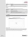
The Control Panel provides a number of run controls and output displays to monitor and control the progress of a
simulation run. The control panel for an example simulation run is shown in the figure below.
JaamSim Control Panel
The panel is divided into three rows, consisting of the menu bar, tool bar, and status bar, which are described in the
following sections.
Menu Bar
File
Clicking on the File entry displays a menu with actions related to saving and loading model input configuration files:
Menu Entry
Description
New
Launches a new, blank model with no objects defined.
Open
Loads a saved configuration from file.
Save
Saves the model under the present input configuration file name.
Save As…
Saves the current model as a new input configuration file.
Print Input Report
Prints the present inputs in a standard file format (.inp).
Exit
Closes all windows and exits JaamSim.
Tools
Clicking on the Tools entry displays a menu allowing the user to bring up each of the windows that make up the
JaamSim graphical user interface:
TLS2013-42
October 23, 2013
5
Menu Entry
Description
Model Builder
Drag and drop creation and placement of simulation objects.
Object Selector
Tree listing of all objects in the present simulation model.
Input Editor
View and edit keyword inputs for the selected simulation object.
Output Viewer
Key output values of the selected object.
Property Viewer
Detailed summary of the internal properties of the selected object.
The Property Viewer is typically used by programmers who are developing and debugging JaamSim applications,
and so its usage is beyond the scope of this manual.
Views
A View is a window showing a graphical 3D representation of the model. The Views entry displays a menu
containing a list of currently defined views of the system, as well as a single action:
Menu Entry
Description
Define new View
Creates a new View object and displays its window.
Options
Clicking on the Options entry in the menu bar generates a menu containing the following entries:
Menu Entry
Description
Show Position
If checked, the status bar displays the current position of the mouse cursor within the active view
window.
Always On Top
If checked, the control panel will always remain on top of other windows.
Tooltip
If checked, tooltips will be displayed as the cursor is moved on top of objects.
Help
Clicking on the Help entry in the menu bar displays a single menu option that shows the software version number and
copyright information.
Tool Bar
The Tool Bar contains controls for manipulating the simulation run and the 3D view for the active display window.
Run Controls
Tool Bar Item
Description
Run/Pause Simulation
Starts, pauses and resumes the simulation run.
Stop Simulation
Stops the simulation run and prepares it for re-starting at time zero.
Pause at:
Entering a value here (in hours of simulated time) pauses the simulation when it reaches that time.
Real Time
If pressed, the simulation speed is held to a constant multiple of wall-clock time.
Real Time Multiplier
The ratio of simulated time to wall-clock time that is used when the Real Time feature is active.
View Controls
TLS2013-42
October 23, 2013
6
Tool Bar Item
Description
Isometric
Transforms the active view window to an isometric representation to give the viewer a sense of depth in
all dimensions.
XY-Plane
Transforms the active view window to a bird's eye view directly above the x-y plane of the simulation.
Status Bar
The Status Bar consists of indicators to illustrate the progress and status of the simulation run:
Status Bar Item
Description
Simulation Time
The number of simulated hours elapsed.
Progress Bar
Percentage of simulated time completed.
Speed Up
The ratio of simulated time to wall-clock time.
Time Remaining
Minutes of wall-clock time remaining until the simulation is completed.
Pos
Location of the mouse cursor in the active view window expressed in { x, y, z } coordinates.
3.2 - View Windows
View windows, shown in the figure below, display a graphical representation of a simulation. Multiple view windows
can be defined depicting different parts of a model. Each view window is an instance of a View object and can be
modified interactively.
View Window with Default Graphical Entities
Moving the Camera
The basic camera movements are zoom, pan, and orbit. The user can zoom the camera by using the mouse wheel
and pan the camera by clicking and dragging the mouse cursor around the view window. Dragging the mouse with
the right button depressed causes the camera to orbit around the current point of interest. These movements are
described in more detail below along with a number of other useful camera manipulations.
TLS2013-42
October 23, 2013
7
Mouse/Keyboard Action
Effect on the Camera
Left Click
Selects Point of Interest. The point on the surface of the object under the pointer becomes the point of
interest. If no object is under the pointer, then the point on the x-y plane is used.
Scroll Wheel
Zooms the camera in or out. The camera is moved towards or away from the point of interest. One click
moves the camera 10% closer to or farther away from the point of interest.
Left Drag
Horizontal pan. The camera is moved horizontally from its present position so that the pointer stays
fixed on the same object in the scene. If no object is under the pointer, then the point on the x-y plane is
used. The point of interest is reset to the pointer position. Movement is restricted to no closer than 1
degree from the horizon to protect the user from an accidental trip to infinity.
Shift + Left Drag
Vertical pan. The camera is moved vertically from its present position so that the pointer stays fixed on
the same object in the scene. If no object is under the pointer, then the point on the x-y plane is used.
The point of interest is reset to the pointer position.
Right Drag
Orbit. The camera orbits left/right and up/down around the point of interest, following the mouse
movement.
Shift + Right Drag
Look around. The camera looks left/right and up/down, following the mouse movement. The point of
interest is unchanged.
Moving and Resizing Objects
Individual objects can be moved around using mouse controls that are analogous to the camera controls. To avoid
moving an object accidentally, it is necessary to press the Control key during any movement. After selecting an object
in the Object Selector or by clicking it in a view window, its position, size, and orientation can be manipulated
interactively by pressing the Control key and dragging the entire object, a corner of the object, or its rotation handle
using the mouse. By default, dragging an object moves it in the x-y plane. An object can be moved in the z-direction
by holding down both the Control and Shift keys and dragging the object up and down. These actions are described
in more detail in the following table.
Mouse/Keyboard Action
Effect on the Object
Left Click
Selects the object. The object under the pointer is selected for input/output viewing and for repositioning, re-sizing, or rotating. The selected object is indicated by a green rectangle that
encompassed the object. Green handles are also provided to allow the object to be re-sized or rotated.
Control + Left Drag
Moves the object horizontally. The selected object is moved in a plane parallel to the x-y plane, following
the pointer.
Shift + Control + Left Drag
Moves the object vertically. The selected object is moved vertically, following the pointer.
Control + Left Drag on a
Handle
Resizes/rotates the object. The selected object is re-sized or rotated using the selected handle.
Moving and Re-shaping Linear Objects
In addition to the standard controls described above, linear objects, such as an Arrow, can be re-shaped by adding
and removing joints and by moving individual joints. The actions for linear objects are described in the following table.
TLS2013-42
October 23, 2013
8
Mouse/Keyboard Action
Effect on the Object
Left Click on the Line
Selects the line. The line under the pointer is selected for input/output viewing and for re-positioning, resizing, or rotating. The selected line is indicated by turning green and green handles appear at each joint
in the line.
Control + Left Drag on the Line Moves the entire line horizontally. The selected line is moved in a plane parallel to the x-y plane,
following the pointer.
Shift + Control + Left Drag on
the Line
Moves the entire line vertically. The selected line is moved vertically, following the pointer.
Control + Left Drag on a
Handle
Moves location of the joint horizontally. The lines on either side of the joint adjust to following the joint.
Shift + Control + Left Drag on a
Moves the location of the joint vertically.
Handle
Alt + Control + Left Click on
the Line
Adds a new joint and Handle to the line.
Shift + Alt + Control + Left
Click on a Handle
Deletes the joint and re-connects the joints on either side of the deleted joint.
Context Menu
Right-clicking in the view window generates a menu listing all objects whose graphical representation lies under the
mouse cursor. Selecting an object here (or in the case that there is only one object underneath the mouse cursor)
generates a submenu with the following entries:
Menu Item
Description
Input Editor
Selects the object and opens its Input Editor window.
Output Viewer
Selects the object and opens its Output Viewer window.
Property Viewer
Selects the object and opens its Property Viewer window.
Duplicate
Creates a copy of the selected object in the current view window.
Delete
Deletes the selected object.
Change Graphics
Opens a dialog box to select a new DisplayModel graphical representation for the selected object.
Add Label
Creates a Text object with its name and RelativeEntity keywords set to the selected object.
Center in View
Selects the object and centers the current View on it.
Default Objects
When a new model is created, a default view window (View-1) is created along with two graphical objects that
appear in this window: XY-Grid and XYZ-Axis. These objects, intended as visual aids for placing new objects, are
regular static graphics (DisplayEntity objects) and so can be deleted by the user. The "Movable" keyword is set to
FALSE for both objects, so that they cannot be moved accidentally and do not respond to mouse clicks.
3.3 - Model Builder
The Model Builder provides palettes of objects that can be dragged and dropped to construct a new model or to
modify an existing one. The figure below shows the Model Builder with the Graphical Objects palette opened, ready
for dragging and dropping.
TLS2013-42
October 23, 2013
9
Model Builder
Once an object has been created by dragging and dropping it from the Model Builder into a view window, its inputs
are entered using the Input Editor.
Some objects do not have any graphics. These objects can still be created by dragging and dropping from the Model
Builder to a view window. Although the new object will be invisible, it will appear Object Selector and its inputs can be
edited in the Input Editor.
When a model is saved, JaamSim generates an input configuration file that contains all of the objects that have been
created along with their input values.
JaamSim includes six built-in palettes of objects:
Simulation Controls
Units
Display Models
Graphics Objects
Probability Distributions
Basic Objects
The first three palettes contain meta-objects that are not intended for creation by the user. They appear in the Object
Selector, but not in the Model Builder. The last three palette contain the standard objects that are needed for most
simulation models. A JaamSim application, such as Ausenco's TLS, will include additional palettes of objects
created specifically for that application.
3.4 - Object Selector
The Object Selector is an index of all the objects that have been created for the present model, including ones that
were created automatically by JaamSim. Objects are grouped according to their palette and type in a tree format that
mirrors the structure of the Model Builder. A specific object can be selected either by clicking its node in the Object
Selector or by clicking it in a view window. The figure below shows the Object selector with the Graphics Objects and
DisplayEntity nodes expanded.
TLS2013-42
October 23, 2013
10
Object Selector
Objects that have been created using the Model Builder can be renamed or deleted using the Object Selector. Once
an object has been selected, it can be renamed by clicking on its entry in the Object Selector or by pressing F2,
similar to the convention in Windows. It can be deleted by pressing the Delete key, or by right-clicking the object in a
view window or the Object Selector and selecting Delete.
3.5 - Input Editor
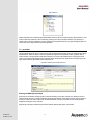
The Input Editor allows the user to modify inputs for objects already defined in the model or to assign inputs to newlydefined objects. When an object is selected, its parameters appear in the Input Editor window, grouped under a
number of tabs. If a keyword has a default value assigned, it is shown in the Default column. Hovering the mouse
cursor over a keyword will display a tooltip containing a brief description of the keyword and an example input. The
figure below shows the Input Editor with the tooltip for Size.
Input Editor with Keyword Tooltip Mouseover
Entering and Editing Keyword Inputs
Keywords are modified by clicking the Value column and entering a new value, including units. Numbers must be
entered without spaces or commas and Boolean keywords must take the value TRUE or FALSE (case sensitive). If
an entry is made in the Value column, it will overwrite the default. If an input is not valid, an error message will be
displayed showing the cause of the error.
Depending on the object, different keyword values will have different data types. These include:
TLS2013-42
October 23, 2013
11
Numbers without units. Specified with or without a decimal point, e.g. { 5 }, { 5.0 }, and { 5. } are equivalent
entries.
Numbers with units. An pre-defined unit must be included, e.g. { 1000 mm }, { 1.0 m }, and { 0.001 km } are
equivalent entries.
Boolean values. Indicated as either TRUE or FALSE (case-sensitive).
Colours. Specified by a colour keyword or by an RGB value, e.g. { pink } and { 255 192 203 } are equivalent
entries.
Strings. The text must be enclosed in single quotes(') if it contains any spaces, e.g. { 'a b c' }. Note that { 'abc'
} and { abc } are equivalent entries.
Objects. For example { View-1 } indicates the view window, View-1, created automatically by JaamSim.
Object outputs. Specified by an object name and an output name, e.g. { Queue-1 QueueLength } is the output
named "QueueLength" for the queue object Queue-1.
Many keywords that expect a number can also accept other types of inputs that return a number, such as a probability
distribution or a time series.
Curly braces are used to delineate distinct entries, as illustrated in the following examples:
Entry Type
Example
A single quantity, with units:
{ 2 m }
A vector quantity, with units:
{ 1.1 0.5 2.3 m }
A set of vectors with units:
{ { 0.0 1.0 0.0 m } { 1.0 1.0 0.0 m } }
The outer set of braces are needed in the input configuration file, but are optional in the Input Editor.
A drop-down menu is available for many types of inputs. For a Boolean input, the user is offered a choice of TRUE or
FALSE. For an object input, the user is offered a list of all the objects of the appropriate type. Similar drop-down
menus are provided for most other types of inputs.
Colour Selection
For readability, it is often preferable to specify a colour input using a colour keyword instead of an RGB value, e.g. {
pink } instead of { 255 192 203 }. A table of standard colour keywords are provided in the last section of this manual.
Alternatively, the Input Editor provides a pop-up menu containing a graphical palette (shown in the figure below) to
aid colour selection. The user can select a colour or adjust the RGB values via slider controls.
Colour Selection Pop-up Window
TLS2013-42
October 23, 2013
12
3.6 - Output Viewer
The Output Viewer displays the pre-programmed outputs that are available for the selected object. Output values are
updated continuously as the simulation progresses. Numerical outputs are displayed in SI units unless a preferred
unit is specified.
The output system provided by JaamSim is the basis for all model graphics and reports. An object can be animated
by connecting a pre-defined Action in its DisplayModel to one of its Outputs.
The figure below shows the outputs provided for a Queue object named "Que".
Output Viewer
TLS2013-42
October 23, 2013
13
4 - Simulation Controls Palette
For each JaamSim model, one Simulation object (named "Simulation") is used to store inputs used to define basic
parameters of the model, such as run duration.
List of objects:
Simulation
4.1 - Simulation
As with other objects, the simulation parameters are changed using the Input Editor. The Simulation object is found in
the Object Selector under:
Simulation Controls ► Simulation ► Simulation.
The simulation parameters can also be defined directly in the Input Configuration File. Unlike other objects, the
Simulation object is automatically created when a new model is started and does not have to be defined by dragging
and dropping from the Model Builder.
Key Inputs:
TLS2013-42
October 23, 2013
Keyword
Description
Duration
Duration of the simulation run in which statistics will be recorded.
Initialization
Length of the initialization period from which the run statistics are discarded before the simulation is run
for the time specified in Duration. Allows the model to reach steady-state before statistics are recorded.
The total length of the simulation run is the sum of Initialization and Duration.
ExitAtStop
If TRUE, JaamSim will close all windows and exit when the simulation run is finished.
SimulationTimeScale
The number of discrete time units in one hour, e.g. a value of 3600 means that the smallest time
increment is one second.
PrintInputReport
If TRUE, an input report is generated once the simulation is loaded. The report can otherwise be
generated from the File menu.
RealTimeFactor
A numerical multiplier that defines how quickly, with respect to wall-clock time, the simulation runs.
RealTime
If TRUE, then the simulation runtime is held constant at a multiple of real time. If FALSE, then the
simulation runs as fast as possible (and may vary) throughout the run.
14
5 - Units Palette
JaamSim performs all internal calculations in SI units (meters, kilograms, seconds, etc.). However, many quantities
employed by simulation users are more conveniently specified in other unit systems. To this end, JaamSim natively
supports a number of commonly used units, shown in table below.
Unit Type
Default Unit
Supported Units
TimeUnit
seconds (s)
min, h, d, w, y, ms, us, ns
DistanceUnit
meters (m)
m, km, nmi, mi, ft, in, mm
SpeedUnit
meters per second (m/s)
m/s, km/h, knots, mph
AccelerationUnit
meters per squared second (m/s²)
ft/s²
MassUnit
kilograms (kg)
tonnes, kt, Mt
MassFlowUnit
kilograms per second (kg/s)
(any mass unit)/(h, d, y)
VolumeUnit
cubic meters (m³)
km³, bbl, mbbl, mmbbl
VolumeFlowUnit
cubic meters per second (m³/s)
(any volume unit)/(h, d, y)
AngleUnit
radians (rad)
degrees
AngularSpeedUnit
radians per second (rad/s)
rad/h, deg/s, deg/h
EnergyUnit
joules (J)
kWh
EnergyDensityUnit
joules per cubic meter (J/m³)
kWh/m³
SpecificEnergyUnit
joules per kilogram (J/kg)
kWh/t
PowerUnit
watts (W)
kW, MW
CostUnit
dollars ($)
CostRateUnit
dollars per second ($/s)
$/h, $/d
LinearDensityUnit
kg/m
t/m, kt/m
DimensionlessUnit
LinearDensityVolumeUnit m³/m
DensityUnit
kg/m³
PressureUnit
Pa
kPa, psi
ViscosityUnit
Pa-s
P, cP
AreaUnit
m²
cm², mm², in²
RateUnit
/s
/h, /d, /w, /y
Units are mandatory for most numerical inputs with the exception of pure numbers or ratios, or in a few cases for
older inputs that have not yet been updated with this requirement. Inputs that are pure numbers are indicated by the
DimensionlessUnit type.
Distinct object types (corresponding to the Unit Types in table below) are defined for different unit types, but all Unit
objects have the same three keywords.
Key Inputs:
TLS2013-42
October 23, 2013
15
Keyword
Description
ConversionFactorToSI
Two numbers that specify the numerator and denominator, respectively, of the multiplicative factor to
convert from the new unit to SI base units.
PreferredUnit
The unit to be used in the Output Viewer for this unit type. If no unit is entered, the Output Viewer
defaults to the SI unit. The value entered for this keyword is shared between all the units for a given unit
type.
Alias
A list of alternate names for the new unit that can be used when specifying quantities using this unit in
other keywords.
5.1 - Defining a New Unit
In addition to the pre-existing unit types defined in JaamSim, the user can specify new units using a Unit object. A
new unit object can be created by right clicking on an existing unit and selecting duplicate. After the unit is renamed
appropriately, its ConversionFactorToSI input can be set to the desired value. For example, to create a new
TimeUnit for "fortnight" (two weeks), the ConversionFactorToSI keyword should be set to { 1209600 1 }. Once this
has been done, keyword values in units of time will subsequently support the Fortnight unit when values are
entered.
5.2 - Setting a Preferred Unit
Model outputs are normally shown in the appropriate SI unit in the Output Viewer. In many cases, it is useful to show
outputs in another unit. For example, it might be better to view a time output in terms of hours instead of seconds (the
SI unit for time). This change can be accomplished by setting the PreferredUnit keyword for a TimeUnit to { h }. Any
TimeUnit can be used for this purpose. The same result would be obtained by using s (seconds), h (hours), d (days),
or any other TimeUnit. Changing the PreferredUnit keyword for one TimeUnit changes this keyword's value for all
TimeUnits.
TLS2013-42
October 23, 2013
16
6 - Display Models Palette
The graphical appearance of a DisplayEntity and its subclasses is determined by its DisplayModel. The two objects
work together to generate an object's display. In general, the DisplayEntity determines what is displayed, while its
DisplayModel determines how it is displayed. A number of different subclasses of DisplayModel are available to
match the various subclasses of DisplayEntity.
For example, the Text object (a subclass of DisplayEntity) and the TextModel (a subclass of DisplayModel) work
together to display text. The text to be displayed is determined by the Text object, while the style of the displayed text
(font, bold, italics, color, etc.) is determined by the TextModel object. In this case, the TextModel plays the same role
as a text style in word processing software. The analyst can ensure that the same text style is used for multiple Text
objects by sharing the same TextModel between all these objects.
The ability to share one DisplayModel between multiple DisplayEntities is an essential feature for the case of
complex 3D content built from thousands or millions of triangles. In this case, a ColladaModel (as subclass of
DisplayModel) stores 3D information that can be shared between multiple DisplayEntities. The 3D content is loaded
and stored only once, even though it is displayed many times in various locations. Even in the case of animated 3D
content, only one ColladaModel is needed to display a different animation state in each location.
A selection of DisplayModels can be found in the "Display Models" folder in the Object Selector. Each of these
subclasses of DisplayModel in intended for a particular subclass of DisplayEntity, as noted below. Only the most
important types of DisplayModel are described in this section.
List of objects:
TextModel
ImageModel
ColladaModel
GraphModel
6.1 - Basic Graphics
All Display Model objects have the same Basic Graphics keywords, described below, for controlling optional
rendering and scaling at different drawing ranges. In addition, several types of Display Models have additional
keywords which govern their appearance. Key inputs for these special examples are included in their respective
sections.
Key Inputs:
Keyword
Description
VisibleViews
A list of views for which this Display Model is shown. If empty, the model appears on all views.
DrawRange
A list of two values for the minimum and maximum distance from the camera this object is visible.
ModelScale
A list of three multiplicative factors by which to scale the model in the x-, y- and z-dimensions
respectively.
6.2 - TextModel
TextModel objects specify the general appearance of text objects (Text, OverlayText, and OverlayClock) in addition
to their optional rendering properties. A TextModel object can therefore be used as a style class, with all text
instances that have the same style sharing the same TextModel. The table below describes the additional inputs for
TextModel objects.
Key Inputs:
TLS2013-42
October 23, 2013
17
Keyword
Description
FontName
The font face to be used for text with this TextModel (selectable via a drop-down menu)
FontColour
The color of the text, defined by a color keyword or RGB values.
FontStyle
Styles (BOLD, ITALIC) to be applied to the font (selectable via a pop-up menu).
DropShadow
If TRUE, a drop shadow is displayed below the text.
DropShadowColour
The colour of the drop shadow, defined by a color keyword or RGB values.
DropShadowOffset
The spacing between the text and its drop shadow, specified in { x, y, z } coordinates.
6.3 - ImageModel
ImageModel objects are used to display custom 2D graphics in a simulation model, such as a picture or a map. Both
DisplayEntity and OverlayImage can accept an ImageModel object as an input. Image file types currently supported
by JaamSim include BMP, GIF, JPG, PCX and PNG files, or a ZIP file containing one of these file types. The table
below describes the additional inputs for ImageModel objects:
Key Inputs:
Keyword
Description
ImageFile
A file path to the image file to be used for this display model. Must be enclosed in single quotes (') if the
path contains spaces.
Transparent
If TRUE, transparency is enabled for supported image types (GIF and PNG).
CompressedTexture
If TRUE, image compression is applied in order to alleviate memory issues with large images.
6.4 - ColladaModel
ColladaModel objects are used to display custom 3D graphics in a simulation model. The COLLADA file format
(.DAE) is an interchange file format used for 3D graphics. Any 3D object such as a DisplayEntity and most of its subclasses can accept a ColladaModel as its DisplayModel.
A number of other 3D formats can be used in addition to Collada. At the present time, JaamSim supports DAE,
OBJ, and JSM formats. The latter JSM format is specific to JaamSim and was introduced to allow 3D objects to be
animated. JSM files can be created using a plug-in for Blender, an open-source 3D graphics program. Animation is
still in the early stages of development at the present time. Please contact us for more information if you wish to use
this feature.
The table below describes the additional inputs for ColladaModel objects:
Key Inputs:
Keyword
Description
ColladaFile
A file path to the DAE, OBJ, or JSM file to be used for this display model. A ZIP file containing a DAE
file and its related texture files can also be used, and is the recommended option for this format. The file
path must be enclosed in single quotes (') if it contains spaces.
Actions
A list of animation Actions and the object Outputs to which they are to be connected, in the format { {
Action1 Output1 } { Action2 Output2 } }. In this example, the actions Action1 and Action2 must be
available for the graphical asset specified by the ColladaFile input. The outputs Output1 and Output2
must be valid outputs for the entity to which this ColladaModel is assigned. Animation is only available
for 3D objects in the JSM format.
The following outputs are provided for ColladaModels:
TLS2013-42
October 23, 2013
18
Outputs:
Output Name
Description
Actions
A list of the actions that are provided in the JSM file.
Vertices
The number of unique vertices that are specified in the 3D model.
Triangles
The number of unique triangles that are specified in the 3D model.
VertexShareRatio
The ratio (number of triangles)/[ (number of vertices)/3 ]. Equal to 1.0 if every vertex is used in only one
triangle.
6.5 - Creating a new DisplayModel
New Display Models can be defined by duplicating an existing example. JaamSim starts with a pre-defined example
of each type of Display Model. Duplicate an example Display Model by right-clicking its entry in the Object Selector
and selecting "Duplicate", then edit its attributes and name as necessary.
TLS2013-42
October 23, 2013
19
7 - Graphics Objects Palette
This section describes the objects found in the Graphics Objects palette in the Model Builder. This palette contains
objects used in the visualization of a simulation model. For advanced features and detailed operating rules on an
object, select it in the Input Editor and hover over a keyword for a tooltip describing the keyword and an example
input.
List of objects:
View
DisplayEntity
Text
Overlay Objects
Arrow
Graph
7.1 - Basic Graphics Keywords
All objects intended for visualization in a model display window in JaamSim have a set of Basic Graphics keywords
used to define their appearance. These are found in the Basic Graphics tab of the Input Editor when the object is
selected.
Key Inputs:
Keyword
Description
Position
The point in the region at which the alignment point of the object is positioned.
Alignment
The point within the object about which its Position keyword is defined, expressed with respect to a unit
box centered about { 0, 0, 0 }.
Size
The size of the object in { x, y, z } coordinates. When two coordinates are given it is assumed that z =
0. When the size is changed, the coordinates of the center are held fixed and the eight corners are
moved.
Orientation
The three Euler angles defining the rotation of the object.
RelativeEntity
An object with respect to which the Position keyword is referenced. If that object is moved, any object
connected by RelativeEntity will also move.
DisplayModel
The graphical representation of the object. Accepts a list of multiple Display Model objects for
compatibility with level of detail and optional rendering.
Active
If TRUE, then the object is active and used in the simulation run.
Show
If TRUE, then the object is shown in the simulation view windows.
Movable
If TRUE, then the object can be positioned by dragging with the mouse. Non-movable objects do not
respond to mouse interactions in the View windows.
ToolTip
If TRUE, then tool tips are displayed when hovering over the object during the simulation run.
7.2 - View
When the Views menu is selected from the menu bar, a list of View objects is displayed. Each View object consists
of an imaginary camera positioned in the world and a window in which to display the image. Clicking one of these
objects will display the View in a new window (or bring the view window into focus if already displayed). The
graphical position of objects is not used by any of the simulation model calculations. All graphics are for display
purposes only.
Key Inputs:
TLS2013-42
October 23, 2013
20
Keyword
Description
ViewCenter
The position in space that the View window is looking at.
ViewPosition
The position in space that the View window is looking from.
WindowSize
The size of the view window, in pixels.
WindowPosition
The position of the view window, in pixels, with respect to the upper-left hand corner of the computer
screen.
TitleBarText
Text to place in the title bar of the view window.
ShowWindow
If TRUE, the view window is displayed on-screen.
7.3 - DisplayEntity
DisplayEntity is a general static graphical object that can be placed in a simulation model for visualization purposes.
For example, a DisplayEntity is used to insert a map overlay in a model visualization. In general, such graphics are
included by creating a DisplayEntity object and setting its DisplayModel keyword value (in the Basic Graphics tab) to
the desired shape (or custom image). This can be done using the Input Editor as with other keyword, or by rightclicking the DisplayEntity in a view window and selecting the Change Graphics menu item.
All JaamSim objects that have graphics are sub-classes of DisplayEntity. There are no special inputs for
DisplayEntity aside from the Basic Graphics inputs.
7.4 - Text
The Text object is used to define static or dynamic text to be displayed in a view window. They are used for general
purposes of labelling and status monitoring. In addition to the Basic Graphics keywords, the table below describes
key inputs for the Text object.
A Text object for a specific graphical entity can be generated automatically by right-clicking the object in a view
window and selecting "Add Label". The Format keyword will be automatically populated with the name of the target
entity and will have its RelativeEntity keyword set so that the label follows the target entity when it is moved.
Key Inputs:
TLS2013-42
October 23, 2013
Keyword
Description
Format
The fixed and variable text to be displayed. If spaces are included, enclose the text in single quotes ('). If
variable text is to be displayed using the OutputName keyword, include the appropriate Java format in
the text, e.g. %s, %.6f, %.6g.
OutputName
The output value chain that returns the variable text to be displayed. If more than one output value is
given, all outputs but the last should point to an entity output to query for the next output. For example, {
Tank-1 Product Name }, returns the name of the product in Tank-1.
Unit
The unit in which to express the output value. Required only for outputs that return a number.
TextHeight
The size of the font as displayed in the view window.
21
7.5 - Overlay Objects
Overlay objects are special versions of other objects that are used for graphical display in a simulation model. Unlike
other display objects, the position of overlay objects is referenced to the corner of a view window, and so the object
does not move when the view is panned or zoomed. These objects are useful for labelling view windows or
displaying the model name and company logos. There are three types of overlay objects, each corresponding to a
different graphical object type. The relationship between each overlay object, its parent object type, and its usage is
summarized below.
Overlay Object
Parent Object
Usage
OverlayImage
DisplayEntity
Static image (Logos, other graphics)
OverlayText
Text
Static of dynamic text (Model name, states, rates)
OverlayClock
Text
Current time in the simulation model.
Each type of overlay object takes the keywords associated with its parent object. For instance, the Format and
TextHeight keywords must be supplied for an OverlayText object. Additionally, instead of the Basic Graphics
keywords common to other display objects, overlay objects have the following keywords:
Key Inputs:
Keyword
Description
ScreenPosition
A list of two numbers specifying the spacing (in pixels) between the left and top corner of the View
window and the object.
AlignRight
If TRUE, the horizontal alignment is referenced to the right side of the view window instead of the left.
AlignBottom
If TRUE, the vertical alignment is referenced to the bottom side of the view window instead of the top.
7.6 - Arrow
An Arrow object consists of a line (possibly multiple line segments) and an arrowhead. It can be used to point out
objects in a view window. In addition to the Basic Graphics keywords, the table below describes keywords used for
this object in particular.
Key Inputs:
Keyword
Description
Points
A list of points (in { x, y, z } coordinates) defining the line segments that make up the arrow. When two
coordinates are given it is assumed that z = 0.
ArrowSize
A set of { x, y, z } numbers that define the size of the arrowhead in those directions at the end of the
connector.
Width
The width of the arrow line segments in pixels.
Colour
The colour of the arrow, defined using a colour keyword or RGB values.
Arrows (and other graphical objects that use the Points keyword) ignore the Position, Alignment and Orientation
keywords, since their placement is defined completely by their Points coordinates.
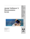
7.7 - Graph
The Graph object is a real-time visual representation of one or more property values, displaying its current value in
the context of its recent history. Property values are accessed for the Graph object by target methods that are
specific to the property of interest.
TLS2013-42
October 23, 2013
22
The figure below shows an example of a graph, with keywords related to formatting its appearance labelled directly
on the graph.
Sample Graph with Formatting Keywords Defined Graphically
Data Keywords:
Keyword
Description
NumberOfPoints
The number of data points to be displayed on the graph. This determines the resolution of the graph.
DataSource
One or more sources of data to be graphed against the primary y-axis.
LineColours
A list of colours for the data series to be displayed. For multiple colours, each colour must be enclosed
in braces as each colour can be itself defined as a list of RGB values.
LineWidths
A list of widths (in pixels) for the data series to be displayed.
SecondaryDataSource
One or more sources of data to be graphed against the secondary y-axis.
SecondaryLineColours
A list of colours for the data series to be displayed. For multiple colours, each colour must be enclosed
in braces as each colour can be itself defined as a list of RGB values.
SecondaryLineWidths
A list of widths (in pixels) for the data series to be displayed.
X-Axis Keywords:
Keyword
Description
XAxisUnit
The time unit to be used for the x-axis.
StartTime
The amount of time (in hours) to display data before the present time.
EndTime
The amount of time (in hours) to display data after the present time.
TimeInterval
The number of hours between time labels on the x-axis. Time labels are shown starting from StartTime.
XAxisLabelFormat
The Java format to be used for the tick mark values on the x-axis.
XLines
A list of time values between StartTime and EndTime where vertical gridlines are inserted.
XLinesColor
Colour of the vertical gridlines (or a list corresponding to the colour of each gridline defined in XLines),
defined using a colour name or RGB values.
Y-Axis Keywords:
TLS2013-42
October 23, 2013
23
Keyword
Description
YAxisTitle
Title text of the y-axis, rotated by 90 degrees counter-clockwise.
YAxisUnit
The unit to be used for the primary y-axis.
YAxisStart
The minimum value for the y-axis (in units of the target method).
YAxisEnd
The maximum value for the y-axis.
YAxisInterval
The interval between y-axis labels.
YAxisLabelFormat
The Java format to be used for the tick mark values on the y-axis.
YLines
A list of values at which to insert horizontal gridlines.
YLinesColor
Color of the horizontal gridlines, defined using a color name or RGB values.
Secondary Y-Axis Keywords:
Keyword
Description
SecondaryYAxisTitle
Title text of the secondary y-axis, rotated by 90 degrees clockwise.
SecondaryYAxisUnit
The unit to be used for the secondary y-axis.
SecondaryYAxisStart
The minimum value for the secondary y-axis.
SecondaryYAxisEnd
The maximum value for the secondary y-axis.
SecondaryYAxisInterval
The interval between secondary y-axis labels.
SecondaryYAxisLabelFormat The Java format to be used for the tick mark values on the secondary y-axis.
Layout Keywords:
Keyword
Description
Title
Text for the graph title, enclosed in single quotes (') if it contains spaces.
TitleTextHeight
Text height for the graph title.
YAxisTitleTextHeight
Text height for the y-axis title.
LabelTextHeight
The text height for both x- and y-axis labels.
TitleGap
The gap between the graph title and the top of the graph.
XAxisLabelGap
The gap between the x-axis and its labels, as shown in the sample figure above.
YAxisTitleGap
The gap between the y-axis labels and the y-axis title, as shown in the sample figure.
YAxisLabelGap
The gap between the y-axis and its labels, as shown in the sample figure.
TopMargin
BottomMargin
LeftMargin
Size of the gaps between the respective edges of the outer pane and the graph, as shown in the sample
figure.
RightMargin
TLS2013-42
October 23, 2013
LabelFontName
The font name for all labels.
TitleColor
Text color of the graph title, defined by a color keyword or RGB values.
LabelFontColor
The colour of both x- and y-axis labels, defined using a color name or RGB values.
GraphColor
The color of the graph background, defined by a color keyword or RGB values.
BackgroundColor
The color of the outer pane background.
BorderColor
The color of the graph border.
24
8 - Probability Distributions Palette
The probability distributions palette provides a standard selection of theoretical distributions as well as user-defined
distributions.
8.1 - Theoretical Probability Distributions
The following set of standard probability distributions are available. The distributions were coded using algorithms
adapted from "Simulation Modeling & Analysis", 4th Edition, by Averill M. Law. The standard Java random number
generator is used (a linear congruential algorithm).
Distribution Name
Description
UniformDistribution
Generates samples with a constant probability between a minimum and maximum value.
TriangularDistribution
Generates samples from a triangular distribution between a minimum and maximum value. The
distribution peaks at its mode.
NormalDistribution
Generates samples from a normal distribution.
ExponentialDistribution
Generates samples from a negative exponential probability distribution.
ErlangDistribution
Generates samples from an Erlang probability distribution.
GammaDistribution
Generates samples from a Gamma probability distribution.
WeibullDistribution
Generates samples from a Weibull probability distribution.
LogNormalDistribution
Generates samples from a Log-Normal probability distribution.
LogLogisticsDistribution
Generates samples from a Log-Logistics probability distribution.
8.2 - User-Defined Probability Distributions
Users can define a distribution point by point, if required. A user-defined distribution can be either a continuously
varying value or one of a discrete set of values.
Distribution Name
Description
ContinuousDistribution
Generates samples over a continuous range of values.
DiscreteDistribution
Generates samples from a discrete set of values.
8.3 - Keywords for Probability Distributions
Each of the distributions uses the following standard keywords in addition to the ones that are specific to an
individual distribution.
Key Inputs:
Keyword
Description
UnitType
The unit type for the value returned by the distribtion, e.g. { TimeUnit }. To keep the units consistent for
other inputs, this input must be set first.
RandomSeed
The random seed to be used by the Java random number generator.
MinValue
The minimum value that can be returned by the distribution. A value less than the minimum is rejected
and re-sampled from the distribution.
MaxValue
The maximum value that can be returned by the distribution. A value greater than the maximum is
rejected and re-sampled from the distribution.
A number of outputs are standard to all distributions.
Outputs:
TLS2013-42
October 23, 2013
25
Output Name
Description
CalculatedMean
The mean value for the distribution calculated directly from the inputs. Ignores the values entered
for the MinValue and MaxValue keywords.
CalculatedStandardDeviation The standard deviation for the distribution calculated directly from the inputs. Ignores the values
entered for the MinValue and MaxValue keywords.
NumberOfSamples
The total number of samples returned by the distribution.
SampleMin
The minimum of the samples returned by the distribution.
SampleMax
The maximum of the samples returned by the distribution.
SampleMean
The average of the samples returned by the distribution.
SampleStandardDeviation
The standard deviation of the samples returned by the distribution.
8.4 - Distributions that Return an Object
Two distributions are available that return an object instead of a number.
TLS2013-42
October 23, 2013
Distribution Name
Description
RandomSelector
Randomly selects an object from a list of objects and probabilities.
EntitlementSelector
Selects an object from a list of objects and probabilities based on an entitlement algorithm. The object
returned is the one that minimizes the difference between the actual number returned for that object and
the expected number to be returned based on the probabilities.
26
9 - Basic Objects Palette
JaamSim includes a palette of basic objects that are commonly used in all simulation applications. These are
objects that do not necessarily represent a physical entity in the world, but are used in the definitions of certain
application-specific objects. In general, the use of these basic objects will be directed by the object documentation in
the manuals of specific modules.
List of objects:
Queue
TimeSeries
9.1 - Queue
A Queue object defines a location for simulation entities to wait for processing by other simulation entities. For
instance, the Ausenco TLS object PortManager (responsible for mediating the interaction between objects in a port)
requires the definition of a series of Queue objects, which represents a succession of stages at which incoming
ships may have to wait (due to other ships, inclement weather, or other issues).
Key Inputs:
Keyword
Description
Spacing
The amount of graphical space between objects in the queue.
MaxPerLine
Maximum number of objects in each row of the queue.
PrintReport
If TRUE, a queue report file (QUE file) is output summarizing the contents of the queue every time an
object is added or removed.
Outputs:
Output Name
Description
QueueLength
The present number of objects in the queue.
NumberAdded
The total number of objects that have been added to the queue.
NumberRemoved
The total number of objects that have been removed from the queue.
QueueLengthAverage
The average number of objects in the queue.
QueueLengthStandardDeviation The standard deviation of the number of objects in the queue.
QueueLengthMinimum
The fewest number of objects in the queue.
QueueLengthMaximum
The largest number of objects in the queue.
QueueLengthDistribution
A list of decimal values summing to 1.0. The first entry is the fraction of time that the queue is
empty. The second entry is the fraction of time that the queue contains one object, and so on.
The number of entries is equal to the maximum queue length plus one.
9.2 - TimeSeries
An input value that changes over the course of a simulation can be modelled using a TimeSeries object. For
example, the Ausenco TLS object RouteSegment can accept a TransitTimeSeries input, which will vary the transit
time for a ship depending on the simulation time.
TLS2013-42
October 23, 2013
27
Keyword
Description
UnitType
One of the pre-defined unit types within JaamSim. The list of valid UnitTypes can be found in the Object
Selector under Units.
Value
A series of timestamps, along with the associated value for the TimeSeries at the given time. Note: the
UnitType and must be specified before the Value keyword to ensure that the inputs pass validation.
CycleTime
When the time series will repeat from the start. By default, the TimeSeries object will not cycle.
The format for timestamps follows the ISO 8601 standard, and can take one of the following three forms:
YYYY-MM-DD (e.g. 2013-08-25 for August 25, 2013)
YYYY-MM-DDTHH:mm:SS (e.g. 2013-08-25T04:25:00 for 4:25 AM on August 25, 2013)
'YYYY-MM-DD HH:mm:SS' (e.g. '2013-08-25 04:25:00' for 4:25 AM on August 25, 2013)
The first timestamp must occur on January 1, 00:00. The year in TimeSeries Value lists does not need to match the
Simulation StartDate keyword value; the model assumes that both the timestamps and the simulation begin at the
same time. When the simulation reaches the next timestamp of the TimeSeries object, the associated value will be
updated in the model. If the simulation time is greater than the CycleTime, the TimeSeries will repeat from the
beginning of the Value list.
Example: Repeated TimeSeries values
Keyword
Value
UnitType
SpeedUnit
Value
{ { 2014-01-01T00:00:00 0.00 km/h } { 2014-01-03T00:00:00 0.76 km/h } {
2014-01-11T00:00:00 0.24 km/h } }
CycleTime
14 d
In this example, if the simulation started on 2014-01-01, it would take on the new values on January 3 (0.76 km/h) and
then January 11 (0.24 km/h). On 2014-01-15, the first value of the list would be read again and the returned value
from the TimeSeries would be 0. The TimeSeries would take on new values on January 17 and 25, and this 14-day
cycle would repeat until the end of the simulation run.
TLS2013-42
October 23, 2013
28
10 - Advanced Topics
JaamSim has been designed such that simple simulation models can be realized using the Graphical User Interface
alone. However, some specialized functions will require direct editing of the model input configuration file (.cfg file).
The .cfg file is in plain text and can be created using a text editor. We recommend the use of Notepad++, an opensource editor available for download at http://notepad-plus-plus.org.
This section discusses the structure of the input configuration (.cfg) file as well as some examples that require
editing the .cfg file outside of the GUI.
List of topics and objects:
Manipulating CFG Files
Group
ScriptEntity
VideoRecorder
10.1 - Manipulating CFG Files
Basic Structure
A JaamSim input configuration file consists of a series of lines, akin to a scripting language. Each line consists of a
combination of object names, keywords, and values contained within braces. One or more spaces are used to
separate these elements. Braces are also used to denote sets of arguments within the outer braces required for
arguments in general. Blank lines and extra whitespace are ignored by JaamSim.
Comments beginning with a double quote can be used to document the input files. There is no need to use a double
quote mark to end the comment, since JaamSim automatically recognizes the end of a comment with the end of the
line. If a comment extends for several lines, each line must start with a double quote.
Object Definitions
In JaamSim, an object is initialized by a Define statement. The statement contains Define followed by the object
type, and the object name enclosed by braces. Multiple objects can be defined at the same time, provided that they
are of the same type. For instance, the following two lines from an example input configuration file define,
respectively, an Arrow object, and three Arrow objects.
Define Arrow { SingleArrow }
Define Arrow { Arrow1 Arrow2 Arrow3 }
JaamSim ignores extraneous whitespace, allowing the object definition to span multiple lines provided that all
objects are surrounded by braces. Object instances can only be referenced after they have been defined.
Object Inputs
Once an object is defined, its keyword values can be set using a command of the following form:
<object name> <keyword> { <value1> <value2> … }
where value1, value2, … is the list of values for the keyword separated by one or more spaces. For instance, the
following line sets the colour of the Arrow1 object to be black:
Arrow1 Colour { 'black' }
Listings of object types and their parameter keywords can be found elsewhere in this document as well as in
manuals accompanying JaamSim application modules.
Multiple parameters for an object can be set by in one line containing the object name followed by keyword and value
pairs.
TLS2013-42
October 23, 2013
29
Arrow1 Colour { 'black' } Width { 2 }
In either case, the object name must match a name previously listed by the user in a Define statement.
Include Statements
The user can store input data in multiple files and then refer to these files in an input configuration file using Include
statements. These statements refer to other input configuration files by filename and path, surrounded by single
quotes:
Include { '..\Base File\InputFile.cfg' }
Include statements are particularly useful in studies where the analyst wishes to vary only a few inputs across many
simulation runs. Using Include statements, the analyst can create a base case configuration file and then use Include
statements to create simple incremental configuration files for the additional runs:
Include
{ '..\Base File\Basecase.cfg' }
Arrow1 Width { 2.0 }
This example includes the contents of Basecase.cfg and, modifies the already-defined object Arrow1 keyword
Width value to 2.0. Note that the changes from the base case configuration must appear after the Include
statement. These simple configuration files are useful because it is easy to tell exactly how the configuration differs
from the base case configuration.
10.2 - Group
Group objects bundle multiple objects together to simplify inputs. Instead of referring to a long list of objects, a single
group is used instead. The group may be used to set the value for the keyword for all members instead of setting the
value for each member of the group. Certain keywords also accept Group objects as values.
Key Inputs:
Keyword
Description
List
A list of names of the objects included in the list, enclosed by braces.
AppendList
Used to add additional object into a previously-defined group. Added objects will inherit all keywords set
for the group if GroupType is defined.
GroupType
Specifies the object type for the group. Set the GroupType if objects are to be added with AppendList.
Example
The following .cfg file inputs demonstrate creating a list of Arrow objects, after which additional Arrow objects can
be appended to the list, and their colors can be changed together by a single input.
Define
Define
ArrowList
ArrowList
ArrowList
Arrow
Group
List
GroupType
Color
{
{
{
{
{
Arrow1 Arrow2 Arrow3 }
ArrowList }
Arrow1 Arrow2 Arrow3 }
Arrow }
'black' }
By using the AppendList keyword, a newly defined object can take all the previous keyword values set for the
group -- in this case, the arrow colour:
Define
Arrow
{ Arrow4 }
ArrowList AppendList { Arrow4 }
TLS2013-42
October 23, 2013
30
10.3 - ScriptEntity
The ScriptEntity object takes only one keyword, which is the path to a script (.scr) file.
Key Inputs:
Keyword
Description
Script
Name of the file containing the scripting instructions to be loaded.
The script file contains sets of model configuration inputs preceded by the Time keyword (belonging to the
ScriptEntity object). Originally developed for video capture, a script can be used to change window views, to create
automatic zooming and panning, and to turn on and off video capture during a run. Furthermore, keywords defined in
the script file can be used to modify simulation and object parameters initially defined in the input configuration file.
Key Inputs for .scr File:
Keyword
Description
Time
The simulated time at which the subsequent inputs are executed.
Example
The following inputs can be entered into a .scr file and then referenced by a ScriptEntity object in order to slow
down the model at a given point in the simulation run:
ScriptEntity1 Time
{ 24.0 h }
Simulation
RealTime
{ TRUE }
Simulation
RealTimeFactor { 1200 }
ScriptEntity1 Time
Simulation
RealTime
{ 30.0 h }
{ FALSE }
10.4 - VideoRecorder
JaamSim includes functionality to capture still images or videos of simulation models via the VideoRecorder object.
The length and playback speed of the video is governed by three keywords:
CaptureStartTime is the simulated time at which video capture begins;
CaptureFrames is the number of frames to capture;
CaptureInterval is the simulated time elapsed between frames.
The video recorder output frame rate is fixed at 30 frames per second.
The video recorder naturally composites the selected views (from CaptureViews) onto a surface with dimensions
specified in CaptureArea, with windows borders not rendered. The example inputs below illustrate the capture of a
20-second long video (in 1080p resolution) spanning 600 hours of simulated time:
Define VideoRecorder
VideoRecorder1
VideoRecorder1
VideoRecorder1
VideoRecorder1
VideoRecorder1
VideoRecorder1
VideoRecorder1
VideoRecorder1
{ VideoRecorder1 }
VideoCapture
CaptureInterval
CaptureStartTime
CaptureFrames
CaptureArea
SaveVideo
CaptureViews
VideoBackgroundColour
{
{
{
{
{
{
{
{
TRUE }
1 h }
0 h }
600 }
1920 1080 }
TRUE }
Overview }
skyblue }
Key Inputs:
TLS2013-42
October 23, 2013
31
TLS2013-42
October 23, 2013
Keyword
Description
CaptureStartTime
The simulated time at which video capture begins.
VideoBackgroundColor
The background colour for parts of the video frame not covered by a view window.
CaptureFrames
The number of frames to capture.
CaptureInterval
The amount of simulated time elapsed between captured frames.
SaveImages
If TRUE, individual screen captures are made for each frame and output to image files.
SaveVideo
If TRUE, video capture is enabled and an AVI file is output by the video recorder.
CaptureArea
The size of the rendered image or video in pixels.
CaptureViews
A list of views to include in the video or image.
VideoName
The name of the video output file.
32
11 - Colour Name Index with RGB Values
Colour Name
TLS2013-42
October 23, 2013
R
G
B
R
G
B
lavenderblush
Colour
255
240
245
Colour Name
chocolate
Colour
210
105
30
pink
255
192
203
rawsienna
199
97
20
lightpink
255
182
193
sienna
160
82
45
palevioletred
219
112
147
brown
138
54
15
hotpink
255
105
180
lightsalmon
255
160
122
deeppink
255
20
147
darksalmon
233
150
122
violetred
208
32
144
salmon
250
128
114
mediumvioletred
199
21
133
lightcoral
240
128
128
raspberry
135
38
87
coral
255
114
86
thistle
216
191
216
tomato
255
99
71
plum
221
160
221
orangered
255
69
0
orchid
218
112
214
red
255
0
0
violet
238
130
238
crimson
220
20
60
magenta
255
0
255
firebrick
178
34
34
purple
128
0
128
indianred
176
23
31
mediumorchid
186
85
211
burntumber
138
51
36
darkorchid
153
50
204
maroon
128
0
0
darkviolet
148
0
211
sepia
94
38
18
blueviolet
138
43
226
white
255
255
255
indigo
75
0
130
gray99
252
252
252
mediumpurple
147
112
219
gray98
250
250
250
lightslateblue
132
112
255
gray97
247
247
247
mediumslateblue
123
104
238
gray96
245
245
245
slateblue
106
90
205
gray95
242
242
242
darkslateblue
72
61
139
gray94
240
240
240
ghostwhite
248
248
255
gray93
237
237
237
lavender
230
230
250
gray92
235
235
235
blue
0
0
255
gray91
232
232
232
darkblue
0
0
139
gray90
229
229
229
navy
0
0
128
gray89
227
227
227
midnightblue
25
25
112
gray88
224
224
224
cobalt
61
89
171
gray87
222
222
222
royalblue
65
105
225
gray86
219
219
219
cornflowerblue
100
149
237
gray85
217
217
217
lightsteelblue
176
196
222
gray84
214
214
214
lightslategray
119
136
153
gray83
212
212
212
slategray
112
128
144
gray82
209
209
209
dodgerblue
30
144
255
gray81
207
207
207
33
Colour Name
R
G
B
R
G
B
aliceblue
240
248
255
gray80
204
204
204
powderblue
176
224
lightblue
173
216
230
gray79
201
201
201
230
gray78
199
199
199
lightskyblue
135
skyblue
135
206
250
gray77
196
196
196
206
235
gray76
194
194
194
deepskyblue
0
191
255
gray75
191
191
191
peacock
51
161
201
gray74
189
189
189
steelblue
70
130
180
gray73
186
186
186
Colour Name
Colour
darkturquoise
0
206
209
gray72
184
184
184
cadetblue
95
158
160
gray71
181
181
181
azure
240
255
255
gray70
179
179
179
lightcyan
224
255
255
gray69
176
176
176
paleturquoise
187
255
255
gray68
173
173
173
cyan
0
255
255
gray67
171
171
171
turquoise
64
224
208
gray66
168
168
168
mediumturquoise
72
209
204
gray65
166
166
166
lightseagreen
32
178
170
gray64
163
163
163
manganeseblue
3
168
158
gray63
161
161
161
teal
0
128
128
gray62
158
158
158
darkslategray
47
79
79
gray61
156
156
156
turquoiseblue
TLS2013-42
October 23, 2013
Colour
0
199
140
gray60
153
153
153
aquamarine
127
255
212
gray59
150
150
150
mintcream
245
255
250
gray58
148
148
148
mint
189
252
201
gray57
145
145
145
seagreen
84
255
159
gray56
143
143
143
mediumspringgreen
0
250
154
gray55
140
140
140
springgreen
0
255
127
gray54
138
138
138
emeraldgreen
0
201
87
gray53
135
135
135
mediumseagreen
60
179
113
gray52
133
133
133
cobaltgreen
61
145
64
gray51
130
130
130
darkseagreen
143
188
143
gray50
127
127
127
honeydew
240
255
240
gray49
125
125
125
palegreen
152
251
152
gray48
122
122
122
lawngreen
124
252
0
gray47
120
120
120
greenyellow
173
255
47
gray46
117
117
117
limegreen
50
205
50
gray45
115
115
115
forestgreen
34
139
34
gray44
112
112
112
sapgreen
48
128
20
gray43
110
110
110
green
0
128
0
gray42
107
107
107
darkgreen
0
100
0
gray41
105
105
105
34
Colour Name
TLS2013-42
October 23, 2013
Colour
R
G
B
Colour Name
darkolivegreen
85
107
47
olivedrab
107
142
olive
128
128
ivory
255
lightyellow
255
lightgoldenrodyellow
R
G
B
gray40
102
102
102
35
gray39
99
99
99
0
gray38
97
97
97
255
240
gray37
94
94
94
255
224
gray36
92
92
92
250
250
210
gray35
89
89
89
cornsilk
255
248
220
gray34
87
87
87
lemonchiffon
255
250
205
gray33
84
84
84
beige
245
245
220
gray32
82
82
82
yellow
255
255
0
gray31
79
79
79
khaki
240
230
140
gray30
77
77
77
lightgoldenrod
255
236
139
gray29
74
74
74
palegoldenrod
238
232
170
gray28
71
71
71
darkkhaki
189
183
107
gray27
69
69
69
banana
227
207
87
gray26
66
66
66
gold
255
215
0
gray25
64
64
64
goldenrod
218
165
32
gray24
61
61
61
darkgoldenrod
184
134
11
gray23
59
59
59
brick
156
102
31
gray22
56
56
56
floralwhite
255
250
240
gray21
54
54
54
seashell
255
245
238
gray20
51
51
51
oldlace
253
245
230
gray19
48
48
48
linen
250
240
230
gray18
46
46
46
antiquewhite
250
235
215
gray17
43
43
43
papayawhip
255
239
213
gray16
41
41
41
blanchedalmond
255
235
205
gray15
38
38
38
eggshell
252
230
201
gray14
36
36
36
bisque
255
228
196
gray13
33
33
33
moccasin
255
228
181
gray12
31
31
31
navajowhite
255
222
173
gray11
28
28
28
wheat
245
222
179
gray10
26
26
26
peachpuff
255
218
185
gray9
23
23
23
tan
210
180
140
gray8
20
20
20
burlywood
222
184
135
gray7
18
18
18
melon
227
168
105
gray6
15
15
15
sandybrown
244
164
96
gray5
13
13
13
cadmiumyellow
255
153
18
gray4
10
10
10
carrot
237
145
33
gray3
8
8
8
orange
255
128
0
gray2
5
5
5
flesh
255
125
64
gray1
3
3
3
cadmiumorange
255
97
3
black
0
0
0
35
Colour