1
W
M.T
O
No. CP–SS–1814E
W
Y.C
0
T
.
0
OM
W.1
WW .100Y.C M.TW
O
W
W
WW .100Y.C M.TW
T
.
M
WW 00Y.CO .TW
.CO .TW
Y
W
0
0
M
.1
W.1 Y.COM W
WW 00Y.CO .TW
W
W
W
.T
00
W.1 Y.COM W
W.1 Y.COM W
W
W
W
.T
W
00
W
M.T
.100
W.1 Y.COM W
M.T
O
W
O
W
C
.
.C
W
WW .100Y
.TW
M.T
.100
.TW
00Y
M
O
1
W
M
.
O
W
C
.
O
W
W
W
Y
.C
W
WW .100Y.C M.TW
M.T
.100
.TW
00Y
O
1
W
M
.
O
W
C
W
.CO .TW
WW .100Y.
.TW
WW .100Y.C M.TW
M
00Y
O
1
W
M
.
O
W
CO
WW .100Y.C M.TW
WW 00Y.■
W
WW .100Y.C M.TW
T
.
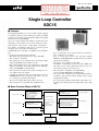
Features
O
W
M
.1
W
.CO .TW
.CODigitroniK
Ycompact
WW .100Y.C M.TW
WW 00YThe
W SDC15 isWa W
0
0
48
x
48mm
digital
T
.
1
M
.
WW 00Y.CO .TW
W.1 Y.COM featuring
.COand .PID
WW 00inputs
groupW
multi-range
W
Y
W
W
T
WW .100controller
T
.1"Rationaloop
W.1 Y.COM W
M. using new algorithms
OM PID
W
control
system
O
W
W
C
.
W
C
W
W
.T
W
00
0Y
W
0Y.
WW .10(Ra-Pid)"
and
M.T
W.1 Y.COM W
M.T"Just-FiTTER". WW.10
O
O
W
W
C
.
C control
Y
W
outputs (thisW
number of points
Y.two
.TW
WW .1Up
M.T
.100
.TW
100 mayOvary
00to
M
.
O
W
M
W
C
.
O
on the model) can be used,
which Y
W depending
W
.Cselect- .TW
WW .100Y
0 are
Y.C the relay
WWpulse,.10and
WW able
M.T
.TW
00from
M
contact,
voltage
current.
O
1
W
M
.
O
W
O
W
.C
WW .100Y.C M.TW
Y.C of mounting
WW
are provided,
00Y panelM.TW
WW Two
.TW methods
1
00kinds
.
1
M
.
O and socket mounting type.
WW 00Y.CO .TW
W
mountingY.type
WW 00Y.CO .TW
C
W
W
W
W
W Additionally,
M
.1
.T
00
.1 CE markOM
OMcontroller is compliantWtoWthe
WW 00Y.CO .TW
W.1 Y.Cthis
C
.
W
Y
W
W
W
0
W
.T• Up to eight pointsW
can
0
W ing. .100
M for the parameter
.1 be registered
M.T
W.1 Y.COM keys,
.CO .TW
Owith
W
W
Y
W
C
ensuring
easy
operation.
W
.
•
Compact
body
a
depth
of
60
mm.
0
W
W
W
Y
W
.T
W
M
.10
.100
M.Tpanel is also only 2W
.100 of theO
OM • Use of "mode" W
keyWensuresY.easy
RUN/
W
CO operation,
The
mask
front
mm
thick.
W
C
.
C
W
.
0
Y
W
TW and EVW
.
W
0
0
Y
W
T
.
1
0
0
W• The accuracy
T
M
.
.
READY,
AUTO/MANUAL,
and
SP
selections,
1
0
is ±0.5%FS.
M
M
.1
W.
WW 00Y.CO .TW
.CO relay
W
CObe changed
W
Y
W
WW
latch
cancellation.
W
• The
input 0type
among
the
thermocouple
0
Y.can
W
T
.
0
0
W
T
M
.1
Ware
M. and linear group. WW.1
.1 RTD group,
OM
.CO .TW
O
•
Up
to
three
event
outputs
provided.
W
W
C
input
group,
.
Y
C
W
.
0
Y
W
W
W
0
0
Y
W
T
0
M DEV, and
.1 such O
.T
00
In .addition to temperatureW
events,
•W
The control
can
the
W.1ON/ Y.COM
.C as PV,.T
OMbe selected from any of
W
W.1 method
W
Y
W
C
W
.
0
W
W
W "Rationaloop
0 burnout,
0
Y control using
W PID (RaT events, such as CT.1heater
SP,
status
over-cur.
OFF
PID
0
0
W control,
T
M
.
1
0
M
.
O
1
W
O and loop diagnosis W
W
OM
W.
W
Y.C
Pid) +W
W can also.1be
W
00set.
Y.Cand self-tuning.
WW .100Y.C rent,
TW
.
0
W Just-FiTTER",
T
M.T
.
0
M
O
1
W
M
.
•
The
controller
is
compliant
to
the
CE
marking
O
• The heat and
cool
control
can
be
achieved
using
two
conW
.C
W
.CO .TW
WW and.1EN61326).
.TW
00Y
WW .100Y.C(safety
TW
.standards
WW and.1event
EN61010-1
M
trol outputs
00Y outputs.
M
O
W
M
O
W
.C makes
O
W
Use of personal
• 18 kinds
of W
operations,
(SP) value selection,
.TWit
W
00Y unit) M
Y.Csuch as .set
WW .100Y• .C
TW computerWloader (optional
.
1
0
WW
T
.
0
M
O
1
W
M
.
O
W
C
possible
to
easily
perform
various
settings,
such
as
setup
RUN/READY
and
can
O latch cancellation, etc.W
W
.C
Y.C
WW .100Y.
WWselection,
.TW
W
0
Y
W
T
.
0
0
W
T
M
.
1
0 switchMinputs.
and
parameter
setting.
M
.
be set using two external
O
1
W
.
O
W
O
W
W
Y.C to easY.Cof personal
WWmakes.1it00possible
• 0Use
Y.C
TWcomputer loader
• The process
variable 0
(PV)
value can.T
beWcorrected. WW
.
0
0
WW
M.T
1
M
.
O
1
W
M
.
O
W
C
W 3-wireYRS-485
single unit0to
• The controllerW
uses
.C the.Tdata
Y.up to eight.TW
W logging from
.CO communications.
WW
0Yachieve
WW .10ily
10
W
M
.
.TW
00
M
units.
1
W
M
.
O
W
.CO .TW
O
W
W
C
.
Y
W
C
W
.
0
Y
W
W
0
W
.T
W
.TW
00Y of M
.100
W.1 Y.COM W
.1Block
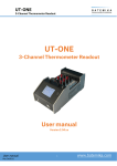
■ Basic Function
SDC15
OM
W
O
W
W
C
.
W
C
W
Y
W
.T
00
W
WW .100Y.
.TW
M.T
.100
W.1 Y.COM W
Mselections
O
W
O
W
W
C
• 11 kinds of thermocouple
•
Relay
contact
.
.Cof ranges) .TW
W
00 (2)
Ykinds
WW .100Y• Voltage pulseMoutput
.TW
(For SSR drive)
WW 2 kinds
M.T
.1outputs
0of0(19RTD
Control
(MV)
selections M
O
1
W
.
• CurrentO
output
W
C
.
O
W
Wkinds of(14DCkinds
of ranges)
W
Y
.C
Y.Coutputs are combined.
W
voltage/current
input
WW .100Above
.TW
WW 6selections
Process variable (PV) input
M.T
.100
.TW
00Y
M
O
1
W
M
.
O
W
C
• Current
value correction
W (PV)
.CO .TW Control operation
WW .100Y.
(PV) value
.T
WW .100Y.C M.TW
0Yfilter
WW•• Current
Current (PV)
ratio
0value
OM
1
W
M
.
O
• PV upper limit,
lower limit, upper/lower limit
W
C
.
O
W
W
C
Y
W
upper/lower limit
.
0Y.upper limit, lower
WW .1•0Deviation
TW
.limit,
WW .100Y.C M.TW• Any of ON/OFF control,
.100
M
OM
• SP upper limit, lower
limit, upper/lower limit
W
O
W
C
.
O
W
W
C
.
Event
outputs
(3)
Y
W
self-tuning,
and
PID
control
C
• MV upper
W limit
.
Ylimit, lower limit, upper/lower
W
Wselected.
W
of selections
00burnout/Over-current
0Y
W• SetW(SP) value,.14 0kinds
M
.100
M.T
.• 1Heater
W
M.T • isDirect/Reverse
O
• RUN/READY
selection
W
CO
External switch inputs (2)
.
O
W
W
action
C
•
EV
functions,
such
as
loop
diagnosis
.
Y
W
C
W
.
0
Y
W
W
• Latch cancellation, etc., 18
W
0
Ykinds
W
W
• Control
allocated.
M.T
.100output can beO
W.1 Y.COM
M.T• Heat/Cool operation
.100
W
O
W
W
C
.
W
C
W
Y
W
W
W
Y.
W
WCurrent
.100
M.T
.100
transformer
W
.100inputs (2) OM.T
O
W
W
W
C
W
WW .100Y.
.TW
WW .100Y.C M.TW
M
O
W
O
W
Y.C
WW 00Y.C
WW
• RS-485
(3-wire)
• Personal computer
Communication input/output
W
.TW
100 loader OM.T Loader communication
.
1
M
.
W
O
W
WW .100Y.C
WW .100Y.C MPower
.TW
supply
W
O 85 to 264Vac,
W
W
WW
WW .100Y.C M
21.6.to
T26.4Vac,
O 21.6 to 52.8Vdc
W
WW .100Y.C M.TW
O
W
WW .100Y.C
W
1
WW
Single Loop Controller
SDC15
<
<
W
M.T
O
.C
W
00Y
1
M.T
.
O
W
C
■ Specifications
WW .100Y.
.TW
M
O
W
PV input
Input type
Thermocouple, RTD, DC current, DC
voltage (Selected by model. See Table 1.)
WW .100Y.C M.TW
.TW
Sampling time
0.5s
M
WW 00Y.CO .TW
.CO
Process variable (PV) -1999
to +9999 orW
-199.9 to +999.9
Y
W
0
T
.
0
correction
W.1 Y.COM W
OM
W.1 Thermocouple
W(under
C
.
W
W
Input bias
current
input:
0.2µA
or
less
Y
W
00 conditions)
0 input: M.T
W
M.T
.1standard
.10RTD
Approx. 1mA (flowed
from A-terminal)
O
W
O
W
C
.
Y or less .TW
Y.C input: .TW 0 - 1V range:
WW .1001µA
WW .1DC
00voltage
M
.TW
M
0 - 5V, 1 - 5V range:
3.5µA orO
less
W
M
O
W
.orCless
O
W
C
.
Y
W
0
10V
range:
7µA
C
W
.
0
Y
W
.TW
W
0
0
Y
W
T
.
1
0
0
T
M
.
.
1
0
M
.
O
1
W
Effect of wiring
0.2µV/Ω or less
Oinput:
WThermocouple
.C
OM
W
W.
W
input:
Wresistance WW RTD
00Y
0Y.C M.TW±0.05%FS/Ω orWless
Y.C
1
0
0
T
M.T
.
.
1
0
.
O
1
DC voltage input:
0 - 1V range:
1µV/Ω or C
less
W
M
.
O
W
W
Y. less .TW
.CO .TW
0 - 5V, 1 - 5V range:
WW 3.5µV/Ω
WW .100Y.C M.TW
100 ororless
M
.
00Y
0
10V
range:
7µV/Ω
1
W
M
.
O
W
.CO .TW
W
C
.
Y
W
W
0
Y
W
WW 00Y.CO .TDisplay
W at burnoutW Thermocouple
Upscale + alarm display (AL01)10
M (AL01)
.
.100 inputOM.TRTD
M
.1
RTD
input
burnout:
Upscale + alarm
W
.COdisplay
O
WW
W
C
W
.
Y
W
C
W
.
0
Y
W
W
A-wire
burnout:
Upscale
+
alarm
display
(AL01)
.T
W
0
0
Y
W
T
.
1 + alarm display
0
M
.
.T
1
00
M
.
O
1
W
B-wire
burnout:
Upscale
(AL01,
M
.
O
W
O
W
WAL03)
Y.Cdisplay (AL01,
WWUpscale
T
C-wire
burnout:
+0
alarm
AL03)
.
0
WW .100Y.C M
TW
.
1
WW .100Y.C M.TW
M(AL01, AL03)
. + alarm display
O
2- or 3-wire burnout:
Upscale
W
O
W
C
O
W
Y. display (AL02)
and
Downscale0+0alarm
W short-circuit:
WW
.TW
WW .100Y.C A.TB-wire
1 + alarm display
WW .100Y.C M.TW
M
.
M
Aand
C-wire
short-circuit:
Downscale
(AL02)
O
W
O
W
O
W
W
voltage
+0alarm
(AL02)
0Y.CdisplayM
WDownscale
.TW
WW .100Y.C DCM
.TWinput:
WW .100Y.C M.TW
.
However,
a1voltage input
ranging from 0 to 10V cannot
O
W
O
W
.C
O
W
W
be W
detected.
W
00Ydisplay (AL02)
WW .100Y.CDC current
.TW
1
WW .100Y.C M.TW
M.T
.
input:
Downscale
+
alarm
M
O
W
O
W
.Cranging .from
O
W
However,
input
Y
WW a current
TW0 to 20mA
WW .100Y.C M.TW
100
WW .100Y.C M.TW
M
.
cannot be detected.
O
W
O
.C
W display)
W
W
WW LED00(PV:
COSP indication
Indications
method 4-digit, W
7-segment
Upper green
W SP: Lower
Y.C
Worange
W
00Y
Y.PV,
Tdisplay,
.
1
0
WW
T
M.T
.
.
1
0
M
.
and setting
O
1
W
M
.
Number
of
setting
points
Max.
4
points
O
W
C
W
W
.CO method
Y.Cdigit .TW
WW .100Y.
.TW
key operation
0at0each
WW .100YSetting
M
.TW <, , or W
1
M
.
O
W
M
O
W
O
W
Setting
1. W
WW .100Y.C M.TW
0Y.C M.TW
Y.C range .TW See Table W
0
WW .100Indication
1
.
O
±0.5%FS±1 digit
W
M
O
Oaccuracy
W
WW
W is ±1%FS±1
In the negative
of the thermocouple,
accuracy
digit (at an0ambient
0Y.C temperature
Y.C the.T
WW
.TWof
0
Warea
1
0
WW .100Y.C M.TW23±2°C).
M
.
1
M
.
O
W
W
WW 00Y.CO .TW
.CO
WW .100Y.C M.TW
See Table 1. W
WW .1Indication
1
00Y rangeM.TW
M
.
and
Thermocouple input:WW1°C
O
WW 00Y.CO .TW
W Indication
.CO .TW
C
.
Y
W
W
W
0
Y
W
setting
1°C,
(depending on the type of input)
W
M
.1
.TRTD input:
100.1°C
00 units
OM range): 1, 0.1, 0.01, 0.001
W.input
voltage input/DC current
(programmable
WW 00Y.CO .TW
W.1 Y.COM DCW
C
.
W
W
Y
W
W
.Tvalue of setting value (SP)Wlimit
00 to upperM
W
T limit LowerW
.1
Settling
limit value of
range
limit
OM
M.Lower
.100value (SP)
O(SP)
Wof.1setting
C
.
O
W
W
C
W
.
Y
W
C
limit
Upper
limit
Lower
limit
value
value
limit
to
upper
limit
value
of
range
W
.
Y
W
W
.T
0Y method MDigital
WW Function
M.T
.100
.TW4-digit, 7-segment
100 (Common
0display
M
.
O
1
W
.
LED
indication
to
the
PV
display,
displayed
in
green)
O
W
W
.C
.CO EV1,.TEV2,
WW .100Y.C M.TW
W EV3: Red LED
WW
.TW
lamp indication
00Y
WWStatus.indication
1
00Y
M
.
1
M
O Green LED lamp indication
(READY), MAN
O0T1, 0T2 (control output), RDY
WW 00Y.CO .TW
W
.C(power):
WW
C
W
.
Y
W
W
W
0
Y
W
T
.
W Display selection
T variable (PV), Setting value .(SP),
M
.1 event remaining
Process
Time
10 Control output
00
M value, Heater current value,
M.SP
WW 00Y.CO .TW
W.1 Y.COtime,
No.
WW 00Y.CO .TW
W
W
W
W
WKey lock .100
Selected
W.1 Y.COM W
M.Tfrom the following threeWmethods:
W.1 Y.COM W
O
W
W
C
•
Key
lock
is
activated
in
all
modes.
.
W
W
W for operationW
.T setting mode/SP/event.W.100
W
M.T
.Tonly
100 andOparameter
00Y • Operable
indications .SP/EV/UF
M
O
1
M
.
W
C
O
W
.C
•C
Operable
only for operation indications
WW .100Y.
.TW
WW SP/EV/UF.
.TW
00Y
WW .100Y.The
M
.TW
1
M
.
O
W
Password
data
is protected by setting the password.
M
O
W
O
W
W
Y.C
WW
W
0Y.C(For SSR
Y.C
WWVoltage
TW
Control output Output
type
Relay
contact
pulse
drive)
Current.100
.
0
0
WW
T
M.T
.
1
0
M
.
O
1
W
M
.
O
W
C
.
O
W
Control method
Selected
following three methods:
.C from the
WW .100Y
.TW
WW .100Y.C M.TW
WW .100• Y
ON/OFF control
M
.TW
O
W
M
O
W "Rationaloop PID (Ra-Pid)" and "Just-FiTTER")
O
with fixed PID value (PID control
using
W • Control
WW .100Y.C M.TW
W
Y.C
WW .100Y.C M.TW
WW .10• 0Self-tuning
T
.
O
W
W 19Vdc±15%
OM
W
.CO .TW
Y.C
Output ratingWW Output .rating:
Open
Output type: WW
Wvoltage:
C
0
Y
W
0
0
Y
W
0 outputMNO.Tside)
W
M.T
.1
Internal resistance:
0 to 20mAdc or 4 to 20mAdc
10 82Ω±0.5%
0(Control
M
.
O
1
W
.
O
W
C
W 250Vac/30Vdc,
load)
Allowable
24mAdc
Allowable load resistance:
.C
W current:0Max.
.CO 3A (resistive
WW .100Y.
0YMax.
Wcurrent
.TW
WW .(Control
TW
M.T
Leak
at.1
OFF:
100µA
Max. 600Ω
.side)
00Y output NC
M
O
1
W
M
O
W
C
.
O
W
W
C
250Vac/30Vdc,
load)
Output
±0.5%FS
W accuracy:
0Y
W
.
Y.C 1A (resistive
WW .100Y.
.T(However,
WW Service
0 to 1mA ±1%FS) .10
.TW
00life:
M
OM
1
W
M
.
O
W
C
.
50,000 cyclesC
orO
more on NO side
W
W
C
.
Y
W
W
Y
W
Y. more .onTW
W
WW 100,000
M
.100
M.T
.100
100cycles orO
W
M NC side
.opening/closing
O
W
Min.
specifications:
.CO
W
W
C
.
Y
W
C
W
.
0
Y
W
W
W
0
Y
W
.T
W 5V, 100mA
.100
W.1 Y.COM
.100 5 to 120OM.T
OM
W
W
W
C
Cycle time (s)
0.1,
0.25,
0.5,
1
to
120
–
.
W
C
W
Y
W
W
0Y. (%FS) M0.1.TtoW999.9
WW
.100
M.T
.100
PID control
Proportional
W
.10band
O
W
O
W
W
C
W I = 0) 00Y.
W
W time 0(s)0Y.C 0 to.T9999
W (PD operationWwhen
.TW
WIntegral
1
M
.
1
M
.
O
W
Derivative
time
(s)
0
to
9999
(PI
operation
when
D
=
0)
O
W
.C
WW .100Y.C M.TW
WW set (%)
.toTW
Manual
-10.0
110.0 (only when I = 0)
00Y
1
M
.
O
W
O
W
WW .100Y.C
WW .100Y.C M.TW
W
O
W
WW
WW .100Y.C M.TW
O
W
WW .100Y.C M.TW
O
W
WW .100Y.C
W
2
WW
W
M.T
O
.C
W
00Y
1
M.T
.
O
W
C
WW .100Y.
.TW
M
O
W
Control output Just-FiTTER
Overshoot suppression coefficient 0 toW
100
.C
W
W
00toY999.9 M.TW
.Tclearance
1
ON/OFF control
Operation
(°C) 0 to 9999 or.0.0
M
O action or reverse action WW
.CO .TW
.CDirect
Y
Control operation selection
W
0
Y
W
0
0
T
.
M input (In READY mode: Control output OFF)
.1 or externalOcontact
.10 Selected
RUN/READY
front
Wpanel
OMwith the RDY key on the W
Wselection
.C
C
W
.
Y
W
W
0
Y
W
W control selection
Heat/Cool
M.T
M.Tand event output WW.10
.100 ControlOoutput
O
W
C
.
External
Number W
.C
0Y
W
.TW
W of inputs.1002Y
.TW
10RUN/READY
contact
M
.
.TW
M
Function
Up to four
kinds of setting value (SP) selections,
selection, AUTO/MANUAL section, Auto tuning
O
W
M
O
W
O (digital input)
W SP ramp enable/disable, PV
Y.C
disable/enable,
Control action0Direct/Reverse
WW
.Tselection,
W
0 Timer
0Y.Chold,Self-turning
Y.C
WW .10stop/start,
TPVWvalue
.
1
0
T
M
.
.
0
value
Max.
hold,
Min.
PV
value
hold,
start/stop,
All
DO latch cancellation
M
O
1
W
OM
W
W.
W
.CO contact
Y.C
WW Non-voltage
C
W
.
0
Y
T
Input rating
or
open collectorW
.
W
0
0
Y
W
T
.
M
.1
.T
00
.10
OM
W
time 1s or longer
WW 00Y.CO .TW
W.1 Y.COM W Min. detection holding
C
.
W
W
Y
W
.T
00
Allowable W
ON contact .Max.
M
.1
M.T
.100
OM
W 1 250Ω
WW 00Y.CO .TW
C
.
W
Y
W
WW 00Y.CO .TW resistance WW
.T
Allowable OFF
Min.100kΩ
.100
W.1 Y.COM W
M
.1
OM
W
O
W
W
C
.
contact
resistance
W
C
W
W
W
.T
W
Y.
W
00Y
.100
M.T
.11.0V
OM
W
M.T Allowable ON-state WMax.
.100
O
W
C
.
O
W
W
C
W
Y
Y.
W
W voltage W
.TW
WW .100Y.C M.Tresidual
M.T
.100
100
M
.
O
W
O
Open
terminal
voltage
5.5Vdc±1V
W
C
.
O
W
W
.C
.TW
Wterminal voltage
00Y of 250Ω)
WW
.TWApprox. 5.0mAW(at contact
1resistance
00Y(at short-circuit),
WW .100Y.C M.T
ON
Approx..1
7.5mA
M
.
M
O
W
O
W
W
C the model)
to 3 (depending
.CO Number
WW .100Y.C M.TW
W of outputs W0W
0Y.on
TW
.
0
WW .1Event
T
.
1
00Y
M
.
of internal
Up to W
OMNumber
WW 00Y.CO .TW
W
.CO .TW
W 5 settings
C
.
Y
W
W
event W
settings
0
Y
W
0
W
M
.1
.T
00
OMlimit
W.1 YPV.Chigh
Event type
PV low limit
WW 00Y.CO
W.1 Y.COM
W
W
W
W
.TW
W
0
● shows
that the ON/ W Direct action
T
.Reverse
1
0
W
T
action
Direct
action OM
Reverse action
.
.
1
00
M
.
1
W
M
.
OFF is changed at
O
W
C
.
O
W
W
C
W
.
Y
W
C
W
.
0
Y
W
this value.
W HYS ON.100
.T HYS
10
WW .100Y
M.T HYS ON
.TW
M
ONW. HYS
ON
O
M
shows
that
the
ON/
O
W
C
O is changed at
W
W
.C
Y.
WWMain setting
Main
.Tsetting
Main setting
WW
.TWMainPVsetting
100PV
00Y
WW .100Y.C OFF
M
.
.TW
M
PV .1
O
aM
point that "1U" is
W
Oadded to this value.
W
W
W PV
Y.C
WW 00Y.CO .TW
C
.
0
W
T
W
.
W
0
Y
W
1
0
W
M
. Deviation high
.T
0
M
.1 high/low limit
WPV
.CO limit.TW
WWaction
W.1 Y.COM W
.CO
Y
W
W
0
Y
W
W
Direct
action
Reverse
action
Direct
Reverse action
0
0
W
T
W
.1
M.
.10
OM
W
M.T
.100
O
W
C
.
O
W
W
C
.
W
W
0Y ON M.THYSW
W
HYS
ON .10
ON .THYS
WW .100Y.C M.TW ON HYS W HYS ON.100Y HYS M
W
O
W
SP
+
Main
setting
+ Main setting
Main
setting
Sub-setting
.CO .TSPW
O
W
W
Main setting
Sub-setting
.C
Y
W
C
W
.
0
Y
W
W
W
0
0
Y
W
PV
T
PV
.
1
0
0
W
T
M
.
.
PV
PV
1
0
M
.
O
W
M
.1
O
W
C
.
O
W
W
C
W
.
W
0Y limitM.T
Y
W Deviation
WDeviation
.TW
00limit
WW .100Y.C M.TW
.10high/low
1low
M
.
W
O
W
CO action
O
W
W
W
.C action.TW
Y.Reverse
C
Direct actionW
Reverse
DirectW
action
.
0
Y
W
W
0
0
Y
W
W
M.T
.1
.T
10
00
M
.
O
1
W
M
.
O
W
.C
O
W
.C ON .TW ON HYS WHYSW ON 00Y
HYS
.TW
HYS
HYS
ON
WW .100Y
1
WW .100Y.C M.TWONSP + MainHYS
M
.
M
O
W
setting
setting O
.C Sub-setting .TW
O
W
Main setting Sub-settingW
.CPV
WW SP + 0Main0Y
0Ysetting
W PV
PV W
0Main
.TW
SP
SP
1
WW .100Y.C M.TW
.
1
M
.
OMPV
W
O
W
C
.
O
W
W
C
.
Y
W
WSP low limit
.TW
SPW
high limit 00Y
.TW
100
WW .100Y.C M.TW
M
.
1
M
.
O
W
WReverse actionO
.Caction .TW
O
Direct action
Direct action
W
WW .1Reverse
00Y
WW .100Y.C M.TW
WW .100Y.C M.TW
OM
W HYS Y.CO
.C
O
WW HYS
W
HYS
ON
ON
Y
WON
C
ON
HYS
W
.
0
W
W
.TW
W
0
0
Y
W
T
1
0Main setting M. Main setting
W
M
.
.TMain setting
1
00
.
Main setting
O
1
W
M
.
O
W
.C
O
W
SP
W
SP
WW .100Y
SP
WW .100SPY.C M.TW
WW .100Y.C M.TW
M.T
O
W
O
W
C
.
O
W
W
.C
Y
W
MV high
limit
WW
W SP high/lowWlimit
.TW
100action OM.T
00Y
WW .100Y.C Direct
.
.Taction
1
M
.
W
M
Reverse
action
Direct
action
Reverse
O
W
O
W
WW .100Y.C M.TW
W
WW .100Y.C M.TW
WW .100Y.C
T
.
W HYS Y.CO
HYS
ON
HYS
ON O
HYSM
ON
W
W
W
.CO HYS.TWON
WONW HYS
C
.
0
Y
W
W
W
0
Y
W
Main
setting
Sub-setting
Main
setting
Sub-setting
10setting
W
Main setting
M.T
.Main
.T
10
00
M
.
O
1
W
M
.
O
W
C
MV
SP
O
SP
W
WW .1MV00Y.
.T
WW .100Y.C M.TW
WW .100Y.C M.TW
OM
W
O
W
C
.
O
MV
low
limit
MV
high/low
limit
W
W
C
Y
.C
W
.
0Y. Direct
WW
.TW
WW .100YDirect
.100
.TW
action
Reverse action .10
action
Reverse W
action
M
OM
M
O
W
C
.
O
W
W
C
.
Y
W
C
Y
W
W
TWON
WW .100ONY. HYS M.TW
M
.100
.100ON HYS OM.HYS
HYS
HYS
ON
HYS
ON
W
W
CO
.
O
W
W
C
.
Y
W
C
W
.
Main
setting
0
Sub-setting
Y
W
W
Main
setting
Sub-setting
Main
setting
Y
W
.T
W
M
.10
.TW Main setting MV
.100
W
MV
.100
MVM
OM MV
W
.CO
O
W
W
C
.
Y
W
C
W
.
0
Y
W
W
W
0
0
Y
W
T
.
0
W
00
W.1
M.T
Heater short-circuit
W.1 Y.COM
Oburnout/Over-current
W
W.1 YHeater
W
C
W
.
W
W
W
0 actionM.T
W
Reverse action
W
100 actionOM.T Reverse action W.10 Direct C
.Direct
O
W
.
W
C
W
.
0Y ON M.T
WWON HYS.100YHYS ON M.TWHYS ON HYSW
ON
HYS
.10HYS
O
W
O
W
C
Main
setting
Sub-setting
Main setting
.
W
Main setting
C
Sub-setting
Main
setting
.
Y
W
W
0
Y
W
CT at output OFF
0
W
T
CT at output ON
CT0
at0
output ON
.
CT at output OFF
1
.
1
M
W
O
W.
WW
WW .100Y.C M.TW
O
W
WW .100Y.C M.TW
O
W
WW .100Y.C
W
3
WW
W
M.T
O
.C
W
00Y
1
M.T
.
O
W
C
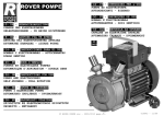
Event
Event type
0Y. diagnosis
WW .10Loop
.T1 W
M
● shows that the ON/ The event is turned ON when any change
O
W
in PV corresponding to increase/decrease in MV (Manipulated
OFF is changed at variable) is not W
WW .100Y.C M.TW
.T observed.
this value.
M
This event
is used to detect any fault of W
devices.
.CO .TW
W final control
.CO items
Y
shows that the ON/ ●
W
0
Y
W
Setting
0
0
T
.
0 • Main setting:
M
.1
OFF is changed
OM MV (Manipulated variable)
W.1at Y
WW 00Y.CO .TW
C
a point W
that "1U" is
.
W
•
Sub-setting:
PV
W
Wto this value.
.T Diagnosis time
00 • ON delayMtime:
added
W.1 Y.COM W
O specifications
W.1 ● Operation
W
C
.
W
0
Y
W
.T
W
W
.TW
.10reach
.100The eventOisM
turned ON when the value does
the PV
set in the sub-setting within the diagnosis
OM
Wnot
M.T
W
C
.
O
W
C
.
timeY
even though the
held.
WMV exceeding
.TisW
W
00theYmain setting
0 (ON delayMtime)
Y.C
WW .●1CAUTION
TW
.
1
0
0
T
M
.
.
0
O
1
W
M
.
O
W
C
.
O
W
W
.C the ON.Tdelay,
setup".W
W it is necessary
.C
Ysetting
W to put in.1"Multi-function
00Y
WW .When
M.T
.TW
The
of the ON delay before shipment
is 0.0s.
100default setting
00Y
M
O
1
W
M
.
O
W
C
W
.CO .TW
action
WW .100Y.
TW action
.Reverse
WW .100Y.C Direct
.TW
M
00Y
M
O
1
W
M
.
Heat
Cool control
W control O
WW .100Y.C M.TW
WW 00Y.CO .TW
WW .100Y.C M.TW
O
W
M
.1
O
W
Y.C Area satisfying
WW .100PV
WW 00Y.CO .TW
.TW
WW .1PV00Y.C M.TW
M
conditions
1
HYS
O
1
W
M
.
Sub-setting
Sub-setting
O
W
.C
O
W
W
C
Area
satisfying
W
.
Y
W
C
W
.
0
Y
W
T
W
W
W
M.
.10
.TW
100conditions 1 OM.T
00Y
.
O
1
W
M
.
W
C
O
W
HYS
WW .100Y.
.TW
WW .100Y.C M.TW
WW .100Y.C M.TW
M
O
W
O
W
O
W
W
Y.C
Time
.TW
WW .100Y.C M.TW Time W
100
WW .100Y.C M.TW
M
.
O
W
O
W
C
.
O
W
satsifyingTW
Y.Csatisfying
WW MV.100Y Area
WWMV .100Area
conditions
2
conditionsM
2 .
.TW
WW .100Y.C M.TW
M
O
W
O
W
C
.
O
W
W
C
.
Y
Main setting
Main setting
W
.TW
WW .100Y
.TW
100
WW .100Y.C M.TW
M
.
M
O
W
O
W
O
W
WW .100Y.C M.TW
WW .100Y.C M.TW
WW .100Y.C M.TW
O
W
O
W
O
W
W
Time
0Y.C3 M.TW Time
Y3 .C
WW .10Conditions
0
WW .Conditions
T
.
0
WW .100Y.C M.TW
1
M
O
O
WW 0ONset0delay
W
.CO .TW
Y.C ON .TW
WW ONset delay
C
.
W
W
time
time0Y
W
Y
W
1
0
0
ON
W
M
.
.T
0
EV
EV
W.1 Y.COM Time W
Time
WW 00Y.CO .TW
W.1 Y.COM W
W
W
W
0
W
T
ON delay is started
when conditions 1 and
2 are satisfied.
On delay is started when0
conditions 1 and 2 are.saisfied.
1
0
W
T
M
.
.
1
0
O
W
OM
W.
OM
W.1
WW .100Y.C M.TW
WW .100Y.C M.TW
WW .100Y.C M.TW
diagnosis 2
W
O
WW 00Y.CO .TW
W
.CO Loop
W
C
W
.
Y
W
W
W
0
Y
W
T
any
(Manipulated
0 change in PV .corresponding to increase/decrease
W
M
.TThe event is turned ON when
00
W.1 in MV
W.1 Y.COM W
is not observed.
.CO .TW
W
W.1 Y.COM variable)
Y
W
0
W
W
Wevent is used W
0
This
to detect any1fault
.Tdevices.
00 of final control
W
W.1 Y.COM W
M.●TSetting items
.100
OM
W.
O
W
W
C
.
W
C
W
.
W
.T
W setting: MVW
00
0Y
• Main
(Manipulated variable)
.T
WW .100Y
M
.10the
W.1 Y.COM W
M.T
• Sub-setting: Change in PV
from
point
that
the MV exceeds the main setting.
O
W
O
W
W
C
.
W
W
• ON
delay time: Diagnosis
WW time .100Y
WW .100Y.C M
M.T
.100
.TW
M.T
O
W
● Operation specifications
O
W
C
.
O
W
W
Y does .TW
W MV0exceeding
Y.C
The event
main
setting is held W
(conditions 2)1and
.TW
WW .100Y.C M
M
. 00 the PV O
.TW is turned ONWwhen the
1 0is addedOthe
.
W
not reach the value that the sub-setting
toM
(subtracted from) the PV at the
point where the
W
O exceeds the main setting within
W
W
.Ctime (ON .delay
Y.C MV .TW
W the diagnosis
C
W
.
0
Y
time) (conditions
1).
W
W
W
0
0
Y
W
T
W
00
M
.10
W.1 Y.COM W
M.T
O
W
W
W.1 Y.C●OCAUTION
C
.
W
When setting
the
ON
delay,
it
is
necessary
to
put
in
"Multi-function
setup".
W
Y
W
W
.T
W
M.T
.100
.TWsetting of the W
100shipmentOisM
00
.
TheM
default
ON delay before
0.0s.
O
1
W
.
W
C
O
W
W
Y.
Waction
.TW
Reverse
WW .100Y.C M.TW
100
WW .100Y.C M.TW Direct action
M
.
O
W
O
W
Heat O
control
Cool control
W
WW .100Y.C M.TW
WW .100Y.C M.TW
WW .100Y.C M.TW
OPV
WW 00Y.CO .TW
W
WW 00Y.CO PV.TW
C
.
W
W
W
Y
W
W
M
.1
.T
00
.1
HYS
OM
W
WW 00Y.CO .TW
W.1 Y.COM W
C
.
PV
to be used
W
W
Sub-setting
Y
W
W
Area satisfying
W (0 or .more)
Area satisfying
1
00 as reference .T
W
.Sub-setting
conditions 1
OM
conditions 1 W (0 or more)
.10PV0to be usedOM.T
W 1 Y.COM W
C
.
W
W
W
HYS
Y
W
C
as
reference
.
W
W
.T
WW .100Y
M.T
.100
.TW
100
M
.
O
W
M
O
W
C
O
W
.C
W
WW Time .100Y.
.T
WTime
.TW
00Y
WW .100Y.C M.TW
1
M
.
OM
W
O
W
C
.
O
W
W
C
Y
Area satisfying
.
Y.C
WW .100Y. MV M.TAreaWsatisfying conditions 2 W
WW .100MV
conditions
2
.100
.TW
OM
W
M
O
W
C
.
O
W
W
C
.
Y
W
C
W
Y
W
Main setting
W
Y.
W
WW Main .setting
M
.100
M.T
.100
100
W
M.T
O
W
.CO
O
W
W
C
.
Y
W
C
W
.
0
Y
W
W
W
0
Y
W
.T
W
.100
W.1 Y.COM
M.T
.100
OM
W
O
W
W
C
.
W
C
W
Y
W
Time W
Time
WW .100Y. ConditionsM3 .TW
.100
Conditions
M.T3
.100
W
O
W
O
W
ON
delay
W
C
ON
delay
WON
.C
W
W
WW .100Y.
set time.T
WW EV
00Y set time M.TON
M
1
EV
.
O
W
O
Time
Time
W
.C
0Y.isCstarted when
WW .1ON0delay
TW 1 and 2 are satisfied.
.conditions
started when conditions
1 and 2 are satisfied.
WW ON.delay
.TW
00is Y
M
1
M
O
W
O
W
WW .100Y.C
WW .100Y.C M.TW
W
O
W
WW
WW .100Y.C M.TW
O
W
WW .100Y.C M.TW
O
W
WW .100Y.C
W
4
WW
W
M.T
O
.C
W
00Y
1
M.T
.
O
W
C
. diagnosis
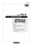
Event
Event type
WW .100YLoop
.TW1
M
O
● shows that the ON/
W
The event is turned ON when
in PV
to increase/decrease in MV (Manipulated
.C corresponding
Wany change
OFF is changed at variable) T
.TW
not observed. W
00Y
. is W
1
M
.
this
value.
M
O
Wof final control
.
This
fault
devices.
O event is used to detect any W
W
shows that the 0
ON/
0Y.C M.TW
Y.C● Setting .items
W
0
T
1
0
.
1
Msetting: Change in PV from
.
OFF is changed
at
O
•O
Main
the
MV reaches the upper limit (100%) or lower limit (0%).
Wpoint thatY.the
C(PV
W
W
a point
that "1U" isY.C
WW
WRange of absolute
0
• Sub-setting:
value of deviation
– SP)
W
0
0
W
T
.
1
0
M.Tallowing the event to turn OFF.
added to this.1
value.
M time: Diagnosis time WW.
• ON
delay
O
O
W
C
.
W to turn OFF.
Y
•C
OFF delayT
the.T
event
W A period of time
W from power
WW .100●Y.Operation
. time:
100ON allowing
M
.
.TW
M
specifications
O
W
M
O
W
C is turned
O
W control. 0The
.C direct action
• The
ON when the increase in PV becomes
Wis used for theWheat
0Y.event
.TW
W
Y.C
WW .100Y
T
.
1
0
T
M
.
.
0
smaller
than
the
main
setting
after
the
diagnosis
time
(ON
delay
time)
has elapsed from the time that the MV
M
O
1
W
M
.
O
W
C
.
O
W
W
W than the main setting from the
.Creached the
had
upper limit, or when
the decrease0in
YPV becomes.Tsmaller
W
C
W
.
Y
W
W
0
0
Y
W
T
.
.T
has.1elapsed fromO
theM
time that the MV had reached the lower limit.
10 time thatOtheMdiagnosis time (ON delay time)W
00
.
1
M
.
W
C
. turned.ON
W
C action
is used for the cool
control. The0event
when the decrease in PV becomes
W
.CO .TW
Y.reverse
WW
TW
0 Y(ONisdelay
WW .10• 0The
1time
M
.
smaller thanM
the.T
main setting after the diagnosis
time) has elapsed from the time that the
00Y
O
1
W
M
.
O the upper limit, or whenWthe increase Y
W
C becomesTsmaller
had
in .PV
W than the main setting after
.Creached
W
W
WW 00Y.CO .TW
. MV
00the
0Y
WW .10MV
1
the
diagnosis M
time.T
(ON delay time) has elapsed from
time that
the
had reached the lower limit.
M
.
W
M
.1
W • The event
.CtheOabsolute
regardless of other
when
value
Wconditions
W of the deviation (PV – SP)
.CisOturned .OFF
Y
W
0
Y
W
T
WW 00Y.CO .TW
.
0
0
WW .becomes
T
than the sub-setting.
10 eventless
M
OM
W.1 when
W• The
is O
turned OFF regardless of otherW
conditions
a period of time
.C
W.1 Y.COM W
C
W after starting of operation
.
Y
W
W
0
Y
W
W
0 less thanM
0 time thatM
W
from
the
the.T
power has been turned ON becomes
the.T
OFF delay time.
1
0
0
W
T
.
.
1
0
.
O
1
O is turned OFF when the absolute
WHowever, Y
the
OM
WWvalue0of0Ythe.Cdeviation .isTthe
W.
W(sub-setting – hysteresis)
.Cevent
W value of theWdeviation
WW value
T
or0less after the absolute
has
become the M
sub-setting or more.
.
1
0
WW .100Y.C M.TW
.
1
O
OM
● CAUTION
W.
O
WW to0put
W
Yin.C"Multi-function
WOFF delay, it W
0
Ythe.CON delay.T
.TWsetup".
and
is necessary 1
0
WWWhen setting
0
WW .100Y.C M.TW
M
.
1
M
.
O
W
TheW
default settings O
and OFF delayW
before shipment.C
are 0.0s.
O
W
Cof the ONTdelay
W
W
00Y Reverse
WW .100Y.Direct
. W
action
1
WW .100Y.C M.TW
M.Taction
.
M
O
W
O
W
O
W
HeatW
Cool control 0Y.C
WW
.TW
W control .100Y.C M.TW
10
WW .100Y.C M.TW
M
.
O
W
O to be used
W
Main setting (0 or more)
O
W
WW .100Y.C M.TW
WW .100Y.C PVM
.TW
as reference
WW .100Y.C M.TW
OMain setting (0 or more)
PV W
PV
O
W
CO Area satisfying
Y.C
WW 00Y.HYS
W Main
WW .10Area0satisfying
.TW HYS
W
T
setting
.
WW .100Y.C M.TW
M
1
conditions 1
PV to be
conditions 2
M
.
Main setting
O
(0
or
more)
W
Area
satisfying
satisfying
used as
O
W
W
W1 (0 or more)
Y.CHYS Area.conditions
PVW
to be
WWconditions020Y.CO .TWHYS
C
.
reference
0
T
W
W
0
Y
W
used
as
1
0
W
M
.
.T
0
.1 Main setting M
(0 or more)
reference
WW 00Y.CO PV to be.TusedW
W.1 Y.COM W
as reference
WW 00Y.CO .TW
W
W
W
1
W
M
.
.T
Time
Time
1
00
M
.
O
1
W
M
.
O
W
.C
O
W
W
C
W
.
Y
W
C
W
.
0
Y
W
T
W
.
W
0
Y
W
.T
W
MV
MV
.100
W.1 Y.COM W
M.T
.100
OM
W
O
W
W
C
.
Upper
Upper
W
C
YArea satisfying .TW
W
satisfying .T
W limit
00 Area
W
limit
WW .100Y.
conditions
2
2 M
.100 conditionsO
OM
W.1 Y.C
M.T
W
O
W
W
C
Area
satisfying
Area
satisfying
.
W
C
W
.
0
Y
W
W
.TW
conditions
2
WLower
0
0
Y
W 2
T
conditions
.
1
0
0
W
T
M
.
.
Lower
1
0
M
.
O
1
W
O
W
limit
limit
OM
W.
Y.C
WW
TW
Time.TW
0Y.C
WW .10Conditions
100 Conditions 3 OM.Time
WW .100Y.C M.TW
Conditions 3 W.
Conditions 3
3
M
O
W
.C
ON delayW
ON
O
ON delay
ON delay .C
W
W
Ydelay
W
W
set
time ON
set timeW
set 0
ON
100set time ONOM.T
0timeYON M.TW EV
WW .100Y.C M.TW EV
.
1
.
W
Time
O
W
W
.COTime .TW ON delay is W
Y.2Care satisfied.
WW 002Y
.TW
started when conditions
are satisfied.
001 and
1
WW .100Y.C M.TW ON delay is startedWwhen conditions.11 and
M
.
M
O
W
O
W
C
O
W
WW .100Y.
.TW
WW .100Y.C M.TW
WW .100Y.C M.TW
M
O
W
PVO
alarm (status)
O
W
WW 00Y.C
WW .100Y.C M.TW
Waction
.TW
WW .100Y.C M.TW
Direct
Reverse action
1
M
.
CO
.occurs,
OON if PV alarm (alarm code AL01
WW
W
.CO OFF
Y
WW
C
to 99) occurs,
ifW
PV alarm (alarm
code
AL01 to 0
99)
.
Y
W
W
.TW
W
0
0
Y
W
T
.
1
0
W
M
.
1
00
OFFM
in.T
other cases.
ON in other cases.
M
.
O
1
W
.
O
W
O
W
.C (status)
WW .100Y.C M.TW
READY
WW .100Y
.TW
WW .100Y.C M.TW
M
Direct action W
Reverse action
O
WW 00Y.CO .TW
W
.CO .TW
W
C
.
Y
W
W
W
0
Y
W
0
W
M
.T mode.
00 ON in the
Min the READY mode. WW.1
MREADY
O
W.1 Y.COFF
.CO .TW
O
W.1 YOFF
in the RUN mode.
ON in the RUN
mode.
Y
W
C
W
.
0
W
W
W
0
W
.T
00
W
(status)
W.1 Y.COM W
M.T
.100
OM
W.1MANUAL
O
W
W
C
.
W
C
W
.
Y
W
Reverse action
.T
WDirect actionW
00
.T
WW .100Y
.100 OFFOinM
W.1 Y.COM
M.T mode.
W
ON in the
MANUAL
the MANUAL mode.
O
W
W
C
.
W
W
Y
W
W
W
mode.
RUN .mode.
0Y.inCthe AUTO
WW .10OFF
M.T
.100
MT
.100 ON inO
O
W
M.T
W
C
.
O
W
W
C
During AT (Auto
Y
Y. tuning) .TW
W
.
W action WW
WW .100Y.C M.TDirect
.100
100
M
.
Reverse action
OM
W
O
W
C
.
O
W
W
C
.
Y
W
C
W
W
while
running.
0Y while ATMis.T
Y. AT is running.
W
WW ON
M
.100
.TW
.10OFF
W
.100while AT O
OFF
is M
being stopped.
ON while O
AT is being stopped.
W
.CO
W
W
C
.
Y
W
C
W
.
0
Y
W
W
0
Y
W During.SP
W
.TW
100ramp OM.T
W.1 Y.COM
MDirect
.100
W
O
W
W
C
action
Reverse
action
.
W
C
W
Y
W
W
Y.
W
WW ON during
.100
100during SPOramp.
M.T
.OFF
W
M.T
.100 SP ramp.
W
O
W
W
C
. ramp is .not
C is not performed
SP .ramp
or is completed.
performed or isW
completed.
0YSP
WW ON.1when
TW
0(status)
WWOFF when
.TW
00Y
M
1
M
.
Control
operation
O
W
O
W
WW .100Y.C Reverse
.TWaction
action
WW .100Y.C Direct
.TW
M
M
O
W
W directYaction
.C action (cooling).
ON
during Y
direct
.CO(cooling).
Wduring
W
0reverse
WWOFF
0
0
WOFF
T
.
during1reverse
action (heating).
ON during
action (heating).
1
0
.
M
O
W.
WW
C
.
W
W
Y
W
W
.T
00
W.1 Y.COM W
W
W
.T
00
W.1 Y.COM
W
W
.100
W
5
WW
W
M.T
O
.C
W
00Y
1
M.T
.
O
W
C
W(Smart Tuning)
Y.
Event
Event type
standby
WST
.TW (status)
100 setting
M
.
● shows that the ON/
O
W
Direct action
Reverse action
OFF is changed at
W standby. WW .100Y.C OFFM
TW
.Tsetting
ON in theM
ST
in .the ST setting standby.
this value.
O
W
O
setting completion. W
the STW
shows that the ON/ OFF
W
0Y.CON in M
Y.Cin the ST.T
W
.T setting completion.
0
0
1
0
.
OFF is changed
at
Timer
(status)
1
M
.
O
W
O
W
.Ctimer event.
W disabled0for
C and reverse
a point W
"1U" is
action settings
0Ythe
Ware
.TW
0Y.direct
Wtothat
TWevent,
.timer
1
0The
added
this value.
M
.
1
M
.
When
using
the
it
is
necessary
to
set
the
operation
type of the DI allocation to "Timer Start/Stop".
O
W
O
W
C
.
.C when.T
setting
allocation,
W the event channel
WW designation
.TW multiple timer events are
00Yof the DI M
WW .1Additionally,
00Y from
.TW
M
controlled
individual internal contacts (DI).W.1
O
M
O
W
O
.Citems .TW
WW .100Y.C M.TW
W
0Ydelay
Y.C
WW .●1Setting
0
0
T
.
0
•
ON
time:
A
period
of
time
necessary
to change the event from OFF to ON after DI has been
M
1
O OFF to ON.
OM
WW 00Y.CO .TW
W.
.Cfrom
WW changed
C
W
.
Y
W
W
0
Y
W
T
.
0 delay time:MA period of time necessary toW
M ON to OFF after DI has been
.1 the eventOfrom
.T
change
00
O
W.•1OFF
.C
W
W.1 Y.COM W
C
changed
from ON to OFF.
.
Y
W
W
0
Y
W
.TW
0
W ● Operation
.T
1
00 specifications
M
.
.T
1
00
M
.
O
1
W
M
.
O ON when DI ON continues
WThe event
.C or longer.
turned
Ytime
WWfor ON1delay
WW 00Y.CO .TW
.TW
00delay
0Y.isisCturned
WW •• The
TW
.
0
event
OFF
when DI OFF continues for .OFF
time M
or longer.
1
M
.
O
1
W
M
.
O
W
C
• In other cases, the current status is continued.W
Y.
W
WW 00Y.CO .TW
.TW
WW .100Y.C M.TW
100
M
.
O
1
W
M
.
O
W
O
W
ON
WW .100Y.C M.TW
WW .100Y.C MDI .TW
WW .100Y.C M.TW
O
W
O
W
Y.C
WW 00Y.CO .TW ON delay WW
C
.
0
W
OFF delay
.TW
W
0
Y
W
1
W
M
.
.T
1
00
M
.
O
1
W
M
.
O
W
O
W
Y.C
ON
W
WW
.TW
WW .100Y.C
Internal event .T
100
WW .100Y.C M.TW
M
.
M
O
W
O
W
O
W
WW .100Y.CTime M.TW
WW .100Y.C M.TW
WW .100Y.C M.TW
O
W
● CAUTIONW
O
W
.COand OFF
W
W it is necessary
0Y.C M
Ydelay
When
setting the ON
delay,
setup".
WWto put in.1"Multi-function
.TW
0
0
W
T
.
0
WW .100Y.C M.TW
1 of the ONOdelay
M
.
The default W
settings
and OFF delay before shipment
are 0.0s.
O
W
O
W
C channel
Y.Cshipment.TisW
W setting 0of0the
The W
default
designation of the
DI allocation
"0". In this
Y.event
WW
00before
.TW
1one
WW .100Y.C M.TW
M (DI).
.
1
M
.
case, the timer event
start/stopO
can
be set for all internal events W
from
internalO
contact
W
C
O
W
Wset for one
Y.
Additionally,
set,W
the timer event
can
Wdesignation is W
Y.Cevent channel
.Tbe
WWas one.1or00more
.T
100 start/stop
WW .100Y.C M.TW
M
.
internal event specified
by one internal
contact (DI).
M
O
W
W
.Cin "Multi-function
O
Wnecessary0to0Y
W
W setup".
.CO
However, when
event
channel of W
it is
put
0Y
WW setting.1the
T the DI allocation,W
.
1
0
WW .100Y.C M.TW Direct/Reverse
M.T
.
M
O
action,
standby, and READY
operations can be set when
setting up each
event (E1.C1 to
W
O
W
C
O
W
.C
W
WW .100Y.
.TW
.TW
00Y
WW .100Y.C M.TWE5.C2). W
M
1
M
.
O
W
O
differential 0 to 9999 or 0.0 to 999.9
W
W Operating
.CO
WW .100Y.C M.TW
WW .100Y.C M.TW
WW .1Output
ON/OFF operation
00Y operationM.TW
O
W
W
O
W OutputYtype
.CO .TW contact forW2 W
Y.C
SPST relay contacts,W
Common for 3Ycontacts/independent
contacts
C
.
0
W
.TW
W
0
0
W
1
0
W
M
.
1
00 rating M.T250Vac/30Vdc, 2A (resistive
M
.
O
1
W
Output
load)
.
O
W
O
W
WW .100Y.C M.TW
WW .100Y.C M.TW
WW Life.100Y.C M.100,000
TW cycles or more
O 5V, 10mA
WW 00Y.CO .TW
W
Min. opening.C
and
WW 00Y.CO .TW
W
W
W
Y
W
0
W closing
M
.1
.T
0specifications
W.1 Y.COM W
OMCommunication protocol W
WW 00Y.CO .TW
W.1 Ysystem
C
CommunicationW
Communication
RS-485
.
W
W
W
.T
00
W
.1
.T
OM
M
.100
Network
Multidrop,
provided with the slave station W
function.
OisM
W.1 This device
C
.
O
W
W
C
W
.
Y
W
C
W
.
0
Y
W
0
W1 to 31 units
.T
WW .100Y
TW
M.T
.10
.flow
10max.
M
.
O
W
M
O
W
C
Data
Half-duplex
O
W
.C
W
WW .100Y.
.TW
.TW
00Y
WW .100Y.C Synchronization
M
Start/stop synchronization
.TW method W
1
M
.
O
W
M
W
O
.CO .TW
Interface
system
Balance
WW .100Y.C M.TW
WW 00Y.CTransmission
W
0Ytype
WW (differential)
0
W
T
.
1
M
.
M
Bit serial W
Oline
WW 00Y.CO .TW
W.1 Y.Data
.CO .TW
W
C
Y
W
W
W
0
W
3 transmit/receive
W
.T lines
00 Communication
.10lines
W.1 Y.COM W
OM
W
OM speed
W
W.1 YTransmission
C
.
4800, 9600,
19200, 38400
bps
W
C
W
.
Y
W
W
W
W
.T
00
W
M.T
.100
.Tdistance
00 Communication
M
O
500m max. W.1
1
W
M
.
O
C
.
O
W
.C
W
WW .100Y
.TW
(3-wire type) 00Y
Y.C
.TW
WW .100Protocol
M
.TW RS-485W
1
M
.
O
W
M
O
W
Message characters
bits/character
W Character
COconfiguration
WW .100Y.C M.TW
W 11
WW .100Y.C M.TW
0Y.length
WW .10Data
T
.
7
or
8
bits
W
OM
WW 00Y.CO .TW
W Stop Y
.CO .TW
Y
W
W
bit.C
length
1 or 2 bits WW
W
0
0
W
M
.1
.T
00
OM
W.1or non-parity
parity,
WW 00Y.CO .T
W.1Parity bitY.COM WEven parity, oddW
C
.
W
Y
W
W
W
.T
00
W line 3-wire
Loader
Communication
W.1 Y.COM
M.T
.100
W.1 Y.COM W
Obps
W
communication Transmission speed WFixed at 19200
W
C
.
W
W
.
Y
W
W
.100
.TW
M.T
.100
OM
W
.100 cable,O2 M
Recommended cable W
Dedicated
m long
O
W
C
.
W
C
.
Y
W
C
W
Y
W
W2
Y.
W
Current
Number of inputsW
M
.100
.TW
M.T
.100
100
W
M
.
O
W
transformer
.CO
O
W
W
C
.
Detection function W
Control output .isCON.: Detection of heater line break
or overcurrent
Y
W
W
0
Y
W
0
Wdevices short-circuit
input
W Control.1output
.TW of final control
Detection
00Yis OFF.: M
M.T
.100
W.1 Y.COM
O
W
O
W
W
C
.
W
C
Input object
Number of current
windings:
800 turns
W
Y
W
W
Y. transformer
W
WW
.100
M.T
.100
QN206A .(5.8mm-hole
diameter)
100
W
M.T Optional
O
W
O
W
W
C
Optional
W
W (12mm-hole
WW .100Y.
.TW
0Y.Cdiameter)
WQN212A
.TW
M
M
Measurement current 0.4 to 50A.10
O
W
O
W
range
WW .100Y.C M.TW
WW .100Y.C M.TW
O
W
Indication range
0.0 to 70.0A
O
W
WW .100Y.C
WW digit.100Y.C M.TW
Indication accuracy
±5%FS±1
W
O
W
WW
WW .100Y.C M.TW
O
W
WW .100Y.C M.TW
O
W
WW .100Y.C
W
6
WW
W
M.T
O
.C
W
00Y
1
M.T
.
O
W
Current
Indication resolution 0.1A
C
Y.
WW .100output
.TW
transformer
Output
Selected from control output 1 and control
2, orM
event output 1, event output 2, and event output 3.
O
W
input
C or more
W
Min. detection time
Burnout detection:
output ON0time
0Y.300ms
WW
.TW Min. control
1
M.T OFF time 300ms or more
.
FinalM
control device short-circuit detection:
Min.
control
output
O
W
O
C
C
WW .100Y.
General
Memory backup 0Y. Semiconductor
.TW
.TWnon-volatile memory
0
M
1
M
.
O
specifications Power supply
W
O
W voltage AC
model: 85 to 264Vac,
W 50/60Hz±2Hz.
W
.Cpower supply
Y.C
WW .100YDC
.TWmodel: 21.6 toW26.4VacW50/60Hz±2Hz,
100
Mto.T
.
power
supply
21.6
52.8Vdc
M
O
O
W
C
.
W
Y
W
Power
AC.C
power supply
model: 12VA orW
less.
Y
.TW
Wconsumption
.TW
105W0 or lessO
00DC
M
.
.TW
1
M
.
W
M
power
supply
model:
72VA
or
less
(24Vac),
(24
tp
48Vdc)
O
W
W
W
W terminal andWsecondary
.CO .TW
0Y.C500Vdc,
Y.C power .supply
.TWor more
0
0
Y
W
T
Insulation
resistance
Between
terminal,
10MΩ
1
0
0
M
.
1
0
M
.
O
1
W
.C
OM
W.
W
.COsupply .model:
power
supply terminal
terminal, 1500Vac for 1 min.
WW AC
WW
W DielectricWstrength
00Yand secondary
0Y
Y.C
TW Between power
1
0
0
T
M.T terminal, 500Vac for 1 min.
.
.
1
0
M
.
O
1
DC power supply
model: Between power supply
terminal andCsecondary
W
M
.
O
W
W
W
Y.
.CO .TW Power ON inrush
Wpower
TW
0Y.CsupplyMmodel:
current AC0power
supply
or .less.
WW
.TW20A or less. DC
100model: 20A
M
.
1
00Y
.
O
1
W
M
.
WAmbientYtemperature
.Cmounting).TW
W for side-by-side
.CO .TW0 to 50°C (0 toW40°C
WW 00Y.CO .TW Operating conditions
00Y
0 humidity
WW Ambient
1
0
M
.
1
10
to
90%RH
(No
condensation
allowed)
M
.
M
.1
W
.COof X, Y,.Tand
WW 00inYeach
WZ directions)
.CO .TW
Y
W
WW 00Y.CO .TW
resistance
0 to 2m/s (10 to
60Hz for 2 hrs.
0
WW Vibration
1
0
M
.
1
M
.
O
1
W
M
.
O
W resistance
Shock
0 to 10m/s
O
W
W
Y.C
WW .100Y.C M.TW
WWMounting
.TReference
00angle
WW .100Y.C M.TW
plane ±10°
1
M
.
W
O
WW 00Y.CO .TW
W
.CO -20
W
C
Transportation
Ambient temperature
to +70°C
W
.
Y
W
W
W
0
Y
W
T
.
1
0
W
M
.T
00
W.allowed)
Ambient
95%RH (No condensation
W.1humidityY.COM10 to W
.CO .TW
W
W.1 Y.COM conditions
Y
W
0
W
W
WPackage .drop
.T height, 60cm, (1 corner, W
Drop
3 sides,
W
M fall)
.10 6 planes,Ofree
.TW
100test OM
MMask
.100
W
C
.
O
W
W
C
W
.
and
case
Mask:
Polyester
film,
Case:
Modified
PPE
Y
W
C
W
.
Y
W
W
.T
WW .100Y
M.T
.100
.TW
material
100
M
.
O
W
M
O
W
O
W
and
Light
Wgray (DIC650)WW .100Y.C M.TW
Wcase color Mask:
0Y.C Case:
WWDark gray
.T
0(DIC546),
WW .100Y.C Mask
T
.
1
M
.
M
IP66
W
OStructure
WW 00Y.CO .TW
W
.CO .TW
W
C
.
Y
W
W
W
0
Y
W
Conformed
EN61326
W
M
.1
.T standards EN61010-1, W
00
.10
OM
OM category CategoryW
WW 00Y.CO .TW
W.1 Y.CInstallation
C
.
II (IEC644-1, Y
EN61010-1)
W
W
W
W
0
W
.T
1
W
M
.T
00 Mounting
.10 (mounting
S type: SocketW
mounting
OMwith dedicated socket) WW.
.CO .TW
OM
W.1 Y.C
C
.
Y
W
W
T
type:
Panel
mounting
(with
dedicated
mounting
bracket)
0
Y
W
W
W
0
W
.T
W
.100
W.1 Y.COM W
M.T
.100 Weight
OM
S type: Approx. W
200g (including
socket)
O
W
W
C
.
W
C
W bracket)W
.T
W 150g.1(including
00Y dedicated
WW .100Y.
.100
.TW T type: Approx.
M.Tmounting
OM
W
M
O
W
C
.
O
Standard
Part
name
Model
Q'ty
Auxiliary
parts
Part
name
Model
W
W
C
W
Y
W
W
0Y1. (optional
Y.C bracket
WW
.TW
parts) Mounting bracket
accessories 00Mounting
W
M.T
.100
.TW
81446403-001 .10
81446403-001
M
O
1
W
M
.
O
W
C
.
O
W
W
Y
CP-UM-5287E
.TW
WW .1001Y.C M.TW Gasket W
100 81446918-001
0Y.CmanualM.TW
WW .10User's
M
.
O
W
O
W
Current transformer
QN206A.C
(6mm-hole diameter)
W (Installation)
W
.CO .TW 81446918-001
WW QN212A
.Tdiameter)
00Y (12mm-hole
WW .1010Y.C M.TW
1
WW .1Gasket
M
.
00Y
O
W
WC15T. Y.CO
OM
W
W
Y.C
Wwith
Supplied W
only
WW .10081446391-001
0
.TWSocket
0
WW .100Y.C M.TW*1
M.T
1
M
.
O
W
*2
Connected
to
C15T.
Hard
cover
81446442-001
O
W
O
W
W cover
0Y.C M.TW
WW .1081446443-001
WW .100Y.C M.TSoft
*3 Standard accessory
WW .100Y.C M.TW
O
W
O
W
W
Terminal
cover
81446898-001
W
Y.C
WW 00Y.CO .T
C
W
.
0
W
W
W
0
Y
W
M.T
.1
.T
1
00 and Ranges
M
.
Table 1WInput Types
O
1
W
M
.
O
W
C
O
Y.Ctype C01
WWRange.1(°0C)0Y. RangeM(°.F)TW
WW 00Y.C
W(°W
.TW
00Input
Input typeWC01 No. 1Sensor
type
Range
(°C)
Range
F)
No. Sensor type
.TW
1
M
.
W
M
.
COto +900TW
.CO .41
Y.-300
WW 00Y
Thermo1W
KY.CO-200 to +1200
-300 to +2200
RTD
Pt100 WW
-200 to +500
W
0
W
W
0
W
T
1
0
W
T
M.
.
.
.1
O+900
W+500
couple
2
0M
to 1200
0 to 2200
JPt100
-200 to
-300
to
.10 K
OM 42
W
C
.
O
W
W
C
W
.
Y
W
C
to 800
+200
+400
W3W .10K0Y. 0 M
M.T
.100 -300 to O
.TW 0 to 1500W W.100Y OM43.TW Pt100 W-200 to W
4
44
-200W
to +400
W
Y.C
W to +200.100-300
WW K00Y.CO0 to 600.TW 0 to 1100 WW
0Y.C M
TW JPt100
.
0
W
M.T
1
5
K
0
to
400
0
to
700
45
Pt100
-100
to
+300
-150
to +500
.
O
1
W
M
.
O
W
C
.
O
W K Y.-200
.C 46 .TWJPt100 -100
WtoW+300 .1-150
6 W
+400 W-300 to +700 WW
00Yto +500 M.TW
00Y
0 C to M
W
T
.
1
0
M
.
1
W
.
O
W
9
J
0 to 800
0 to 1500
Pt100
-50.0 to +200.0
-50 to +400
.CO .TW
W
W
0toY+400
Y.C 51
W
WWJ 00Y.0CtoO600 .TW0 to 1100 WW
0
0
T
.
1
0
10 W
52
JPt100
-50.0
to
+200.0
-50
.
OM
W
M -300 to +700
.1 -200 toO+400
W.1 Y.C53OM Pt100
C
.
W
W
W
Y
11
J
-50.0
to
+100.0
-50
to
+200
W
C
W
.
W
W
WW E .100Y0 to 600 M.TW
.10to0+200 OM.T
100 54 OM.TJPt100 -50.0 to +100.0 W-50
.
13
0 to 1100
W
C
O
W
C
0Y.
WW 0.1to0400
.T
14
WW .100Y.63
TW 0.0 to 200.0
.Pt100
0Yto.C+400 M.-300
WWT .10-200
TWto +700
M
OM
W
O
W
C
.
O
15
R W
0 to 1600
0
to
3000
64
JPt100
0.0
to
200.0
0
to
400
W
C
.C
.
00Y
WW .100Y67.
.TW 0 to 500W W
WW
16
S
3000
Pt100
0 to.1900
00 0toY1600 M0.TtoW
M
OM
1
.
O
W
C
.
O
W
W
C
.
Y
W
C
W 0 to 500 W 0 to 900
17
0 to 3300
68
JPt100
Y
Y.
W
WNBW .0010toto01800
M
.100
.TW
M.T
.100
W
M
18
1300
0 to 2300
O
W
.CO
O
W
W
C
.
Y
W
C
Input
type
C01
No.
Sensor
type
Range
W
.
0
Y
W
W
W
0
Y
W
.T
20
Wre5-26
0 to01400
0 to .2400
W
100
W.1 Y.COM
MT
.1 0
Linear inputW. 84
0O
toM
1V
W
C
21
Wre5-26 WW
0 to 2300 .CO0 to 4200
.
W
W
Y
W
W
0Y -300M
W -200 .to10+400
TW
.100
a range
M.TThe scaling is made inW
.18600 1 toO5V
24
DIN U
ot .+700
W
W
O
W
C
87
0
to
5V
W to +9999. W
.C
25
DIN L WW
-100 to +800
+1500
WW 88.100Y.0 to 10VM.ofThe
T-1999
.TW
00Y -150 toM
decimal point position can
1
.
O
W
O
W 89 000Yto.C20mA be.Tchanged
C
W variably.
.
Handling Precautions WWW
W
Y
W
0
.T
1
0±5%FS
M
.
1
M
.
• The accuracy of the B-thermocouple
is
at
a
temO
W
90
4 to 20mA
O
WW at a00temperature
Y.C
WW .100Y.C
perature of 260°C or less and
of.TW
W±1%FS
1
M
.
W
260 to 800°C.
O
WW 00Y.toCthe
W
WW
T
• The range having the decimalW
point is displayed
1st
.
M
.1
digit after the decimal point.
WW 00Y.CO .TW
W
• The setup is made using C01 No. according
to the sensor
W.1 Y.COM
type and range to be used.
W
W
.100
W
7
WW
2
2
*1
*2
*3
*1
W
M.T
O
.C
W
00Y
1
M.T
.
O
W
C
■ Model Selection Guide
W
WW .100Y.
M.T
O
W
I
II
III
IV
V
VI VII
Example: C15TR0TA0000
WW .100Y.C M.TW
.TW
M
I
II
III
IV
WW 00Y.CO .TW
.CV O .VITW VII
Y
W
0
Basic Mounting Control
PV
Power M
Option Additional
M
.1
.10 supply
O
processing
model
outputWW
input
WW 00Y.CO Specifications
C
W
.
W
Y
W
W
No.
M.T
.1
M.T
.100
O
W
O
W
C
.
WController00Y
C15
SingleW
Loop
.TW
WW .100Y.C M.TW
1
M
.
.TW T
Panel
mounting
type
O
W
M
O
W
O
WW type.100Y.C M.TW
Y.C (Note 1).TWS
WW .100Y.C M.TW Socket mounting
0
0
1
Control
OM
WWoutput001Y.CO .TW Control output 2
W.
WW 00Y.CO .TW
C
.
W
W
Y
W
M
.1
.T
(Note 2)
R0
RelayW
output
None
00
W.1 Y.COM W
CO
.drive)
W
W.1 Y.COM W V0
W
Y
W
0
W
Voltage
pulse
output
(For
SSR
None
T
.
0
.1
.T 3) VC W W.100
M.T Voltage pulse output
OM
W
M(Note
.100
O
(For SSR drive)
Current output
C
.
O
W
W
C
W
.C (Note
W
00Y
WW .100Y.
.TWVoltage pulseWoutput (For
drive)
Voltage
M.T pulse output (For SSR drive)
.1SSR
.T3)W VV
00Y
M
O
1
W
M
.
O
W
C
Y.
Current
output
WW
WW 00Y.CO .TW C0
.TW None
WW .100Y.C M.TW
100
M
.
O
1
W
(Note
3)
M
.
CC
Current
output
Current output
O
W
W
W
Y.B,CN, Wre5-26,
WW 00Y.CO .TThermocouple
W
0
W(K,
T
.
0
T W
input
J,
E,
T,
R,
S,
1
WW .100Y.C M.TW
.1
OM DIN U, DIN L)
W.
OM RTD input (Pt100/JPt100)
W
C
.
O
W
W
C
R
.
Y
W
C
W
.TW
W
.TW
100
00Y
WW .100Y.
M
.
.TW
1
M
.
DC
voltage/current
input
O
W
M
O
W
L
O
W
Y.C 0 to 20mAdc,
(0 to
1Vdc, 1 to 5Vdc,W
0W
to 5Vdc, 0 to
.TW 4 to 20mAdc)
0010Vdc,
WW .100Y.C M
.TW
1
WW .100Y.C M.TW
M
.
O
W
A
Model (100 to 240Vac) W
O
W
WW 00Y.CO AC
W(24Vac/24 toW
0Y.C M.TW
0
W
T
.
D
DC Model
48Vdc)
1
WW .100Y.C M.TW
.
1
M
O
W
O
W.
O
W
Y.C None .TW
WW .100Y.C M.TW
0
WW 00
0
WW .100Y.C M.TW
M relay outputs: 3
01 .1
Event
O
WW 00Y.CO .TW
W
WW 00Y.CO
C
W
.
W
W
W
Event
relay
outputs:
3
Y
W
T
.
1
W
M
.T
1
00
02W.
Current
OM transformer inputs: 2 WW.
.CO .TW
W.1 Y.COM W (Note 3, 4) W
C
.
Y
W
0
Y
W
W
Digital
inputs:
2
0
0
W
0
W
M
.1
.T
00
M.Toutputs: 3
Orelay
W.1 YEvent
WW 00Y.CO .TW
W.1 Y.COM W
C
.
W
W
W
W
(Note 3, 4) W03
transformer
W
M.T inpust: 2
.100 Current
W.1 Y.COM W
M.T
.100
Ocommunications
W
RS-485
O
W
W
C
.
W
C
Wcontact) .100
.T
W
0Y
W
.TW 2 (independent
WW .100Y.
Moutputs:
OM
W
M.T (Note 5) 04 WW.10 Event.Crelay
O
C
.
O
W
W
W
Y
Event
outputs:
2 (independentW
contact)
W 3, 4, 5) 05W
0Y relay
.TW
WW .100Y.C M.T(Note
M.T
.100
10Current
transformer
inputs: 2
M
.
O
W
O
W
C
.
O
W
.C
inputs: 2
WW .100Y
.TW
WW .1Digital
.T2W(independent contact)
00Yrelay
WW .100Y.C M.TW
M
M
O
W
Event
outputs:
O
W
O (Note 3, 4, 5) 06
W
.C
WW .100Y.C M.TW
WW .Current
TW 2
.inputs:
00Ytransformer
WW .100Y.C M
.TW
1
M
RS-485
communications
W
O
WW 00Y.CO .TW
W
.CO
W
C
W
.
Y
W
W
W
0
Y
00
No
additional
processing
W
T
.
W
M
.1
.T
00
M
.10
O
WW 00Y.CO .TW
D0WW
With inspection
certificate
W.1 Y.COM W
C
.
W
Y
W
W
W
.T
00 certificateMavailable
W
Y0
Traceability
W.1 Y.COM W
M.T
.100
O
W.1 Y
O
W
W
C
.
W
C
W
.
W
Wseparately
W
.T
Note 1. Socket
Wsold
M.T
.100
.TW
100
00Y
M
.
O
1
W
M
.
O
W
C
Note 2. Only 1a contact
.CforOC15S
WW .100Y.
WWis applicable
.TW
WW .100Y.C M.TW
M
00theYC15S M.TW
Note 3. Can notW
be selected.1
for
O
W
O
W
O
W separately
WW .100Y.C M.TW
Note 4. Current transformer
W
Y.C
WW .100Y.C M.TW
0
WW sold
T
.
0
.1 DC Model OM
Note 5. Can not be selected
WW 00Y.CO .TW
Wfor
WW 00Y.CO .TW
C
.
W
W
W
Y
W
W
M
.1
.T
00
W.1 Y.COM W
WW 00Y.CO .TW
W.1 Y.COM W
W
W
W
W
.T
W
.100
W.1 Y.COM W
M.T
.100
OM
W
O
W
W
C
.
W
C
W
Y
W
.T
W
00
W
WW .100Y.
M.T
.100
W.1 Y.COM W
M.T
O
W
O
W
W
C
.
W
WW .100Y
.TW
WW .100Y.C M.TW
M.T
.100
M
O
W
O
W
C
.
O
W
W
W
Y
W
WW .100Y.C M.TW
WW .100Y.C M.TW
M.T
.100
O
W
O
W
C
O
W
WW .100Y.
.T
WW .100Y.C M.TW
WW .100Y.C M.TW
OM
W
O
W
C
.
O
W
W
C
Y
W
.
WW .100Y.
.TW
WW .100Y.C M.TW
.100
M
OM
W
O
W
C
.
O
W
W
C
.
Y
W
C
W
Y
W
W
W
WW .100Y.
M
.100
M.T
.100
W
M.T
O
W
.CO
O
W
W
C
.
Y
W
C
W
.
0
Y
W
W
W
0
Y
W
.T
W
.100
W.1 Y.COM
M.T
.100
OM
W
O
W
W
C
.
W
C
W
Y
W
W
W
WW .100Y.
.100
M.T
.100
W
M.T
O
W
O
W
W
C
W
WW .100Y.
.TW
WW .100Y.C M.TW
M
O
W
O
W
WW .100Y.C M.TW
WW .100Y.C M.TW
O
W
O
W
WW .100Y.C
WW .100Y.C M.TW
W
O
W
WW
WW .100Y.C M.TW
O
W
WW .100Y.C M.TW
O
W
WW .100Y.C
W
8
WW
W
M.T
O
.C
W
00Y
1
M.T
.
O
W
C
■ Dimensions
W
WW .100Y.
M.T
O
W
● C15T (Panel mounting type)
(Unit: mm)
WW .100Y.C M.TW
.TW
M
O
W
O
C
W
.C
Y.
W
.TW
.T2 W
100
00Y
60
M
.
1
M
.
O
W
O
W
.C
W
(Accessory) 00Y
WW
WW 48 .100Y.C M.TW Mounting bracket
1
M.T
.
O
W
O
W
C
.
Terminal screw M3
WW .100Y
.TW
W
WW .100Y.C M.TW
T
M
.
O
W
M
WWSDC1500Y.CO .TW
.CO .TW
WW .100Y.C M.TW
Y
W
0
0
M
.1
WW 00Y.CO .TW
W.1 Y.COM W
WW 00Y.CO .TW
W
W
M
.1
.T
00
W.1 Y.COM W
WW 00Y.CO .TW
W.1 Y.COM W
W
W
W
.T
00
M
.1
M.T
.100
W.1 Y.COM W
WW 00Y.CO .TW
W
W
WW 00Y.CO .TW
W
.T
.100
W.1 Y.COM W
M
.1
OM
W
O
W
W
C
.
W
C
W
Y
W
W
.T
W
Y.
W
.100
M.T
.100
OM
W
M.T
.100
O
W
C
.
O
W
W
C
W
Y
W
WW .100Y.
.TW
WW .100Y.C M.TW
M.T
.100
M
O
W
O
W
C
Handling
Precautions
O
W
.C
WW .100Y.
.TW
W
WW .100Ymounting
.TW When the mounting
WW .100Y.C M.T
M
Tighten the screws of the attached
bracket.
bracket is secured
firmly so that no play
M
O
W
O
W by Y
O
W If the screws
W
.C
Y.C
tighten the screws
panel.
.TWexcessively,
WW further
100 areOtightened
00half-turn toMfix.TtheWbracket to theW
WW .100Y.C Mexists,
M
.
.TW
1
.
this
may
cause
the
case
to
deform.
W
O
W
O
W
WW .100Y.C M.TW
WW .100Y.C M.TW
WW .100Y.C M.TW
O
W
W
WW 00Y.CO .TW
.CO .TW
WW .100Y.C M.TW
Y
W
0
WW ●.1C15S
1
0
M
O(Optional unit)
(Socket
W
OM mounting type) WW.
W81446391-001
W
W
.CO .TW ● Socket
Y.C
C
.
0
Y
W
W
W
0
0
Y
W
0
W
M.T
.1
.T
00
M
74.2 .1
O
1
W
M
.
O
W
C
O
W
.C 31 .TW
WW .100Y.51 M.TW
61.2
WW
00Y
WW .100Y.C 48 M.TW
1
M
.
O
W
26.5
Terminal screw M3.5W
O
W
W
Y.C
WW 00Y.CO
C
W
.
0
W
W
W
0
Y
W
T
.
1
0
W
M.T
.
.T
1
0
M
.
O
1
W
M
.
O
W
C
O
W
WW .100Y.
.TW
WW .100Y.C M.TW
WW .100Y.C M.TW
M
O
W
O
W
SDC15
O
W
WW .100Y.C M.TW
WW .100Y.C M.TW
WW .100Y.C M.TW
M4 mounting hole
O
WW 00Y.CO .TW
W
WW 00Y.CO .T2- W
C
.
W
W
W
Y
W
W
M
.1
.T
00
W.1 Y.COM W
WW 00Y.CO .TW
W.1 Y.COM W
W
W
W
W
.T
00
W
40
W.1 Y.COM W
M.T
.100
W.1 Y.COM W
O
W
W
W
C
.
W
.T
W
00
W
WW .100Y
M.T
.100
W.1 Y.COM W
M.T
O
W
O
W
W
C
.
W
W
WW .100Y
WW .100Y.C M.TW
M.T
.100
M.T
O
W
O
W
C
.
O
W
W
W
Y
W
WW .100Y.C M.TW
WW .100Y.C M.TW
M.T
.100
O
W
Socket
Stopper
O
W
C
O
W
WW .100Y.
.TW
WW .100Y.C M.TW
WW .100Y.C M.TW
M
O
W
O
O
W upper
WW
Put the stopper
of this 0Y.C
WW .100Y.C M.TW
W in the mainWbody
Y.Cand lower.Tholes
TW
.
0
0
WW in the
1
0
M
.
M
controller and secure
Ofirmly.
WW 00Y.CO .TW
W.1the socket
WW 00Y.CO .TW
C
.
W
W
W
Y
W
W
W.1 Y.COM W
M.T
.100
W.1 Y.COM W
O
W
W
W
C
.
W
W
● Panel cutout
W
.T
W diagram
M.T
.100
.TW
100
00Y
M
.
O
1
W
M
.
O
W
C
.
O
W
.C
WW .100Y
.TW
0Y.C M.TW
WW .10mounting
Individual
Side-by-side
WW .mounting
M
.TW
00Y
O
1
W
M
O
W
O
W
WW .100Y.C M.TW
W
Y.C
WW .100Y.C M.TW
0
W30W
T
.
0
1
min.
W
WW 00Y.CO .TW
W.45 Y.COM W
.CO .TW
(48xN -3)
W
Y
W
W
0
W
0
W
M
.1
.T
00
W.1 Y.COM W
WW 00Y.CO .T
W.1 Y.COM W
W
W
W
W
.T
00
W
M
.1
.T
00
W.1 Y.COM W
WW 00Y.CO .
W.1 Y.COM W
W
W
W
W
.T
W
.100
W.1 Y.COM
M.T
.100
OM
W
O
W
W
C
.
W
C
W
Y
W
W
W
WW .100Y.
M
.100
M.T
.100
W
M.T
O
W
.CO
O
W
W
C
.
Y
W
C
W
.
0
Y
W
W
units.)
W
0
Y
W("N" shows the.1number
.T
00 of mountedM
W
W.1 Y.COM
M.T
.100
O
W
O
W
W
C
.
W
C
W
Y
W
W
W
WW .100Y.
.100
M.T
.100
W
M.T Handling Precautions
O
W
O
W
W
C
.
W
WW .1more
.TinW
00Yunits tightly
WW .100Y.C M.TW
• When mounting three or
the horizontal direction, pay
M
O
W
O
W
special attention
so that the ambient
W does not exceed 40°C.
Y.C temperature
WW
.Talways
WW .100Y.C M.T•WWhen
100 is required,
M
.
the water-proofW
structure
the unit indiO
O
W
C this controllermount
W supplied
Y.with
vidually after the
has been mounted
0
Wgasket
0
WW .100Y.C M.TW
on the main body.
W.1
O
W
W
C
.
W
W
Y
W
•
Keep
a
space
of
50
mm
or more in the vertical direction.
W
M.T
.100
O
W
WW .100Y.C M.TW
O
W
WW .100Y.C
W
9
WW
48
sp
59
44.8
pv
mode
rdy
man
ev1
ev2
ev3
ot1
ot2
para
8
7
6
4
pv
71
sp
mode
rdy
man
ev1
ev2
ev3
ot1
ot2
para
9
3
11
1
2
3.4
10
+0.5
0
+0.5
0
45
45
+0.5
0
+0.5
0
50 min.
48
5
W
M.T
O
.C
W
00Y
1
M.T
.
O
W
C
■ Part Names and Functions
W
WW .100Y.
M.T
O
W
W
0Y.C
WW
0No.
.TW
(1)
Display
1: Shows
1
M.Tthe PV value (current temperature,
.
M
O
W
O
C
W items.
.C
or.T
setting
WW .100Y. etc.) M
.TW
00Y
1
(1)
M
.
O
W
(2)
Display
No.
2:
Shows
the
SP value (set temperature, etc.)
O
W
C
W
WW .100Y.or
T
.
WW .100Y.C M.TW
the
set
value
of each setting item.
M
O
W
O
W
C
.
W
C
W
.
Y
W
(3)
Mode
indicators
(2)
W
Y
W
.T
W
W
(4)
100 LightsOinMREADY
M.T
.100
M.T
rdyW
: W.
O
W
C
.
O
C
(3)
W mode (control stop).
.
Y
W
W
.C
0
Y
W
T
.
W
0
0
Y
W
T
.
1
0
0
man:
Lights
in
MANUAL
mode (manual operaT
M
.
.
0
O
W
W.1 Y.COM W
C
.
W
W.1 Y.COM W
W
Y
W
tion
mode).
W
.T
00
W
.T
00
.T
00
OMevent relay output is ON.
W.1 Lights
ev1 toW
ev3:
when
W.1 Y.COM W
C
.
W.1 Y.COM W
Y
W
.TW output is ON.
00 whenM
W
.T
00
(6)
ot1 W
to ot2:W.1
Lights
control
.T (5)
1
00
M
.
O
1
M
.
O
W
.C
W When
W pressed for 1s or
key:
WW 00Y.CO .TW
00Ythis key
WW .100Y.C M.TW(4) [mode]W
1
M.isT kept
.
O
1
W
M
.
O
longer,
the
operation
which has been set preW
C
.
WW viously
WW 00Y.CO .TW
.TW
00Ycan be M
WW .100Y.C M.TW
1
.
performed.
W
O
W
.CO .T
OM
W.1
W
WW The.1default
00Y setting
WW .100Y.C M.TW
WW .100Y.C M.TW
M before shipment is the
O
W
O
W
RUN/READY
selection.
C
O
W
Y.
WWChanges
.TW
WW .100Y.C M(5)
.TW
100the display.
WW .100Y.C M.TW
M
.
[para] key:
O
W
O
W
O
W
Y.C
W , key:WW
(6).T<,
Increases
the
numeric value, or
.TW
WW .100Y.C M
10or0 decreases
WW .100Y.C M.TW
M
.
O
W
O
W
C
shifts
the
digit.
.
O
W
W
WW .100Y
WW .100Y.C (7)
TW connector:
.Loader
WW .100Y.C M.TW
M.T
M
O
W
O
W
O
W
0Y.C computer
WW .1a 0personal
Connects
.TW using the
WW .100Y.C M.TW
WW .100Y.C M.TW
M
O
W
O
W
dedicated
supplied
with the Smart
.C
O
W
WW cable
.TW
00Y
WW .100Y.C M.TW
1
WW .100Y.C M.TW
M
.
Loader
Package.
O
W
O
W
(7)
O
W
WW .100Y.C M.TW
WW .100Y.C M.TW
WW .100Y.C M.TW
O
WW 00Y.CO .TW
W
WW 00Y.CO .TW
C
.
W
W
W
■
Terminal
Connection
Diagram
Y
W
0
W
.1
W.1 Y.COM W
M.T
.10
OM
W
O
W
W
C
.
W
C
W
.
Y • Wiring
W
.T
W
• Wiring
W
WW of.1C15T
.100
00Y
M.T of C15S
.100
OM
W
M.T
O
W
C
.
O
W
W
C
W
Y
W
WW .100Y.
.TW
WW .100Y.C M.TW
M.T
.100
M
O
W
O
W
C
.
.C
5 W
1 W
.CO .TW CT1 13 WW
WW .100Y6 3 M.TW
.T
00Y
WW
1
00Y
M
.
2
14
1
7 CO
W
M
.
O
.1
O
W
CT2
WW 00Y.C
4 TW
WW .100Y
8
.TW
.
W3W .100Y.C M.TW 15 W
M
2
1
M
.
O
W
9
O 5 W
O
W
1 W
+
WW .1006 Y.C M.TW
W
Y.C
WW .100Y.C M
TW
.
0
W
T
.
0
2 ‐
W 7 1Y.2CO
OM 7
W.1
6 WW
WW 00Y.CO 4 +.TW
5
.TW
00
7
W
1
1
WW .100Y.C M.TW
M
.
1
8
M
.
8
O
W
O5 W
4
2
.C
O
8
1 +
W
W
9 00Y
9W
WW
1‐ W
Y.C
WW .100Y.C M.TW 3
1
0
T
3
2 W
M.T
.
.
0
O
1
W
9
10
2+
M
.
+
O
W
C
O
W
3
WW .100Y.
.TW
WW .100Y.C4 M.TW 2
WW 1.10013Y.C7 M7.TW
10
M
O
W
1
O
W
1 +
O 8
1
11
W
1
WW .100Y.C M.TW
W
Y.8C
WW .100Y.C M.TW
2 ‐ WW 2
0
14
T
.
9
0
2+
M 2
.1
3
WW 10 00Y.CO .TW
W
WW 00Y.C+O3 .TW
3
15
9 .CO 10
W
W
W
Y
W
W
.T
100 10
W11.1 Y.COM W
1 +
4 W.16
W.1 Y.+C21OM W
OM
W
W
C
‐
.
W
W
2
W
6 5
W 5 17.10011Y
M.T
.100
.TW
100 C OM8.T7
.
O
W
M
11
W
C
.
O
W18 12 Y.C
3
Y
4 WW 10
6
.TW
WW .100BY.C
.TW
100
WW
TW
M
.
2
00
M
12 .
O
1
1 +
W
M
.
O
W A
O
W
1‐
WW11 .100Y.C M.TW
2
WW .100Y1.C M.TW
WW .100Y.C 11M.TW
2+
3
O
WW 00Y.CO .TW
W
WW - 0032Y.CO9 .TW 3
C
.
W
W
W
Y
W
W
M
.1
.T
12
00
M
W.1+ 1 Y.C10O11
1 2
WW 00Y.CO .T
W.1 Y.COM W
W
W
4
W
W
W
.T
00
W
‐
5
W.1 Y.COM
M.T
.100
W.1 Y.COM W
O
W
W
W
+
C
.
W
W
6
.
W
.T
0Y
W
.100
.TW
100 of RS-485
0DI/COM
M
.
OM
1
W
M
.
●
Connection
communications
O
W
2
C
C
.
O
W
W
C
.
Y
W
4
16
C
W
Y
W
W
W is a.3-wire
B
WW .11 00Y17.
RS-485
M
.100
100 connection.
M.T
5
W
M.T
O
W
CO
.
O
A
W
W
C
.
Y
W
6
18Y.C
W
0
Y
W
W
16
17
W
0
W
.18T
W
.100
W.1 Y.COM
M.T
.10016
+
OM
W
O
W
W
C
DA
4
.
W
C
W
Y
W
W
‐
WW DB .10170Y.
.100
.TW
5
M.T
.100
W
M
O
W
+ 6
O
W
W
C
18
SG
W
WW .100Y.
.TW
WW .100Y.C M.TW
M
O
W
O
W
WW .100Y.C M.TW
WW .100Y.C M.TW
O 5-wire instrument
Example: W
Connection with
O
W
WW .100Y.C
WW .100Y.C M.TW
W
O
Handling Precautions
W
WWany external terminating resistor since a deWW .100Y.C M.TW Do not connect
O
W
similar to the terminating resistor is built-into this controlWW .100Y.C M.TWvice
ler.
O
W
WW .100Y.C
W
10
WW
pv
sp
mode
rdy
man
ev1
ev2
ev3
ot1
ot2
Control output
<
<
para
Control output
CT input
Event output
Relay
Relay
Relay
Event output
Voltage pulse
Voltage pulse
Relay independent
contact
Relay
Voltage pulse
Current
Current
Voltage pulse
Relay independent
Current
Voltage
Power supply
Current
Power supply
PV input
contact
Voltage pulse
mA
100 to 240Vac
V
24Vac /
100 to 240Vac
24 to 48Vdc
RTD
Current
(non-polarity)
Current
24Vac /
24 to 48Vdc
PV input
(non-polarity)
Thermocouple
Socket terminal No.
Thermocouple
RTD
Digital input
DA
Current
Voltage
mA
V
RS-485
communications
DB
RS-485
SG
W
M.T
O
.C
W
00Y
1
M.T environment noise sources and
.
O
W
3.
Installation
C
● Precautions on the use of self-tuning functionW
.
W
W
00Y
M.Tmeasures
The final control devices must be powered up simul- W.1 preventive
O
W
0Y.C M
WW .10Generally,
the.Tfollowing may be the noise sources in the
taneously with or prior to the instrument
.TWwhen the selfM
O
W
O
C
.
environment:
tuning function is to be used.
.C
WW .1installation
.TWelectromagnetic coil, solenoid valve,
00Y and contact,
.TW
00Y
M
Relay
1
M
.
O
W
O
.C line.T(particularly,
W
WW 00Y.C
100Vac or more), motor
WW .power
00Ysupply M
.TW
1
● PrecautionsW
on wiring
1
M
.
O
W
commutator,
phase
angle
control
SCR, radio communicaO
W
C
.
W
W
0Y welding
Y.C
WW tion
Tmachine,
.
W
0
0
WWinstrument
T
.
device,
high-voltage
ignitor, etc.
1. .T
Isolation
within
1
0
M
.
1
.
W
OM
.CO .TW
OM Solid line portions " WW
W
C
.
"
are
isolated.
Y
C
W
.
0
Y
W
0
W
.T
.TW
100
00Y
Preventive
OM against fast rise noise
W.1 measures
OM
C
.
W
W.1 Y.COMDottedWline portions " W"Ware. not 0isolated.
C
.
Y
W
0 filter is M
Y
W Use of
effective
.TW to prevent fast rise noise.
W
.T 1
.10CR
.T
10 Control
00
Power supply
output
M
.
O
1
W
M
.
O
W
C
. filter:.TW
W
.C
.CO .TPVWinput
WW Recommended
00Y
WW .100YControl
.TW
output
2
1Yamatake's
model
M No. 81446365-001
.
00Y
M
1
W
M
.
O
W
COto 953M500333311
.
W
C
W
.
Y
W
(Equivalent
made by Matsuo
W
0
Y
W
WW 00Y.CO CT
Event.output
W 1
W
T 1
M.T
.10
.Tinput
100
M
.
O
1
W
M
.
Electric.)
(Indepndent
O
W
C
Internal
input 2
W Event0output
WW .100Y.
WW 00Y.CO CT.T
.TW
W
0Y.C1 contact)
W
.TW
M
1
M
.
circuit
4.
Wiring
precautions
O
1
W
M
.
Loader
WEvent outputY.2CO
O communication
W
WW .100Y.C M.TW
output
W
0 3 Event M
Y.C input 1 .TRS-485
WW Event.1output
T1W
.
0
WW .100Digital
(1)
AfterW
taking the noiseOpreventive measures, do not bundle
W
.C
OM
Wprimary 0and
W
CO
.(Indepndent
W
C
W
.
the
0Ysecondary
Y
W
TW cables together or put
W
.power
W
0
Y
W
T
contact) .
Digital
input 2 communications
1
0
0
W
T
M
.
.
1
0
M
.
O
1
W
M
.
both
power
cables
in
the
same
conduit or duct.
O
W
W
W
W
.C
Y.C and communication
W
W
.CO
0
Y
W
T
.
W
0
0
Y
W
T
.
inputs
and
outputs
may
vary
depending
on
the
model.
(2)
Keep
the
input/output
lines 50 cm
1
0
0
WW .1Available
T
M
.
0
Opower lines and power
W
M.
W.1 Y.COM W
C
.
O
W
W
or
more
away
from
the
supply
W
Y
W
C
.
W
00 of 100Vac
W
.T
WW .100Y
M.T or more.
.a1voltage
.TW
100
M
.
lines having
O
W
M
O
W
.C
against
noise of instruW2. Preventive
.CO measures
WW do.1not
.TW
Additionally,
put theseM
lines
together in the same
00Y
WW .100Y.C M.TW
WW .1ment
TW
.supply
00Y power
O
W
M
O
W
C
.
conduit
or
duct.
O
W
W
W
W
W
00Y
WW .100Y.C M.TW
0Y.C M
WW (1).10Reduction
M.T
.1wiring
of.T
noise
O
W
O
W
5.
Inspection
after
C
W
.C
CO theTnoise
theW
noise filter
WW .100Y.
.TW
W is small, W
00isYused M.TWAfter the wiring
0Y.though
WW .1Even
M
.
1
0
.
O
W
M
work
has
been
completed,
much
W as possible.
Othe effect of the noise as W
W
W to eliminate
W always in.CO .TW
Y.C
C
.
0
Y
W
T
W
.
W
0
0
Y
W
1
spect
and
check
the
wiring
status.
Great
care should
0
0
W
.1 C15S OM
OM
W.
M.T
.10 power supply
C15T
W
Instrument
C
.
O
W
W
C
Noise
filter
W
.
Y
W
C
be
taken
since
incorrect
wiring
may
cause
W
.T the instruW
.TW
100
0010Y
0Y.
WW 100.to10240Vac
M
.
.TW
1
M
.
11
O
W
M
ment
to
malfunction
or
severe
personal
injury.
O
W
O
W
WW .100Y.C M.TW
WW .100Y.C M.TW
WW .100Y.C M.TW
O
WW 00Y.CO .TW
W
W12W 1100Y.CO .TW
C
.
W
W
W
Y
W
W
M
.1
.T
00
W.1 Y.COM W
WW 00Y.CO .TW
W.1 Y.COM W
W
W
W
W
.T
00
W
100 is excessive
W.1 Y.COM W
M.T
.noise
(2) When
W.1 Y.COM W
O
W
W
W
C
.
W
.T
W
00
W
WIfWa large.1amount
00Y of noise
M.T
.100
W.1 Y.COM W
M.Texists, appropriate isolation
O
W
O
W
W
C
.
transformer
and
C filter Tare
W
W
W
Wused to eliminate
WW the.100Y
0Y.line
W
M.T
.100
M.T
O
W
M.
.10noise.
effect of
the
O
W
C
.
O
W
W
W
Y
.C filter .TW
W
WW .100Y.C M.TW
WW Insulation
M.T
.100
00Y Line
O
1
W
Yamatake's
model No.
M
.
O
W
C
O
WtransformerY.CE81446364-001
WW .100Y.
.TW
W
WW .100Y.C M.TW
0 (Equivalent
WW (100/100V)
TZAC2205-00U
Instrument
M
.
to
0
O
1
W
M
.
C15T C15S W
O
(200/200V)
power supply W
made
Oby TDK)
WW .100Y.C M.TW
100 to 240Vac
W10W .100Y.C M.TW
WW .100Y.C 1 M.3TW
11
O
WW 00Y.CO .TW
W
WW 00Y.CO .TW
C
.
W
W
E
W
GND
Y
W
W
M
.1
.T
1
00
WW 00Y.CO .TW
W.1 Y.C2OM4 W 12 11 WW. 0Y.COM W
W
W
W
.T
W
.10
W.1 Y.COM W
M.T
.100
OM
W
O
W
W
C
.
W
C
W
Y
W
.T
W
00
W
WW .100Y.
M.T
.100
W.1 Y.COM W
M.T
O
W
Other circuit
Grounding
O
W
W
C
.
W
WW .100Y
.TW
WW .100Y.C M.TW
M.T
.100
M
O
W
O
W
C
.
O
W
W
W
Y
W
WW .100Y.C M.TW
WW .100Y.C M.TW
M.T
.100
O
W
O
W
C
O
W
WW .100Y.
.T
WW .100Y.C M.TW
WW .100Y.C M.TW
OM
W
O
W
C
.
O
W
W
C
Y
W
.
WW .100Y.
.TW
WW .100Y.C M.TW
.100
M
OM
W
O
W
C
.
O
W
W
C
.
Y
W
C
W
Y
W
W
W
WW .100Y.
M
.100
M.T
.100
W
M.T
O
W
.CO
O
W
W
C
.
Y
W
C
W
.
0
Y
W
W
W
0
Y
W
.T
W
.100
W.1 Y.COM
M.T
.100
OM
W
O
W
W
C
.
W
C
W
Y
W
W
W
WW .100Y.
.100
M.T
.100
W
M.T
O
W
O
W
W
C
W
WW .100Y.
.TW
WW .100Y.C M.TW
M
O
W
O
W
WW .100Y.C M.TW
WW .100Y.C M.TW
O
W
O
W
WW .100Y.C
WW .100Y.C M.TW
W
O
W
WW
WW .100Y.C M.TW
O
W
WW .100Y.C M.TW
O
W
WW .100Y.C
W
11
WW
W
M.T
O
.C
W
00Y
1
M.T
.
O
W
C
W
WW .100Y.
M.T
O
W
WW .100Y.C M.TW
.TW
M
WW 00Y.CO .TW
.CO .TW
Y
W
0
0
M
.1
W.1 Y.COM W
WW 00Y.CO .TW
W
W
W
.T
00
W.1 Y.COM W
W.1 Y.COM W
W
W
W
.T
W
00
W
M.T
.100
W.1 Y.COM W
M.T
O
W
O
W
C
.
.C
W
WW .100Y
.TW
M.T
.100
.TW
00Y
M
O
1
W
M
.
O
W
C
.
O
W
W
W
Y
.C
W
WW .100Y.C M.TW
M.T
.100
.TW
00Y
O
1
W
M
.
O
W
C
W
.CO .TW
WW .100Y.
.TW
WW .100Y.C M.TW
M
00Y
O
1
W
M
.
O
W
WW .100Y.C M.TW
WW 00Y.CO .TW
WW .100Y.C M.TW
O
W
M
.1
O
W
WW .100Y.C M.TW
WW 00Y.CO .TW
WW .100Y.C M.TW
O
W
O
W
OM
W.1
WW .100Y.C M.TW
WW .100Y.C M.TW
WW .100Y.C M.TW
O
WW 00Y.CO .TW
W
WW 00Y.CO .TW
C
.
W
W
W
Y
W
W
M
.1
.T
00
W.1 Y.COM W
WW 00Y.CO .TW
W.1 Y.COM W
W
W
W
W
.T
00
W
W.1 Y.COM W
M.T
.100
W.1 Y.COM W
O
W
W
W
C
.
W
.T
W
00
W
WW .100Y
M.T
.100
W.1 Y.COM W
M.T
O
W
O
W
W
C
.
W
W
WW .100Y
WW .100Y.C M.TW
M.T
.100
M.T
O
W
O
W
C
.
O
W
W
W
Y
W
WW .100Y.C M.TW
WW .100Y.C M.TW
M.T
.100
O
W
O
W
C
O
W
WW .100Y.
.TW
WW .100Y.C M.TW
WW .100Y.C M.TW
M
O
W
O
W
O
W
WW .100Y.C M.TW
WW .100Y.C M.TW
WW .100Y.C M.TW
O
W
O
W
O
W
WW .100Y.C M.TW
WW .100Y.C M.TW
WW .100Y.C M.TW
O
W
O
W
O
W
WW .100Y.C M.TW
WW .100Y.C M.TW
WW .100Y.C M.TW
O
WW 00Y.CO .TW
W
WW 00Y.CO .TW
C
.
W
W
W
Y
W
W
M
.1
.T
00
W.1 Y.COM W
WW 00Y.CO .TW
W.1 Y.COM W
W
W
W
W
.T
00
W
W.1 Y.COM W
M.T
.100
W.1 Y.COM W
O
W
W
W
C
.
W
.T
W
00
W
WW .100Y
M.T
.100
W.1 Y.COM W
M.T
O
W
O
W
W
C
.
W
W
WW .100Y
WW .100Y.C M.TW
M.T
.100
M.T
O
W
O
W
C
.
O
W
W
W
Y
W
WW .100Y.C M.TW
WW .100Y.C M.TW
M.T
.100
O
W
O
W
C
O
W
WW .100Y.
.TW
WW .100Y.C M.TW
WW .100Y.C M.TW
M
O
W
O
W
O
W
WW .100Y.C M.TW
WW .100Y.C M.TW
WW .100Y.C M.TW
O
WW 00Y.CO .TW
W
WW 00Y.CO .TW
C
.
W
W
W
Y
W
W
M
.1
.T
00
W.1 Y.COM W
WW 00Y.CO .TW
W.1 Y.COM W
W
W
W
W
.T
W
.100
W.1 Y.COM W
M.T
.100
OM
W
O
W
W
C
.
W
C
W
Y
W
.T
W
00
W
WW .100Y.
M.T
.100
W.1 Y.COM W
M.T
O
W
O
W
W
C
.
W
WW .100Y
.TW
WW .100Y.C M.TW
M.T
.100
M
O
W
O
RESTRICTIONS
ON
USE
W
C
.
O
W
W
W
Y
.C
W
WW .100Y.C M.TW
WW
TW
M.T
.100
.manufactured
00Y
O
This product has been designed,.1developed
and
for
general-purpose
application
in
machinery
and
equipment.
W
M
O
W
C
O
.C
Y.
W
WW
WW
.T
Accordingly, when used W
in the
applications
outlined below,
a fail-safe and/or
redundant
.TW
100
00Yto implement
0Y.C
TW special careWshould be.1taken
.
.
0
M
OM
1
W
M
.
O
W
design concept as well as a periodic
maintenance
program.
C
.
O
W
W
C
.C
Y.
W
WWfor transportation
TW handlingWmachines.100Y OM.
.material
Wworker
.TW control devices
100
00Y • Start/stop
M
.
• Safety devices for plant
protection
and
1
W
M
.
O
W
W
Y.C
WW .100Y.C M
WW 00Y.C•OControl
W
0
WW reactors
T
.
• Aeronautical/aerospaceW
machines
devices
for nuclear
0
T
.
1
M
.
M
WW 00Y.CO
W.1 Y
WW 00Y.CO .TW
.CO safety
Never use this product in applications
human
may
be put at risk.
W
W
W
0
WW where
T
.1
W.1 Y.COM
M.
.10
OM
W
O
W
W
C
.
W
C
W
Y
W
W
WW .100Y.
.100
.TW
M.T
.100
W
M
O
W
O
W
W
C
Specifications are subject to changeW
without notice. .C
W
WW .100Y.
.TW
W
.TW
00Y
M
1
M
.
O
W
O
W
WW .100Y.C M.TW
WW .100Y.C M.TW
O
W
Advanced Automation Company
O
W
WW .100Y.C
WW .100Y.C M.TW
W
1-12-2 Kawana, Fujisawa
WW 00Y.CO .TW
WW
(H)
Kanagawa 251-8522 Japan W
W.1 Y.COM W
1st Edition: Issued in May, 2003
W
URL: http://www.azbil.com
W
.T
00
2nd Edition: Issued in Jun., 2008
W.1 Y.COM
W
No part of this publication may be reproduced or duplicated
0
W
0
without the prior written permission of Yamatake Corporation.
W.1
W
12
W
(08)
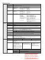
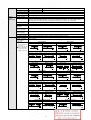
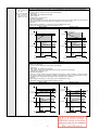
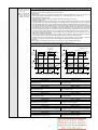
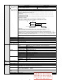
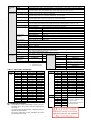
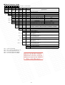
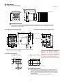
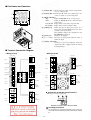
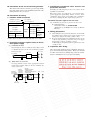


![1127117 - [PROJECT.TOC] - Performance Heating & Plumbing](http://vs1.manualzilla.com/store/data/005895106_1-55e9d6c83dbc31a8ba61d6bb401245cf-150x150.png)