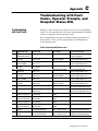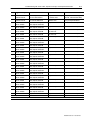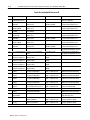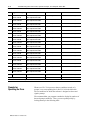
1
3–12
Customize the Wiring
Customize a
Grounded AC System
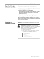
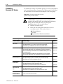
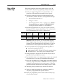
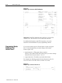
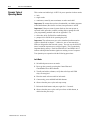
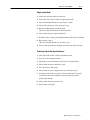
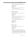
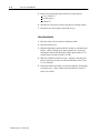
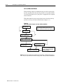
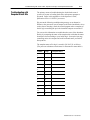
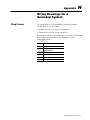
To customize the wiring of I/O module groups 2-5 to suit your application,
refer General Instructions to Customize Your Wiring (page 3), and follow
the instructions below. Instructions and examples are on facing pages.
Important: If using ungrounded ac power,
go back to the previous section.
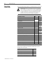
ATTENTION: To guard against unexpected machine
operation with possible injury to personnel and/or machinery
damage, do not modify the wiring of system power
distribution (sheet 1 of 9) except as follows:
1.
2.
Deletion of crowbar relays.
Enter your own wiring in the EMERGENCY STOP BY
zone 01-12 for such switches as:
E-Stop pushbuttons
die block
air pressure for C/B and counterbalance
CUSTOMER
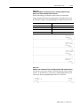
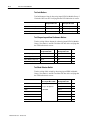
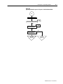
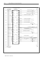
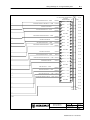
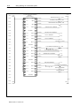
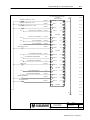
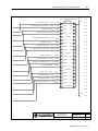
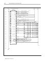
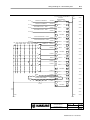
I/O Module Group 2 (sheet 6 of 9)
Grounded AC Power
For this modification
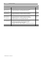
Make these changes
And see
Replace RCLSs
with resolvers
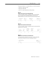
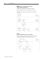
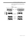
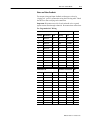
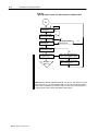
1. Delete the three pairs of limit switches (RLCSs) at input terminals [ 1 ], [ 3 ], and [ 5 ].
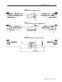
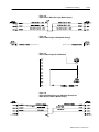
Figure 3.13
Delete Crowbar Relays
Delete Clutch/Brake
Air Pressure Switch
Delete Main Motor
Forward Switch
2. Wire input terminals [ 1 ], [ 3 ], and [ 5 ] to power rail 108L1 (wire high).
3. Write ladder logic to simulate the action of the rotary cam limit switches.
Figure 7.5
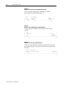
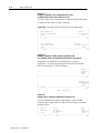
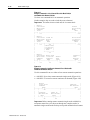
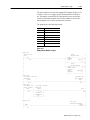
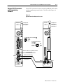
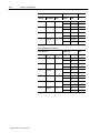
1. Delete wiring crowbar relay feedback to input terminal [25] for chassis A and B.
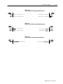
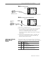
We deleted the wiring (Figure 3.14) and added the label (Reserved, Do Not Use).
Figure 3.14
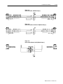
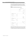
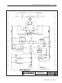
2. Delete Crowbar Relays A and B from the Power Distribution Drawing (sheet 1 of 9)
Figure 3.15
3. See Module Group 5.
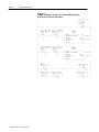
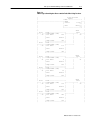
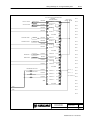
Delete Crowbar Relays and wiring from output terminal 33 for chassis A and B.
We deleted the wiring (Figure 3.24) and added the label (Reserved, Do Not Use).
Figure 3.24
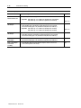
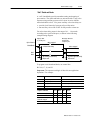
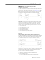
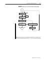
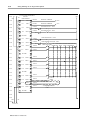
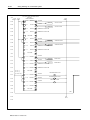
1. Delete the clutch/brake air pressure switch at input terminal [33] for chassis A.
Figure 3.16
2. Wire input terminal [33] of chassis A and B to power rail 108L1 (wire high).
3. Write ladder logic to monitor clutch/brake air pressure.
Figure 4.9
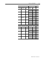
1. Delete the main motor forward switches at input terminal [35] for chassis A and B.
Figure 3.16
2. Wire input terminal [35] to power rail 108L1 (wire high).
3. Write ladder logic to monitor the device that detects forward motion.
Figure 4.13
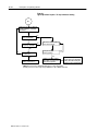
Replace Motion Detector 1. Delete the motion detector switches at input terminal [37] for chassis A and B.
Switch with Ladder
2. Wire input terminal [37] to power rail 108L1 (wire high).
Logic
3. Write ladder logic to simulate the action of the motion detector switch.
Figure 3.16
Seal Relay, C/B Power
Reset and Feedback,
CRM and Feedback
N/A
Publication 65566.5.1 - October 1996
1. No modifications allowed. You must wire these inputs as shown on sheet 1 of 9
for the control system to work correctly.
Figure 4.10