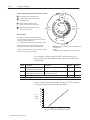
1
–1 Allen-Bradley Omega Series Configurable Press Control System (Cat. No. 6556-SCBK3 and 6556-SCBK3DC) User Manual Important User Information Because of the variety of uses for the products described in this publication, those responsible for the application and use of this control equipment must satisfy themselves that all necessary steps have been taken to assure that each application and use meets all performance and safety requirements, including any applicable laws, regulations, codes and standards. The illustrations, charts, sample programs and layout examples shown in this guide are intended solely for purposes of example. Since there are many variables and requirements associated with any particular installation, Allen-Bradley does not assume responsibility or liability (to include intellectual property liability) for actual use based upon the examples shown in this publication. Allen-Bradley publication SGI-1.1, Safety Guidelines for the Application, Installation, and Maintenance of Solid-State Control (available from your local Allen-Bradley office), describes some important differences between solid-state equipment and electromechanical devices that should be taken into consideration when applying products such as those described in this publication. Reproduction of the contents of this copyrighted publication, in whole or in part, without written permission of Allen-Bradley Company, Inc., is prohibited. Throughout this manual we use notes to make you aware of safety considerations: ! ATTENTION: Identifies information about practices or circumstances that can lead to personal injury or death, property damage or economic loss. Attention statements help you to: • identify a hazard • avoid the hazard • recognize the consequences Important: Identifies information that is critical for successful application and understanding of the product. PanelView and SLC are trademarks of Allen-Bradley Company, Inc. Publication 6556-6.5.8 August 1998 Preface Manual Objectives This manual describes how to apply the 6556-SCBK3 or 6556-SCBK3DC Clutch/Brake (C/B) Control Kit, including Programmable Limit Switch (PLS) and Die Monitor (DM) functions to your mechanical stamping press. The manual helps you install, test, and operate the control. Other Required Publications To complete the installation of this clutch/brake control system, you will need to use these publications, some of which accompany other Rockwell Automation products in the system: To Do This: complete the overall installation use PanelView 600 Operator Interface to set up and operate the system wire the control system understand the non–programmable aspect of your SLC 5/03 processors mount the I/O chassis Qualifications for Applying this Product Use this Publication Omega Series Configurable Press Control System (this manual) Clutch/Brake PanelView 600 Operating Instructions ac or dc Wiring Drawings (6556503 and 6556503DC) Pub # 6556-6.5.11 6556-5.8 6556-2.15 Modular Chassis Install Instructions 6556-6.5.11 RN1 1746-5.8 install the system power supply Power Supply Install Instructions 1746-5.1 install the isolated link coupler Link Coupler Install Instructions with coupler install digital I/O modules I/O Module Install Instructions 1746-5.3 Read This First install the resolver with resolver install the resolver input module with module install the tonnage module (optional) with module install the analog I/O module (optional) with module Only qualified installers should apply this control to a mechanical stamping press. We assume that the installation team includes: • professional stamping press builder or re-builder, knowledgeable in press control and press-control standards • technician, skilled in installing electronic control equipment Recommendation to Help You Install the System The descriptions of operation of this control system and its associated resolver, die monitor (DM) and programmable limit switch (PLS) functions are important to understanding how this system works. We recommend that you review and understand the Overview (chapter 1) before starting to install this system. You may also want to browse through this manual, the wiring drawings, and the PanelView 600 Operating Instructions before starting this project. Publication 6556-6.5.11 – July, 1998 P–2 Terms and Abbreviations You should become familiar with these abbreviated terms. For complete definitions of clutch/brake terms, refer to ANSI B11.1-1988 section 3. Term Definition ACAM anti-repeat RCLS a device designed to limit press operation to a single cycle if the actuating means is held actuated. bottom position the part of the press cycle where the dies are closed BCAM brake monitor RCLS a device designed to prevent the next stroke if stopping time or distance exceeds a preset buttons palm-type pushbutton switches used by an operator for starting and stopping the press clutch/brake valve the main valve that controls the flow of air to the clutch/brake mechanism continuous mode the mode where the control maintains continuous stroking after an operator starts the press DM die monitor a combination of switches and logic used to protect automation machinery and stamping dies from damage if/when a part deviates from its intended path thru a sequence of progressive dies downstroke zone the part of the press cycle when the press travels from near-top zone (through bottom) to the upstroke zone fault detection for valves internal: valve is designed to turn itself off when it faults. grounded ac power ac power distribution where the “L2” side of the ac line is grounded inch mode a mode that lets an operator move the press incrementally by pressing and releasing run-station buttons near top zone the part of the press cycle when the press is at the top of its stroke PLS programmable limit switch a switch, synchronized with the rotary position of a crankshaft, to cycle an output on/off at precise positions RCLS - rotary cam limit switch a switch that rides a rotating cam to provide information on the position of the press crankshaft resolver an electro-mechanical device that precisely monitors the angular position of a rotating shaft run station a press operator’s point of operation that typically contains a pair off pushbuttons to start or stop the press single-stroke mode a mode that allows the operator to run one complete press stroke, usually started at the top SLC small logic controller a Rockwell Automation (Allen-Bradley) programmable controller solenoid valve an on/off electrically-driven valve TCAM takeover RCLS a device designed to allow upstroke without the operator holding the run/inch buttons top stop a command designed to stop the press at the top of its stroke upstroke zone the part of the press cycle when the press travels from the end of downstroke to the near-top position Publication 6556-6.5.11 – August 1998 Overview Quick Start Installing and Wiring Testing C/B Circuits Chapter 1 Chapter Objective . . . . . . . . . . . . . . . . . . . . . . . . . . . . . . . . . . . . . . . . . . Contents of the Kit . . . . . . . . . . . . . . . . . . . . . . . . . . . . . . . . . . . . . . . . . . About This Control System . . . . . . . . . . . . . . . . . . . . . . . . . . . . . . . . . . . Control by Redundant Processors . . . . . . . . . . . . . . . . . . . . . . . . . . . . . . Link Couplers . . . . . . . . . . . . . . . . . . . . . . . . . . . . . . . . . . . . . . . . . . . . . Protected Memory in SLC 5/03 Processors . . . . . . . . . . . . . . . . . . . . . . . Modes of C/B Operation . . . . . . . . . . . . . . . . . . . . . . . . . . . . . . . . . . . . . Functional Block Diagram . . . . . . . . . . . . . . . . . . . . . . . . . . . . . . . . . . . C/B Control Functions . . . . . . . . . . . . . . . . . . . . . . . . . . . . . . . . . . . . . . . Resolvers . . . . . . . . . . . . . . . . . . . . . . . . . . . . . . . . . . . . . . . . . . . . . . . . . Rotary Cam limit Switches . . . . . . . . . . . . . . . . . . . . . . . . . . . . . . . . . . . Panel Switches and Input Switches . . . . . . . . . . . . . . . . . . . . . . . . . . . . . C/B Outputs . . . . . . . . . . . . . . . . . . . . . . . . . . . . . . . . . . . . . . . . . . . . . . . C/B Response Time . . . . . . . . . . . . . . . . . . . . . . . . . . . . . . . . . . . . . . . . . Programmable Limit Switches (PLS) . . . . . . . . . . . . . . . . . . . . . . . . . . . Die Monitor (DM) . . . . . . . . . . . . . . . . . . . . . . . . . . . . . . . . . . . . . . . . . . Tonnage Monintor . . . . . . . . . . . . . . . . . . . . . . . . . . . . . . . . . . . . . . . . . . Related Safety Information . . . . . . . . . . . . . . . . . . . . . . . . . . . . . . . . . . . Specifications of the C/B Control, PLS, and DM . . . . . . . . . . . . . . . . . . 1-1 1-1 1-2 1-3 1-3 1-3 1-4 1-4 1-4 1-5 1-5 1-5 1-6 1-6 1-6 1-7 1-8 1-9 1-10 Chapter 2 Procedure for the Clutch/Brake Control . . . . . . . . . . . . . . . . . . . . . . . . . 2-1 Procedures for Setting Up PLS and DM Channels . . . . . . . . . . . . . . . . . 2-3 Chapter 3 Chapter Objectives . . . . . . . . . . . . . . . . . . . . . . . . . . . . . . . . . . . . . . . . . If Using the DC Version . . . . . . . . . . . . . . . . . . . . . . . . . . . . . . . . . . . . . Check the Hardware . . . . . . . . . . . . . . . . . . . . . . . . . . . . . . . . . . . . . . . . Mount the I/O Chassis . . . . . . . . . . . . . . . . . . . . . . . . . . . . . . . . . . . . . . Install the Power Supply . . . . . . . . . . . . . . . . . . . . . . . . . . . . . . . . . . . . . Install the Isolated Link Couplers . . . . . . . . . . . . . . . . . . . . . . . . . . . . . . Install the SLC Processors and I/O Modules . . . . . . . . . . . . . . . . . . . . . Set Up Rotary Cam Limit Switches . . . . . . . . . . . . . . . . . . . . . . . . . . . . Install C/B Input Switches and Resolver(s) . . . . . . . . . . . . . . . . . . . . . . . Connect Chassis Cables . . . . . . . . . . . . . . . . . . . . . . . . . . . . . . . . . . . . . Wire Your C/B Control . . . . . . . . . . . . . . . . . . . . . . . . . . . . . . . . . . . . . . Wiring Considerations . . . . . . . . . . . . . . . . . . . . . . . . . . . . . . . . . . . . . . 3-1 3-1 3-1 3-1 3-1 3-1 3-2 3-3 3-5 3-5 3-6 3-7 Chapter 4 Chapter Objective . . . . . . . . . . . . . . . . . . . . . . . . . . . . . . . . . . . . . . . . . . 4-1 Testing Circuits and Failure-mode Operation . . . . . . . . . . . . . . . . . . . . 4-1 Publication 6556-6.5.11 – August 1998 P–2 Testing C/B Operation Determining Your DM and PLS Requirements Testing DM and PLS Channels Description of Operating Modes Index Publication 6556-6.5.11 – August 1998 Chapter 5 Chapter Objective . . . . . . . . . . . . . . . . . . . . . . . . . . . . . . . . . . . . . . . . . . Troubleshooting the Setup of Your RCLS Assemblies . . . . . . . . . . . . . . Test the Operating Modes . . . . . . . . . . . . . . . . . . . . . . . . . . . . . . . . . . . . Test the Switches . . . . . . . . . . . . . . . . . . . . . . . . . . . . . . . . . . . . . . . . . . . 5-1 5-1 5-2 5-3 Chapter 6 Chapter Objective . . . . . . . . . . . . . . . . . . . . . . . . . . . . . . . . . . . . . . . . . . Operation of DM Input Modes . . . . . . . . . . . . . . . . . . . . . . . . . . . . . . . . Output Responses for DM Channels . . . . . . . . . . . . . . . . . . . . . . . . . . . . Worksheet for DM Input Channels . . . . . . . . . . . . . . . . . . . . . . . . . . . . . Operation of the PLS . . . . . . . . . . . . . . . . . . . . . . . . . . . . . . . . . . . . . . . . Worksheet for PLS Output Channels . . . . . . . . . . . . . . . . . . . . . . . . . . . . 6-1 6-1 6-3 6-4 6-5 6-6 Chapter 7 Chapter Objectives . . . . . . . . . . . . . . . . . . . . . . . . . . . . . . . . . . . . . . . . . Testing a DM Channel . . . . . . . . . . . . . . . . . . . . . . . . . . . . . . . . . . . . . . . Testing DM Transfer-mode Channels . . . . . . . . . . . . . . . . . . . . . . . . . . . Testing the Resolver Input . . . . . . . . . . . . . . . . . . . . . . . . . . . . . . . . . . . . Testing a PLS Channel . . . . . . . . . . . . . . . . . . . . . . . . . . . . . . . . . . . . . . 7-1 7-1 7-2 7-3 7-3 Appendix A Clutch/Brake Operating Modes . . . . . . . . . . . . . . . . . . . . . . . . . . . . . . . . A-1 Index A-Z . . . . . . . . . . . . . . . . . . . . . . . . . . . . . . . . . . . . . . . . . . . . . . . . . . . . . I-1 Chapter Objective The purpose of this chapter is to acquaint you with your Allen-Bradley Clutch/Brake Control (cat. no. 6556-SCBK3 or -SCBK3DC). Topics include: • • • • • • • • • • • • • • • • • • Contents of the Kit Contents of the kit About this control system Control by redundant processors Link couplers Protected memory in SLC-5/03 processors Modes of C/B operation C/B control functions Functional block diagram Resolvers Rotary cam limit switches Panel switches and input switches C/B Outputs C/B Response time Programmable Limit Switches (PLS) Die Monitor (DM) Tonnage monitoring Related safety documentation Specifications of the C/B control, PLS, and DM 1 2 3 3 3 4 4 4 5 5 5 6 6 6 7 8 9 10 Clutch/brake control kit (cat. no. 6556-SCBK3 or -SCBK3DC) includes: Hardware Included SLC-5/03 Link Coupler (DH-45) Power Supply 7-slot I/O Chassis 10-slot I/O Chassis Input Module Input Module Output Module Relay Output Module Relays (2) (2) (2) (1) (1) (4) (1) (2) (2) (4) for -SCBK3 for -SCBK3DC Hardware That You Provide 1747-L532 1747-AIC 1746-P2 1746-A7 1746-A10 1746-IA16 (ac) 1746-ITV16 1746-OA16 1746-OX8 700-P400A1 1747-L532 1747-AIC 1746-P2 1746-A7 1746-A10 1746-IB16 (dc) 1746-ITV16 1746-OB16 1746-OX8 700DC-F310Z24 Input Switches and Run Stations (application dependent) Rotary Cam Limit Switche (1, if used) Resolver (minimum of 1) Resolver Input Module (minimum of 1) Solenoid Valves (4) with Internal Fault Detection Operator Interface (1) PanelView 600 (6556-SPV600) Tonnage Module (optional, 2 max) Analog I/O Module (1, optional) Important: The purchase of this kit includes the license to use this control on one stamping press. Publication 6556-6.5.11 August 1998 1–2 Overview About This Control System This is a pre-programmed SLC-based control system that provides for: • Clutch/brake Control – for controlling a mechanical stamping press ATTENTION: The clutch/brake control system is designed for use only with mechanical stamping presses having a part-revolution friction clutch and/or brake. Applying this control to any other type of press could result in personal injury and/or damage to equipment. • Die Monitoring – permissives designed to monitor the proper progression of the part and to prevent the die from closing upon detecting a part mis-alignment or mal-function of part transfers • Programmable Limit Switches – that you use to turn outputs on or off at precise crankshaft positions synchronized with crankshaft rotation monitored by a resolver • Tonnage Monitoring – optional modules to accept strain-gage inputs to monitor the pressure generated on the stamped part • Other features – diagnostics for SLC-based troubleshooting – recipe management for storing up to 20 setups – production monitor for indicating progress during a production run – lube for automatic or manual lubrication of the press This SLC-based control system consists of: • • • • two SLC 5/03 processors with factory-installed control software two I/O chassis with input and output modules two link couplers for inter-processor communication PanelView Operator Interface Terminal PanelView terminal lets you – enter setpoints – observe operation, and – store setup files for use later I/O chassis holds modules that process I/O signals. LC A resolver provides precise rotational inputs to monitor press stroke. Power Supply Power Supply Nj Multiple switches provide inputs to monitor correct part movement synchronized with the press stroke. Nj Link Coupler to provide for communication between processors. Publication 6556-6.5.11 August 1998 SLC processor with pre-programmed software monitors inputs, and controls the clutch/brake mechanism and other press-control functions. Overview 1–3 Control by Redundant Processors This clutch/brake control uses two independent SLC 5/03 processors, one in chassis A and the other in chassis B. Both processors monitor all clutch/brake I/O and exchange information about machine status. They are linked by hardwired I/O and a pair of Link Couplers (1747-AIC), so that if one processor detects a condition different from that detected by the other, its control logic is designed to declare a fault and turn off all outputs to press valves. The other processor is designed to follow suit. Link Couplers Link couplers (cat. no. 1747-AIC) provide communication between processors in chassis A and B. They also provide communication between the PanelView 600 Operator Interface and both processors. For additional information, refer to wiring drawings, sheet 4, and the instructions that accompanied the link couplers. Protected Memory in SLC 5/03 Processors The logic of this control is pre-programmed and burned into processor memory at the factory. It cannot be changed except by return to Allen-Bradley. You cannot program these clutch/brake processors. Publication 6556-6.5.11 August 1998 1–4 Overview Modes of C/B Operation An operator can select the mode of clutch/brake operation with a selector switch located on a control panel. In accordance with ANSI B11.1 Section 4.12.4.1, the selection of operating mode must be lockable. This Mode: Off Lets the Operator: Disable operation of the clutch/brake control when the press is not in operation. Inch Jog the press through through successive parts of the cycle by pressing and releasing the pair of run/inch buttons. If the buttons are held, the press will stop at the top of its stroke. Single-stroke Run the press through one complete cycle by holding both run/inch buttons until completion of the down stroke. Continuous Run the press continuously until stopped by a stop-on-top command, or until a fault is detected. To start the press, you press the ARM CONTINUOUS switch and then press the pair of run/inch buttons within five seconds. C/B Control Functions Clutch/brake control functions are summarized in the following table. Control Function: Operating Mode: Stop-on-top (cycle stop) Interrupted stroke Continuous Single or Continuous Lets the operator stop the press by releasing a run/inch button during downstroke. Anti-tie-down All Prevents the press from starting a new stroke if the control detects that an operator has tied down the run/inch buttons. After run/inch buttons are released, the operator must press both buttons at the same time. Anti-repeat Single-stroke or Inch Limits press operation to a single stroke, even if the operator continues to press both run/inch buttons. The operator must release and press them again to start the next stroke. Motion detector Single or Continuous Brake Monitor All Functional Block Diagram Description: Lets the operator stop the press at top of stroke Detects press motion from a hardware or software input. Prevents restarting the press when the control detects an over-travel condition. The functional block diagram in shows the relationships between mechanical components of a stamping press and the C/B control. Run Station 1 pair of buttons for run and inch SLC Processor in Chassis A SLC Processor in Chassis B Signals to/from Main Solenoid Valves Stroke Position Input Clutch/Brake Assembly Flywheel Stroke Position Input Air Supply Main Solenoid Valves Air to clutch Resolver to Monitor Stroke Position Press Crankshaft RCLS or Resolver to Monitor Stroke Position Crankshaft at Top Position Crankshaft at Bottom Position Publication 6556-6.5.11 August 1998 Overview Resolvers 1–5 The control system requires at least one resolver and resolver input module to precisely monitor the crankshaft’s rotational position for clutch/brake control and PLS operation. We recommend the following, purchased separately: • resolver: Rockwell Automation 846–SJDN1CG–R3 • resolver input module: Helm HM571–RES Rotary Cam Limit Switches You may use a rotary cam limit switche as the redundant input to monitor the crankshaft’s position. We recommend Allen-Bradley Cat. No. 803-P775 that you purchase separately. Panel Switches and Input Switches The clutch/brake control requires the panel and input switches listed below. You purchase them separately. Device Symbol Purpose Type Allen-Bradley Type Qty Lets press operators start the press Assures 2-hand operation Note: Position run/inch buttons at least 24” apart., and the run station in accordance with ANSI B11.1 appendix A. Momentary pushbuttons dual contact normally closed (N.C.) and normally open (N.O.) (2) Articulated Palm Buttons 800P-F2CA 1 pair Stop on Top Stops press at top during continuous stroking No effect in single mode Momentary pushbutton single N.C. contact Yellow Mushroomhead 800T-D9B 1 E-Stop Stops the press immediately Note: Wire switches in series as needed. Momentary pushbutton single N.C. contact Jumbo Mushroomhead 800T-FXP16RA5 Mode Select Lets you select the operating mode: Off Inch Single Continuous Rotary, 4-position key lockable 800T-N61KF4C 1 Arm Continuous Lets you begin a timed interval within which to start continuous mode. Momentary pushbutton single N.O. contact Black Momentary Pushbutton 800T-A2A 1 Main Motor Forward Interlock Monitors whether motor-forward starter is engaged. If not, it opens to prevent running the press in single or continuous mode. N.O. auxiliary contact for forward motor starter Motor Starter Auxiliary Contact 595-A 2 Air Pressure Monitors Clutch/Brake air pressure. Note: Switch must be ON to engage the clutch. N.O. single throw from pressure switch Pressure Switch 836-C8JX321 1 Motion Detector Interlock Detects if motion is stopped in single or continuous mode. N.O. single contact N/A 2 Control Reset Lets you manually reset power to valve solenoids at power up or after an E-stop. Momentary pushbutton single N.O. contact 800T-A2A 1 Clutch/Brake Power Reset Lets you manually reset clutch power on power up or after E-stop. Momentary pushbutton triple contact 1 N.O. and 2 N.C. 800T-A2B 1 Palm Buttons for Run Station Left Right 1 or more Publication 6556-6.5.11 August 1998 1–6 Overview C/B Outputs The clutch/brake control has two pairs of outputs from each I/O chassis (chassis A and B) for your clutch/brake valves. The control is designed to operate with valves that have internal fault detection. There are no inputs for valve-stem feedback. C/B Response Time The worst case time required for the clutch/brake control to respond to a change of input depends on the sum of these response times: Device: Delay (ms): Input Module 1746-IA16 response time 45 Processor scan of C/B code (2k words) 10 Output Module 1746-OX8 switching time 10 Total worst-case response time 65 The number of degrees that the shaft continues to rotate beyond the moment at which the input changes depends on the speed of rotation. The greater the speed (strokes per minute), the further the shaft rotates before a command from the control is applied. We graphed the degrees of shaft rotation vs press speed for a response time of 65 ms. SPM 100 90 80 70 60 50 40 30 20 10 0 0 65 ms 10 20 30 40 Degrees of Shaft Rotation 50 Important: When estimating the braking distance in degrees of rotation, you must add the rotation occurring during system response time to the specified downstroke braking distance. (For example, at 100 SPM, the shaft rotates 39o during a 65 ms system response time plus the braking distance.) Publication 6556-6.5.11 August 1998 Overview Programmable Limit Switch (PLS) 1–7 The Allen-Bradley Programmable Limit Switch is factory-programmed ladder logic that lets you time or sequence outputs according to precise and repeatable positions of a crankshaft. Crankshaft positions are monitored by a resolver. You can use PLS outputs to integrate auxiliary press machinery such as lifters, grippers blow-off valves, and inter-press automation into your stamping press control system. (See chapter 3 for wiring PLS outputs.) How a PLS Channel Works Using the PanelView 600 Operator Interface, you preset the rotational position (preset angle) at which you want the PLS output to turn ON. You also select how you want the PLS output to turn OFF: by preset angle or preset time. The output module in chassis A, slot 4 controls the outputs to your application. 0o Near-top Zone Angular preset to turn output ON Down stroke 90o Zone Up 270o stroke Zone Angular or time preset to turn output OFF Bottom 180o Then, you can select your application-specific PLS output to trigger: • part movement between presses in a transfer line • die automation devices such as grippers and lifters • monitoring correct part movement with a DM track function Die Monitoring (DM) Allen-Bradley Die/Automation Monitoring is factory-programmed ladder logic designed to let you monitor a variety of conditions synchronized with the rotation of a stamping press crankshaft. The logic is designed to detect the absence, mis-alignment, or unwanted presence of material moving through an automated stamping process. Crankshaft positions are monitored by a resolver. (See chapter 3 for wiring DM inputs.) You enter setups with the PanelView PV600 Operator Interface. The software and associated hardware: • monitor a variety of logical inputs to detect deviant conditions • set a fault upon detection of a deviant condition You select whether the fault automatically initiates a warning, stop-on-top, stop-now condition, or whether the fault is ignored. Publication 6556-6.5.11 August 1998 1–8 Overview How a DM Channel Works You select one of several operational modes for a DM input, such as: • • • • cyclic in-position transfer static As long as the logic detects expected conditions, no action is taken. When the logic detects a deviant condition, it sets a fault. For example, in cyclic mode an input switch is expected to close within a preset zone of rotation that we call a window. Cyclic Mode Transition Diagram a b Expected Transition Occurs Within Window Input is NOT ALLOWED When Sensor: Sensor turns ON then OFF within window a-b 1. stays ON beyond the window (Pulse-type signal) Which Results in a Fault SIGNAL Sent After: window goes OFF 2. turns ON outside the window sensor turns ON 3. remains OFF for the cycle next window goes ON You can use a DM input to monitor: • an individual station for a part in correct position (in-position mode) • a sequence of stations for the progression of a part (transfer mode) The software provides up to 16 DM selectable input channels. You connect DM inputs to the 1746-ITV input module in chassis A, slot 6. Tonnage Monitoring The optional tonnage monitor lets you view either two or four tonnage points upon each closure of the die. The PanelView 600 Operator Interface displays a set of tonnage screens that lets you: • set up and calibrate tonnage channels • view absolute tonnage and deviation from benchmark tonnage with each closure of the die • set alarms to indicate when detected tonnage exceeds upper or lower limits We recommend the following tonnage monitor, purchased separately: • tonnage input module: Helm HM604–TSM • tonnage sensors and secondary calibration standard, also from Helm Publication 6556-6.5.11 August 1998 Overview Related Safety Information 1–9 You are responsible for the safety of the installed press control, and for meeting all applicable laws, codes, and safety requirements. This control deals only with electrical control portions of the C/B mechanism. ATTENTION: The installer of this control must follow ANSI B11.1 regarding mechanical power presses, OSHA 1910.217, and other applicable standards pertaining to safety recommendations related to: machine construction general electrical machine guarding point-of-operation guards, light-curtain gates, 2-hand switches In addition to local codes and laws, you are responsible for the safety recommendations detailed in all applicable codes and standards including: • OSHA Regulations, Title 29-Labor, Chapter XVII, Section 1910.217, Mechanical Power Presses • ANSI B11.1, American National Standard for Machine Tools, Mechanical Power Presses, Construction, Care, and Use (available from American National Standards Institute 1430 Broadway NY, NY 10018-3363) • NFPA No. 79, Electrical Standard for Metalworking Machine Tools • CAN/CSA-Z142-M90 Code for Punch Press and Brake Press Operation: Health, Safety, and Guarding Requirements (Canadian Standards Assoc. 178 Rexdale Blvd. Rexdale (Toronto) Ontario Canada M9W 1R3) Also refer to Important User Information inside the front cover. Publication 6556-6.5.11 August 1998 1–10 Overview Specifications for the Clutch/Brake Control Type of processors pair of SLC 5/03 processors (preprogrammed, non-programmable) Type of power grounded ac (6556-SCBK3) dc (6556-SCBK3DC) C/B mode selections off inch single stroke continuous Valve outputs two clutch/brake valves Type of valves internal fault detection Position monitoring inputs at least one resolver input, and one additional resolver, or one additional rotary cam limit switch assembly Response time 65 ms worst case from switched input to turned-OFF output Specifications for Programmable Limit Switches and Die Monitoring Programmable Limit Switches Number of PLS channels 8 Channel input preset range 0-359o Channel output response turn OFF based on choice of 0-359o or time (ms) Machine inputs top stop E-stop run station (1) mode select (rotary switch) clutch/brake air pressure motor forward interlock motion detector interelock arm for continuous on demand control reset C/B power reset Environmental conditions Operating Temperature 0 to 60oC (32 to 140oF) Storage Temperature –40 to 85oC (–40 to 185oF) Relative Humidity 5 to 95% (without condensation) Designed to comply with ANSI – B11.1 OSHA – 1910.217 CSA – CAN/CSA-Z142-M90 NFPA No. 79 Die Monitoring Number of DM channels Operating Modes Output responses Publication 6556-6.5.11 August 1998 16 cyclic in-position transfer static warning stop on top stop now ignore Use this chapter as an abbreviated procedure for getting setting up the clutch/brake control, PLS and/or DM functions; or as an overview if you need more information. Procedure for Clutch/Brake Control 1. Verify That You have All of the Hardware Shipped in the Kit Hardware Included • • • • • • • • • SLC-5/03 Link Coupler (DH-45) Power Supply 7-slot I/O Chassis B 10-slot I/O chassis A Input Module Output Module Relay Output Module Relays (2) (2) (2) (1) (4) (2) (2) (4) this manual chapter 1 for -SCBK3 for -SCBK3DC Hardware That You Provide 1747-L532 1747-AIC 1746-P2 1746-A7 1746-A10 1746-IA16 (ac) 1746-OA16 1746-OX8 700-P400A1 1747-L532 1747-AIC 1746-P2 1746-A7 1746-A10 1746-IB16 (dc) 1746-OB16 1746-OX8 700DC-F310Z24 • Input Switches & Run Station (Application Dependent) • Resolver and resolver input module (minimum of one set) • Rotary Cam Limit Switch assembly (one set if used) • Solenoid Valves (4) with Internal Fault Detection • PanelView 600 Operator Interface (6556-SPV600) 2. Mount the I/O Chassis publication 1746-5.8 3. Install the Power Supply publication 1746-5.1 4. Install the Link Coupler instructions in LC box 5. Install SLC Processors and I/O Modules for Chassis A and B publication 1747-6.2 Important: You must identify Processor A (by its label), and install it in the 10-slot chassis A. Installing the wrong processor in chassis A or B will result in a processor fault at power up. Chassis B (7-slot) Slot Chassis A (10-slot) 0 SLC 5/03 Processor A 1747-L532 SLC 5/03 Processor B 1747-L532 1 Input Module 1746-IA16 (ac) or 1746-IB16 (dc) Input Module 1746-IA16 (ac) or 1746-IB16 (dc) 2 Input Module 1746-IA16 (ac) or 1746-IB16 (dc) Input Module 1746-IA16 (ac) or 1746-IB16 (dc) 3 Resolver Input Module (required) Resolver Input Module (optional) 4 Output Module 1746-OA16 Output Module 1746-OB16 5 Isolated Relay Output Module 1746-OX8 6 7 8 9 Input Module for Die Monitor 1746-ITV16 spare optional Tonnage Module Helm HM579-TSM optional Tonnage Module Helm HM579-TSM Isolated Relay Output Module 1746-OX8 ooptional tional I/O Module o ul 1746-N 1746-NIO4V 4 for: o – auto count counterbalance balanc – variable-speed a iabl -s press ss drive i – shut-height adjustment Publication 6556-6.5.11 August 1998 2–2 Quick Start 6. Description: run station, inch/run E-stop mode selection top stop arm continuous E-stop reset C/B power reset main motor forward motion detector air pressure resolvers or resolver & RCLS 7. Type: al button palm rotary, key-lockable us button push N. N.O.. singl single contact See chapter 1. During downstroke, BCAM must be On. During upstroke, TCAM must be On and BCAM must be Off. During upstroke, ACAM must cycle from On to Off to On while TCAM is On. Near top, BCAM and TCAM must be Off while ACAM remains On C D this manual chapter 1 Set Up (if used) or Simulate Rotary Cam Limit Switches 0o Set Up or Simulate Rotary Cam Limit Switches as Follows: A B n/a Install C/B Input Switches and the Resolver (You wire them in step 9.) Near-top Zone D A TCAM ACAM 270o Up stroke Zone BCAM C Down stroke Zone 90o Other Conditions: The software is designed to fault if/when it detects: a. ACAM, BCAM, and TCAM are OFF all at the same time. b. BCAM is On when ACAM is Off. B c. ACAM does not cycle while TCAM is On during upstroke. Bottom ACAM should remain On for the entire stroke except for an On/Off/On cycle while TCAM is On during upstroke. 180o Important: See press manufacturer’s recommendations Dual sets of contacts need not cycle at same moment. for on/off settings of ACAM, BCAM, and TCAM switches. An offset of up to 1 second is acceptable. 8. this manual chapter 3 Connect the Cables You must make the cable that connects the two link couplers. See the Installation Instructions that accompanied the link coupler for the terminations. The cable uses a pair of 6-pin phoenix connectors. Use this cable: to connect: that you make between link couplers in chassis A and B 1747-C11 Link coupler to the SLC processor 9. notes: see coupler installation instructions came with the link coupler, two required Wire the I/O Modules, RCLS, and Input Switches For wiring instructions, refer to chapter 3 and Wiring Drawings (publication 6556-2.15) Publication 6556-6.5.11 August 1998 chapter 3 and Wiring Dwgs. Quick Start 10. 2–3 chapter 4 Test Clutch/Brake Circuits ATTENTION: Be sure that all C/B hardware is installed before starting this step. 11. chapters 5 Test Clutch/Brake Operation Procedures for Setting Up PLS and DM Channels 1. Familiarize yourself with PLS and DM operation. 2. If using DM, determine your DM requirements. Chapters 1 & 6 Chapter 6 Determine the quantity of DM input channels, their modes, types of input switches, and their locations. We provide worksheet A for your convenience. Wire DM input switches to the 1746-ITV16 input module in chassis A, slot 6. 3. If using PLS, determine your PLS requirements. Chapter 6 Determine the quantity of PLS channels, turn-ON presets, and turn-OFF angle or time. We provide worksheet B for your convenience. Wire PLS outputs from the 16-point output module in chassis A, slot 4, pts 8-15. 4. Use the PanelView 600 Operator Interface to set up system configuration, DM and PLS channels, the resolver, passwords, and variable-speed compensation Operating Instr. 6556-5.8 Refer to the referenced publication for System, DM, and PLS setup procedures. They include: – System Configuration – Active PLS/DM setups, on line – Recipe PLS/DM setups, offline – System Monitoring 5. Test DM and PLS channels. Chapter 7 Use procedures in chapter 7 and screens described in the PanelView 600 Operating Instructions to test: – DM and PLS channels – resolver inputs – transfer-mode channels Publication 6556-6.5.11 August 1998 2–4 Quick Start Notes: Publication 6556-6.5.11 August 1998 Chapter Objective In this chapter, we help you install the C/B control with these steps: • • • • • • • • • • • If Using the DC Version if using the dc version check hardware mount the I/O chassis install the power supply install the isolated link coupler install SLC processors and I/O modules set up rotary cam limit switches install C/B input switches and resolver(s) connect chassis cables wire your C/B control wiring considerations 1 1 1 1 1 2 3 5 5 6 7 We provide wiring drawings (publication 6556-2.15) for two versions: grounded ac (drawing set 6556503) and dc (drawing set 6556503DC). The dc version has these changes in respect to the ac version: • replace input module 1746-IA16 with 1746-IB16 in slots 1 and 2 • replace output module 1746-OA16 with 1746-OB16 in slot 4 • replace wiring drawing set 6556503 with 6556503DC Check Hardware To check the contents of the kit, refer to Contents of Kit in chapter 1. If items are missing, contact your local salesperson or distributor. Mount the I/O Chassis To mount the 7-slot and 10-slot I/O chassis (Cat. No. 1746-A7 and 1746-A10), refer to publication 1746-5.8, SLC 500 Modular Chassis Installation Instructions. Look for this publication in the product box. Install the Power Supply To install the power supply (Cat. No. 1746-P2), refer to publication 1746-5.1, SLC 500 Power Supplies Installation Instructions. Look for this publication in the box that contained the power supply. The power supply slides into card guides on the left side of the I/O chassis. Install the Isolated Link Coupler To install the link coupler (Cat. No. 1747-AIC), refer to publication Installation Instructions for the SLC500 Isolated Link Coupler shipped with it. Mount the coupler. adjacent to the power supply on the panel holding the I/O chassis. Keep the instruction sheet handy because you will use it to fabricate and connect cables. Publication 6556-6.5.11 August 1998 3–2 Installing and Wiring Install SLC Processors and I/O Modules Install the SLC processors and I/O modules in designated slots of each I/O chassis A and B. Important: You must insert the SLC processor labeled “A” into the 10-slot chassis A, and the processor labeled “B” into the 7-slot chassis B. If reversed, the processors will fault at power up. Self-locking tabs secure the module in the chassis. Door panel label identifies terminal block connections. Removable barrier-type terminal block is color coded to the module for quick identification. Chassis A Slot Description of Module Description of Module 0 Processor A 1747-L532 SLC-5/03 5 Isolated Relay Output Module 1746-OX8 1 Input Module 1746-IA16 (ac) or 1746-IB16 (dc) 6 Input Module 1746-ITV16 2 Input Module 1746-IA16 (ac) or 1746-IB16 (dc) 7 Tonnage Module (optional) Helm HM579-TSM 3 Resolver Input Module (Helm HM571-RES) 8 Tonnage Module (optional) Helm HM579-TSM 4 Output Module 1746-OA16 or 1746-OB16 (dc) 9 Spare Slot 0 Slot 1 SLC 5/03 IA16 1747-AIC Link Coupler Publication 6556-6.5.11 August 1998 Slot 1746-P2 Power Supply Slot 2 IA16 Slot 3 Resolver Resolver Input Module Slot 4 OA16 Slot 5 OX8 Slot 6 ITV16 Slot 7 Slot 8 Slot 9 Tonnage Tonnage Spare Spare Installing and Wiring 3–3 Chassis B Slot Description of Module Slot Description of Module 0 Processor B 1747-L532 SLC-5/03 4 Output Module 1746-OA16 or 1746-OB16 1 Input Module 1746-IA16 (ac) or 1746-IB16 (dc) 5 Isolated Relay Output Module 1746-OX8 2 Input Module 1746-IA16 (ac) or 1746-IB16 (dc) 6 I/O Module 1746-NIO4I (optional) 3 Resolver Input Module (optional) Helm HM571-RES Slot 0 Slot 1 SLC 5/03 IA16 1747-AIC Link Coupler Set Up Rotary Cam Limit Switches 1746-P2 Power Supply Slot 2 IA16 Slot 3 Resolver Slot 4 OA16 Slot 5 OX8 Slot 6 NIO4I Optional Resolver Input Module To set up (or simulate with a resolver) rotary cam limit switches, set up the cam angles for each switch assembly as described below and according to the press manufacturer’s installation instructions. Important: Mount these assemblies on opposite ends of the crankshaft so a mismatch (fault) will occur if the crankshaft breaks. • brake-monitor (BCAM) contacts close at a point that lets the system detect an increase in braking distance • take-over (TCAM) contacts close at bottom to let the press complete a stroke, and open during upstroke to let the press stop at the top • anti-repeat (ACAM) contacts limit press operation to a single stroke in single-stroke mode This Cam: In this Mode: With these Conditions: Provides a Signal That: Anti-Repeat (ACAM) Inch or Single stroke Cams open and close in upstroke Prevents a second stroke in these modes Take-over (TCAM) Inch or Single stroke Cams open in near-top zone Turns OFF triac outputs for stopping the press at top of stroke (stop-on-top) Continuous Cams open in near-top zone after stop-on-top command Single stroke or Continuous Cams close near bottom just when (or before) BCAM opens Lets the press complete a single stroke or run continuously after run buttons are released When press stops in downstroke beyond BCAM closure Indicates that braking distance is excessive. Turns OFF solenoid outputs to prevent restart. Brake-monitor Single Stroke (BCAM) or Continuous Publication 6556-6.5.11 August 1998 3–4 Installing and Wiring 0o Set Up or Simulate Rotary Cam Limit Switches as Follows: A During downstroke, BCAM must be On. B During upstroke, TCAM must be On and BCAM must be Off. C During upstroke, ACAM must cycle from On to Off to On while TCAM is On. D Near top, BCAM and TCAM must be Off while ACAM remains On. Near-top Zone D A TCAM ACAM 270o Up stroke Zone BCAM Down stroke Zone C 90o Other Conditions: The software is designed to fault if/when it detects: a. ACAM, BCAM, and TCAM are OFF all at the same time. b. BCAM is On when ACAM is Off. c. ACAM does not cycle while TCAM is On during upstroke. ACAM should remain On for the entire stroke except for an On/Off/On cycle while TCAM is On during upstroke. The dual sets of contacts need not cycle at the same moment. An offset of up to 1 second is acceptable. B Bottom 180o Important: See press manufacturer’s recommendations for: * Near-top Zone * Bottom * On/Off settings of ACAM, BCAM, and TCAM switches As an example, we show typical ON/OFF settings for rotary cam limit switches in the following table where you can write down your initial settings. This RCLS: Turns ON at a position: Turns OFF at a position: Typical ON OFF: BCAM • near top, beyond which the software detects a faulty brake • when overlapped by TCAM in ON position 10o 190o TCAM • near bottom • when or before BCAM turns OFF • that lets the press stop correctly on top • before BCAM turns ON 170o 350o ACAM • Remains ON for entire stroke except for an Off span during upstroke (see graph) 1 Your 1 ON OFF: 290o 250o Important: To determine exact settings, refer to recommendations provided by the press manufacturer. Set the ACAM off span to the number of degrees (00 - 900) according to the speed of the press (0-200 strokes per minute). 200 180 160 Press Speed (SPM) 140 120 100 80 60 40 20 0 90 0 30 0 60 0 OFF Span of Anti-repeat Contacts During Up Stroke Publication 6556-6.5.11 August 1998 Installing and Wiring Install C/B Input Switches and Resolver(s) 3–5 Verify that your press has the following switches, required inputs to your clutch/brake control. Refer to chapter 1 for switch specifications. Description: Type: run station, inch/run E-stop mode selection top stop arm continuous E-stop reset C/B power reset main motor forward motion detector air pressure position monitor palm al button rotary, key-lockable push us button N.O.. singl single contact N. two resolvers, or one resolver and one RCLS assembly Follow manufacturer recommendations when installing the resolver(s). Mount position monitors at opposite ends of the crank-shaft axis. If using: Connect them as follows: a pair of resolvers resolver input modules in chassis A and B one resolver and one RCLS assembly resolver to chassis A, RCLS assembly to chassis B Connect Chassis Cables Connect cables as shown. You must make the cable that connects between the two link couplers. See the Installation Instructions that accompanied the link coupler for the terminations. The cable uses a pair of 6-pin phoenix connectors. Use cable: to connect: notes: 1747-C11 1747-C20 that you make came with link coupler, 2 required came with PanelView 600 see coupler installation instructions Link coupler to the SLC processor PanelView 600 to Link Coupler between link couplers in chassis A and B PS To PanelView 600 1747-C20 1747-C11 cable that you make Chassis A Link Cplr PS 1747-C11 Chassis B Link Cplr Publication 6556-6.5.11 August 1998 3–6 Installing and Wiring Wire Your C/B Control We provide wiring drawings (publication 6556-2.15) for the ac (6556503) and dc (6556503DC) versions of this control. Wire your I/O modules and ac or dc power distribution according to those drawings. Inputs and outputs by I/O module and chassis slot are as follows: For In I/O Chassis See Sheet Power distribution n/a 1 of 14 Cabling for Link Coupler and Processor A and B 4 and 5 of 14 Inputs to 1746-IA16 (1746-IB16) • CRM relay • main motor forward, reverse • C/B mode select • Run/Inch buttons • clutch valve 1 feedback • top stop • arm continuous • fault reset • seal relay • C/B air pressure • main motor start, stop, and reverse (feedback) • ACAM, BCAM, TCAM (chassis B, only if used) A and B slot 1 6 of 14 Inputs to 1746-IA16 (1746-IB16) for I/O cross-checking • feedback from various relays • feedback from RCLS • heartbeat A and B slot 2 7 of 14 Helm HM571-RES resolver input module(s) (required for chassis A, optional for chassis B) 1746-OA16 terminals 0-7 for I/O cross-checking • seal relay • BCD mode • ACAM, BCAM, TCAM • clutch output ON • heartbeat 1746-OA16 pts 8-15 for PLS outputs 1746-OA16 pts 8-9 for optional counterbalance outputs slot 3 8 of 14 A and B slot 4 9 of 14 1746-OX8 Outputs • clutch valve outputs and feedback • PLC OK relay and feedback • main motor forward/reverse outputs • indicator outputs A and B slot 5 10 of 14 1746-ITV16 for DM Inputs 1746-NIO4V optional I/O module for counterbalance pressure, shut height position, and variable-speed drive chassis A, slot 6 chassis B, slot 6 11 of 14 Helm HM604-TSM tonnage module (optional) chassis A, slots 7, 8 chassis A, slot 9 12 and 13 of 14 14 of 14 Spare chassis A, only chassis B, only Wire power supplies and other electrical devices according to instructions that accompanied them. Publication 6556-6.5.11 August 1998 Installing and Wiring Wiring Considerations 3–7 DM Inputs Wire die monitor (DM) inputs to the 1746-ITV16 input module in chassis A, slot 6. This module sources current (the load is a sink). Connect 2-wire or 3-wire input switches as follows: Sourcing (sink load) IN 0 –DC IN 1 VDC +DC PLS Outputs Wire PLS outputs to a 1746-OW16 relay-contact output module in chassis A, slot 4, terminals 8-15 as follows: Relay Output VDC OUT 0 +DC (L1 for ac) CR OUT 1 Last OUT –DC (L2 for ac) I/O for Automatic Counterbalance and Variable-speed Press Drive and Shut-height Adjustment Wire these optional features to the 1746-NIO4V module in chassis B, slot 6. Wire its I/O as shown above. Module characteristics include: # Inputs: Input Specs: # Outputs: 2 0 to +10 V dc –10 to +10V dc @ –20 to +20 mA @ 16-bit resolution "16,384 counts 60 ms response 10Hz input filter 2 Output Range 0 to +10V dc 14-bit resolution Publication 6556-6.5.11 August 1998 3–8 Installing and Wiring Notes: Publication 6556-6.5.11 August 1998 C/B Circuit Testing Chapter Objective Once you have completed the installation of your clutch/brake control and wired your I/O devices, use this chapter to check circuit wiring. ATTENTION: Before starting this chapter, be sure that: • all clutch/brake control hardware is installed • clutch/brake wiring is complete • the control is in compliance with all applicable standards Otherwise, personal injury or property damage could result. Testing Circuits and Failure-mode Operation This section describes the following tests: • • • • • • • • • • PLC OK (failure mode) CRM Relay Seal Relay (circuit) Seal Relay (failure mode) Run/inch Buttons Stop-on-top Button Arm Continuous Button Mode Selector Switch Rotary Cam Limit Switches Resolver(s) and Resolver Input Module(s) 1 2 2 3 3 4 4 4 4 4 PLC OK Test (failure mode) This test verifies the correct failure-mode operation of the PLC OK relay for chassis A. You will repeat this procedure for chassis B. 1. With power off, jumper the wired contacts of PLC OK relay (1010CR). 2. Power up. 3. Press the C/B Control Reset button to energize the CRM relay. 4. Press (and momentarily hold) the C/B Power Reset button. 5. Verify that: – the PLC OK relay is NOT energized (red plunger is not recessed) – “PLC OK Check Failed” prompt is displayed on PanelView screen 6. Shut off system power. 7. Remove the jumper. 8. Repeat steps 1-7 for chassis B (PLC OK relay 1033CR). Publication 6556-6.5.11 August 1998 4–2 C/B Circuit Testing CRM Relay Test (circuit) This test verifies that pressing the E-stop button will de-energize the seal and CRM relays. 1. Power up. 2. Visually and with a voltmeter, verify that: – CRMA relay is not energized – outputs to all press valves are Off. 3. Reset the E-Stop circuit by pressing the Control Reset button. 4. Visually and with a voltmeter, verify that: – CRM relay is energized – outputs to all press valves are Off 5. Reset control power by pressing the C/B Power Reset button. 6. With a voltmeter, verify that power rails to C/B outputs are energized. 7. Press the E-Stop button. 8. Visually and with a voltmeter, verify that seal relay and CRM relay are de-energized. Seal Relay Test (circuit) This test verifies that when the seal relay is off, press valves are off; and when the seal relay is on, outputs to press valves are energized. 1. Power up (if not already powered up). 2. Reset the E-Stop circuit by pressing the Control Reset button. 3. With a voltmeter, verify that: – seal relay is not energized – outputs to all press valves are Off 4. Reset control power by pressing the C/B Power Reset button. 5. Visually and with a voltmeter, verify that: – seal relay is energized – power rails to C/B outputs are energized 6. Shut off system power. Publication 6556-6.5.11 August 1998 C/B Circuit Testing 4–3 Seal Relay Test (failure mode) This test verifies the correct failure-mode behavior of the seal relay. 1. With power off, place a jumper across the wired contacts of seal relay (1031CR). 2. Power up. 3. Reset the E-Stop circuit by pressing the Control Reset button. 4. Verify that: – the seal relay is NOT energized (red plunger is not recessed) – PLC OK relay is energized (red plunger is recessed) – “Seal Relay Weld Fault” prompt is displayed on PanelView screen 5. Shut off system power and remove the jumper. 6. Restore system power. 7. Reset control power by pressing the C/B Power Reset button. 8. Verify that: – CRM relay is energized (red plunger is recessed) – there is NO fault message 9. Press (and momentarily hold) the C/B Power Reset button. 10.Verify that the seal relay is energized (red plunger is recessed) 11. Shut off system power. Test Run/Inch Buttons (run station) Test the wiring of Run/Inch buttons by observing LEDs in slots 1 and 2. Check each OK? box after verifying that the LED indication is correct. For This Condition Slot 1 Input LED Is OFF ON Right Run/Inch button is pressed A, Input 5 Left Run/Inch button is pressed B, Input 5 Both Run/Inch buttons not pressed OK? Slot 2 Input LED Is OFF ON B, Input 5 A, Input 5 A & B, Input 5 A & B, Input 5 Publication 6556-6.5.11 August 1998 OK? 4–4 C/B Circuit Testing Test Top Stop and Arm Continuous Buttons Test the wiring of these buttons by observing input LEDs in slot 1. Check each OK? box after verifying that the LED indication is correct. For This Condition Slot 1 Input LED Is OFF ON Top Stop not pressed OK? A & B, Input 7 Top Stop pressed A & B, Input 7 Arm Continuous not pressed A & B, Input 8 Arm Continuous pressed A & B, Input 8 Test Mode Selector Switch Test the wiring of this switch by observing input LEDs in slot 1. Check each OK? box after verifying that the LED indication is correct. For This Mode-select Position Slot 1 Input LEDs Are OFF Slot 1 Input LED Is ON OK? Inch (input 2) Single (input 3) A & B, onl tthe selected only s l ct input in ut Continuous (input 4) A & B: Inputs 2, 3, 4 except for o the t sselected l ct in input ut Test Rotary Cam Limit Switches Test the wiring of the RCLSs by observing input LEDs in slots 1 and 2. Check each OK? box after verifying that the LED indication is correct. For This Condition Slot 1 Input LED Is OFF ON ACAM, BCAM, TCAM at rest OK? B, Inputs 13, 14 B, Input 15 ACAM, BCAM, TCAM actuated B, Inputs 13, 14 B, Input 15 Test Resolver(s) and Resolver Input Module(s) Test the wiring of the resolver(s) according to instructions from the manufacturer. Publication 6556-6.5.11 August 1998 Testing C/B Operation Chapter Objective Once you have checked the wiring of your clutch/brake control, use this chapter to test its operation. Tests include: • troubleshoot the setup of your RCLS assemblies 1 • tests the operating modes 2 • test the switches 3 Troubleshooting the Setup of Your RCLS Assemblies We recommend that you test the rotary cam limit switches (RCLS) in Inch mode. The processor monitors RCLS signals to ensure that the motion progresses through the correct sequence of: • downstroke • upstroke • top zone During each stroke, rotary cam limit switches must cycle through these zones. near bottom Top Zone BCAM Off TCAM Off ACAM On Downstroke Upstroke On * On Off * BCAM and TCAM can transition within the same scan or overlap their On states. Important: The software reads the zones according to the on/off status of ACAM, BCAM, and TCAM switches that you set mechanically. When the software detects any one of the following fault conditions, it is designed to turn outputs off and set the corresponding PanelView messages for detected fault conditions. Use the following look-up table to take corrective action. Publication 6556-6.5.11 August 1998 5–2 Testing C/B Operation Processor Faults Msg # PanelView Message Cause of Fault 026* Illegal RCLS Combination 027* Forward Transition from Top Forward Transition from Downstroke Forward Transition from Upstroke Forward Shaft Position Transition Faults ACAM Upstroke BCAM Mismatch Between Processors TCAM Mismatch Between Processors ACAM Mismatch Between Processors Cam Mismatch Faults Brake Monitor Fault Software/hardware cams produced invalid combination. Software/hardware cams did not go from near top to downstroke. Software/hardware cams did not enter upstroke. Software/hardware cams did not enter near top zone. Any of 027-029 detected. 028* 029* 033* 034* 041* Effect of Fault How to Correct the Fault Press will stop or not run in single singl oor continuous mode. o . Check software cam logic or hardware camss for a a ca o proper o operation or settings. ACAM did not cycle in upstroke. One processor sees the BCAM while the other does not. 042* One processor sees the TCAM while the other does not. 043* One processor sees the ACAM while the other does not. 044* Any of 041-043 detected. 046* On a top-stop command, the press Press cannot operate in Check the brake and slid onto BCAM before stopping. single or continuous mode. brake monitor cam settings. * To clear this latched fault bit, you must enable the fault reset bit or turn the mode-select switch to OFF. Test the Operating Modes Here are procedures to test dynamic operation of the press in these modes: • inch • single-stroke • continuous with the arm-continuous method to start this mode Important: If the press control faults or does not operate as expected, read the fault or prompt message and see Appendix B for: • faults for troubleshooting • prompts for operating the press Inch Mode 1. Place the mode selector switch in inch mode. 2. Power up by pressing the Control Rest and C/B Power Reset buttons. 3. Verify that seal relays and CRM relays are energized. 4. Concurrently, press and hold both run/inch buttons. 5. Observe that the press cycles and stops on top. 6. Release the run/inch buttons and press again for 1-2 seconds. 7. Observe that the press cycles until you release a button, then stops. Publication 6556-6.5.11 August 1998 Testing C/B Operation 5–3 Single-stroke Mode 1. Place the mode selector switch in single-stroke mode. 2. Press and hold run/inch buttons for more than 1/2 stroke. 3. Observe that the press cycles and stops on top. 4. Release run/inch buttons and press again. Then release in downstroke. 5. Observe that the press stops immediately. 6. Bring the press to top by pressing run/inch buttons and release in upstroke. 7. Repeat steps 2 and 3. This time hold run/inch buttons for the entire cycle. 8. Observe that the press runs through one stroke and stops at the top. Continuous Mode with Arm Continuous 1. Place the mode selector switch in continuous mode. 2. Press the Arm Continuous button. 3. Immediately press run/inch buttons and release after downstroke. 4. Observe that the press continues to cycle. 5. Press the Stop-on-top button. 6. Observe that the press completes the cycle and stops on top. 7. Return to step 2 and press the Arm continuous button. This time, wait for 5 seconds (or until the Arm-continuous timer has timed out) before pressing run/inch buttons. 8. Observe that the press does not start. 9. Repeat steps 2 through 6 for a final verification. Test the Switches Test the following switches with an operating clutch/brake control: • C/B air pressure • motion detector • main motor forward Publication 6556-6.5.11 August 1998 5–4 Testing C/B Operation C/B Air Pressure Switch 1. Remove the C/B air pressure switch input from chassis A at slot 1 – terminal 12. 2. Place the mode selector switch in single-stroke mode. 3. Attempt to start the press and observe that it does not start. 4. Reconnect the air pressure switch input to chassis A (step 1). 5. Remove the switch input from chassis B (slot 1 – terminal 12) to repeat the test. 6. Attempt to start the press and observe that it does not start. 7. Reconnect the air pressure switch input to chassis B (step 5). Motion Detector Switch 1. Remove the motion detector switch input from chassis B at slot 2 – terminal 0. 2. Place the mode selector switch in single-stroke mode. 3. Start the press and observe that it stops before reaching bottom. If the press reaches bottom, the circuit is not functioning correctly. 4. Reconnect the motion detector switch input to chassis B. Main Motor Forward Switch 1. Remove the main motor forward switch input from chassis A at slot 1 – terminal 11. 2. Place the mode selector switch in single-stroke mode. 3. Attempt to start the press and observe that it does not start. 4. Reconnect the main motor forward switch input. 5. Remove the switch input from chassis B (slot 1 – terminal 11) to repeat the test. 6. Repeat steps 3 and 4. Publication 6556-6.5.11 August 1998 Determining Your DM and PLS Requirements Objectives This chapter helps you: • • • • • • select DM operating modes apply DM “windows” select DM output responses use DM worksheet select PLS operating modes use PLS worksheet 1 2 3 3 5 5 Important: For instructions on using PanelView 600 screens to configure DM and PLS channels, refer to the panelView 600 Operating Instructions (publication 6556-5.8). Operation of DM Modes The purpose of DM channels is to verify that predictable conditions in your press operation take place. When the software detects a fault condition, it sets a selected output response. You select the type of mode for each channel from the following: • • • • cyclic in-position transfer static Use the following table to help you select the types of channel modes required for your application. When Input Signals Are: We Call This Mode: Used, For Example To: Synchronized with crankshaft rotation, and detected within a zone or rotation (window) Cyclic or In-position detect parts in position, or parts ejected Synchronized with crankshaft rotation as parts are moved through multiple transfer locations Transfer verify the progression of the part from one transfer location to the next Independent of press stroke Static detect the end of stock Publication 6556-6.5.11 August 1998 6–2 Determining Your Definition of Window and Description of Modes Window Input signals for Cyclic (CYC) and In-position (POS) modes are synchronized with the rotation of the crankshaft, and must be detected within a zone of crankshaft rotation. We call this zone a window. For example, a part-detect signal could be expected within a window of 80-110o to indicate that a part was inside a die before it was hit by a stroke. When the software detects input signals that are different from those described here, the software generates a fault signal. We graphically define these (window) inputs as follows: angle ON Window angle OFF ON Crankshaft rotation OFF Input transition Cyclic (CYC) Use this mode to verify that a pulse from the sensor (OFF-ON-OFF) occurred within the window once each stroke. For example, use it to detect that a part moved past a monitor. Transition Diagram a b For These Expected Transitions Input is NOT ALLOWED When Sensor: Which Results in a Fault Signal Sent After: Sensor turns ON then OFF within window 1. stays ON beyond window window goes OFF 2. turns ON outside window sensor turns ON 3. remains OFF for the cycle next window goes ON In-position (POS) Use this mode to verify that the sensor signal remained ON within the entire window once each stroke. The signal must cycle OFF outside the window. Use it to detect if ejector and other automation parts are retracted to home position. Transition Diagram a b For These Expected Transitions Input is NOT ALLOWED When the Sensor Signal: Which Results in a Fault signal Sent After: Sensor turns ON before, and OFF after window 1. turns OFF before window goes OFF sensor turns OFF 2. does not turn OFF outside window next window goes ON 3. remains OFF for the cycle next window goes OFF Transfer Mode (XFR) Use transfer mode to monitor the transfer of a part in a transfer press, from one transfer location to the next for each stroke of the press. Typically, each transfer location has an in-position sensor. The logic of transfer mode is similar to that of a first-in-first-out (FIFO) shift register. It monitors sensor stations in sequence, a pair at a time. Important – When setting up XFR-mode channels, you must: 1. Assign consecutive channels to consecutive sensor stations in the sequence. 2. Configure the first input in the transfer-mode sequence (upstream input) as the first channel in the sequence with its output bypassed 3. Configure remaining channel outputs for the desired fault response. Publication 6556-6.5.11 August 1998 Determining Your 6–3 In the following 4-station example, the software looks for signals from in-position switches to be in correct state when the window is ON. It monitors the up-stream station 1 and station 2 as a pair. Then, it monitors consecutive pairs of stations (stations 2 & 3, 3 & 4, etc.) Stroke n Window ON Part in the die Up-stream Station 1 Stroke n +1 Stroke n +2 OFF OFF Window ON Part in transfer Station 2 Window ON Part in the die Station 3 Stroke n +3 OFF Window ON Part in transfer Station 4 120V ac or 24V dc Channel Setup Channel 1 XFR mode input Output bypassed channel 2 channel 3 channel 4 XFR-mode Input XFR-mode Input XFR-mode Input Select desired output response for channels 2-4. Static Mode (STC) Use this mode to detect that an event occurred independent of the press stroke. When a static-mode input turns Off, the programmed output is turned On. For example, use it to detect end of stock. Output Responses for DM Channels When the software detects a channel fault, it displays the channel number and type of fault on a PanelView screen. The software also sets a fault response that you select from the following: warning (PanelView 600 displays alarm banner on the active screen) stop on top stop now output by-passed (no fault response) for XFR-mode up-stream station or channels not used Worksheet A for DM Channels Use this worksheet to identify your DM channels. Write down these items in the space provided: Purpose of DM channel Mode of DM channel (by code) Type of input switch Location of input switch Output response (by code) Publication 6556-6.5.11 August 1998 6–4 Determining Your We repeat the codes for channel mode and output response: Channel Mode Code Channel mode Code Cyclic CYC Transfer XFR In-position POS Static STC Output Response Code Warning WRN Stop on Top ST Stop Now SN Bypass BP Job Name # Purpose urpose of DM M Channel annel 1 2 3 4 5 6 7 8 9 10 11 12 13 14 15 16 Publication 6556-6.5.11 August 1998 T pe of Switch Type wit / Device e i e Location o ation of Switch wit / Device e i e Mo e Mode Output utput Determining Your Operation of the Programmable Limit Switch (PLS) 6–5 Allen-Bradley Programmable Limit Switch software is designed to turn outputs ON and OFF at precise crankshaft positions synchronized with crankshaft rotation monitored with a resolver. You can preset up to 8 ON/OFF settings at angles from 0-359o. You can also turn the output OFF with a timer. A PLS output turns ON and OFF according to how you configure it. For example: Turn ON a PLS Output with a: Turn OFF a PLS Output with a: crankshaft ON angle that you preset crankshaft OFF angle that you preset, or PLS timer that you preset 0o Near-top Zone The output turns ON at a preset angle. Down stroke 90o Zone Up 270o stroke Zone The output turns OFF at a preset angle or time. Bottom 180o As a result, you can use PLS outputs to effectively control auxiliary press machinery such as lifters, grippers blow-off valves, and inter-press automation by programming your application-specific output responses. The output of each PLS channel is directed to the 1746-OA16 module in chassis A, slot 4, points 8-15 for PLS channels 1-8. Worksheet B for PLS Channels Use this worksheet to identify your PLS channels. Write down these items in the space provided: Name of the PLS-controlled function Preset angle to turn ON Preset time or angle to turn OFF Output point to control the function (1746-OA16, points 8-15, in chassis A, slot 4) Publication 6556-6.5.11 August 1998 6–6 Determining Your Job Name slot 4 Output Pt 8 9 10 11 12 13 14 15 Publication 6556-6.5.11 August 1998 PLS-controlled Function Preset ON Angle (0–359o) Preset OFF Angle or Time (ms) Testing DM and PLS Channels Objectives This chapter gives you procedures for testing the following: • • • • Testing a DM Channel Data monitor (DM) channel DM transfer-mode channel Resolver inputs Programmable limit switch (PLS) channel 1 2 3 3 In this procedure, you test one channel at a time to verify: • signal thru-put is correct from the input switch into the data table • that the software detects and indicates a channel fault • that the software and wiring are set up to reset a fault Use these screens: Active DM screen to enter values, and Status screen for fault prompts. Observe or set up the following initial conditions before starting, regardless of how you intend to use each channel later. • all DM channels are set for by-pass mode (Active DM screen) • all DM channel outputs are set for by-pass mode (Active DM screen) • the fault prompt states “Channels 1-16 Cleared” (Status screen) Important: Your SLC processor must be programmed, and in Run mode. Start with channel 1. 1. Close the input switch. 2. From the Active DM screen, select – channel mode = static – channel output = warning 3. Go to the Status screen. 4. Open the input switch. 5. Observe the fault prompt “Channel 1 Warning”. If you do not see a warning on the Status screen, check for errors in input switch wiring (chapter 3). 6. Close the input switch. 7. Press the fault reset pushbutton. 8. Observe that the fault prompt returns to “Channels 1-16 Cleared”. Important: Repeat this procedure for each operational DM channel. Publication 6556-6.5.11 August 1998 7–2 Testing DM and PLS Channels Testing DM Transfer-mode Channels Test the series of channels that you assigned as transfer mode to verify that you have correctly set them up. Before you begin, be sure that: • Important: you tested all your DM channels as described above to verify DM channel mapping and wiring • the entry station is set up correctly with a bypassed output; – its channel number is the first in the series of XFR-mode channels – its output mode is set to “by-passed” – its window is set correctly (A part must be in position throughout the window.) • you set up your sequence of XFR-mode channels with: – consecutive (uninterrupted) channel numbers – window On/Off setpoints (A part must be in position throughout the window.) – channel mode = transfer mode – output mode = stop now (top stop or warning) • channel switches are actuated in the same order as their channel numbers, ie channel 1 switch first, channel 2 switch second, etc.) Follow this procedure: 1. With the press in motion, transfer a part through the first two stations: [channel 1 with bypassed output & channel 2]. 2. Stop the press. If the part transfers correctly, the software should not indicate a fault. If it does, check that the window turn On and Off settings are correct. 3. Restart the press and transfer the part to the next station, either stopping at each station or completing the series of stations. The software should not indicate a fault. If it does, check that the window turn On and Off settings are correct. 4. As appropriate, stop the press and safely remove a part. 5. Restart the press and machinery. When the crankshaft position reaches the next window, the software should indicate a fault at the next station because the part is missing. Observe fault prompt on Status screen. 6. To resume transfer-mode operation: • Press the Resume Operation pushbutton. (This pushbutton resets the logic of the remaining transfer-mode channels according to the status of the errant part: you can remove it or place it back in position to resume operation.) • Press the fault reset pushbutton. • Restart the press. If the software faults, check wiring of the Resume Operation pushbutton (chapter 3). Publication 6556-6.5.11 August 1998 Testing DM and PLS Channels Testing the Resolver Input 7–3 In this procedure, you observe that the angular position of the crankshaft matches the observed die position of the stamping press. Use these screens: Active PLS/DM menu to read indicated crankshaft position 1. Jog the press through one stroke. 2. Observe that reported position matches the crankshaft position. Top dead center and bottom are the best positions to observe. If the press position is not reported, refer to the manufacturer’s troubleshooting information for your resolver and resolver input module. Also check for errors in resolver input wiring (chapter 3) If the reported press position shows rotation in a direction opposite to the crankshaft, reverse the resolver input wires. Testing a PLS Channel Test one channel at a time to verify signal thru-put from the data table to the output module (or output device). Use these screens: Active PLS to turn On each channel. (You also observe the channel LED indicator to verify that the output turned ON. You may also observe the output device that you wired to the output terminal for each channel.) Observe or set up the following initial conditions before starting. • all PLS channel setpoints are cleared (Active PLS screen) • all PLS channels are OFF 1. From the Active PLS screen, cursor to PLS channel 1. ATTENTION: Before going to step 2, be aware that when you turn ON a PLS channel, the PLS output may turn on immediately. 2. Turn on PLS channel 1 with an up/down arrow key, plus return key. 3. At the output module, observe that the LED indicator for PLS channel 1 turned on (or that the output device turned on). If the output LED for the channel did not turn on (or the output device did not turn on), check for errors in wiring of your output device (chapter 3) 4. Turn off the PLS channel with an up/down arrow key plus return key. 5. Cursor to the next channel and repeat steps 1-4 until you have tested all PLS channels wired into your system. Publication 6556-6.5.11 August 1998 7–4 Testing DM and PLS Channels Notes: Publication 6556-6.5.11 August 1998 Description of Operating Modes Clutch/Brake Operating Modes You can select any one of the following operating modes with the mode selector switch: • Off • Inch • Single stroke • Continuous stroking Off When an operator selects OFF, the control system is designed to: • turn off all outputs to press valves. • reset faults Inch Mode Before entering single or continuous mode, use inch mode to jog the press to the near-top position to set up the machine. The press stops when it moves into the near-top position or when you release a run/inch button (Figure A.1). Figure A.1 Typical Operational Sequence for Inch Mode Select inch mode No ATTENTION: To guard against the possibility of personal injury, install a keylock mode select switch so that mode selection can be supervised. Have you released both Inch buttons? Yes Have you pressed both Inch buttons concurrently? No Yes Both processors energize their outputs to actuate the clutch No Has the press moved into the near-top position? Yes No Yes Have you released either Inch button? Yes Both processors de-energize their outputs to stop the press. ATTENTION: If the press coasted past the near-top position while braking, the brake is faulty and hazardous. Repair it immediately. 12261 Publication 6556-6.5.11 August 1998 A–2 Description of Operating Modes Single Stroke Mode Single stroke mode is designed to stroke the press once, from top to bottom to top, with the concurrent use of the run/inch buttons. Once the press reaches the takeover cam (TCAM), the operator can release the run/inch buttons without stopping the press. It continues to the near-top position. In downstroke, releasing a run/inch button stops the press (Figure A.2). Then, if the press did not enter the upstroke zone (TCAM On), you may resume downstroke by again pressing run/inch buttons. Once the press reaches the takeover cam (TCAM), the press continues automatically through the upstroke (Figure A.3). Figure A.2 Typical Operational Sequence for Downstroke in Single Mode Select single mode No Is the motor running forward? Yes Have you released both Run buttons since the previous stroke? Yes Have you pressed both Run buttons concurrently? Yes Both processors energize their outputs to actuate the clutch for downstroke Is the press into the upstroke zone? Yes Go to R1 (Figure A.3) No No No No Have you released a Run button? Yes Both processors de-energize their outputs to stop the press. Have you released, then pressed both Run buttons concurrently? Yes Figure A.3 Typical Operational Sequence for Upstroke in Single Mode R1 Upstroke continues regardless of releasing Run buttons Both processors de-energize their outputs to stop the press. Publication 6556-6.5.11 August 1998 Yes Has either processor detected a critical fault? No Has the press moved into the near-top position? Yes Both processors de-energize their outputs to stop the press in the near-top position ATTENTION: If the press coasted past the near-top position while braking, the brake is faulty and hazardous. Repair it immediately. No Description of Operating Modes A–3 Continuous Mode with Arm Continuous To run your press continuously, ready the press as follows: • select continuous mode • press the arm continuous button • press both run/inch buttons within 5 seconds During the first downstroke (Figure A.4), releasing a run/inch button stops the press. Then, if the press did not enter the upstroke zone (TCAM still off), you may resume downstroke within 5 seconds if you release and press both run/inch buttons again. If 5 seconds passes and the press stops, you must press the arm continuous button and run/inch buttons again to restart. During the first upstroke (Figure A.4) when TCAMs come on, you may release run/inch buttons and the press will continue stroking. If you start the press in upstroke, you must press the arm continuous button and then hold run/inch buttons for a complete cycle until next upstroke. Once in continuous stroking operation (Figure A.5), the press stops at the next near-top position whenever it receives a stop-on-top command. However, the press stops immediately whenever either processor detects a trip or stop condition or a required condition is removed. Figure A.4 Typical Operational Sequence to Start Continuous Mode R2 Select continuous mode Yes Is the motor running forward? Yes Have you released the Topstop button? NOTE: Releasing a Run button during first downstroke stops the press. If the slide has not entered the upstroke zone, you can resume downstroke within 5 seconds of pressing the Arm Continuous button. After 5 seconds (and the press is stopped), you must restart continuous mode with the arming sequence. Yes Have you released both Run buttons? Yes Have you pressed the Arm Continuous button? Yes Have you pressed both Run buttons? Yes Both processors energized their outputs Has the press reached the upstroke zone? Yes Go to R3 (Figure A.5) No No No No No No No Has the Arm Continuous timer timed out? Yes No Have you released a Run button, or has a stop condition occurred? Yes Both processors de-energize their outputs to stop the press. Publication 6556-6.5.11 August 1998 A–4 Description of Operating Modes Figure A.5 Typical Operational Sequence for Continuous Stroking R3 Both processors allow continuous stroking regardless of releasing Run buttons. Have you pressed a Top-stop button? No Has the PLC received a Top-stop command? No No Yes Yes Has a stop condition been detected? Yes Both processors de-energize outputs to stop the press. NOTE: The press strokes continuously until you press a Stop-on-top button, the SLC processor receives a stop-on-top command, or a stop condition is detected. Publication 6556-6.5.11 August 1998 The stroke continues until the press reaches the top. Is the press in the near-top position? Yes Both processors de-energize their outputs to stop the press in the near-top position. ATTENTION: If the press coasted past the near-top position while braking, the brake is faulty and hazardous. Repair it immediately. No A, B L, M, N abbreviations, P-2 license, software, 1-1 audience, P-1 link coupler (1747-AIC), 1-3, 3-1 cable fabrication, W. D. sheet 4 BCAM, 3-3, 3-4 block diagrams, 1-2, 1-4 C cables installation, 3-5 link coupler, W.D. sheet 4 C/B control system control functions. 1-4 installation, 3-5 modes of operation, 1-4 outputs, 1-6 overview, 1-2 response time, 1-6 testing circuits, 4-1 testing operation, 5-1 clutch, part-revolution, friction, 1-2 connections, to I/O modules, 3-2, 3-6, 3-7 continuous mode (C/B), 1-4, A-3 counterbalance, I/O for, 3-7 D, E dc version of controller, 3-1 DM (die monitor), 1-7 modes, 6-2 setting up, 6-1 testing, 7-1 wiring, 3-7 F, G, H failure-mode operation (C/B test), 4-1, 4-3 I, J, K inch mode (C/B), 1-4, A-1 input switches, list of, 1-5 installation (C/B), 3-2, 3-5 cables, 3-5 link coupler, 3-5, W. D. sheet 4 rotary cam limit switches, 3-3, 3-4 I/O chassis, 3-2, 3-3 I/O wiring considerations, 3-7 slot locations, 3-2 modes of operation C/B, 1-4, A-1 DM, 6-1 O outputs (C/B), 1-6 overview of C/B control, 1-1 P, Q panel switches, 1-5 PLS (programmable limit switch), 1-7 setting up, 6-1, 6-5 testing, 7-3 wiring, 3-7 processors, SLC 5/04 (1747-L532), 1-3 publications, related, P-1 quickstart, 2-1 R resolvers, 1-5, 3-3, 7-3 response time, of C/B control, 1-6 rotary cam limit switches (803-P775), 1-5 setting up and testing, 3-4, 3-5, 5-1 S safety information, 1-9 shut height adjustment, I/O for, 3-7 single-stroke mode (C/B), 1-4, A-2 specifications (C/B, DM, PLS), 1-10 switches, list of panel and input, 1-5 T, U, V terms (and abbreviations), P-2, 1-4 testing C/B circuits and failure modes, 4-1, 4-3 C/B operating modes & switches, 5-1, 5-3 DM and PLS channels, 7-1, 7-3 RCLS operation, 5-1 resolver operation, 7-3 transfer-mode DM, 6-2, 7-2 variable-speed drive, I/O for, 3-7 kit, contents of, 1-1 W–Z wiring, 3-1, 3-6, 3-7, (W. D. pub 6556-2.15) Publication 6556-6.5.11 August 1998 I–2 Index Notes: Publication 6556-6.5.11 August 1998 I–1 Publication 6556-6.5.11 August 1998 Allen-Bradley, a Rockwell Automation Business, has been helping its customers improve productivity and quality for more than 90 years. We design, manufacture and support a broad range of automation products worldwide. They include logic processors, power and motion control devices, operator interfaces, sensors and a variety of software. Rockwell is one of the world’s leading technology companies. Worldwide representation. Argentina • Australia • Austria • Bahrain • Belgium • Brazil • Bulgaria • Canada • Chile • China, PRC • Colombia • Costa Rica • Croatia • Cyprus • Czech Republic • Denmark • Ecuador • Egypt • El Salvador • Finland • France • Germany • Greece • Guatemala • Honduras • Hong Kong • Hungary • Iceland • India • Indonesia • Ireland • Israel • Italy • Jamaica • Japan • Jordan • Korea • Kuwait • Lebanon • Malaysia • Mexico • Netherlands • New Zealand • Norway • Pakistan • Peru • Philippines • Poland • Portugal • Puerto Rico • Qatar • Romania • Russia–CIS • Saudi Arabia • Singapore • Slovakia • Slovenia • South Africa, Republic • Spain • Sweden • Switzerland • Taiwan • Thailand • Turkey • United Arab Emirates • United Kingdom • United States • Uruguay • Venezuela • Yugoslavia Allen-Bradley Headquarters, 1201 South Second Street, Milwaukee, WI 53204 USA, Tel: (1) 414 382-2000 Fax: (1) 414 382-4444 Publication 6556-6.5.11 August 1998 PN955133-08 Copyright 1998 Allen-Bradley August Company,1998 Inc. Printed in USA Publication 6556-6.5.11