1
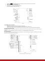
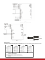
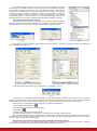
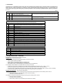
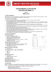
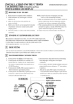
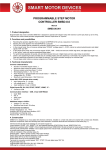
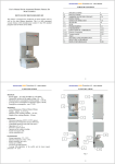
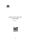
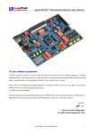
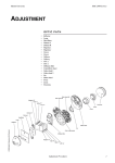
PROGRAMMABLE STEP MOTOR
CONTROLLER SMSD-4.2
Manual
SMSD.42.001
1. Product designation
Programmable step motor controller SMSD-4.2 (the unit) is designed to operate with stepper motor with maximum current per phase up to
4.2 Amp. There are three control modes provided: programmable, manual or simple driver.
2. Functions and possibilities
•
•
•
Recording the operation algorithm from a computer to EEPROM of the unit as a sequence of ASCII commands.
Reading the saved algorithm from the EEPROM to a computer;
In the programmable mode: control the stepper motor as per the program, saved in the unit’s memory. Speed,
acceleration/deceleration, displacement, direction of the stepper motor are set as a sequence of execution commands and is storage in
the nonvolatile memory of the unit.
In the simple driver mode: the unit receives logic signals “PULS” and “DIR” – 0VDC low level and 5-24VDC high level.
In the manual mode: the unit receives analog signal “Speed” (voltage signal 0-5VDC, internal or external potentiometer) and digital
signals “Reverse” and “Enable”.
For synchronized operation of several SMSD-4.2 units and other devices there are 3 digital inputs and one output relay are provided.
These inputs and output relay are used in the programmable mode.
The unit can operate and be controlled by a computer or in a standalone mode.
There is zero positioning function provided: start zero search by a command or by a signal on the digital input. Stop zero searching
movement as input signal is received. The function provides homing by an individual input.
The unit stops motor motion as receives a signal on an “Enable” input.
The unit changes rotation direction as receives a signal on a “Reverse” input (in the manual and programmable modes).
The microstepping can be changed on-fly in the manual and programmable modes.
•
•
•
•
•
•
•
•
3. Technical characteristic
Common characteristics:
•
•
•
•
•
•
•
Dimensions:
Number of controlled stepper motors: 1
Maximum output current per phase: 4,2 Amp
Minimum output current per phase: 0,2 Amp
Microstepping modes: 1/2, 1/4, 1/16
Pulses frequency in programmable and manual modes: 1 - 10000 Hz
Voltage input: 12 - 48 VDC
Maximum overall dimensions: 120х116х26 mm
Inputs DIR, STEP (simple driver mode):
• High voltage level: 5 - 24 VDC
(Please, connect current-limiting resistance when use high level voltage
more, than 5VDC: 1 KOhm for 12VDC, 2 KOhm for 24VDC).
• Low voltage level: 0 - 1 VDC
• Input resistance, no less 3.0 KOhm
Digital inputs EN, Reverse, BX1, BX2:
•
Contact to GND
Communication interface – USB, virtual COM RS232:
•
•
•
•
baud: 9600
bits: 8
parity: even
stop bit: 1
Img. 1
Additional output «5 VDC»:
•
•
•
Voltage: 5 VDC
Maximum load current: 20 mAmp
Resistance: 27 Ohm
Environmental Conditions:
Ambient Temperature: -25…+50°C
Humidity: 90% RH or less upon condition +25°C
Condensation and freezing: none
Pressure: 650…800 mm of mercury
4. Construction
SMSD-4.2 is designed as a circuit plate with electronics elements, installed on a heatsink plate and covered with a metal case. Besides
electronic components, there are indicating and control elements, connection terminals and connectors on the board:
•
•
•
•
terminal screws for power supply, stepmotor windings and control circuit connection;
USB plug for a computer connection;
control buttons “Reset”, “Homing”, “Start”;
internal preset potentiometer «V» to adjust speed in the manual mode;
•
•
•
•
•
connector "
" for an external potentiometer connection to control motor speed in the manual mode;
LED for indication of the controller status;
switches SW1 – SW2 to set the operation mode;
switches SW3 – SW5 to set the microstepping mode;
internal potentiometer to adjust output current.
Img. 2
5. Assembly and connection
Please, learn this manual carefully before connection and assembly.
Please, wire just when power is off. Do not attempt to change wiring while the power is ON.
Please, provide a reliable contact in connection terminals. During wiring, please, observe the polarity and wire management.
Assembly and connection order
1. Connect the SMSD-4.2 controller with stepper motor, switches and electric DC power supplier according to one of schemes shown on
images 3-6.
2. Connect if necessary the SMSD-4.2 controller to a computer by an interface USB cable (included to the set).
Connection schemes
The connection example in the programmable mode is on the image 3, in the simple driver mode – image 4, in the manual mode – image 5.
The switch connection example is on the image 6.
Img. 3
Programmable mode – connection example
Img. 4
Simple driver mode – connection example
GND
+VCC
SWITCH
NPN type
Img. 5
Manual mode – connection example
LOAD
Signal GND
Output +5VDC
“0”, REVERSE
EN, BX1, Bx2
Img. 6
NPN switch connection example
Motor connection
The SMSD-4.2 controller provides operation with 2 or 4-phase stepper motors, 4, 6 or 8 wires. Winding connection examples are in the table 1.
Connect step motor wires to A, A*, B and B* terminals of SMSD-4.2.
Table 1
Scheme 1
Scheme 2
Scheme 3
8 wires stepmotor connection (4 phases):
Scheme 1 – serial connection;
Scheme 2 – parallel connection.
6 wires stepmotor connection (2 phases with midpoint taps):
Scheme 3;
4 wires stepmotor connection (2 phases without midpoint taps):
Scheme 4 .
Scheme 4
6. Before starting
1. Make sure the power supply is turned off.
2. Choose the suitable operation mode and set microswitches SW1 and SW2 according to the table 2.
Table 2
Operation
mode
Microswitch
SW1
SW2
Programmable
ON
ON
Simple driver
OFF
ON
Manual
ON
OFF
Control
As per the preset motion algorithm, saved in the controller’s memory.
Algorithm consists of a sequence of commands – simple instructions.
Pulse and Dir logic signals – low and high level voltage.
Speed is adjusted by a potentiometer or analog signal 0-5VDC,
direction is changed by a logic signal (pulse).
3. Choose suitable microstepping mode and set microswitches SW3 and SW4 according to the table 3. The new microstepping in the simple
driver mode is applied after RESET (by button or input signal).
Table 3
SW3
SW4
1
ON
ON
1/2
ON
OFF
1/4
OFF
ON
1/16
OFF
OFF
4. Make wiring according to the section 5 “Assembly and connection“.
5. Set suitable for the stepper motor current per phase. Please, use the potentiometer “Current” on the board of the controller. Adjust current
according image 7. The output current, set by the potentiometer, should be set according to the motor’s description. Low current leads to a
weak torque of the motor, high current leads to the motor heating and can damage the motor.
Img. 7
Output current adjusting
6. If necessary, connect the SMSD-4.2 controller to a computer by the USB cable, which is supplied with the unit.
7. Check wiring once again and turn on the power supply.
8. If the operation mode should be changed after power on, set SW1 and SW2 according to the table 2 and RESET the controller (by button
or input signal).
If the microstepping mode should be changed after power on, set SW3 and SW4 according to the table 3. In the programmable and manual
mode new microstepping applies at once. In the simple driver mode it is necessary to RESET controller to apply new microstepping mode.
9. To control the stepper motor:
- In the simple driver mode (connection example on the image 4) set the required sequence of logic signals “STEP” and “DIR”
according to the scheme below (image 8).
One step (or microstep) executes as the front edge of the voltage pulse on the “STEP” input. Direction switches by changing voltage
level on the “DIR” input.
The motor can be stopped by the active signal on the “EN” input (clean contact of EN and GND).
Img. 8
STEP and DIR input signals
- In the manual mode (connection example on the image 5) adjust speed by the potentiometer or analog signal 0-5VDC. The motor
speed is changed by the internal potentiometer “SPEED” when jumper "
speed by internal potentiometer, remove jumper "
" is closed. To connect external potentiometer set the minimum
" and connect on this place external potentiometer 10 KOhm. To adjust speed by the
analog signal set the minimum speed by internal potentiometer, remove jumper "
" and connect on this place contacts of analog signal
source (“0V“ at the cover side, “+V” at the heatsink bottom side).
In the manual mode information of current speed of the motor is available via communication interface as the ASCII string. To change
direction set signal to the “REVERSE” input – contact “REVERSE” and logic “GND”. Direction changes as the front edge of the signal.
- In the programmable mode to control via a computer the USB cable connection should be provided. For a standalone operation
the executing program should be saved via USB (virtual RS-232), after that the USB cable can be disconnected. For virtual RS-232
communication the special driver USB-RS-232 should be installed to the computer. Please, save on computer hard drive the installation
pack CP210x_VCP_Win2K_XP_S2K3.zip, which is supplied with the controller SMSD-1.5. Unpack and execute the exe file. Please, follow
the instructions during the installation progress. As a result when the controller is connected to the PC, the additional program COM-port
appears (CP2102 USB to UART Bridge Controller).
The availability and the number of new port can be checked in windows device manager
(Windows XP: On the desktop right-click on My Computer and click Properties or open the
Control Panel and double-click the System icon. In the System Properties window click the
Hardware tab. In the Hardware tab click the Device Manager button) – image 9. This COM-port
should be used for communication with SMSD-4.2 controller. The port properties should be set
in a terminal program according to the section 3 “Technical characteristic“. As a terminal
program SMC_Program or some other software can be used (software should provide RS-232
ASCII communication). The program is available and supplied with the SMSD-4.2 controller.
Saving execute program with SMC_Program
The program should be copied to the hard drive of the computer. Unpack the program
pack. SMC_Program doesn’t require registration and installation. The write/read operations
should be allowed in the program folder (carefully check for windows vista and windows 7).
Img. 12
Img. 13
Img. 9
It is necessary to set port properties in SMC_Program. Menu “Port settings” > «Chose port» (image 12) chose the connected port
number and press “Ok” (image 13).
Img. 10. SMC_Program – control via simple panel
Img. 11. SMC_Program – program assembling
In the simple control panel window (Img. 10) check the box 1, (coordinate 1 – Img.14).
Img. 14
If the program is in the simple control mode (image 10) - input motor operation parameters (steps number, speed, acceleration,
direction) and press the button “write” to record parameters to the controller and press the button “start” to start motion according to the
recorded command sequence. Or press the button “Write and start” to record new parameters and start motion at the moment.
If the program is in the programming control mode (image 11) add to the command list:
1) «Start loading to the coordinate 1»
;
2) Add commands to assemble the operation algorithm.
3) «End loading»
.
4) Press the button «send» under the command list.
Commands list and description are in the section 7. “Commands”, and in the SMC_Program manual.
After the commands sequence (operation algorithm) is recorded into the controller there are two possibilities: to continue control by
the SMC_Program or to use the controller in standalone mode. To start program executing in the standalone mode press the “Start” button
or contact “Start” and “GND” at the controller frame.
Saving execute program with other terminal program with RS-232 communication function
Set the port number (check in the windows device manager, image 9), set port parameters according to the section 3 “Technical
characteristic“. Input required commands sequence using the ASCII codes (table 4, 5; section 7).
7. Commands
Commands in the programmable mode should be byte-serial (character-serial) transferred. Every command should be completed with the
ending character “*”. The ending character “\” instead of “*” cancels previous bytes transfer (whole string). There is the commands list in the
table 4 and 5. The SMSD-4.2 controller receives and checks every command after receiving the ending character “*”. Controller sends to the
communication port a reply after receiving every command (successful or error command). All possible controller replies are presented in
the table 6.
Table 4
Control commands:
Start loading to the controller – after the command
1
LD1
controller is in the loading mode.
Read the command sequence from the controller
2
RD1
memory.
3
ST1
Start or stop the commands sequence executing
4
SP
Temporary stop the commands sequence executing
Can be accepted if the controller in the programmable standby mode.
Start if the controller in the programmable standby mode, stop if the
commands sequence is executing.
Can be accepted if the commands sequence is executing.
Table 5
Executing commands
(accepted in the commands loading mode, executed one by one in the executing mode).
1
BG
Begin - start a new algorithm, the previous sequence is cleared.
Complete executing commands sequence. After accepting this command the controller
2
ED
records all transferred commands into the memory and turns to the standby mode.
3
DL
Forward motion
4
DR
Backward motion
5
RS
Reverse
6
AL(-)ddd
Acceleration ddd: min = -500, max = 500
7
SDddddd
Speed ddddd, max = 10000 steps/sec
8
SSdddd
Start speed dddd, мах = 2000 steps/sec
9
MV
Continuous movement
10
MVddddddd
Move to ddddddd steps, mах = 10 000 000
11
MH
Indefinite movement, till signal to input BX1
12
ML
Indefinite movement, till signal to input BX2
13
HM
Indefinite movement, till signal to input “0” (zero limit switch)
14
SPddddddd
Pause for ddddd ms, mах = 100 000 000
15
LL
Set label for cycle operation
16
JPddd
Repeat from label ddd times, мах=255. Set 2 commands JPddd to create endless cycle.
17
EN
Set “enable” - turn on the motor
18
DS
Set “disable” - turn off the motor
19
WL
Indefinite pause, wait for a signal to input BX2
20
WH
Indefinite pause, wait for a signal to input BX1
Table 6
Reply
E10*
E13*
E14*
E15*
E16*
E19 *
Description
The command successfully accepted
There is the error in the executing program
Program executing completed
Communication Error (check port parameters)
Command error (check controller mode or ASCII code of the command)
Command data error (check command data – integer, in allowed range, see table 5)
8. Programmable mode - submodes
The SMSD-4.2 controller goes in one of the submodes:
Standby mode – red color LED indicator.
The SMSD-4.2 controller goes to the standby mode in one of the next cases:
•
•
•
•
After program executing completed;
After program executing was stopped by command «ST1».
After power on (if microswitches SW1=On and SW2=On);
After “Reset” button or input activated (if microswitches SW1=On and SW2=On).
In the standby mode the SMSD-4.2 controller waits for one of the next event:
•
•
•
•
Arrival one of the control commands from a computer (table 4, accepted commands are «LD1», «RD1», «ST1»);
Start executing program by pressing the button “Start” or input signal “Start” (connect “Start” and “GND”);
Start searching for a limit switch (zero position) by pressing the “Home” button or input signal “Start” (connect “Home” and “GND”);
Turn to the other operation mode: manual or simple driver mode (see section 6 and table 2).
Program executing mode – blink red color LED indicator.
The SMSD-4.2 controller turns to the program executing mode and start motion algorithm from the standby mode in case of:
•
•
“Start” button pressed or input activated (connect “Start” and “GND”);
Arrival the control command «ST1»;
The SMSD-4.2 controller turns back from program executing to the standby mode in case of:
•
•
•
Executing program completed;
Arrival the control command «ST1»;
“Reset” button pressed or input activated (connect “Reset” and “GND”).
The commands of the sequence (operation algorithm) are executed one by one, as they were recorder to the controller. The controller
commutates motor windings according to the executing commands. At the same time SMSD-4.2 controls the inputs state for “BX1”, “BX2”,
“EN”, “Reverse”, “0”.
Active “EN” signal suspends and inactive signal resumes the program executing. Active “Reverse” signal changes motion direction (by the
front edge). “BX1”, “BX2” and “0” signals are handed according to the current executing command.
Waiting for an external signal submode – red color LED indicator.
The SMSD-4.2 controller turns to this submode during program executing, as per the command “WH” or “WL” – waiting for an external
signal. The controller suspends program executing till receiving active signal to input BX1 or BX2. As the signal arrives to BX1 or BX2 (as
per the command) the controller resumes program executing.
Commands loading to the controllers memory – orange color LED indicator.
The SMSD-4.2 controller turns to this mode from the standby mode as receives the command “LD1”. In the commands loading mode the
controller accepts the executing commands only (table 5). After arriving the command “ED” the controller record all received executing
commands to the memory and turns to the standby mode.
Reading commands from the controller – orange color LED indicator.
The SMSD-4.2 controller turns to this mode from the standby mode. The sequence of executing commands from the controller memory
transfers to the computer as the controller receives the command “RD1”. After the commands transferred the controller turns back to the
standby mode.
Temporary stop mode – blink orange color LED indicator.
The SMSD-4.2 controller turns to this submode during program executing as receives the signal «EN» (contact «EN» and «GND»). The
controller suspends program executing while the signal is active. As the signal turns to inactive the controller resumes the program
executing.
Executing program error – blink orange color LED indicator.
The SMSD-4.2 controller turns to this submode during program executing in case of wrong command in the sequence. The exit of this mode
as “Reset” button pressed or input activated (connect “Reset” and “GND”). The executing program should be recorded again to the
controller memory.
9. Delivery in complete sets
The stepper motor controller SMSD-4.2
USB cable
SMC_Program can be delivered on a CD or by e-mail
Manual SMSD.42.001
Switch (Hall effect) SM8-31010NA – as an option, extra cost, on a request
1 pcs.
1 pcs.
1 pcs.
1 pcs.
1 pcs.
10. Warranty
Any repair or modifications are performed by the manufacturer or an authorized company.
The manufacturer guarantees the failure-free operation of the controller for 12 months since date of sale when the operation conditions are
satisfied – section 3.
The manufacturer sales department address: Smart Motor Devices OÜ,
Tallinn Science Park Tehnopol, Mäealuse st. 4, Tallinn 12618, Estonia,
Phone: + 372 6559914,
e-mail: [email protected]
url: http://www.stepmotor.biz