1
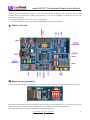
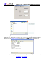
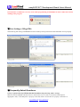
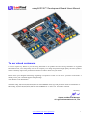
easyAVR128™ Development Board Users Manual
To our valued customers
I want to express my thanks to you for being interested in our products and for having confidence in LogiFind
International CO,. Ltd..The primary aim of our company is to design and produce high quality electronic products
and to constantly improve the performance thereof in order to better suit your needs.
Please share your thoughts and feelings regarding our operation so that we can serve you better in the future. I
thank you for your continued support and patronage.
Your Dream is our Destination!
The Microchip, TI,Freescale,ST,Atmel,Silicon and CYPRESS name, logo and products names are trademarks of
Microchip, TI,Freescale,ST,Atmel,Silicon and CYPRESS Inc. in the U.S.A. and other countries.
Sincerely,
Owner and General Manager
of LogiFind International CO,. Ltd.
www.100mhz.com www.LogiFind.com
1
easyAVR128™ Development Board Users Manual
CONTENTS
Ⅰ.What is easyAVR128™?........................................................................................................................................ 3
Ⅱ.Appliance................................................................................................................................................................ 3
Ⅲ.Power supply...........................................................................................................................................................3
Ⅳ.Hardwre Connection description............................................................................................................................. 3
Ⅴ.What’s on board...................................................................................................................................................... 4
Ⅵ.Bootloader programming........................................................................................................................................4
Ⅷ.Frequently Asked Questions............................................................................................................................... 7
1).I try to power the easyAVR128, but the board does not power up, what’s wrong?........................................7
2) How is power supplied to the easyAVR128?.................................................................................................. 8
3) The Mega128A is no longer accessible via programmer/debugger, is something wrong with the device?....8
4) I have uploaded the Mega128A sample code, but It doesn’t seem to be working, what’s wrong?.................8
5) I loaded the Mega128A sample code using an external, after that,i found the bootloader doesn’t work any
more...................................................................................................................................................................... 8
IX.Schematic............................................................................................................................................................... 9
X.Contact Us............................................................................................................................................................... 9
Disclaimer................................................................................................................................................................... 10
www.100mhz.com www.LogiFind.com
2
easyAVR128™ Development Board Users Manual
Ⅰ.What is easyAVR128™?
The easyAVR128 Board is a complete solution for fast and simple development of embedded applications by
using a new Atmel® ATmega128A device connected to 7.3728Mhz oscillator.It has a bootloader inside the
ATmega128A,and it allows self-programming very easily without an external programmer or debugger.
Key features:
- Bootloader program loaded into the ATmega128A microcontroller;
- CP2102 USB to UART converter for RS232 communication and bootloader programming.
- 5V and 3.3V power supply;
- RS232 Circuit with DB9 connector;
- 5V,3.3V and GND PINOUTs for DIY;
- 8 user LEDs;
- System Reset Key;
- DS1302 Real Time Clock;
- 24C02 eeprom;
- Standard ISP6 connector;
- Standard ISP10 connector;
- Standard JTAG connector;
- 8 user KEYs;
- Stepmotor with driver circuit;
- Buzzer with driver circuit;
- Standard LCD1602 socket;
- Standard LCD12864 socket;
- ADC0 and ADC1 input;
- DS18B20 Temp sensor socket;
- INT0 and INT1 input;
- 8 digit 7-segment LED display;
- All Ios are taken out;
Ⅱ.Appliance
The easyAVR128 Board represents a development system which can be used as a stand-alone device. it has many
users among students, hobbyists, enthusiasts and professionals. We Due to its preloaded bootloader program and
8-bit MCU it is ideal for low-cost experimenting and final product design.
Ⅲ.Power supply
For connection with a power supply source the easyAVR128 Board uses a Jack EX-PWR. The power supply
voltage level can vary from +7-10V DC. When programming the MCU via bootloader,it is necessary
to connect the board to a PC via a USB cable and the external power supply is no need during this time.
Ⅳ.Hardwre Connection description
1. For easy access to the pins of the MCU supplied on the easyAVR128 Board you can use pads. Every pad is
clearly marked with a pin name to which it is connected to.
2. To connect the easyAVR128 Board to a PC it is necessary to connect the USB port on the PC to a USB
connector USB/POWER using a USB cable. When connection is established the PC will communicate with
www.100mhz.com www.LogiFind.com
3
easyAVR128™ Development Board Users Manual
CP2102 chip which is connected to MCU pins PD2,PD3,PE0 and PE1. These pins are used for serial UART0 or
UART1 communication.We set UART1 as the bootloader MODE channel.In other word,you must connect
UART1 jumpers and disconnect UART0 jumpers when you are using bootloader to upload hex file into your
target device mega128A.
4. The ISP6 and ISP10 connector is used for programming.
5. The JTAG connector is used for programming/debugging via the JTAG interface.
Ⅴ.What’s on board
Ⅵ.Bootloader programming
In order to program the MCU via bootloader it is necessary to place the proper jumpers like the following figure.
By doing so connection between the cp2102 chip and the MCU will be enabled. If you want to use MCU pins
which are used for programming (PD2 and PD3) as I/O you should remove the related jumpers.
Follow the steps below for program installation and MCU programming.
www.100mhz.com www.LogiFind.com
4
easyAVR128™ Development Board Users Manual
Step1.Instal CP2102 driver
Before you connect your easyAVR128 board to a computer running Microsoft Windows, you should install its
drivers:
Download the CP2102 drivers for Windows from here:
http://www.silabs.com/products/mcu/Pages/USBtoUARTBridgeVCPDrivers.aspx
Any details,pls see “Silicon CP2102 SETUP GUIDE.pdf” we provided in CD/DVD rom.
Step2.Run “AVRUBD” software
Step3.Go to the Device Manager to see which com port is created
Step4. Com Port Setting
Enter Option/Comport to set the correct Com Port,and click “OK”.
www.100mhz.com www.LogiFind.com
5
easyAVR128™ Development Board Users Manual
Step5. Load HEX file
Enter File/Load to load HEX file into the AVRUBD software,and click “Open”.
Step6. Start to Program
Press RESET key to force the AVR device into the bootloader MODE,and then you will see the BOOT led
blinking with about 3Hz frequency.At this time,the AVR device will stay in bootloader MODE within 5s.During
this time,you can enter Operation/Download or press F9 key(PC) or click
to start to download HEX file.
After downloading is finished,the application program will be running.If you want to upload the new HEX file,
you have to press RESET key again to enter bootloader MODE.
www.100mhz.com www.LogiFind.com
6
easyAVR128™ Development Board Users Manual
PS:Sometimes an unknown error may occur when programming is finished,but it dosen’t affect the normal
running of the program.
Ⅶ.Fuse Settings of Mega128A
The following fuse setting in AVRStudio has been made by factory,which ensure the bootloader can run properly.
Ⅷ.Frequently Asked Questions
1).I try to power the easyAVR128, but the board does not power up, what’s wrong?
Make sure that the POWER LED has turned on. If the LED is not on, check to see that the external power
supply(DC7-10V) or the USB power is properly connected, check to see that the J2 is properly connected .It is
www.100mhz.com www.LogiFind.com
7
easyAVR128™ Development Board Users Manual
necessary to note that the external power supply(DC7-10V) and the USB power can not be connected at the same
time.According to the designer’s experiences,the FUSE on board is also an important factor.
2) How is power supplied to the easyAVR128?
Two supply options exist: USB power Cables and external 7—10VDC. You are only allowed to choose one of
them.
3) The Mega128A is no longer accessible via programmer/debugger, is something wrong with the device?
- Verify that the target device is powered properly.
- If the target is powered locally, verify your programmer/debugger is connected properly.
- If the programmer/debugger is connected properly, the Mega128A is possibly "dead". Well, it's not really dead,
it's just that it can't be reprogrammed until the Mega128A is unlocked (for detailed method of unlocking an AVR
device, please search for solution on-line).
4) I have uploaded the Mega128A sample code, but It doesn’t seem to be working, what’s wrong?
- Make sure the relational jumper is correctly connected.
- If the relational jumper is correctly connected, pls check whether the device mode had been changed to
“mega103”mode,In “mega103”mode, the mega128A features are not fully reflected.
-If you are using PD2 and PD3 in you source code,close the UART1(add “UCSR1B=0”in “main” of your source
code).
5) I loaded the Mega128A sample code using an external, after that,i found the bootloader doesn’t work any
more.
The bootloader is erased after you upload hex file to the mega128A using external programmer.So you have to
re-upload bootloader by yourself if you want to use bootloader self-programming function.
www.100mhz.com www.LogiFind.com
8
easyAVR128™ Development Board Users Manual
IX.Schematic
4
104
J2
3.3V
2
C5
+
C4
VCC
LCD1602
VOUT
104
L8
LEDs
R18
VCC
KEY1
R19
KEY2
R20
SW7
J8
KEY3
PB0
PB1
PB2
PB3
PB4
PB5
PB6
PB7
ON
ON
ON
ON
ON
ON
ON
ON
R21
KEY4
R22
KEY5
R23
KEY6
R24
PEN
PE0
PE1
PE2
PE3
PE4
PE5
PE6
PE7
PB0
PB1
PB2
PB3
PB4
PB5
PB6
PA3
PA4
PA5
PA6
PA7
PG2
PC7
PC6
PC5
PC4
PC3
PC2
PC1
PC0
PG1
PG0
48
47
46
45
44
43
42
41
40
39
38
37
36
35
34
33
PA3
PA4
PA5
PA6
PA7
PG2
PC7
PC6
PC5
PC4
PC3
PC2
PC1
PC0
PG1
PG0
PG4
PD0
PD1
ON
ON
ON
ON
ON
ON
6
5
RST
RST
D1
17
18
19
20
21
22
23
24
25
26
27
28
29
30
31
32
PD0
PD1
PD2
PD3
PD4
PD5
PD6
PD7
28
27
26
25
24
23
22
POWERSW
6
GND
DATA+
DATAVCC
5
DTR
DSR
TXD
RXD
RTS
CTS
NC
104
VCC
SW9
C25
1
3
5
7
9
PF7
1
3
5
7
9
VCC
R27
3
4.7K
2
1
DS18B20/ADC
ISP10
2
4
6
8
10
2
4
6
8
10
PF0
PF1
PC7
ON
ON
ON
JTAG
PF4
PF6
PF5
C
PC0
PC1
PC2
PC3
PG3
1
3
5
7
9
PE0
VCC
RST
RST
PB1
PE1
1
3
5
7
9
2
4
6
8
10
VCC
2
4
6
8
10
ISP6
1
3
5
PE1
PB1
RST
1
3
5
2
4
6
VCC
2
4
6
PE0
B
JTAG&ISP
11
7
4
2
1
10
5
3
A 15
B 1
C 2
D 3
E 4
F 5
G 6
DP 7
SEG2
SEG1
11
12
14
SRCLK
RCLK
SER
QA
QB
QC
QD
QE
QF
QG
GH
13
8
OE
GND
10
16
9
SRCLK
VCC
QH
Y0
Y1
Y2
Y3
Y4
Y5
Y6
Y7
Q6
Q7
Y7
Y6
Q5
Y5
Q4
Y4
Q3
Q1
Q2
Y3
Y2
R30
R31
R32
R33
R34
R35
R36
R37
Y1
15
14
13
12
11
10
9
7
6
3
2
1
G1
C
B
A
Y0
Y1
Y2
Y3
Y4
Y5
Y6
Y7
16
VCC
SW11
J12
VCC
VCC
C21
4
5
8
G2A
G2B
GND
PA1
PA2
PA3
PA4
PA5
PA6
PA7
ON
ON
ON
ON
ON
ON
ON
VCC
A
104
Y0
Title
R15
10K
RESET
VCC
C20
3.3V
PD0
PD1
Q8
SW8
ULN2003A
ADC0
74HC138
INT SOURCE
VCC
DQ
PC0
PC1
PC6
12
ON
ON
10K
2
4
6
SW10
J11
VCC
10K
R29
2
4
6
C26
104
VCC
RTC
R28
INT1
1
3
5
VCC
6
GND
104
SW6
J7
20P
INT0
1
3
5
DS1
I/O
C15
VCC
7
J9
J10
DS18B20
A
B
C
D
E
F
G
DP
X2
8
2
4
6
GND
DS3
SLCK
VCC
ADC1
7
6
5
4
3
2
1
IN7
IN6
IN5
IN4
IN3
IN2
IN1
2
4
6
3.3V
12
4
VCC1
X1
VCC
5V
GND
DS0
3
1
3
5
20P
6
Y2
C17
VCC2
A
B
C
D
E
F
G
DP
2
DS3
1
STEPMOTOR/BUZZER
8
GND
OUT7
OUT6
OUT5
OUT4
OUT3
OUT2
OUT1
3.3V
1
3
5
11 A
B
7
C
4
D
2
E
1
10 F
G
5
3 DP
C16
VCC
10
11
12
13
14
15
16
5
4
3
2
1
D
C
B
A
VCC
VCC
74HC595
DS1302
20P
C13
104
7-SEGMENT
DS1
6
5
24CXX
8
SCL
SDA
J6
2
4
6
2
4
6
POWER INTERFACE
DS2
R16
VCC
GND
1
3
5
5V
SW5
9
8
4
1
3
5
20P
7
R17
VCC
5V
BOOT
Y1
PB7
PG3
PG4
RST
VCC
GND
B
WP
6
4
3
2
1
5
ATMEGA128/64
1
2
3
4
5
6
7
8
9
10
11
12
13
14
15
16
BUTTONs
EEPROM
VCC
A0
A1
A2
1
C18
9
VCC
C24
R25
LED0
BEZZER
KEY7
KEY8
1
2
3
5V
R1
VCC
R38
1K
PEN
PE0
PE1
PE2
PE3
PE4
PE5
PE6
PE7
PB0
PB1
PB2
PB3
PB4
PB5
PB6
J1
POWER&USB-RS232
VCC
DS2
1K
C23
104
8
R14
104
L7
1K
R2
1K
5V
10u
Stepmotor
L6
1K
R13
C3
+
C2
D
21
20
19
18
17
16
15
NC
NC
NC
NC
NC
NC
NC
1K
9
R12
C
L5
1K
C22
PC0
PC1
PC2
PC3
PC4
PC5
PC6
PC7
ON
ON
ON
ON
ON
ON
ON
ON
DCD
RI
GND
D+
DVDD
REGIN
104
DS0
J5
R11
VCC
SW4
PF0
PF1
PF2
PF3
PF4
PF5
PF6
PF7
GND
VCC
PA0
PA1
PA2
L4
MICROCONTROLLER
GND
L3
3
VIN
64
63
62
61
60
59
58
57
56
55
54
53
52
51
50
49
1K
R10 1K
R9
D+
DC1
104
L1
AVCC
GND
AREF
PF0
PF1
PF2
PF3
PF4
PF5
PF6
PF7
GND
VCC
PA0
PA1
PA2
1K
L2
470u
LM1117-3.3
3.3V
LCD12864
PB7
PG3
PG4
RESET
VCC
GND
XTAL2
XTAL1
PD0
PD1
PD2
PD3
PD4
PD5
PD6
PD7
L1
CP2102
1
2
3
4
5
6
7
PD2
PE0
PD3
PE1
1K
R8
C7
+
104
+
R7
3
C6
+5V
5V
10u
VCC
A
VCC
5V
Vin
SW1
C19
1
FUSE
RC6
RC7
10K
L7805
VBUS
RST
NC
SUSPEND
SUSPEND
NC
NC
By Jeff
WWW.LogiFind.COM
5V
USB/POWER
ON
ON
ON
ON
EasyAVR128
5V
R26
D1
1
8
9
10
11
12
13
14
VCC
J3
PA5
PA6
PA7
PD0
PD1
PD2
PD3
PD4
PD5
PD6
PD7
VCC
POWERLED
PE0
PD2
PE1
PD3
ON
ON
ON
ON
2
GND
5V
GND
J3
1
2
3
4
5
6
7
8
9
10
11
12
13
14
15
16
1
2
3
4
5
6
7
8
9
10
11
12
13
14
15
16
2
SW2
12864-VOL
9
10
11
12
13
14
15
16
R2 OUT
T2 IN
T1 IN
R1 OUT
R1 IN
T1 OUT
GND
VCC
POWER
LCD1602
1602-VOL
R2 IN
T2 OUT
VV+
C2C2+
C1C1+
5V
PA5
PA6
PA7
PD0
PD1
PD2
PD3
PD4
PD5
PD6
PD7
3
2
1
VCC
104
RS232
8
7
ON
ON
ON
ON
ON
D
C25
105
8
7
6
C8
2
C10 5
4
3
C9
1
1
2
3
4
5
6
7
8
9
10
11
12
13
14
15
16
17
18
19
20
1
2
3
4
5
6
7
8
9
10
11
12
13
14
15
16
17
18
19
20
VCC
5
9
4
8
3
7
2
6
1
6
5V
1
2
3
C12
UART
5
5V
LCD12864
GND
3
RS232
OFF
2
ON
1
8550
8550
VCC
8550
8550
8550
8550
8550
8550
Size
C14 104
VCC
VCC
VCC
VCC
VCC
VCC
VCC
RESET
1
2
Date:
File:
3
4
5
Number
Revision
A3
VCC
6
16-Jan-2006
E:\100MHZ\100MHZ.Ddb
7
Sheet of
Drawn By:
8
X.Contact Us
Official Website:www.100MHz.com
www.LogiFind.com
ebay Store 1: http://stores.ebay.com/logifind
ebay Store 2: http://stores.ebay.com/kitfind
E-mail:[email protected]
[email protected]
Skype: love100mhz
www.100mhz.com www.LogiFind.com
9
easyAVR128™ Development Board Users Manual
Disclaimer
© 2013 LogiFind International CO,. Ltd. All rights reserved. LogiFind®, logo and combinations thereof, are
registered trademarks of LogiFind International CO,. Ltd. Other terms and product names may be trademarks of
others.
The information in this document is provided in connection with LogiFind products. No license, express or
implied or otherwise, to any intellectual property right is granted by this document or in connection with the sale
of LogiFind products.Neither the whole nor any part of the information contained in or the product described in
this document may be adapted or reproduced in any material from except with the prior written permission of the
copyright holder.The product described in this document is subject to continuous development and improvements.
All particulars of the product and its use contained in this document are given by LogiFind in good faith. However
all warranties implied or expressed including but not limited to implied warranties of merchantability or fitness for
purpose are excluded.This document is intended only to assist the reader in the use of the product. LogiFind
International CO,. Ltd.shall not be liable for any loss or damage arising from the use of any information in this
document or any error or omission in such information or any incorrect use of the product.
www.100mhz.com www.LogiFind.com
10