1
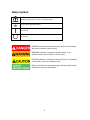
Model: 9110, 9111 Multi Range DC Power Supply USER MANUAL 1 Safety Summary The following safety precautions apply to both operating and maintenance personnel and must be followed during all phases of operation, service, and repair of this instrument. Before applying power to this instrument: • • • • • Read and understand the safety and operational information in this manual. Apply all the listed safety precautions. Verify that the voltage selector at the line power cord input is set to the correct line voltage. Operating the instrument at an incorrect line voltage will void the warranty. Make all connections to the instrument before applying power. Do not operate the instrument in ways not specified by this manual or by B&K Precision. Failure to comply with these precautions or with warnings elsewhere in this manual violates the safety standards of design, manufacture, and intended use of the instrument. B&K Precision assumes no liability for a customer’s failure to comply with these requirements. Category rating The IEC 61010 standard defines safety category ratings that specify the amount of electrical energy available and the voltage impulses that may occur on electrical conductors associated with these category ratings. The category rating is a Roman numeral of I, II, III, or IV. This rating is also accompanied by a maximum voltage of the circuit to be tested, which defines the voltage impulses expected and required insulation clearances. These categories are: Category I (CAT I): Measurement instruments whose measurement inputs are not intended to be connected to the mains supply. The voltages in the environment are typically derived from a limited-‐ energy transformer or a battery. Category II (CAT II): Measurement instruments whose measurement inputs are meant to be connected to the mains supply at a standard wall outlet or similar sources. Example measurement environments are portable tools and household appliances. Category III (CAT III): Measurement instruments whose measurement inputs are meant to be connected to the mains installation of a building. Examples are measurements inside a building's circuit breaker panel or the wiring of permanently-‐installed motors. Category IV (CAT IV): Measurement instruments whose measurement inputs are meant to be connected 2 to the primary power entering a building or other outdoor wiring. Do not use this instrument in an electrical environment with a higher category rating than what is specified in this manual for this instrument. You must ensure that each accessory you use with this instrument has a category rating equal to or higher than the instrument's category rating to maintain the instrument's category rating. Failure to do so will lower the category rating of the measuring system. Electrical Power This instrument is intended to be powered from a CATEGORY II mains power environment. The mains power should be 120 V RMS or 240 V RMS. Use only the power cord supplied with the instrument and ensure it is appropriate for your country of use. Ground the Instrument To minimize shock hazard, the instrument chassis and cabinet must be connected to an electrical safety ground. This instrument is grounded through the ground conductor of the supplied, three-‐conductor AC line power cable. The power cable must be plugged into an approved three-‐conductor electrical outlet. The power jack and mating plug of the power cable meet IEC safety standards. Do not alter or defeat the ground connection. Without the safety ground connection, all accessible conductive parts (including control knobs) may provide an electric shock. Failure to use a properly-‐ grounded approved outlet and the recommended three-‐conductor AC line power cable may result in injury or death. Unless otherwise stated, a ground connection on the instrument's front or rear panel is for a reference of potential only and is not to be used as a safety ground. Do not operate in an explosive or flammable atmosphere 3 Do not operate the instrument in the presence of flammable gases or vapors, fumes, or finely-‐divided particulates. The instrument is designed to be used in office-‐type indoor environments. Do not operate the instrument • • • • • • • In the presence of noxious, corrosive, or flammable fumes, gases, vapors, chemicals, or finely-‐divided particulates. In relative humidity conditions outside the instrument's specifications. In environments where there is a danger of any liquid being spilled on the instrument or where any liquid can condense on the instrument. In air temperatures exceeding the specified operating temperatures. In atmospheric pressures outside the specified altitude limits or where the surrounding gas is not air. In environments with restricted cooling air flow, even if the air temperatures are within specifications. In direct sunlight. This instrument is intended to be used in an indoor pollution degree 2 environment. The operating temperature range is 0 °C to 40 °C and the operating humidity range is ≤ 80% relative humidity with no condensation allowed. Measurements made by this instrument may be outside specifications if the instrument is used in non-‐ office-‐type environments. Such environments may include rapid temperature or humidity changes, sunlight, vibration and/or mechanical shocks, acoustic noise, electrical noise, strong electric fields, or strong magnetic fields. Do not operate instrument if damaged If the instrument is damaged, appears to be damaged, or if any liquid, chemical, or other material gets on or inside the instrument, remove the instrument's power cord, remove the instrument from service, label it as not to be operated, and return the instrument to B&K Precision for repair. Notify B&K Precision of the nature of any contamination of the instrument. Clean the instrument only as instructed 4 Do not clean the instrument, its switches, or its terminals with contact cleaners, abrasives, lubricants, solvents, acids/bases, or other such chemicals. Clean the instrument only with a clean dry lint-‐free cloth or as instructed in this manual. Not for critical applications This instrument is not authorized for use in contact with the human body or for use as a component in a life-‐support device or system. Do not touch live circuits Instrument covers must not be removed by operating personnel. Component replacement and internal adjustments must be made by qualified service-‐trained maintenance personnel who are aware of the hazards involved when the instrument's covers and shields are removed. Under certain conditions, even with the power cord removed, dangerous voltages may exist when the covers are removed. To avoid injuries, always disconnect the power cord from the instrument, disconnect all other connections (for example, test leads, computer interface cables, etc.), discharge all circuits, and verify there are no hazardous voltages present on any conductors by measurements with a properly-‐operating voltage-‐ sensing device before touching any internal parts. Verify the voltage-‐sensing device is working properly before and after making the measurements by testing with known-‐operating voltage sources and test for both DC and AC voltages. Do not attempt any service or adjustment unless another person capable of rendering first aid and resuscitation is present. Do not insert any object into an instrument's ventilation openings or other openings. Hazardous voltages may be present in unexpected locations in circuitry being tested when a fault condition in the circuit exists. Fuse replacement Fuse replacement must be done by qualified service-‐trained maintenance personnel who are aware of the instrument's fuse requirements and safe replacement procedures. Disconnect the instrument from the power line before replacing fuses. Replace fuses only with new fuses of the fuse types, voltage 5 ratings, and current ratings specified in this manual or on the back of the instrument. Failure to do so may damage the instrument, lead to a safety hazard, or cause a fire. Failure to use the specified fuses will void the warranty. Servicing Do not substitute parts that are not approved by B&K Precision or modify this instrument. Return the instrument to B&K Precision for service and repair to ensure that safety and performance features are maintained. Cooling fans This instrument contains one or more cooling fans. For continued safe operation of the instrument, the air inlet and exhaust openings for these fans must not be blocked nor must accumulated dust or other debris be allowed to reduce air flow. Maintain at least 25 mm clearance around the sides of the instrument that contain air inlet and exhaust ports. If mounted in a rack, position power devices in the rack above the instrument to minimize instrument heating while rack mounted. Do not continue to operate the instrument if you cannot verify the fan is operating (note some fans may have intermittent duty cycles). Do not insert any object into the fan's inlet or outlet. Do not short-‐circuit batteries When using a DC load to discharge a battery, do not exceed the battery manufacturer's specified maximum rate of discharge. Use correctly sized wires To connect the load to the power supply, use a wire diameter large enough to handle the maximum continuous output short-‐circuit current of the power supply without the wire overheating. For continued safe use of the instrument • • • • • Do not place heavy objects on the instrument. Do not obstruct cooling air flow to the instrument. Do not place a hot soldering iron on the instrument. Do not pull the instrument with the power cord, connected probe, or connected test lead. Do not move the instrument when a probe is connected to a circuit being tested. 6 Compliance Statements Disposal of Old Electrical & Electronic Equipment (Applicable in the European Union and other European countries with separate collection systems) This product is subject to Directive 2002/96/EC of the European Parliament and the Council of the European Union on waste electrical and electronic equipment (WEEE) , and in jurisdictions adopting that Directive, is marked as being put on the market after August 13, 2005, and should not be disposed of as unsorted municipal waste. Please utilize your local WEEE collection facilities in the disposition of this product and otherwise observe all applicable requirements. 7 CE Declaration of Conformity The instrument meets the requirements of 2006/95/EC Low Voltage Directive and 2004/108/EC Electromagnetic Compatibility Directive with the following standards. Low Voltage Directive - EN61010-‐1: 2001 - EN 61000-‐3-‐2: 2006 EN 61000-‐3-‐3: 1995+A1: 2001+A2: 2005 EN 61000-‐4-‐2 / -‐3 / -‐4 / -‐5 / -‐6 / -‐11 EN 61326-‐1: 2006 EMC Directive 8 Safety Symbols CAUTION indicates a hazardous situation which, if not avoided, could result in minor or moderate injury. Chassis (earth ground) symbol. On (Power) Off (Power) DANGER indicates a hazardous situation which, if not avoided, will result in death or serious injury. WARNING indicates a hazardous situation which, if not avoided, could result in death or serious injury. CAUTION indicates a hazardous situation which, if not avoided, could result in minor or moderate injury. Safety instructions (or equivalent) signs indicate specific safety-‐ related instructions or procedures. 9 Front Panel layout Set Voltage indicator CC mode indicator Voltage value CV mode indicator OCP indicator Cursor position B or preset B is active Cursor position A or preset A is active OVP indicator Cursor position C or preset C is active Cursor position D or preset D is active Preset mode indicator Keys locked indicator Current value Shift mode indicator Output off indicator Set Current indicator Recall Preset values Store voltage-ampere combination (Shift) Move cursor left or store/recall preset B values Move cursor left or store/recall preset A values Keyboard lock (Shift) Enter OVP, OCP, preset mode Enter or store/recall preset C values Toggle between Voltage/Current setting or store/recall preset D Display Voltage and Current setting Secondary function key Output on/off knob Air flow input Output Ground Main Power on/off 10 Introduction The 9110 and 9111 are unlike conventional power supplies with fixed output ratings. They automatically recalculate voltage/current limits for each setting, forming a constant power, hyperbolic shaped boundary, as illustrated in the diagram below. Any Volt/Amp combination that doesn’t exceed 100W, 60V or 5A (or 180W, 60V or 8A for 9111) can be set. By providing greatly expanded choices of maximum power volt-ampere combinations, users can cut down on the number of power supplies required and free up valuable bench space. Example (9110): When setting the voltage to the maximum value of 60V, the max. current value is 100W / 60V = 1.66A. For a 10V setting, the max current is limited to 5A, in which case the maximum output power is only 50W. A maximum output power of 100W is possible for all V/A combination that lie on the hyperbolic curve. 9111 9110 11 Features Digitally controlled, mixed linear/switching mode DC power supply 10mV/1mA resolution over the full range Bright, easy to read display Low ripple and noise Very compact size and light weight Output ON/OFF Control High reliability due to OVP, OCP and OTP (over voltage, over current, over temperature) protection CV (Constant Voltage) and CC (Constant Current) operation Store/Recall 100 groups with 4 sets of Volt/Amp memories each 12 Installation Please inspect the instrument mechanically and electrically upon receiving it. Unpack all items from the shipping carton, and check for any obvious signs of physical damage that may have occurred during transportation. Report any damage to the shipping agent immediately. Save the original packing carton for possible future reshipment. Every instrument is shipped with the following contents: • • • 1x 9110/9111 DC Power Supply 1x User Manual 1x AC Power Cord Verify that all items above are included in the shipping container. If anything is missing, please contact B&K Precision. Input Power The power supply has a universal AC input that accepts a line voltage with a nominal input of 110 V or 220 V AC. Use the line voltage selector switch in the back to switch between 110 V and 220 V operation. Disconnect all cables including the power cord from the instrument when changing the instrument's line voltage. After changing the line voltage setting, ensure the instrument has fuses of the proper ratings and types for the selected line voltage before applying line power. Fuse Requirements An AC input fuse is necessary when powering the instrument. Below is a table of the fuse required for all models operating with either 110 VAC or 220 VAC input. Model 9110 9111 Fuse Specification (110 VAC) T 3.15 A, 250 V T 5 A, 250 V 13 Fuse Specification (220 VAC) T 2.50 A, 250 V T 3.15 A, 250 V Fuse Replacement Follow the steps below to replace or check the fuse. 1. Locate the fuse box next to the AC input connector in the rear panel. 2. With a small flat blade screwdriver, insert into the fuse box slit to pull and slide out the fuse box as indicated below. 3. Check and replace fuse (if necessary) for the desired line voltage operation (see Error! Reference source not found.). Fuse box slit Fuse box Check/Remove Fuse Power-on procedure Turn on the instrument by pressing the main power switch on the front panel of the unit. The instrument will automatically revert to the last setting before the power was turned off. NOTE The 9 pin D-sub connector in the rear is for factory use only! This instrument does not offer a remote control interface. 14 Quick Start Press the Set Voltage D V/A Set Voltage 9110 key to turn the “V” CV CC OVP OCP 100W Multi Range 60V/5A DC Power Supply indicator on. Now you can set the voltage B value. Use the cursor keys A to highlight the desired digit then adjust its value with the knob. In this example the cursor is set to position B and the voltage value can be adjusted in 1V increments. A C B D Lock Preset OFF Shift CV CC OVP OCP cursor in B position Set Current Press the D V/A key to turn on the “A” 9110 100W Multi Range 60V/5A DC Power Supply indicator. Now you can set the current B value. Use cursors A to highlight the desired digit then adjust its value with the knob. A C B D In this example the cursor is set to position A and the current value can be adjusted in 1A increments. 9110 CV CC OVP OCP 100W Multi Range 60V/5A DC Power Supply V A B C D for 3 seconds and the set value for Volts and Amps is displayed. Afterwards, if the instrument has been set to ON, the actual output values for voltage and current are displayed. A Turn output On/Off Press On/Off to toggle the output between ON or OFF. The OFF LED is lit when the output is turned off. Each time you press the On/Off key, the display will blink Lock Set Current cursor in A position V A Lock Preset OFF Shift Output OFF Indicator 15 Cursor Position and Step Size Cursor position Voltage step size Current step size A 1A B 1V 0.1A C 0.1V 0.01A D 0.01V 0.001A Check the Set Voltage and Set Current Value The power supply usually displays the actual voltage and current value. Press Shift twice to check the set value for voltage and current. The display will blink for 3 seconds while displaying the set values. Key Lock Function This function locks the keyboard to prevent unintended modification of power supply settings. Press Shift (Shift LED will be lit), followed by the C (Lock) key. Now the keys and the knob are locked and the Lock LED is lit. Press the Shift key followed by the Lock key again to disable the Lock function. OVP Function Press D V/A then press and hold the (Setup) key for 3 seconds. Note A C B D V OCP Lock A OVP Value OFF Shift CV CC OVP OCP Lock Preset 9110 100W Multi Range 60V/5A DC Power Supply V B C OCP Value 16 A Preset The output of the power supply will automatically turn off if the OVP and OCP value are less than the actual voltage and current value. OVP OCP Function CC CV 100W Multi Range 60V/5A DC Power Supply Afterwards the LCD will display OVP and you can adjust the OVP value using B the cursor keys A and the knob. After the OVP value is set, press C to enter OCP mode. Use the cursor keys A B and the knob to set the OCP value. 9110 Shift D A OFF Shift Once the OCP value is set, press 9110 Key sound C to enter the BEEP mode. Use the knob to turn the key sound ON or OFF. Press C to confirm. 100W Multi Range 60V/5A DC Power Supply V A A B B C C D D CV CV CC OVP OCP Lock Prog OFF Shift A Set address 9110 CV CC Lock Prog OFF Shift 100W Multi Range 60V/5A DC Power Supply Press twice to skip the address menu and advance to the group menu. C V Note: A B C D This setting is for factory use only and can be ignored. A To enter this mode, you have to step through the previous 4 modes first. From address mode, press C to enter group 9110 100W Multi Range 60V/5A DC Power Supply CV CC V B mode. Use the cursors A and the knob to select a group number. There are 100 groups, each group can store 4 sets of voltage/current values. Press C to confirm the entry of the selected group number. Selecting a Group Number A 17 OVP OCP Lock Preset OFF Shift Storing Voltage/Current sets Store up to four sets of voltage/current values to the group number assigned in the previous paragraph. Press Shift followed by the A (Save) key. All 4 cursor LEDs A B C D B C D V/A will blink simultaneously. Press one of the A keys to assign one of the 4 available memory location within this group. Proceed accordingly for the other 3 sets. Preset Mode Press Shift followed by the B (Preset) key. The Preset LED will turn on to indicate that the Preset mode is now active. The most recently selected group number will automatically be activated. To activate the preset values from a different group, follow B C D V/A the instructions in “Selecting a group number”. Press one of the A keys to recall one of the corresponding stored Volt/Amp sets assigned in the previous step. In this mode, the cursor functionality of the A,B,C, D keys is disabled. To exit this mode, press Shift then B (Preset). Trouble shooting hints If the output is disabled 1. Check if the voltage and current values are zero. If set to zero, set the voltage and current value again. 2. Check if the OFF indicator is lit. If so, press the On/Off key to turn the output on. 3. Check if the OCP or OVP indicator is lit. If so, set the OVP or OCP value appropriately. If keys are disabled Check the Lock LED. If it is lit, disable the Lock function. 18 Specification Output Rating Load Regulation Line Regulation Setting Accuracy Readback Accuracy Ripple Dimensions (WxHxD) AC Input Weight (Approx.) Voltage Current Power Voltage Current Voltage Current Voltage Current Voltage Current Voltage Current 9110 9111 0 – 60 V 0 – 60 V 0 – 5 A 0 – 8 A 100 W 180 W < 0.01% + 3 mV < 0.01% + 5 mV < 0.01% + 3 mA < 0.01% + 5 mA < 0.01% + 3 mV < 0.01% + 5 mV < 0.1% + 3 mA < 0.1% + 5 mA < 0.05% + 10 mV < 0.05% + 10 mV < 0.2% + 2 mA < 0.3% + 5 mA < 0.05% + 10 mV < 0.05% + 10 mV < 0.2% + 2 mA < 0.3% + 5 mA < 2 mVrms < 5 mVrms < 5mArms < 8mArms 88 x 175 x 282 mm 99V – 121V or 198V – 242V, Frequency: 47 – 63Hz 2.65 kg 3.5 kg To ensure the most current version of this manual, please download the latest version here: http://www.bkprecision.com/search/9110 For current up-‐to-‐date product information, please visit www.bkprecision.com 19 SERVICE INFORMATION Warranty Service: Please go to the support and service section on our website at www.bkprecision.com to obtain a RMA #. Return the product in the original packaging with proof of purchase to the address below. Clearly state on the RMA the performance problem and return any leads, probes, connectors and accessories that you are using with the device. Non-Warranty Service: Please go to the support and service section on our website at www.bkprecision.com to obtain a RMA #. Return the product in the original packaging to the address below. Clearly state on the RMA the performance problem and return any leads, probes, connectors and accessories that you are using with the device. Customers not on an open account must include payment in the form of a money order or credit card. For the most current repair charges please refer to the service and support section on our website. Return all merchandise to B&K Precision Corp. with prepaid shipping. The flat-‐rate repair charge for Non-‐Warranty Service does not include return shipping. Return shipping to locations in North America is included for Warranty Service. For overnight shipments and non-‐North American shipping fees please contact B&K Precision Corp. B&K Precision Corp. 22820 Savi Ranch Parkway Yorba Linda, CA 92887 www.bkprecision.com 714-‐921-‐9095 Include with the returned instrument your complete return shipping address, contact name, phone number and description of problem. 20 LIMITED ONE-‐YEAR WARRANTY B&K Precision Corp. warrants to the original purchaser that its products and the component parts thereof, will be free from defects in workmanship and materials for a period of one year from date of purchase. B&K Precision Corp. will, without charge, repair or replace, at its option, defective product or component parts. Returned product must be accompanied by proof of the purchase date in the form of a sales receipt. To help us better serve you, please complete the warranty registration for your new instrument via our website www.bkprecision.com Exclusions: This warranty does not apply in the event of misuse or abuse of the product or as a result of unauthorized alterations or repairs. The warranty is void if the serial number is altered, defaced or removed. B&K Precision Corp. shall not be liable for any consequential damages, including without limitation damages resulting from loss of use. Some states do not allow limitations of incidental or consequential damages. So the above limitation or exclusion may not apply to you. This warranty gives you specific rights and you may have other rights, which vary from state-‐to-‐state. B&K Precision Corp. 22820 Savi Ranch Parkway Yorba Linda, CA 92887 www.bkprecision.com 714-‐921-‐9095 21 22820 Savi Ranch Parkway Yorba Linda, CA 92887 www.bkprecision.com © 2007 -‐ 2014 B&K Precision Corp. Printed in China 22 v082714