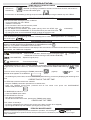
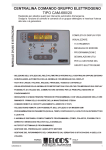
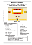
1
PANEL FOR CONTROL AND PROTECTION OF IRRIGATION MOTOR PUMPSET INTSTRUCTION AND USER MANUAL TYPE CEM-840 TYPE CEM-842 MADE TO : PROTECT motor pump sets by stopping them in the event of : - insufficient oil pressure over-temperature belt breakage minimum fuel level air filter clogging low coolant level insufficient water pump pressure DISPLAY on the panel the functions of : - hour-counter tachometer water pump pressure gauge timer fuel level gauge pump protection exclusion battery and oil lights protections intervention periodic maintenance request emergency stop Assembly on the machine and in the open air. Suitable for stopping both with solenoid valve and with electromagnet, for engines fitted with charge alternator, both with pre-excitation and with permanent magnets. BY SIMPLY STARTING, IT AUTOMATICALLY CONTROLS THE MOTOR PUMP. ALL THE OTHER FUNCTIONS ARE EASY TO USE WITH JUST THREE PUSH-BUTTONS. PARMA GB CEM-840 CEM-842 /1 ITALY 7HO )D[ (PDLOLQIR#HOFRVLW+773ZZZHOFRVLW 1 BRIEF INSTRUCTIONS AFTER STARTING, (THE ENGINE PUMP PROTECTS ITSELF AUTOMATICALLY) IT IS POSSIBLE TO ACCESS THE OTHER FUNCTIONS BY SIMPLY USING JUST THREE PUSH-BUTTONS. ACCUMULATED OPERATION HOURS ARE DISPLAYED PRESS TO SELECT THE DISPLAYED FUNCTION, EACH TIME IT IS PRESSED, THE INSTRUMENT INDICATED BY THE DISPLAY CHANGES. PRESS UNTIL THE 2 SIGNS START FLASHING TO EXCLUDE PUMP PROTECTION. TO RE-ACTIVATE PROTECTION, PRESS AGAIN UNTIL THEY SWITCH OFF. ENGINE PUMP OPERATING SPEED IS DISPLAYED THE FUEL LEVEL IS DISPLAYED PUMP PROTECTION EXCLUDED DISPLAY STOP FOR END OF WORK TIME PRESS IF YOU WANT TO SET WORKING TIME ( UP TO 24 HOURS) 24 18 6 12 TIMER IS DISPLAYED (IF SET) PUMP PROTECTION ACTIVE PERIODIC MAINTENANCE REQUEST THE WATER PUMP PRESSURE IS REGULAR EMERGENCY STOP STOPPAGE DUE TO LOW PUMP WATER PRESSURE INSUFFICIENT ENGINE OIL PRESSURE RE CON PR OLA ES EG NEVER 0 NE SIO INDICATES PUMP WATER PRESSURE MAI R THE BATTERY IS NOT CHARGING NIEEINSTELLER WENN UNTER DRUCK ENGINE PROTECTIONS ARE ACTIVE STOPPAGE DUE TO LOW FUEL LEVEL STOPPAGE DUE TO LOW LEVEL OF COOLING LIQUID STOP FOR INSUFFICIENT ENGINE OIL PRESSURE STOPPAGE DUE TO LACK OF BATTERY CHARGING (BROKEN BELT) STOP OR ONLY ALARM FOR AIR FILTER CLOGGING STOPPAGE DUE TO HIGH ENGINE TEMPERATURE STOPPAGE IN PROGRESS AUT. AVV. REGULATE WHEN UNDER PRESSURE CONTROLS MINIMUM PUMP WATER PRESSURE ENGINE PUMP START 0 OFF MANUAL STOP RESET AUT. AVV. 2 UNIT POWER SUPPLY LIGHTS CHECK ENGINE PUMP START GB CEM-840 CEM-842 /1 OPERATION START KEY 0 AUT. - OFF - MANUAL STOP - RESTORE PROTECTIONS, CANCEL PUMP PROTECTION EXCLUSION AND TIMER, DEACTIVATE INSTRUMENTS. - UNIT POWER SUPPLY - TURNS ALL THE LIGHTS ON FOR 2 SECONDS ( EFFICIENCY CHECK ) AVV. - ENGINE PUMP START OIL AND BATTERY INDICATOR LIGHTS Lit up with key on "AUT", they switch off with the engine running and regular oil pressure and battery charger system. ENGINE PROTECTION The engine protections are enabled when the ENGINE PROTECTION ACTIVE light comes on ( about 20 seconds after the end of starting impulse and however 1 minute after positioning the key on "AUT" ). Intervention of the protection probes (fitted on the engine ), indicated by the relevant lights, stops the engine, it is memorised and can be split into two groups: immediate for : delayed by 5 seconds for: - OIL PRESSURE SWITCH - AIR FILTER SWITCH - HIGH TEMPERATURE SWITCH - BATTERY CHARGER ALTERNATOR (ALTERNATOR BELT BREAKAGE) - FUEL LEVEL SWITCH - Fuel reserve flashing signal 20% (T) (WITHOUT ENGINESTOP) - Signal always on: stop for minimum fuel level (WITH ENGINE STOP) (W) - PROBE FOR COOLANT LEVEL RESET : is obtained by turning the starter key onto "ZERO" PUMP PROTECTION Pump protection is enabled when the PUMP PROTECTION ACTIVE light comes on (after 1 consecutive minute of sufficient water pressure, indicated by the PUMP PRESSURE REGULAR LIGHT and however 10 minutes after starting the engine pump). The intervention of the protection ( 5 seconds after the decrease of the pressure detected by the PUMP WATER PRESSURE SWITCH on the panel) stops the engine, it is memorised and is indicated by the INSUFFICIENT PUMP WATER PRESSURE LIGHT . (See PUMP WATER PRESSURE SWITCH ADJUSTAMENT on page 5) RESET : by turning the starter key onto "ZERO". GB CEM-840 CEM-842 /1 3 OPERATION &22/$17/(9(/352%( FOR RADIATORS WITH PLASTIC EXPANSION TANKS FOR RADIATORS WITH METAL EXPANSION TANKS :$51,1* IF THE FUNCTION /2:&22/,1* /,48,'/(9(/ IS NOT USED: CONNECT YELLOW/ ORANGE WIRE TO EARTH 155 155 SCREW ELECTRODES ROD ELECTRODE REPLACING FUSES YELLOW/ ORANGE TACHOMETER ADJUSTMENT Run the engine at a costant and known rpm value (for example by means of a portable revolution counter). Press the push-button to select the TACHOMETER instrument. The display must show a number other than zero (otherwise do not make any adjustment but check the system carefully). )86( $ Then turn the potentiometer (20 rpm maximum) inside the panel, clockwise until the display gives the right indication. (If the indication does not vary during adjustment, check system carefully.) TO REPLACES THE FUSES AND ADJUST THE TACHOMETER, REMOVE THE COVER FROM THE CENTRALIZED CONTROL PANEL AND LOOSEN THE SCREWS AT THE SIDES The unit has been designed to control stopping with an ELECTROMAGNET STOP SYSTEM SET UP To stop with the SOLENOID VALVE cut and insulate the BLUE/BROWN lead EXCITED WHILE RUNNING 85 86 30 EXCITED WHILE RUNNING (with EMERGENCY 4 button) YELLOW YELLOW STOP SYSTEMS EMERGENCY BUTTON 87 SOLENOID to close the fuel SOLENOID to close the fuel 85 86 7 4 20 7 30 WHEN THE EMERGENCY BUTTON IS MOUNTED REMOVE THE 4-20 BRIDGE (LOCATED INSIDE THE PANEL) 87 4 20 EXCITED IN STOP MODE YELLOW 85 WARNING! : IT IS NOT POSSIBLE TO MOUNT THE EMERGENCY STOP BUTTON ON A STOP SYSTEM WITH ELECTROMAGNETS 86 30 87 ELECTROMAGNET to activate the engine stop lever 2 GB CEM-840 CEM-842 /1 W I R I N G FROM 15/54 OF START KEY, USABLE FOR HEADLIGHT OR OTHERS 3A MAX * * 157 CONNECTOR CONNECTOR 3A MAX 8 7 6 5 4 3 2 1 4 2/7 4 3 2 1 INSULATE POSSIBLE CABLES NOT CONNECTED 18 40A MAX 30 50 + BATTERY 3A MAX 5 ORANGE/BLUE T INDICATOR W RESERVE 150 SKYBLUE BLACK RED 6 ORANGE GREY WHITE/RED GREEN 26/28 ORANGE/BROWN 9 :$51,1* FOR LOADS WITH CURRENT ABOVE 3A, A RELAY MUST BE USED 10 BROWN (ONLY FOR PERMANENT MAG.) WHITE YELLOW 155 * RED/GREEN YELLOW/ORANGE 11 * D I A G R A M * 40 3 41 STOP SYSTEMS SEE ON PAGE.4 CHARGE BATTERY ALTERNATOR: PRE-EXCITATION W B+ D+ 28 DO NOT USE PERMANENT MAGNETS YELLOW RED YELLOW WHITE/RED + LE GREEN 27 GRGB L C + (2/7) ELECTROMAGNET OR SOLENOID VALVE (3) OIL PRESSURE SWITCH (4) THERMOSTAT (18) FUEL FLOAT FOR INDICATOR AND RESERVE (155) COOLANT LEVEL PROBE (26) PERMANENT MAGNETS CHARGE ALTERNATOR (27) ALTERNATOR CHARGE BATTERY REGULATOR * BROWN + BATTERY R 26 WHITE/RED + BATTERY GREEN ACCESSORIES AVAILABLE ON REQUEST BROWN (28) PRE-EXCITATION CHARGE ALTERNATOR (40) STARTING MOTOR (41) BATTERY (157) GENERAL ALARM LIGHT (150) AIR FILTER CLOGGING SWITCH * 27 CONNECTION SYSTEM FOR EXTRACTING THE W TERMINAL IN PRE-EXCITATION BATTERY CHARGE ALTERNATORS. (BOSCH, MARELLI, LUCAS, ECC...) GB CEM-840 CEM-842 /1 WATER PUMP PRESSURE SWITCH REGULATION TO TACHOMETER (WHITE/RED WIRE) To diode bridge } (inside Turn the knob to a value two bar less than the pressure indicated by the pressure gauge. It is not necessary to adjust the pressure switch again if the working pressure remains constant. alternator) 5 OPERATION The push-button - exclusion is indicated by PUMP PROTECTION EXCLUSION excludes pump protection: obtained by keeping it pressed for at least 3 consecutive seconds; the function is the two intermittent lights . - this exclusion is cancelled by pressing the push-button again or by turning the starter key onto "ZERO". STOPPING THE ENGINE PUMP The unit shut down the engine in four conditions: - turning the starter key onto "ZERO" - protection intervention - timer intervention at the end of the work period - for external emergency intervention. The unit adapts to two different stop system (during which the STOP light - by working the ELECTROMAGNET for 20 seconds which pulls the STOP lever - by cutting off power to the SOLENOID VALVE shutting off the flow of fuel. is activated ): EMERGENCY STOP It can be obtained in all functioning conditions, mounting one or more release-type buttons. It is indicated by the visual signal . INSTRUMENT SELECTION The centralized control panel comprises three instruments (indicated by the relevant arrow-shaped visual signals), WHICH CAN BE SELECTED IN SEQUENCE BY PRESSING the button . Each time it is pressed IT SHOWS the next instrument. WHEN THE TIMER IS set the duration of the display of the instruments is limited to 30 seconds from the activating of the button; the TIMER then reappears. INSTRUMENTS HOURCOUNTER - Total hours of operation. With the engine running the signal indicate the correct functioning of the HOUR-COUNTER). pulsates to TACHOMETER - Speed of engine pump INDICATOR - Fuel level percentage TIMER Enabled with the key on "AUT" it makes it possible, if necessary, to have the engine pump work for an adjustable length of time ( 24 hours maximum ) , at the end of which it stops and the WORK TIME OVER sign lights up. The work time is set by pressing the TIMING push buttom desired value appears on the DISPLAY . ( lights up ) until the On releasing the push-button, the timer automatically starts working, continously displaying the remaining work time. CORRECTING OF THE SET TIME To ZERO the set time there are two methods: - keep the TIMING push-button pressed until it reaches zero; - keep the TIMING push-button pressed and at the same time press the INSTRUMENT SELECTION push-button . To INCREASE the set time: - press the TIMING push-button. To DECREASE the set time: - zero the time (see above) - set the desired value once more, pressing the TIMING button again. CANCELLING THE TIMER This is done in two ways : - by zeroing (see above) the set time (the engine pump does not have to be stopped). - by turning the starter key onto "ZERO" (the engine pump will stop). PERIODIC MAINTENANCE When it is necessary to perform the periodic maintenance operations, the visual signal lights up. The times for maintenance operations and the reset procedure (time for maintenance) can be accessed by the engine pump manufacturer. 6 GB CEM-840 CEM-842 /1 Parma (Italy) PANEL FOR CONTROL AND PROTECTION OF MOTOR PUMPSET TYPE CEM-840 CEM-842 Surveys a close-couple diesel pump while operating, commanding stopping if there are anomalies in the parts controlled by the probes. Designed to be installed also on board the machine. NOTICES Warning: adhere closely to the following advice - Always install under other equipment which produces or spreads heat. - Always follow the Wiring Diagram on page 4-5 when making connections. - Check that the line loading and the consumption of the connected equipment are compatible with the technical characteristics on page 8. - All technical interventions must be performed with the engine stationary and terminal 50 of the starter motor disconnected. - Never use a battery charger for the emergency start-up, this could damage the equipment. - To protect the safety of persons and the equipment, before connecting an external battery charger, disconnect the electrical plant terminals from the battery poles. - Do not detach the battery terminals with the close coupled pump running. THIS CONTROL PANEL IS NOT SUITABLE FOR OPERATING IN THE FOLLOWING CONDITIONS: - Where the environmental temperature is outside the limits indicated in the Technical Data on page 8. - Where there are high levels or heat from radiation caused by the sun, ovens or the like. - Where there is the risk of fire or explosions. - Where the device can receive strong vibrations or knocks. ELECTROMAGNETIC COMPATIBILITY This control panel functions correctly only if inserted in plants which conform with the CE marking standards; it meets the exemption requirements of the standard EN50082-1, but it cannot be excluded that malfunctions could occur in extreme cases due to particular situations. The installer has the task of checking that the disturbance levels are within the requirements off the standards. CONDUCTION AND MAINTENANCE The following maintenance operations should be performed every week: - check the functions of the signals; - check the condition of the batteries; - check the condition of the connectors and that they are tight. UNLESS WE MAKE A WRITTEN DECLARATION STATING THE CONTRARY, THIS CONTROL PANEL IS NOT SUITABLE FOR USE AS A CRITICAL COMPONENT IN EQUIPMENT OR PLANTS RESPONSIBLE FOR KEEPING PERSONS OR OTHER LIVING BEINGS ALIVE. YOUR ELECTRICAL TECHNICIAN CAN ASK US ANYTHING ABOUT THIS CONTROL PANEL BY TELEPHONING ONE OF OUR TECHNICIANS GB CEM-840 CEM-842 /1 7 TECHNICAL DATA 34 3 x M6 - BATTERY VOLTAGE SUPPLY - MAX CURRENT YELLOW OUTPUT (STOPPING) - MAX CURRENT RED/GREEN OUTPUT (GENERAL ALARM) - MAX CURRENT BLACK OUTPUT (STARTING) - MAX CURRENT BROWN OUTPUT (AUXILIARY) - TEMPERATURE RANGE - HOUR-COUNTER - TACHOMETER - TIMER - WATER PUMP PRESSURE GAUGE 165 85 46 DIMENSIONS 100 100 = 275 = 235 210 mm 3m - ´ *$6 ´*$6 TYPE CEM-840 CEM-842 CEM-840 CEM-842 3A 3A 40 A 3A -10 ÷ +60 °C 4 DIGITS 4000 rpm 1' ÷ 24 h 20 bar CEM-840 10 bar CEM-842 WATER PUMP PRESSURE SWITCH 4 ÷ 14 bar CEM-840 2 ÷ 5 bar CEM-842 WATER PUMP PRESSURE SWITCH DIFFERENTIAL 1 bar MAX. WATER PUMP PRESSURE 21 bar CEM-840 7 bar CEM-842 DEGREE OF PROTECTION BOX/CONNECTOR IP23/IP21 PANEL WEIGHT 3100 g TOTAL WEIGHT (PANEL + ACCESSORIES + PACKAGE) 4400 g ACCESSORIES KIT ORDERING DATA 12V 12V 24V 24V 12 or 24 V CODE 21.08.31 21.08.35 21.08.32 21.08.36 - PRE - WIRED FEMALE CONNECTOR CEM-540-840 - ELBOW GTN 6x8x1/4" GAS - NIPPLE F1/4"GAS-M3/8"GAS CODE 80.43.84 CODE 19.01.11 CODE 19.02.41 CONFORMITY DECLARATION The company Elcos s.r.l. assumes full responsibility for declaring that the equipment: type CEM-840 CEM-842 used in the ways and for the purposes described in the instruction and user manual is in conformity with the directive: - 89/336/CEE concerning electromagnetic compatibility modified by the directive 93/68/CEE because it is built and functions in accordance with the harmonized Standards EN 50081-1, EN 50082-1, EN 60529. ® 9LD1DYLJOLR$OWRD 3$50$,7$/,$ 6UO 7HO)D[ (PDLOLQIR#HOFRVLW+773ZZZHOFRVLW 8 Parma, 10/3/2000 President Walter Consigli GB CEM-840 CEM-842 /1