1
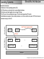
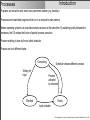
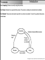
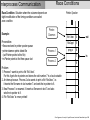
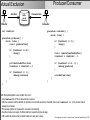
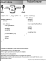
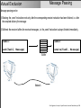
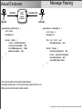
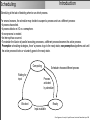
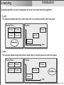
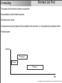
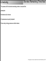
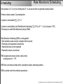
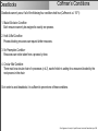
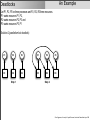
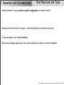
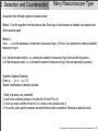
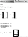
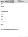
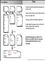
Computer Architecture and Operating Systems 1 Operating Systems Simplicity is prerequisite for reliability. (Edsger W. Dijkstra) Oliver Niggemann, University of Applied Sciences, Hochschule Ostwestfalen-Lippe, 2008 Content I. The Hardware View 1. Overview Hardware Architecture 1.1. Introduction 1.2. History 1.3. von-Neumann Architecture 2. Processor 3. Memory II. The Software View 1. Microarchitecture 2. Instruction Set Architecture (ISA) 3. Operating System 4. Assembler Language 4. Bus 5. Programming Languages (Compiler) 5. Input/Output 6. Models Physics ! Mathematics ! Oliver Niggemann, University of Applied Sciences, Hochschule Ostwestfalen-Lippe, 2009 Reference Model Software In this course, the following reference model for software will be used: Models e.g. UML, Simulink, SDL Programming Language e.g. C, C++, Java Assembler Language e.g. x86 Assembler Operating System (OS) Instruction Set Architecture (ISA) e.g. Windows, Unix, Mac OS e.g. x86 Instruction Set Microarchitecture Hardware Oliver Niggemann, University of Applied Sciences, Hochschule Ostwestfalen-Lippe, 2009 Operating Systems Introduction Content: 1. History of Unix 2. Processes 3. Inter-Process Communication 4. Scheduling 5. Deadlocks 6. Memory 7. Input and Output 8. Filesystem We will use the Minix3 operating system as an example during this course. Oliver Niggemann, University of Applied Sciences, Hochschule Ostwestfalen-Lippe, 2009 Operating Systems Introduction Content: 1. History of Unix 2. Processes 3. Inter-Process Communication 4. Scheduling 5. Deadlocks 6. Memory 7. Input and Output 8. Filesystem We will use the Minix3 operating system as an example during this course. Oliver Niggemann, University of Applied Sciences, Hochschule Ostwestfalen-Lippe, 2009 History Unix • Unix follows the KISS paradigm (Keep is simple, stupid!) • First ancestor: MULTICS (MULTI-plexed Information and Computing System) - Developed by Bell Labs, MIT and GE - Project finished only by MIT • Ken Thompson developed UNICS for PDP-7 minicomputers using assembler • Bell Labs employees tried to port UNICS to other PDP devices • Dennis Richie developed C (based on B and BCPL) to re-implement with Ken Thompson UNIX in C • The rest is history…. http://en.wikipedia.org/wiki/Image:Ken_n_dennis.jpg Oliver Niggemann, University of Applied Sciences, Hochschule Ostwestfalen-Lippe, 2009 History Unix This is where it got difficult: • AT&T (Bell’s successor) was not allowed to enter the computer business and sold UNIX to universities • AT&T developed Unix System V • 8200 LoC + 900 lines of assembler • Berkeley UNIX (Berkeley Software Distribution aka BSD) - improvements to paging and addressing, TCP/IP, … - vi, csh, … - basis for UNIX versions of SUN, DEC, … • POSIX as a way to standardize the different unix dialects • Andrew S. Tanenbaum developed MINIX for teaching purposes http://en.wikipedia.org/wiki/Image:AndrewTanenbaum.JPG Oliver Niggemann, University of Applied Sciences, Hochschule Ostwestfalen-Lippe, 2009 Unix History This is where it got interesting: • Linus Torwalds implements Linux (with MINIX as a role model) • 1991: Linux 0.0.1 - Monolithic approach aiming at the Intel 386 - V 1.0 is releases 1994 with 165000 LoC - V 2.0 is released 1996 with 470000 LoC - releases under the GPL • Linus Torwalds and Andrew Tanenbaum are well known for their different opinions about operating system design, e.g. see http://en.wikipedia.org/wiki/Tanenbaum-Torvalds_debate http://en.wikipedia.org/wiki/Image:Linus_Torvalds.jpeg Oliver Niggemann, University of Applied Sciences, Hochschule Ostwestfalen-Lippe, 2009 Linux Unix The beginning…. From: [email protected] (Linus Benedict Torvalds) Newsgroups: comp.os.minix Subject: What would you like to see most in minix? Summary: small poll for my new operating system Message-ID: <[email protected]> Date: 25 Aug 91 20:57:08 GMT Organization: University of Helsinki Hello everybody out there using minix I'm doing a (free) operating system (just a hobby, won't be big and professional like gnu) for 386(486) AT clones. This has been brewing since april, and is starting to get ready. I'd like any feedback on things people like/dislike in minix, as my OS resembles it somewhat (same physical layout of the file-system (due to practical reasons) among other things). I've currently ported bash(1.08) and gcc(1.40), and things seem to work. This implies that I'll get something practical within a few months, and I'd like to know what features most people would want. Any suggestions are welcome, but I won't promise I'll implement them :-) Linus ([email protected]) PS. Yes - it's free of any minix code, and it has a multi-threaded fs. It is NOT protable (uses 386 task switching etc), and it probably never will support anything other than AT-harddisks, as that's all I have :-(. Oliver Niggemann, University of Applied Sciences, Hochschule Ostwestfalen-Lippe, 2009 Introduction Operating Systems Different types of operating systems exist: 1. Mainframe Operating Systems - high number of parallel processes - high reliability - insurance companies, banks, airlines, …. - e.g. IBM OS/360, IBM OS/390 2. Server Operating Systems - smaller than mainframe operating systems - E.g. fileserver, printserver, www-server, … - E.g. Windows, Linux 3. Client Operating Systems - used for standard desktop PC - E.g. Windows, Linux, Mac OS 4. Embedded and Realtime Operating Systems - used for embedded devices such as mobil phones, in-car software, … - realtime requirements - optimized for platforms with small memory and processor configuration - e.g. RTAI, QNX, VxWorks, ... Oliver Niggemann, University of Applied Sciences, Hochschule Ostwestfalen-Lippe, 2009 Monolithic Architecture Operating Systems Kernel Space User Space Monolithic Architecture: • Architecture of most operating systems (OS) • All OS functions can call each other via wee-defined interfaces • All functions are linked together into one huge OS binary • The OS runs in the so-called kernel space. Only the kernel space has HW control. • Instantiated user programs, the so-called processes, run in the so-called user space. All HW and resource accesses must go via the OS. Inter-Process Communication Process 1 Process 2 …. Process n …. Function m OS Calls Function 1 Support Function 1 Function 2 …. Support Function p Hardware Oliver Niggemann, University of Applied Sciences, Hochschule Ostwestfalen-Lippe, 2009 Operating Systems Monolithic Architecture Examples: • Linux • Windows • ….. Oliver Niggemann, University of Applied Sciences, Hochschule Ostwestfalen-Lippe, 2009 Monolithic Architecture Operating Systems Example: Process calls OS function “read(fd, buffer, nbytes);” Kernel Space User Space 1. Increase SP 2. Call “ read(fd, buffer, nbytes);” 3. Push fd 4. Push buffer 5. Push nbytes 8. Call appropriate OS method id Process Library Function 6. Put Function-id for OS method “read” in register 7. TRAP and call kernel 10. Return to caller function address Dispatch Table 9. OS method “read” OS Method Hardware Oliver Niggemann, University of Applied Sciences, Hochschule Ostwestfalen-Lippe, 2009 Microkernel Architecture Operating Systems User Space Kernel Space (OS Functions) User Space Microkernel Architecture: • Kernel space is reduced to the most essential function (mainly process management) • All other OS functions work in user space Inter-Process Communication Process 1 Process 2 …. Process n IPC Inter-Process Communication Process 1 Process 2 …. Process n …. Function m OS Calls Function 1 Function 2 Hardware Oliver Niggemann, University of Applied Sciences, Hochschule Ostwestfalen-Lippe, 2009 Operating Systems Microkernel Architecture Examples: • Mach: Carnegie Mellon University, 80th • MacOS X (based on Mach) • RTOS QNX Oliver Niggemann, University of Applied Sciences, Hochschule Ostwestfalen-Lippe, 2009 POSIX Operating Systems Collection of APIs to unify the OS interface of UNIX-like operating systems POSIX comprises: • Kernel APIs • shells and utilities • conformance tests Standardized as IEEE 1003 ISO/IEC 9945 Some POSIX kernel APIs: Call pid = fork() Description create new child process s = execve(name, argv, envirop) replace process memory image fd = open(file, how, …) open file n = read(fd, buffer, nbytes); read bytes from file s = mkdir(name, mode) create directory s = mount(special, name, ag) mount filesystem s = chdir(dirname) change current directoy s = kill(pid, signal) send signal to process Oliver Niggemann, University of Applied Sciences, Hochschule Ostwestfalen-Lippe, 2009 Operating Systems Introduction Content: 1. History of Unix 2. Processes 3. Inter-Process Communication 4. Scheduling 5. Deadlocks 6. Memory 7. Input and Output 8. Filesystem We will use the Minix3 operating system as an example during this course. Oliver Niggemann, University of Applied Sciences, Hochschule Ostwestfalen-Lippe, 2009 Introduction Processes Programs are instruction sets stored on a permanent medium (e.g. harddisc). Processes are instantiated programs which run in a computer’s main memory. Modern operating systems can executed several processes at the same time. By switching quickly between the processes, the OS creates the illusion of parallel process execution. Process switching is done by the so-called scheduler. Process can be in different states: Computing Waiting for input Scheduler chooses different process Process activated by scheduler Blocked Ready Input available Oliver Niggemann, University of Applied Sciences, Hochschule Ostwestfalen-Lippe, 2009 Introduction Processes State Computing: Process is currently using the processor. State Ready: Scheduler has suspended the process. The process is waiting to be activated by the scheduler. State Blocked: The process needs some input which is currently not available. To avoid “busy waiting” the process is deactivated. Computing Waiting for input Scheduler chooses different process Process activated by scheduler Blocked Ready Input available Oliver Niggemann, University of Applied Sciences, Hochschule Ostwestfalen-Lippe, 2009 Introduction Processes Computing Waiting for input Scheduler chooses different process Process activated by scheduler Blocked Ready Input available To reactivate a process its previous state must be restored. This includes: • the program counter • all registers • status word • stack pointer • memory pointers Oliver Niggemann, University of Applied Sciences, Hochschule Ostwestfalen-Lippe, 2009 Introduction Processes Process activation and suspension: Registers PC, SC, … of Process1 are saved Registers, PC, SC, … of Process 2 are restored Process 1 Process 2 time The scheduler decides which process is when activated and deactivated. This is the so-called scheduling strategy. Oliver Niggemann, University of Applied Sciences, Hochschule Ostwestfalen-Lippe, 2009 Process Control Block Processes Each process is described by one so-called Process Control Block (PCB): Dynamic Infos Memory Management File Management Etc. Registers Pointer to Textseg. Root Direc. Priority Programm Counter Pointer to Dataseg. Working Direc. Process ID Program Status Word Pointer to Stackseg. File Descriptor Scheduling Infos Stack Pointer User-ID Parent Process Process State Group-ID Signals Starting Time Next Alarm Oliver Niggemann, University of Applied Sciences, Hochschule Ostwestfalen-Lippe, 2009 Minix 3 Example Processes src/proc.h: struct proc { struct stackframe_s p_reg; /* process' registers saved in stack frame */ … proc_nr_t p_nr; /* number of this process (for fast access) */ struct priv *p_priv; /* system privileges structure */ char p_rts_flags; /* SENDING, RECEIVING, etc. */ char p_misc_flags; /* Flags that do suspend the process */ char p_priority; char p_max_priority; char p_ticks_left; char p_quantum_size; /* current scheduling priority */ /* maximum scheduling priority */ /* number of scheduling ticks left */ /* quantum size in ticks */ struct mem_map p_memmap[NR_LOCAL_SEGS]; /* memory map (T, D, S) */ clock_t p_user_time; clock_t p_sys_time; … sigset_t p_pending; /* user time in ticks */ /* sys time in ticks */ /* bit map for pending kernel signals */ char p_name[P_NAME_LEN]; /* name of the process, including \0 */ }; Oliver Niggemann, University of Applied Sciences, Hochschule Ostwestfalen-Lippe, 2009 Processes Creating Processes Unix: 1. fork() creates a copy of the running process 2. loading of new memory image (program), e.g. by calling execve() Windows: 1. CreateProcess() creates new process and loads new program Oliver Niggemann, University of Applied Sciences, Hochschule Ostwestfalen-Lippe, 2009 Processes Processes Hierarchies Unix processes “remember” their parent process. Since all Unix operating systems first create an initial process named “init”, every Unix system is essentially a “tree” of processes with “init” being the root. “init” forks off one process for each terminal. Users can log in into each terminal. The shell process than forks off new shells for each command. Windows process are not hierarchically. Oliver Niggemann, University of Applied Sciences, Hochschule Ostwestfalen-Lippe, 2009 Processes Killing Processes Process can end in different ways: • self termination • termination by means of a serious problem • termination by operating system self termination: • Unix: call of exit() • Windows: call of exitProcess() termination by means of a serious problem: • invalid instruction • invalid memory address • division by zero termination by operating system: • Unix: kill() • Windows: TerminateProcess() Oliver Niggemann, University of Applied Sciences, Hochschule Ostwestfalen-Lippe, 2009 Threads Processes As mentioned, processes take care of resource and execution control. Sometimes closely related program modules should run in parallel, communicate with each other and use the same resources. So while execution control is needed, resource control is unnecessary and might even hinder the communication, e.g. by preventing shared memory. For such cases, threads were invented. Threads are therefore light-weighted processes which only need some execution information: Dynamic Infos Memory Management File Management Etc. Registers Pointer to Textseg. Root Direc. Priority Programm Counter Pointer to Dataseg. Working Direc. Process ID Program Status Word Pointer to Stackseg. File Descriptor Scheduling Infos Stack Pointer User-ID Parent Process Process State Group-ID Signals Starting Time Next Alarm Oliver Niggemann, University of Applied Sciences, Hochschule Ostwestfalen-Lippe, 2009 Operating Systems Introduction Content: 1. History of Unix 2. Processes 3. Inter-Process Communication 4. Scheduling 5. Deadlocks 6. Memory 7. Input and Output 8. Filesystem We will use the Minix3 operating system as an example during this course. Oliver Niggemann, University of Applied Sciences, Hochschule Ostwestfalen-Lippe, 2009 Interprocess Communication Introduction How can processes exchange information? How can the operating system prevent two processes from getting into each others way? How can the operating system coordinate depending processes? Oliver Niggemann, University of Applied Sciences, Hochschule Ostwestfalen-Lippe, 2009 Race Conditions Interprocess Communication Race Condition: Situation where the outcome depends on slight modification of the timing conditions are called race condition. Example: Precondition: • files are stored in printer spooler queue • printer daemon prints oldest file (out-Pointer points to this file) • in-Pointer points to first free queue slot Printer Spooler PrinterDaemon Process 1 file1.doc 4 file2.ppt 5 prog.c 6 7 Process 2 out in 8 Problem: 1. Process 1 wants to print a file “file3.doc”. For this it gets the in-pointer and stores the slot number 7 in a local variable 2. An interrupt occurs. Process 2 also wants to print a file “file4.doc”, i.e. it inserts the file name in slot number 7 and sets the in-pointer to 8. 3. Now Process 1 is resumed. It inserts a file name in slot 7 and also sets the in-pointer to 8. 4. File “file3.doc” is never printed! Oliver Niggemann, University of Applied Sciences, Hochschule Ostwestfalen-Lippe, 2009 Interprocess Communication Race Conditions We want to avoid such race conditions. The main idea is to forbid any situation where two process try to read and write the same memory or resource at the same time. I.e. we want to guarantee mutual exclusion for the access to shared memory. We call those section of programs that contain access to shared memory critical section. A process may only enter a critical section if no race condition can follow. To avoid race conditions, four conditions must be met: 1. No two processes may be inside their critical sections if the same shared memory is accessed inside these sections. 2. No assumptions about CPU or speed may be made. 3. Outside critical sections, no other process may be blocked. 4. No process should have to wait forever to enter a critical section. Oliver Niggemann, University of Applied Sciences, Hochschule Ostwestfalen-Lippe, 2009 Interprocess Communication Race Conditions Example for critical regions time Process A Process B A enters critical region B is blocked B tries to enter critical region A leaves critical region, B enters critical region B leaves critical region Oliver Niggemann, University of Applied Sciences, Hochschule Ostwestfalen-Lippe, 2009 Mutual Exclusion Coord. by Shared Memory One approach to handle critical regions is the synchronization via shared memory: • Disabling interrupts • Lock variables • Strict Alternation • Peterson’s solution • TSL instructions Oliver Niggemann, University of Applied Sciences, Hochschule Ostwestfalen-Lippe, 2009 Mutual Exclusion Disabling Interrupts Mutual exclusion may be achieved by disabling interrupts: • interrupts are disables after a critical region is entered • interrupts are enables when leaving the region Disadvantage: • Users must be able to disable interrupts, user could disable the whole computer for an infinite period of time • Disabling interrupts work only for one core • Approach is only used within operating systems, not by user processes Oliver Niggemann, University of Applied Sciences, Hochschule Ostwestfalen-Lippe, 2009 Lock Variables Mutual Exclusion One could think about using the following software-based solution: A global variable could be used to signal that a process enters a critical region. But reading/writing that variable could also suffer from racing conditions. Oliver Niggemann, University of Applied Sciences, Hochschule Ostwestfalen-Lippe, 2009 Mutual Exclusion Strict Alternation Another possible software-based approach is strict alternation: while (TRUE) { while (turn != 0) ; // loop critical_region(); turn = 1; noncritical_region(); } Process 0 while (TRUE) { while (turn != 1) ; // loop critical_region(); turn = 0; noncritical_region(); } Process 1 This approach has two disadvantages: First, it uses busy waiting. Locks using busy waiting approaches are called spin locks. Second, condition 3 from above is violated. E.g. process 0 might set “turn = 1” and finish its noncritical section very quickly. But if process 1 is still executing its noncritical section, process 0 can not enter its critical section, i.e. two processes are blocked in noncritical sections. Oliver Niggemann, University of Applied Sciences, Hochschule Ostwestfalen-Lippe, 2009 Peterson’s Solution Mutual Exclusion In 1981 G. L. Peterson came up with a software-based approach that does not require strict alternation: #define FALSE 0 #define TRUE 1 #define N 2 void enter_region(int processNo) { int other; int turn; int interest[N]; } other = 1 - processNo; interest[processNo] = TRUE; turn = other; while (turn == other && interest[other] == TRUE) ; // loop void leave_region(int processNo) { interest[processNo] = FALSE; } All conditions from above are met. This approach has one disadvantages: It uses busy waiting. Oliver Niggemann, University of Applied Sciences, Hochschule Ostwestfalen-Lippe, 2009 Mutual Exclusion TSL Instructions Modern processors (especially with multiple cores) have special hardware instructions to deal with locks: TSL RX, LOCK This instruction will read the word LOCK and move its value to RX. Then an nonzero value is stored on LOCK. The TSL instruction is guaranteed to be indivisible; for this the memory bus for all cores is locked. enter_region: TSL REGISTER, LOCK CMP REGISTER, #0 JNE ENTER_REGION RET leave_region: MOVE LOCK, #0 RET All conditions from above are met. The approach resembles the “lock variable” approach, but with hardware support. This approach has one disadvantages: It uses busy waiting. Oliver Niggemann, University of Applied Sciences, Hochschule Ostwestfalen-Lippe, 2009 Priority Inversion Mutual Exclusion Process A (low priority) A never gets the chance for releasing the lock Process B (high priority) B is busy waiting A enters critical region time B tries to enter critical region With priority inversion, a low priority task may effectively block a high priority tasks. Priority inversion is a consequence of the busy waiting behavior. Oliver Niggemann, University of Applied Sciences, Hochschule Ostwestfalen-Lippe, 2009 Mutual Exclusion Coord. by Sleep/Wakeup One approach to handle critical regions is the synchronization via sleep/wakeup events. Then no busy waiting is needed. Oliver Niggemann, University of Applied Sciences, Hochschule Ostwestfalen-Lippe, 2009 Producer/Consumer Mutual Exclusion Add Item Buffer with N Elements Consume Item Producter Consumer int itemCount procedure producer() { while (true) { item = produceItem() procedure consumer() { while (true) { if (itemCount == 0) { sleep() } if (itemCount == N) { sleep() } item = removeItemFromBuffer() itemCount = itemCount - 1 putItemIntoBuffer(item) itemCount = itemCount + 1 } } if (itemCount == N - 1) { wakeup(producer) } if (itemCount == 1) { wakeup(consumer) } } } consumeItem(item) With this implementation a race condition may occur: • Let itemCount be 0. This is noticed by the consumer. • After the consumer read the variable, the producer runs and adds an item into the buffer. Since now itemCount == 1, the producer tries to wakeup the consumer. • The wakeup signal is lost, because the consumer is not sleeping. • Now the consumer runs again. He thinks itemCount equals 0 and goes to sleep. • After a while the producer has produced N items and also goes to sleep. Oliver Niggemann, University of Applied Sciences, Hochschule Ostwestfalen-Lippe, 2009 Producer/Consumer Mutual Exclusion Add Item Buffer with N Elements Consume Item Producter Consumer semaphore mutex = 1, empty = N, full = 0; procedure producer() { int item; procedure consumer() { while (true) { down(full) down(mutex) while (true) { item = produceItem() item = removeItemFromBuffer() up(mutex) up(empty) down(empty) down(mutex) putItemIntoBuffer(item) } } up(mutex) up(full) } } consumeItem(item) So the problem is that wakeup signals may get lost⎯whenever some task is not asleep yet… 1965 Dijkstra suggested to to count the name of wakeup signals. For this, he suggests a special variable type for counting such events: semaphores Semaphores support two operations, up and down: up: generalization of wakeup, a process should continue to run, the semaphore value is increased by 1 down: generalization of sleep, the semaphore value is decreased by 1, if the new value will be 0, the down operation holds until an up occurs • up and down are atomic operations • • • • Oliver Niggemann, University of Applied Sciences, Hochschule Ostwestfalen-Lippe, 2009 Deadlocks Mutual Exclusion Add Item Buffer with N Elements Consume Item Producter Consumer semaphore mutex = 1, empty = N, full = 0; procedure producer() { int item; procedure consumer() { while (true) { down(full) down(mutex) while (true) { item = produceItem() item = removeItemFromBuffer() up(mutex) up(empty) down(mutex) down(empty) putItemIntoBuffer(item) } } up(mutex) up(full) } } consumeItem(item) • A deadlock could occur: If the buffer is full, empty is blocked by the producer with mutex = 0 (locked). This prevents the consumer from removing an item. I.e. both processes wait forever. • A deadlock is a situation where the compute is forced to stay forever in one state. • Working with semaphores is dangerous! Oliver Niggemann, University of Applied Sciences, Hochschule Ostwestfalen-Lippe, 2009 Message Passing Mutual Exclusion What happens, if the communication partners are not on one processor core, but e.g. are distributed over the network? TSLs, Mutexes, etc. do not work anymore… Message passing provides an answer: Tasks1: Tasks2: send(Task2, Message) receive(Task1, Message) Network Oliver Niggemann, University of Applied Sciences, Hochschule Ostwestfalen-Lippe, 2009 Message Passing Mutual Exclusion Message passing can be 1) Blocking: the „send“ instruction ends only after the corresponding receive instruction has been finished, i.e. after the complete delivery the message 2) Buffered: the receiver buffers the received messages, i.e. the „send“ instruction is always finished immediately. Tasks1: Tasks2: send(Task2, Message) receive(Task1, Message) Buffer Network Oliver Niggemann, University of Applied Sciences, Hochschule Ostwestfalen-Lippe, 2009 Message Passing Mutual Exclusion Add Item Buffer with N Elements Producter Consume Item Consumer procedure producer() { int item; message m; } procedure consumer() { int item, i; message m; while (true) { item = produceItem() receive(consumer, &m) buildMessage(&m, item) send(consumer, &m); } for (i0; i<N, i++) send(producer, &m) } while (true) { receive(producer, &m) item = extractItem(&m) send(producer, &m) consumeItem(item) } • This works for buffered and unbuffered implementations • No shared variables exists, so the mutual exclusion problem does not occur. • May take more time then shared variable solutions. Oliver Niggemann, University of Applied Sciences, Hochschule Ostwestfalen-Lippe, 2009 Mutual Exclusion The Dining Philosophers Dijkstra posed 1965 the following classical problem: n philosophers dine at an italian restaurant. Philosophers either eat or think. For eating spaghetti, each philosopher needs 2 forks. Can you write a program so that all philosophers eat and think and the program never gets stuck? http://commons.wikimedia.org/wiki/File:Dining_philosophers.png Oliver Niggemann, University of Applied Sciences, Hochschule Ostwestfalen-Lippe, 2009 Mutual Exclusion The Dining Philosophers Simple solution: #define N 5 http://commons.wikimedia.org/wiki/File:Dining_philosophers.png procedure philosopher(int i) { while (true) { think(); takeFork(i); takeFork((i+1)%N); eat(); putFork(i); putFork((i+1)%N); } } } With this implementation a deadlock may occur: • All philosopher take their left fork • All philosophers wait for the right fork⎯forever…. Oliver Niggemann, University of Applied Sciences, Hochschule Ostwestfalen-Lippe, 2009 Mutual Exclusion The Dining Philosophers Correct solution: #define N 5 Binary semaphore sem; http://commons.wikimedia.org/wiki/File:Dining_philosophers.png procedure philosopher(int i) { while (true) { think(); down(sem); takeFork(i); takeFork((i+1)%N); eat(); putFork(i); putFork((i+1)%N); up(sem); } } } With this implementation no deadlock can occur, but only one philosophers eats at one point in time…. Oliver Niggemann, University of Applied Sciences, Hochschule Ostwestfalen-Lippe, 2009 Mutual Exclusion The Dining Philosophers Correct solution: #define N 5 Binary semaphore sem = 1; http://commons.wikimedia.org/wiki/File:Dining_philosophers.png procedure philosopher(int i) { while (true) { think(); down(sem); takeFork(i); takeFork((i+1)%N); eat(); putFork(i); putFork((i+1)%N); up(sem); } } } With this implementation no deadlock can occur, but only one philosophers eats at one point in time…. Oliver Niggemann, University of Applied Sciences, Hochschule Ostwestfalen-Lippe, 2009 The Dining Philosophers Mutual Exclusion Good solution: int state[N] semaphore mutex = 1 semaphore s[N] void takeForks(i) { down(mutex) state[i] = HUNGRY test(i) up(mutex) down(s[i]) } void test(i) { if (state[i] = HUNGRY && state[LEFT] != EATING && state[RIGHT] != EATING) { } } state[i] = EATING up(&s[i]) http://commons.wikimedia.org/wiki/File:Dining_philosophers.png void philosopher(i) { while (true) { think() takeForks(i) eat() putForks(i) } } void putForks(i) { down(mutex) state[i] = THINKING test(LEFT_NEIGHBOUR) test(RIGHT_NEIGHBOUR) up(mutex) } The procedures philosopher(i)are run as separate, parallel processes. Oliver Niggemann, University of Applied Sciences, Hochschule Ostwestfalen-Lippe, 2009 Operating Systems Introduction Content: 1. History of Unix 2. Processes 3. Inter-Process Communication 4. Scheduling 5. Deadlocks 6. Memory 7. Input and Output 8. Filesystem We will use the Minix3 operating system as an example during this course. Oliver Niggemann, University of Applied Sciences, Hochschule Ostwestfalen-Lippe, 2009 Introduction Scheduling Scheduling is the task of deciding when to run which process. For several reasons, the scheduler may decide to suspend a process and run a different process: • A process has exited. • A process blocks on I/O or a semaphore. • A new process is created. • An interrupt has occurred. • To maintain the illusion of parallel executing processes, a different process becomes the active process. Preemptive scheduling strategies „force“ a process to go to the ready-state, non-preemptive algorithms wait until the active process blocks or voluntarily goes to the ready-state. Computing Waiting for input Scheduler chooses different process Process activated by scheduler Blocked Ready Input available Oliver Niggemann, University of Applied Sciences, Hochschule Ostwestfalen-Lippe, 2009 Scheduling Introduction Different applications for scheduling algorithms exist: 1. batch system - no direct user interaction - often non-preemptive strategies - few process switches higher performance 2. interactive system - Quick respond to user interactions - Illusion of parallel execution 3. real-time systems - Meeting of deadlines: hard real-time constraints: deadlines must be met under all circumstances soft real-time constraints: deadline should be met - Predicability - Avoid losing data General goals of scheduling is the maximization of throughput and CPU utilization and the minimization of turnaround times. Oliver Niggemann, University of Applied Sciences, Hochschule Ostwestfalen-Lippe, 2009 Introduction Scheduling Scheduling algorithms can also be categorized into a-priori- and online-scheduling algorithms: 1. A-priori: The Scheduler decides before the system starts when to run which process for which time period Planing Phase Runtime Process 1 Process 2 Process 3 Process 3 Process 4 Scheduler Process 2 Process 1 time 2. Online: The scheduler decides during the system‘s runtime when to run which process for which time period Planing Phase Runtime Process 1 Process 2 Process 3 Process 3 Process 4 Process 2 Process 1 Scheduler time Oliver Niggemann, University of Applied Sciences, Hochschule Ostwestfalen-Lippe, 2009 Scheduling Optimization Criteria Verzögerung, GEsamtlaufzeit, Unterbechungszeit, …. Oliver Niggemann, University of Applied Sciences, Hochschule Ostwestfalen-Lippe, 2009 Scheduling First Come ⎯ First Served Processes get processor time in the order they request the processor Non-preemptive, suited for batch processes Disadvantage: Some processes may take a long time to finish... Oliver Niggemann, University of Applied Sciences, Hochschule Ostwestfalen-Lippe, 2009 Shortest Job First Scheduling The process with the shortest runtime is executed first Non-preemptive, suited for batch processes Runtimes must be known All processes are equally important und are available at the same time, i.e. no dependencies exist between them Provable optimal process Process 2 Process 1 Process 3 time Oliver Niggemann, University of Applied Sciences, Hochschule Ostwestfalen-Lippe, 2009 Scheduling Shortest Remaining Time Next The process with the shortest remaining runtime is executed first preemptive Runtimes must be known All processes are equally important Gives newly arriving processes a better chance Oliver Niggemann, University of Applied Sciences, Hochschule Ostwestfalen-Lippe, 2009 Round Robin Scheduling Each process gets a specific quantum of running time. If it is still running after that quantum, it is preempted. Suited for interactive system The quantum lengths are decisive since switching between processes takes time process Process 2 Process 2 Process 1 Process 1 Process 3 Process 1 Process 3 time Oliver Niggemann, University of Applied Sciences, Hochschule Ostwestfalen-Lippe, 2009 Priority Scheduling Scheduling Each process gets a priority. Processes with higher priorities are executed first. Suited for interactive systems. To allow processes with lower priority to run also, priorities may be changed or maximum quantums might be assigned to high priority processes. Often priority classes are introduced; within each class a round-robin scheduling method is applied: Priority 4 Process 1 Process 2 Process 3 Priority 3 Process 4 Process 5 Process 6 Priority 2 Process 7 Process 8 Process 9 Static priority schedulers assign priorities that can not be changed during runtime, dynamic priority schedulers may change process priorities during runtime. Oliver Niggemann, University of Applied Sciences, Hochschule Ostwestfalen-Lippe, 2009 Scheduling Lottery Scheduling Each process gets a lottery ticket. Every n ms, the system chooses a ticket. The winner gets m ms of CPU time. Processes with higher priorities may get more tickets. Cooperating processes may exchange tickets. Oliver Niggemann, University of Applied Sciences, Hochschule Ostwestfalen-Lippe, 2009 Scheduling Rate Monotonic Scheduling Each process i (0 ≤ i ≤ n) has a fixed period Pi, i.e. we assume that only periodic processes exists. Process i always requires Ci processing time A system is schedulable iff ∑i Ci/Pi ≤ 1 A system is schedulable by the Rate Monotic Scheduling if ∑i Ci/Pi ≤ n(21/n - 1) (Liu & Layland, 1973). This analysis is called Rate Monotonic Analysis (RMA). Rate Monotonic Scheduling (RMS) can be applied if • Each periodic process must be complete within its period • Processes are independent of each other • Nonperiodic tasks can be neglected • Preemption causes no overhead RMS assigns each process a fixed, static priority: priority(process i) ~ 1/Pi RMS then uses these priorities within a preemptive priority scheduling schema RMS is optimal under the conditions given above. Oliver Niggemann, University of Applied Sciences, Hochschule Ostwestfalen-Lippe, 2009 Scheduling Earliest Deadline First Processes may now be aperiodic and may need different processing times within each cycle Each process i comes with a deadline ti; the deadline defines the point in time when the process must be finished. EDF Algorithm: 1. processes = {} // list of current processes 2. while (no new process appears) do 2.1. add new process i with ti to processes 2.2. take process j with tj from processes, tj is the closest deadline in processes 2.3. start process j od Oliver Niggemann, University of Applied Sciences, Hochschule Ostwestfalen-Lippe, 2009 Operating Systems Introduction Content: 1. History of Unix 2. Processes 3. Inter-Process Communication 4. Scheduling 5. Deadlocks 6. Memory 7. Input and Output 8. Filesystem Oliver Niggemann, University of Applied Sciences, Hochschule Ostwestfalen-Lippe, 2009 Introduction Deadlocks Process A (low priority) A never gets the chance for releasing the lock Process B (high priority) B is busy waiting time Example for deadlock: Priority Inversion A enters critical region B tries to enter critical region Example for deadlock: All philosophers lift their left fork at the same time Oliver Niggemann, University of Applied Sciences, Hochschule Ostwestfalen-Lippe, 2009 Deadlocks Introduction Deadlocks are created by the exclusive access of a process to a specific resource. E.g. process 1 gets exclusive access to resource 1 while process 2 gets exclusive access to resource 2. A deadlock occurs if process 1 also wants resource 2 and process 2 also wants resource 1. A resource can be a hardware device, a record in a database, shared memory, … A resource can be preemptable (e.g. shared memory) or non-preemtable (e.g. burning a cd-rom) A deadlock is defined as follows: „A set of processes is deadlocked if each process in the set is waiting for an event that only another process in the set can cause“ Oliver Niggemann, University of Applied Sciences, Hochschule Ostwestfalen-Lippe, 2009 Deadlocks Coffman‘s Conditions Deadlocks can only occur if all of the following four conditions hold true (Coffman et. al. 1971): 1. Mutual Exclusion Condition: Each resource can only be assigned to exactly one process. 2. Hold & Wait Condition: Process blocking resources can request further resources. 3. No Preemption Condition: Resources can not be taken from a process by force. 4. Circular Wait Condition: There must be a circular chain of n processes (n ≥ 2), each of which is waiting for a resources blocked by the next process in the chain So in order to avoid deadlocks, it is sufficient to prevent one of these conditions. Oliver Niggemann, University of Applied Sciences, Hochschule Ostwestfalen-Lippe, 2009 Graphical Models Deadlocks Holt invented 1972 a graphical modeling formalism for analyzing deadlock situations: P Process P R Resource R P R Resource R is blocked by process P P R Resource R is requested by process P Oliver Niggemann, University of Applied Sciences, Hochschule Ostwestfalen-Lippe, 2009 Graphical Models Deadlocks A deadlock exists if the graph contains a cycle: P1 R1 R2 P2 Oliver Niggemann, University of Applied Sciences, Hochschule Ostwestfalen-Lippe, 2009 An Example Deadlocks Let P1, P2, P3 be three processes and R1, R2, R3 three resources. P1 wants resources P1, P2, P2 wants resources P2, P3 and P3 wants resources P3, P1 Solution 1 (no parallelism): P1 P2 P3 P1 P2 P3 R1 R2 R3 R1 R2 R3 Step 1 Step 2 P1 P2 P3 R1 R2 R3 Step 3 Oliver Niggemann, University of Applied Sciences, Hochschule Ostwestfalen-Lippe, 2009 An Example Deadlocks Let P1, P2, P3 be three processes and R1, R2, R3 three resources. P1 wants resources P1, P2, P2 wants resources P2, P3 and P3 wants resources P3, P1 Solution 2 (parallelism but deadlock): P1 P2 P3 P1 P2 P3 R1 R2 R3 R1 R2 R3 Step 1 Step 2 Oliver Niggemann, University of Applied Sciences, Hochschule Ostwestfalen-Lippe, 2009 An Example Deadlocks Let P1, P2, P3 be three processes and R1, R2, R3 three resources. P1 wants resources P1, P2, P2 wants resources P2, P3 and P3 wants resources P3, P1 Solution 2 (parallelism and no deadlock): P1 P2 P3 P1 P2 P3 R1 R2 R3 R1 R2 R3 Step 1 Step 2 P1 P2 P3 P1 P2 P3 R1 R2 R3 R1 R2 R3 Step 3 Step 4 Oliver Niggemann, University of Applied Sciences, Hochschule Ostwestfalen-Lippe, 2009 Deadlocks An Example So the OS can schedule the processes by a step-by-step approach whereat before each step it is checked whether a deadlock might occur. Oliver Niggemann, University of Applied Sciences, Hochschule Ostwestfalen-Lippe, 2009 Deadlocks General Strategies There exists 4 categories of strategies to deal with deadlocks: 1. Ignore the problem 2. Detect deadlocks and „undo“ their effects 3. Avoidance of deadlocks by careful resource allocation 4. Prevention by structural negation of one of the four required conditions Oliver Niggemann, University of Applied Sciences, Hochschule Ostwestfalen-Lippe, 2009 2. Detection and Counteraction One Resource per Type Deadlock detection: Is a system with one specific configuration in a deadlock situation? Assumption here: Each resource is unique, i.e. there exists precisely one resource of each type. The resource graph is used to detect deadlocks. Resources are allocated step-by-step. Once a cycle is detected, the system can react to the deadlock. Oliver Niggemann, University of Applied Sciences, Hochschule Ostwestfalen-Lippe, 2009 2. Detection and Counteraction Many Resources per Type Assumption here: Multiple copies of a resource exists. Method 1: Use the algorithm from the previous slide. Each copy of each resource is modeled as a separat node of the resource graph. Method 2: Let p1, …, pn be the processes. Let there be ei resources of type i (1≤0<m). Let ai denote the number of available resources of type i. Let C be the allocation matrix, i.e. cij denotes the number of resources of type j that are held by process i. Let R be the request matrix, i.e. rij denotes the number of resources of type j that are requestes by process i. Algorithm: Deadlock Detection Given: p1, …, pn, e1, …, em, C, R Wanted: Identification of deadlock situation 1. Mark all process pi as „unmarked“. 2. Look for an unmarked process pi for which the i‘th row if R is ≤ A 3. If such a pi exists, add the i‘th row of C to A, mark pi and go back to step 2 4. If no such pi exists and all processes are marked there exists no deadlock. Otherwise a deadlock exists. Oliver Niggemann, University of Applied Sciences, Hochschule Ostwestfalen-Lippe, 2009 Many Resources per Type 2. Detection and Counteraction Example: E = (4 2 3 1), e.g. e0 = „cd rom“, e2 = „plotter“, ... A = (2 1 0 0) C= 0 0 1 0 2 0 0 1 0 1 2 0 R= 2 0 0 1 1 0 1 0 2 1 0 0 Step 1: p2 can be satisfied, i.e. A = (2 2 2 0) Step 2: p1 can be satisfied, i.e. A = (4 2 2 1) Step 3: p0 can be satisfied, i.e. A = (4 2 3 1) There is no deadlock What happens if R would have been like this? R = 2 0 0 1 1 0 1 0 2 1 0 1 Oliver Niggemann, University of Applied Sciences, Hochschule Ostwestfalen-Lippe, 2009 2. Detection and Counteraction Many Resources per Type Possible counteractions: 1. Preemption: A resource is temporarily given to another process This is only possible for some resource types 2. Rollback: A process‘s state is saved at some points in time, if a deadlock occurs this state is recovered. All work done since the last saving is lost. 3. Kill a process: A deadlock can be treated by killing a process. This is only in special cases a feasible solution. Oliver Niggemann, University of Applied Sciences, Hochschule Ostwestfalen-Lippe, 2009 3. Avoidance of deadlocks Save und Unsaved States Normally resources are required over time. As we have seen before, whether deadlock occur depends on the order of the resource requests and the order in which the resources are granted by the OS. We call a state safe iff if there is a scheduling order in which every process can finish even if all of them suddenly request their maximum number of resources immediately. The Banker’s algorithm (Dijkstra 1965) only grants requests that do not lead to unsafe states. The problem of this algorithm is that often it is unknown how many resources a process needs. Oliver Niggemann, University of Applied Sciences, Hochschule Ostwestfalen-Lippe, 2009 4. Structural Negation We can also negate one of the four Coffman conditions: 1. Mutual Exclusion Condition: Normally not possible; many resources (e.g. CDROM) are mutual.. 2. Hold & Wait Condition: That could be done by blocking all resources ever needed at the beginning of a process life; this is also often called two-phase locking. This is not possible for many systems because it prevents parallel process execution and often the needed resources are initially unknown. 3. No Preemption Condition: This is often not possible for many types of resources. 4. Circular Wait Condition: One approach would be to order all resources and allow processes only to allocate resources in this order. Ordering resources like this and restricting process allocation to this order is often not practical. Oliver Niggemann, University of Applied Sciences, Hochschule Ostwestfalen-Lippe, 2009 Operating Systems Introduction Content: History of Unix Processes Inter-Process Communication Scheduling Deadlocks Memory Input and Output Filesystem We will use the Minix3 operating system as an example during this course. Oliver Niggemann, University of Applied Sciences, Hochschule Ostwestfalen-Lippe, 2009 Operating Systems Memory We wil use A. Tanenbaum’s original slides: http://www.cs.rpi.edu/~hollingd/opsys/notes/Chapter3/Chapter3.pdf Please note: The content of these slides is part of this lecture and may therefore be part of the exam. Oliver Niggemann, University of Applied Sciences, Hochschule Ostwestfalen-Lippe, 2009 Operating Systems Introduction Content: 1. History of Unix 2. Processes 3. Inter-Process Communication 4. Scheduling 5. Deadlocks 6. Memory 7. Input and Output 8. Filesystem We will use the Minix3 operating system as an example during this course. Oliver Niggemann, University of Applied Sciences, Hochschule Ostwestfalen-Lippe, 2009 Operating Systems I/O I/O devices comprise • keyboard (10b/sec) • mouse (100byte/sec) • USB devices (USB2.0 60MB/sec) • DIO • PWM • ADC • SCSI (ULTRA2 80MB/sec) • PCI (528 MB/sec) • Ethernet • .... Oliver Niggemann, University of Applied Sciences, Hochschule Ostwestfalen-Lippe, 2009 I/O I/O Registers I/O device are either build into the processor or are implemented as periphery. In both cases, they are controlled via I/O registers. Oliver Niggemann, University of Applied Sciences, Hochschule Ostwestfalen-Lippe, 2009 I/O I/O Registers Example: infineon TC1797 • 180 MHZ • CAN and Flexray integrated Port 12 is a build-in, general purpose 8 bit bidirectional I/O port. It has the following registers: P12_OUT (Port 12 Output Register): offset=0000H P12_OMR (Port 12 Output Modification Register): offset=0004H P12_IOCR0 (Port 12 Input/Output Control Register 0): offset=0010H P12_IOCR4 (Port 12 Input/Output Control Register 4): offset=0014H P12_IN (Port 12 Input Register): offset=0024H P12_PDR (Port 12 Pad Driver Mode Register): offset=0040H Oliver Niggemann, University of Applied Sciences, Hochschule Ostwestfalen-Lippe, 2009 I/O I/O Registers E.g. PC12_IOCR0: “The port input/output control registers select the digital output and input driver functionality and characteristics of a GPIO port pin. Port direction (input or output), pull- up or pull-down devices for inputs, and push-pull or open-drain functionality for outputs can be selected by the corresponding bit fields PCx (x = 0-15). Each 32-bit wide port input/output control register controls four GPIO port lines: Register Pn_IOCR0 controls the Pn.[3:0] port lines Register Pn_IOCR4 controls the Pn.[7:4] port lines Register Pn_IOCR8 controls the Pn.[11:8] port lines Register Pn_IOCR12 controls the Pn.[15:12] port lines” (from TC1797_PB.pdf, TC1797 User s Manual, V1.0, Mar 2008 by infineon) Field PC0 in the register PC12_IOCR0 comprises bits 4-7 Setting these bits choses the functionality of the I/O lines: Pattern 0x0yyy: Input Pattern 0x1yyy: Output Pattern 0x0001: Input pull-down device connected Pattern 0x0010: Input pull-up device connected .... (from TC1797_PB.pdf, TC1797 User s Manual, V1.0, Mar 2008 by infineon) Oliver Niggemann, University of Applied Sciences, Hochschule Ostwestfalen-Lippe, 2009 I/O Operating Systems Four main methods exist for the communication between I/O and processor: 1. Memory-mapped I/O (MMIO) 2. Port-mapped I/O (PMIO) 3. Interrupts 4. Direct Memory Access (DMA) Furthermore, Coprocessors, signal processors, and TPUs are used. Oliver Niggemann, University of Applied Sciences, Hochschule Ostwestfalen-Lippe, 2009 I/O Operating Systems 5 main methods exist for the communication between I/O and processor: 1. Memory-mapped I/O (MMIO) • often used for microprocessors • program languages can treat I/O registers like normal memory addresses • complex wiring 2. Port-mapped I/O (PMIO) 3. Interrupts 4. Direct Memory Access (DMA) Oliver Niggemann, University of Applied Sciences, Hochschule Ostwestfalen-Lippe, 2009 MMIO I/O With MMIO, I/O registers are mapped into the normal memory. The register address is computed as: base address + register offset address Program Stack Heap Base Address I/O Registers I/O Registers Offset Address Mapping RAM Oliver Niggemann, University of Applied Sciences, Hochschule Ostwestfalen-Lippe, 2009 I/O MMIO Example: TC1797, Port 12 Pn_IOCR0 (n=12-16) Port n Input/Output Control Register 0 is mapped into address: F02F F410H + n*100H Oliver Niggemann, University of Applied Sciences, Hochschule Ostwestfalen-Lippe, 2009 MMIO I/O Example: TC1797, CAN Module • There are general control registers • Each CAN node has registers • Each message object (CAN message) has control registers (from TC1797_PB.pdf, TC1797 User’s Manual, V1.0, Mar 2008 by infineon) Oliver Niggemann, University of Applied Sciences, Hochschule Ostwestfalen-Lippe, 2009 MMIO I/O Example: TC1797, CAN Module • There are general control registers • Each CAN node has registers • Each message object (CAN message) has control registers (from TC1797_PB.pdf, TC1797 User’s Manual, V1.0, Mar 2008 by infineon) Oliver Niggemann, University of Applied Sciences, Hochschule Ostwestfalen-Lippe, 2009 MMIO I/O Example: TC1797, CAN Read 1. A message object is linked with the receiving CAN node 2. Bit MOSTATn.MSGVAL in the Message Status Register must be true (from TC1797_PB.pdf, TC1797 User’s Manual, V1.0, Mar 2008 by infineon, page 19-91) The CAN module has the base address F000 4000H Oliver Niggemann, University of Applied Sciences, Hochschule Ostwestfalen-Lippe, 2009 MMIO I/O Example: TC1797, CAN Read 1. A message object is linked with the receiving CAN node 2. Prepare message object: 2.1 Bit MOSTATn.MSGVAL in the Message Status Register must be true 2.2 Bit MOSTATn.RXEN must be true 2.3 Bit MOSTATn.DIR is equal to bit RTR of the received frame 2.4 The frame ID is set correctly Oliver Niggemann, University of Applied Sciences, Hochschule Ostwestfalen-Lippe, 2009 I/O MMIO Example: TC1797, CAN Read (from TC1797_PB.pdf, TC1797 User’s Manual, V1.0, Mar 2008 by infineon) Oliver Niggemann, University of Applied Sciences, Hochschule Ostwestfalen-Lippe, 2009 I/O Operating Systems 5 main methods exist for the communication between I/O and processor: 1. Memory-mapped I/O (MMIO) 2. Port-mapped I/O (PMIO) 3. Interrupts 4. Direct Memory Access (DMA) Oliver Niggemann, University of Applied Sciences, Hochschule Ostwestfalen-Lippe, 2009 PMIO I/O Port mapped I/O uses two different memories for program/data and for I/O registers. Often an additional signal line is used to choose the right memory. For programers, the I/O memory is addressed by means of special machine code (i.e. opcode in assembler). This method is used within most modern non-embedded processors. Program Stack Heap I/O Registers RAM I/O Memory Oliver Niggemann, University of Applied Sciences, Hochschule Ostwestfalen-Lippe, 2009 I/O PMIO Example: Intel 8086 Architecture MOV DX,442H ; load port address (I/O memory address!) OUT DX,AL ; write byte to port IN AX,DX ; read word from port Oliver Niggemann, University of Applied Sciences, Hochschule Ostwestfalen-Lippe, 2009 I/O Operating Systems 5 main methods exist for the communication between I/O and processor: 1. Memory-mapped I/O (MMIO) 2. Port-mapped I/O (PMIO) 3. Channels 4. Interrupts INT INTA 5. Direct Memory Access (DMA) InterruptController D0-D7 Prozessor Interrupt sequence: 1. I/O signals an interrupt 2. Interrupts controller decides whether signal goes to th - masking - arbitration 3. interrupt controller signals interrupt to CPU (INT signa 4. CPU signals acknowledgment (INTA signal) Niggemann, University of Applied Sciences, Hochschule Ostwestfalen-Lippe, 2009 5. InterruptOliver controller recognizes acknowledgment, D0-D Interrupts I/O INT IR0 INTA IR0 D0-D7 ... InterruptController I/O IR7 Prozessor Interrupt sequence: 1. I/O signals an interrupt 2. Interrupts controller decides whether signal goes to the CPU (e.g. interrupt suppression by means of masking) 3. Interrupt controller signals interrupt to CPU (INT signal) 4. CPU signals acknowledgment (INTA signal) 5. Interrupt controller recognizes acknowledgment, D0-D7 is used to identify the interrupt ID (IID) 6. CPU saves the PCB of the running process 7. CPU calls the computes new PC by using the IID as an index in the co-called interrupt vector table (aka dispatch table) 8. Interrupt routine is executed 9. CPU restores the PCB of the old process Oliver Niggemann, University of Applied Sciences, Hochschule Ostwestfalen-Lippe, 2009 I/O Interrupts Interrupt vector table for a x86 Linux (protected mode) 256 entries a 8 byte Physical address is stored in the processor IDT register from: Wikipedia, http:// en.wikipedia.org/ wiki/ Interrupt_vector_t able, 2010 Oliver Niggemann, University of Applied Sciences, Hochschule Ostwestfalen-Lippe, 2009 Interrupts I/O Here, we look at interrupts which as caused asynchronously from the periphery. And the focus is a programmer’s point of view; the hardware view has been discussed earlier. 1. To use an interrupt, a programmer first must make sure that the hardware generate an interrupt. E.g. for the parallel port bit 4 of I/O port 2 must be set. Then this parallel port generates an interrupt whenever the signal at pin 10 changes from low to high. 2. Most systems have a limited number of interrupts; therefore an interrupt number must be requested first. E.g. for Linux: int request_irq(unsigned int irq, // interr. no void (*handler)(int, void *, struct pt_regs *), // handling fct unsigned long flags, // guess.... const char *dev_name, // dev name void *dev_id // for shared interrupts ); void free_irq(unsigned int irq, void *dev_id); The function pointer points to the Interrupt Service Routine (ISR), the function which should be called for the interrupt. Oliver Niggemann, University of Applied Sciences, Hochschule Ostwestfalen-Lippe, 2009 I/O Interrupts 3. In the ISR, often all other interrupts should be disabled: unsigned long flags; save_flags(flags); cli(); // disable interrupts .... restore_flags(flags); ISR are not running in a process context and are therefore constraint: • They can not allocate memory. • They can not call schedule. • They can not access user space data. • They can not call wait/sleep functions Oliver Niggemann, University of Applied Sciences, Hochschule Ostwestfalen-Lippe, 2009 I/O Operating Systems 5 main methods exist for the communication between I/O and processor: 1. Memory-mapped I/O (MMIO) 2. Port-mapped I/O (PMIO) 3. Channels 4. Interrupts 5. Direct Memory Access (DMA) Oliver Niggemann, University of Applied Sciences, Hochschule Ostwestfalen-Lippe, 2009 DMA I/O Often, data is copied between I/O devices and memory. For this, the processor is not really needed. Instead a DMA controller takes care of such direct data transfer. Processor and DMA controller have to agree on the bus usage; usually the processor initiates a DMA transfer. DMA controllers an be implemented as separate chips, be part of the processor, or be part of the I/O device. Typical PCI example: Processor 1: initialize DMA transfer Northbridge RAM 3: data transfer I/O Device (e.g. HD) 4: inform about end of transfer (e.g. using an interrupt) Southbridge 2: ask for bus control Oliver Niggemann, University of Applied Sciences, Hochschule Ostwestfalen-Lippe, 2009 Introduction Operating Systems Content: 1. History of Unix 2. Processes 3. Inter-Process Communication 4. Scheduling 5. Deadlocks 6. Memory 7. Input and Output 8. Filesystem We will use the Minix3 operating system as an example during this course. Oliver Niggemann, University of Applied Sciences, Hochschule Ostwestfalen-Lippe, 2009 Operating Systems Filesystem We wil use A. Tanenbaum’s original slides: http://www.cs.rpi.edu/~hollingd/opsys/notes/Chapter4/Chapter4.pdf Please note: The content of these slides is part of this lecture and may therefore be part of the exam. Oliver Niggemann, University of Applied Sciences, Hochschule Ostwestfalen-Lippe, 2009 Computer Architecture and Operating Systems 1 Compiler Oliver Niggemann, University of Applied Sciences, Hochschule Ostwestfalen-Lippe, 2008 Content I. The Hardware View 1. Overview Hardware Architecture 1.1. Introduction 1.2. History 1.3. von-Neumann Architecture 2. Processor 3. Memory II. The Software View 1. Microarchitecture 2. Instruction Set Architecture (ISA) 3. Operating System 4. Assembler Language 4. Bus 5. Programming Languages (Compiler) 5. Input/Output 6. Models Physics ! Mathematics ! Oliver Niggemann, University of Applied Sciences, Hochschule Ostwestfalen-Lippe, 2009 Reference Model Software In this course, the following reference model for software will be used: Models e.g. UML, Simulink, SDL Programming Language e.g. C, C++, Java Assembler Language e.g. x86 Assembler Operating System (OS) Instruction Set Architecture (ISA) e.g. Windows, Unix, Mac OS e.g. x86 Instruction Set Microarchitecture Hardware Oliver Niggemann, University of Applied Sciences, Hochschule Ostwestfalen-Lippe, 2009 Compilers Disclaimer Within this lecture, no introduction to compiler theory is possible. Therefore, we wil only very briefly sketch the usage and the idea behind compilers. Everything else must be part of a specialized lecture. Oliver Niggemann, University of Applied Sciences, Hochschule Ostwestfalen-Lippe, 2009 Idea Compilers f1(); Compilers translate programming languages into machine code. f3(); f2(); f1.h #include "f1.h" #include "f3.h" f1() { ... f2(); ... } f3.h #include "f3.h" f3() { ... ... } f3.c main.h #include "main.h" #include "f1.h" main() { ... f1(); ... } The linker combines the different object files. f2() { ... f3(); ... } main.c f1.c 0x000: ... (start of f1) .... call 0x100 .... A loader takes the program, adds an offset to all memory addresses and creates the corresponding process. Compiling 0x000: ... .... .... 0x000: ... .... call _f1 ..... 0x100: ... (start of f3) ... .... 0x100: ... call _f3 Jumps to other functions in other files are done by means of symbolic links. f1.o f3.o f1.o Interpreted languages (e.g. Python, TCL, Ruby) are executed line by line; mainly by calling predefined functions for each instruction. Linking 0x000: (f1) ... .... call 0x100 ..... 0x100: (f2) ... call 0x200 .... 0x200: (f3) ... ..... 0x400: (main) ... call 0x00 i.e. _f3 = 0x200 _f1 = 0x000 a.out Oliver Niggemann, University of Applied Sciences, Hochschule Ostwestfalen-Lippe, 2009 Compilers Idea Compiling with gnu: gcc -c f1.c gcc -c f3.c gcc -c main.c Linking with gnu: gcc -o a.out f1.o f3.o main.o Oliver Niggemann, University of Applied Sciences, Hochschule Ostwestfalen-Lippe, 2009 Compilers Idea With byte code interpretation, programs are translated into an intermediate code (= byte code). The runtime environment executed one or several such byte code modules, i.e. it also handles calls between modules. Byte code programs may either be interpreted by code by byte code or just-in-time compilers are used, i.e. the byte code is translated (function by function) into machine code. Oliver Niggemann, University of Applied Sciences, Hochschule Ostwestfalen-Lippe, 2009