1
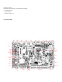
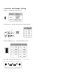
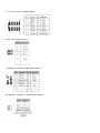
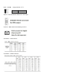
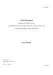
User Manual
WTM-N28 Board
supports Intel ATOM Processor
with POWER DC
/2*RTL8111E LAN/1*SATA/ 6*COM / 1*DDR3
SODIMM/1*SIM/1*MINI-PCIE/1*MINI-SATA
User Manual
Manual Rev.: 1.0
Book Number: WTM-N28-2013.03.06
User Manual
Copyright 2013
All Rights Reserved.
Manual’s first edition:
For the purpose of improving reliability, design and function, the information in this document is subject to change without
prior notice and does not represent a commitment on the part of the manufacturer.
In no event will the manufacturer be liable for direct, indirect, special, incidental, or consequential damages arising out of
the use or inability to use the product or documentation, even if advised of the possibility of such damages.
This document contains proprietary information protected by copyright. All rights are reserved. No part of this manual may
be reproduced by any mechanical, electronic, or other means in any form without prior written permission of the
manufacturer.
Trademarks
WTM-N28 is a registered trademarks of WTM; IBM PC is a registered trademark of the International Business Machines
Corporation; Pentium is a registered trademark of Intel Technologies Inc; Award is a registered trademark of Award
Software International Inc; other product names mentioned herein are used for identification purposes only and may be
trademarks and/or registered trademarks of their respective companies.
User Manual
Specifications
CPU
INTEL ® Atom Dual-Core Processor D2550 CPU (32nm,1.86GHz,1024MB L2 Cache)
Chipset
INTEL® Atom D2550/D2500 + NM10
Memory
1 * 204-pin DIMM Sockets for un-buffered Single Channel DDR3 800/1066/1333 SDRAM up to 4GB
Expansion Slots
Storage
1* Mini PCI-E socket ,1*SIM
1* Serial ATA2 3Gb/s connectors
1 * Mini-SATA connector
Audio
Realtek ALC662
Ethernet LAN
2*RTL8111E-VL LAN
LVDS
Onboard 24-bit single channel LVDS connector
USB
Embedded 8 * USB 2.0
Special Features
Intel Cedarview Processor
Support DC FAN
Support CPU Smart Fan
Rear Panel I/O
1 * DC 12V IN port
1* Power button
1 * HDMI port
1 * VGA port
2 * RJ-45 port
2 * USB 2.0 ports
1 * Audio I/O ports (Mic and Line-out )
1 * LED (Power LED and HDD LED)
Internal I/O
3* USB 2.0 ports
1 * 12V DC 4pin in
3 * NB / Chassis Fan connectors;
1 * VGA header 2*6 2.54mm
1 * AUDIO header
1* GPIO header
1* Parallel connector
1* COM3-6(RS232) connector
2* COM(RS232) connector (COM1 and COM2)
1 * MINI PCI-E connector
1 * MINI_SATA connector
1*SIM socket
1* 24-bit single channel LVDS connector
BIOS
Functional
AMI 16MB SPI Flash ROM
ATM, Automation, medical Equipment, Security, Networking, POS, General Application, Gaming
Machine, Transportation
Packing
Color Box Dimension200(W) x 200(D) x 70(H)mm
Certificate
CE, FCC, RoHS
Temperature
Operating within 0~40 centigrade (Suggest to use system FAN)
Storage within -20-85 centigrade
Form Factor
EPICForm Factor(16.5cmx11.5cm)
Package Contents
Check if the following items are included in the package.
l * WTM-N28 board
l * Quick Manual
l * Software Utility CD
Locations(TopSide)
Connector and Jumper Setting
1)JBAT :CMOS Data retention/clear
2)ATX 12V_IN:External +12V DC Power input connector
3)USB3 ,USB4(P1-3-5-7) :Internal USB2.0 connector
,
4)SATA1:SATA device connector #1
#2
#3
#4
5)VGA1:Extra VGA Signal connector
6)FP1:Front panel connector
7)AUDIO 2:5.1channels Audio signal connector
8)CHAFAN
CPUFAN:System DC fan connector
9)JP3:POWER
voltage selection(未使用)
1-2
POWER ON
2-3
POWER OFF
10)VGA:D-SUB-15 female connector for VGA output
11)LAN1:RJ45 connector for Ethernet port #1 #2
12)COM1-2:COM connector
13)COM3-6:COM3-6 connector
14)DVI1:DVI connector
15)J_HDMI1:connector
16)JP2:INVERTER
voltage selection
1-2
12V
3-4
5V
17)JP1:LCD panel driving voltage selection
18)INVERTER1:LCD panel inverter
19)LVDS1:LCD panel (Onboard 24-bit single channel LVDS )connector
BIOS SETTING
This chapter describes the BIOS menu displays and explains how to perform common tasks
needed to get the system up and running. It also gives detailed explanation of the elements found
in each of the BIOS menu displays. The following topics are covered:
Main
Advanced
Chipset
Boot
Security
Save & Exit
Once you enter
the BIOS CMOS setup utility, you can use the control keys that listed at the
bottom of the menu to select the desired value in each item.