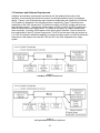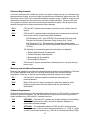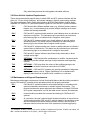
1
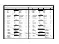
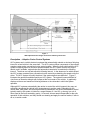
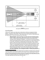
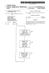
Concept of Operations and
Voluntary Operational Requirements
for
Forward Collision Warning Systems (CWS)
and
Adaptive Cruise Control (ACC) Systems
On-board Commercial Motor Vehicles
.
July 2005
Foreword
The Federal Motor Carrier Safety Administration’s (FMCSA’s) safety goal is to reduce the
number and severity of large truck fatalities and crashes. During the last several years, FMCSA
has collaborated with the trucking industry to test and evaluate several on-board safety systems
for commercial motor vehicles to increase the safety and security of all roadway users. FMCSA
is now promoting voluntary adoption of these systems within trucking fleets by initiating steps to
work closely with the trucking industry to define vendor-independent, voluntary requirements.
The purpose of this document is to relay a better understanding of the functions of on-board
safety systems for vehicle stability and to provide insight into the safety and efficiency benefits
of using the systems. This document describes the concept of operations and voluntary
requirements for Collision Warning Systems and Adaptive Cruise Control (ACC) systems for
large trucks greater than 10,000 pounds gross vehicle weight rating (GVWR). Concepts of
operations provide information about how each user interacts with these safety systems and
their operational conditions. Voluntary requirements describe features and functions used to
define the safety systems and their operational functionality. The information has been
developed in collaboration with trucking industry stakeholders, including representatives from
manufacturers, insurance companies, commercial vehicle carriers, drivers and academia.
The results from this project can be used by motor carriers as system guidelines for voluntary
adoption of on-board safety systems within their trucking fleets.
This is a final report developed under FMCSA’s deployment of on-board safety system program.
It does not supersede an earlier report on the subject.
Notice
This document is disseminated under the sponsorship of the Department of Transportation in
the interest of information exchange. The United States Government assumes no liability for its
contents or use thereof.
This report does not constitute a standard, specification, or regulation.
The United States Government does not endorse products or manufacturers. Trade or
manufacturers' names appear herein only because they are considered essential to the object
of this document.
ii
Acknowledgements
FMCSA wishes to acknowledge the efforts of those in the government, academia, research
institutions and industry who contributed their knowledge and expertise to this effort. Those
individuals include Carl Kirk and Robert Braswell of the Technology and Maintenance Council;
Marty Fletcher of US Xpress; Jim Kennedy of McKenzie Tanklines; Ron Knipling, PhD of the
Virginia Tech Transportation Institute; Scott Claffey of Great West Insurance Company; Dave
Melton of Liberty Mutual Research Institute for Safety; Anne McCartt, PhD of the Insurance
Institute for Highway Safety; Rick Craig of the Owner Operators Independent Drivers
Association; Bill Gouse of the American Trucking Associations; Tom Moses of the Spill Center;
Bob Interbitzen of the National Private Truck Council; Mike Formica and Dean Pomerleau, PhD
of Assistware; Bill Patrolia of Iteris; Meny Benady of Mobileye; Kevin Romanchok, Jim Szudy,
and Richard Beyer of Bendix; Alan Korn, Richard Romer, and Mike Lambie of Meritor WABCO;
Greg Shipman of Delphi; Tom Mattox of Eaton VORAD; Skip Yeakel of Volvo; Charlie Groeller
of Mack Trucks; Paul Menig of Freightliner; and Dan Murray of the American Transportation
Research Institute.
iii
Technical Report Documentation Page
1. Report No.
2. Government Accession No.
3. Recipient's Catalog No.
FMCSA-MCRR-05-007
4. Title and Subtitle
Concept of Operations and Voluntary Operational Requirements for Automated Cruise
Control/Collision Warning Systems (ACC/CWS) On-board Commercial Motor Vehicles
5. Report Date
July 2005
6. Performing Organization Code
7. Author(s)
Amy Houser (FMCSA), John Pierowicz (Calspan Corp.), Roger McClellan (Calspan
Corp.)
9. Performing Organization Name and Address
Calspan Corporation
4455 Genesee Street
Buffalo, NY 14225
12. Sponsoring Agency Name and Address
Federal Motor Carrier Safety Administration
Office of Research and Analysis
400 Virginia Ave. SW
Washington, DC 20024
8. Performing Organization Report No.
10. Work Unit No. (TRAIS)
11. Contract or Grant No.
DTMC75-03-F-00087
13. Type of Report and Period Covered
Technical Report – October 2003-July 2005
14. Sponsoring Agency Code
FMCSA
15. Supplementary Notes
This program was administered through the Federal Motor Carrier Safety Administration (FMCSA). The FMCSA Program Manager is Mrs.
Amy Houser.
16. Abstract
The Federal Motor Carrier Safety Administration’s (FMCSA’s) safety goal is to reduce the number and severity of large truck fatalities and
crashes. During the last several years, FMCSA has collaborated with the trucking industry to test and evaluate several on-board safety
systems for commercial motor vehicles to increase the safety and security of all roadway users. FMCSA is now promoting voluntary adoption
of these systems within trucking fleets by initiating steps to work closely with the trucking industry to define vendor-independent, voluntary
requirements.
The purpose of this document is to relay a better understanding of the functions of on-board safety systems and to provide insight into the
safety and efficiency benefits of using the systems. The information has been developed in collaboration with trucking industry stakeholders,
including representatives from manufacturers; insurance companies; commercial motor vehicle carriers; drivers; and academia.
This document describes the concept of operations and voluntary requirements for Automated Cruise Control/Collision Warning Systems
(ACC/CWS) for large trucks greater than 10,000 pounds gross vehicle weight rating (GVWR). Concepts of operations provide information
about how each user interacts with these safety systems and their operational conditions. Voluntary requirements describe features and
functions used to define the safety systems and their operational functionality.
17. Key Word
Automated Cruise Control, Collision Warning Systems, Commercial
Motor Vehicles, Heavy Trucks, Safety Systems, Tractor-Trailers,
Vehicle Stability Systems
19. Security Classif. (of this report)
Unclassified
Form DOT F 1700.7 (8-72)
18. Distribution Statement
20. Security Classif. (of this page)
Unclassified
Reproduction of completed page authorized
iv
21. No. of Pages
24
22. Price
SI* (MODERN METRIC) CONVERSION FACTORS
Symbol
in
ft
yd
mi
in2
ft2
yd2
ac
mi2
fl oz
gal
ft3
yd3
oz
lb
T
APPROXIMATE CONVERSIONS TO SI UNITS
When You Know
Multiply By
To Find
inches
feet
yards
miles
LENGTH
25.4
0.305
0.914
1.61
square inches
square feet
square yards
acres
square miles
AREA
645.2
0.093
0.836
0.405
2.59
fluid ounces
gallons
cubic feet
cubic yards
VOLUME
29.57
3.785
0.028
0.765
ounces
pounds
short tons (2000 lbs)
MASS
28.35
0.454
0.907
°F
Fahrenheit
temperature
fc
fl
foot-candles
foot-Lamberts
lbf
psi
Symbol
millimeters
meters
meters
kilometers
mm
m
m
km
mm
m
m
km
square millimeters
square meters
square meters
hectares
square kilometers
mm2
mm2
m2
m2
m2
ha
km2
m2
ha
km2
milliliters
liters
cubic meters
cubic meters
grams
kilograms
megagrams
TEMPERATURE (exact)
5(F-32)/9
Celsius
or (F-32)/1.8
temperature
ILLUMINATION
10.76
3.426
Symbol
lux
candela/m2
FORCE and PRESSURE or STRESS
pound-force
4.45
newtons
pound-force
6.89
kilopascals
per square inch
ml
l
m3
m3
g
kg
Mg
ml
l
m3
m3
g
kg
Mg
APPROXIMATE CONVERSIONS FROM SI UNITS
When You Know
Multiply By
To Find
millimeters
meters
meters
kilometers
LENGTH
0.039
3.28
1.09
0.621
inches
feet
Yards
miles
in
ft
yd
mi
square millimeters
square meters
square meters
hectares
square kilometers
AREA
0.0016
10.764
1.195
2.47
0.386
square inches
square feet
square yards
acres
square miles
in2
ft2
yd2
ac
mi2
milliliters
liters
cubic meters
cubic meters
VOLUME
0.034
0.264
35.71
1.307
fluid ounces
gallons
cubic feet
cubic yards
fl oz
gal
ft3
yd3
grams
kilograms
megagrams
MASS
0.035
2.202
1.103
ounces
pounds
short tons (2000 lbs)
oz
lb
T
°C
°C
Celsius
temperature
lx
cd/m2
lx
cd/m2
lux
candela/m2
N
N
newtons
kPa
kPa
kilopascals
* SI is the symbol for the International System of Units. Appropriate rounding should be made to comply with Section 4 of ASTM E380.
v
Symbol
TEMPERATURE (exact)
1.8 C + 32
ILLUMINATION
0.0929
0.2919
Fahrenheit
temperature
°F
foot-candles
foot-Lamberts
fc
fl
FORCE and PRESSURE or STRESS
0.225
pound-force
0.145
pound-force
per square inch
lbf
psi
1. INTRODUCTION
The Federal Motor Carrier Safety Administration’s (FMCSA’s) safety goal is to reduce the
number and severity of large truck fatalities and crashes. During the last several years, FMCSA
has collaborated with the trucking industry to test and evaluate several on-board safety systems
for commercial motor vehicles to increase the safety and security of all roadway users. FMCSA
is now promoting voluntary adoption of these systems within trucking fleets by initiating steps to
work closely with the trucking industry to define vendor-independent, voluntary requirements for
these systems.
The purpose of this document is to relay a better understanding of the functions of on-board
safety systems and to provide insight into the safety and efficiency benefits of using the
systems. The information has been developed in collaboration with expert panels consisting of
trucking industry stakeholders, including representatives from manufacturers, insurance
companies, commercial motor vehicle carriers, drivers, and academia.
This document describes the concept of operations and voluntary requirements for Forward
Collision Warning Systems (CWS) and Adaptive Cruise Control (ACC) systems for large trucks
greater than 10,000 pounds gross vehicle weight rating (GVWR). Concepts of operations
provide information about how each user interacts with these safety systems and their
operational conditions. Voluntary requirements describe features and functions used to define
the safety systems and their operational functionality.
This document discusses CWS and ACC systems provided by manufacturers, such as:
• Delphi Electronics and Safety
• Eaton VORAD
• Mobileye
Descriptions of these currently available systems are in Appendix A. United States Department
of Transportation (USDOT) websites that contain further information on governmental research,
testing and evaluation of CWS and ACC systems include:
www.its.dot.gov/ivi/ivi.htm
www.fmcsa.dot.gov/safetyprogs/research/researchpubs.htm
2. CONCEPT OF OPERATIONS
Description – Forward Collision Warning Systems
CWS are in-vehicle electronic systems that monitor the roadway in front of the host vehicle and
warn the driver when a potential collision risk exists. For example, currently available radarbased CWS use algorithms to interpret transmitted and received radar signals to determine
distance, azimuth, and relative speed between the host vehicle with the CWS and the vehicle or
object ahead of it in the lane. When the host vehicle is traveling along the roadway, the CWS
can warn the driver when a vehicle or object is in its lane within a predefined closing time
threshold. Currently, CWS do not take any automatic action to avoid a collision or to control the
vehicle; therefore, drivers remain responsible for the safe operation of their vehicles using both
steering and braking, if safe to do so, to avoid a crash. As the time interval to the vehicle ahead
decreases, CWS issue a progressively more urgent warning. The system’s beam width/field of
view forms an isosceles triangle with its apex at the front center of the vehicle. As an object gets
closer to the front of the vehicle, a different range or time interval is reached, and the system
issues a different type of alarm. The system manufacturers set these warning thresholds.
Figure 1 illustrates these progressive thresholds. CWS also warn the driver if the system
malfunctions. CWS may be integrated with ACC systems.
1
Figure 1
CWS Object Detection Ranges and Collision Warning Thresholds
Description – Adaptive Cruise Control Systems
ACC systems are in-vehicle electronic systems that automatically maintain a minimum following
interval to a lead vehicle in the same lane. The ACC system utilizes components of the collision
warning system and a conventional cruise control system. When the host vehicle with the ACC
system is traveling above a minimum speed threshold, the ACC system controls the engine
throttle, and if available, engine brake and automatic transmission to maintain the following
interval. The driver can set and adjust his following interval. In the absence of a vehicle ahead,
the ACC system operates like a conventional cruise control by maintaining the speed set by the
driver. The ACC system will notify the driver if the system detects a malfunction. Figure 2
illustrates the general thresholds used by an ACC system. The system's beam width/field of
view forms an isosceles triangle with its apex at the front center of the vehicle. It graphically
displays minimum and maximum following distance or time intervals in which the system
operates.
Although ACC systems automatically take action to control the vehicle’s speed, they may not
sufficiently decelerate the vehicle in all circumstances to avoid a crash. Depending on the
vehicle load, road grade, and vehicle performance parameters, the level of deceleration control
typically used by the system is limited to a range between 0.1 and 0.2 g, where g is a unit of
force equal to the force exerted by gravity. As a result, drivers remain responsible for the safe
operation of their vehicles, and they should use steering and apply the service brakes, if safe to
do so, to avoid a crash.
3
Figure 2
ACC System Vehicle Following Intervals
Crash Prevention
CWS and ACC systems can help reduce crashes when vehicles are equipped with these
systems. In particular, these systems may prevent rear-end crashes and forward impact
crashes with objects in the travel lane. These systems may also reduce the impact speed and
the crash severity. This section describes these crash types.
•
Rear-end Crash – Rear-end crashes occur when the front of a following vehicle
strikes the rear of a lead vehicle. Data derived from the 2003 General Estimates
System 1 (GES) indicates that 42,800 rear-end crashes involving large trucks
occurred in 2003, resulting in 290 fatalities. “In 18 percent of all rear-end crashes
where the truck was the striking vehicle, there were three or more vehicles involved
in the crash. The difference is even greater in fatal rear-end crashes. Almost 46
percent of fatal rear-end truck-striking crashes involved three or more vehicles,
while only 16 percent of fatal truck-struck rear-end crashes involved three or more
vehicles. The large difference between the mass of trucks and the mass of other
vehicles may explain this phenomenon. A typical loaded tractor semi-trailer has a
gross weight of 80,000 pounds, while most cars weigh less than 4,000 pounds.
Striking a passenger vehicle in the rear will not bring a heavy truck to a stop or
even slow it appreciably. Thus, the impact itself does relatively little to keep the
truck from continuing on and involving other vehicles.” 2 CWS can reduce the risk of
1
The General Estimates System is directed by the National Center for Statistics and Analysis, which is a component
of The Office of Research and Development in NHTSA. Data for GES come from a nationally representative sample
of police reported motor vehicle crashes of all types, from minor to fatal. The system began operation in 1988, and
was created to identify traffic safety problem areas, provide a basis for regulatory and consumer initiatives, and form
the basis for cost and benefit analyses of traffic safety initiatives. The information is used to estimate how many motor
vehicle crashes of different kinds take place, and what happens when they occur.
2
Craft, Ralph. FMCSA Paper: Rear-End Large Truck Crashes, 2002.
4
these rear-end crashes by identifying fast closing situations and providing the
driver with additional time to react. ACC systems function to maintain a driver-set
following interval behind another vehicle, thereby providing more time to resolve
driving conflicts to reduce the probability of a rear-end collision.
•
Forward Impact with Objects in Travel Lanes – These crashes occur when a
vehicle strikes an object that is in the vehicle’s travel lane. Data from the 2003
GES indicates that large trucks were involved in 18,000 crashes of this type in
2003, resulting in 160 fatalities. CWS can reduce the risk of these crashes by
warning the driver of the presence of these objects, thereby allowing them
additional time to take the appropriate avoidance maneuvers.
Additional benefits of ACC systems and CWS may include the reduction of hard braking events.
Operations and Users
This section describes how drivers, fleet managers, and fleet maintenance personnel interact
with CWS and ACC systems and potential benefits that each stakeholder may realize with these
systems.
The commercial vehicle population is comprised of a wide variety of vehicle types and uses. At
a high level, two types of vehicles are predominant, combination vehicles (tractors-trailers) and
straight trucks. These two types of vehicles have very different operating characteristics. In
general, straight trucks tend to be used in a more local setting, used to provide deliveries of
goods and services to customers generally within a 50 to 100 mile radius of their base of
operations, while combination vehicles are more often utilized in regional and long distance
applications. Combination vehicles account for about 30% of total commercial vehicles, but
65% of the commercial vehicle miles traveled. Due to their high mileage exposure and severity
of crashes, combination-unit trucks have the highest crash cost per vehicle over the operational
life of the vehicle. 3 Therefore, CWS may provide a relatively higher safety benefit for operators
of this class of trucks.
The trucking industry is actually a broad collection of many industries, each with operating
characteristics as diverse as the industries they service. Segmentation of the trucking industry is
often based on the size of fleets, the geographic range of its operations, and the commodities
hauled. Usually one characteristic is not adequate to describe a particular segment, but rather
combinations of characteristics are required to best describe operations. For example, there
may be a trucking firm with a large fleet providing package delivery type service to a relatively
small geographic area, while there may be a single truck company that provides general freight
services to all states in the continental United States.
The movement of goods by truck is conducted on all types of roads, at all hours of the day, and
in all types of driving conditions. Since collisions with other vehicles or obstacles can occur
along any route, many fleet types may benefit from using CWS, yet they may be most promising
for trucks with high mileage accumulated over their operational life or that operate under
conditions that may present driving challenges such as nighttime or limited visibility due to
weather. Also, currently, CWS operate at any vehicle speed. ACC systems only operate above
a specified minimum vehicle speed, which typically limits the systems’ use to roadways where
drivers travel at or above this minimum speed in accordance with the posted speed limits. The
application of these systems to specific fleets may be determined by the amount of time the
fleet’s vehicles operate in these roadway types.
3
Wang, J.S.; Knipling, R.R.; and Blincoe, L.J. The dimensions of motor vehicle crash risk. Journal of Transportation
and Statistics. Volume 2, No. 1, pp. 19-43, ISSN 1094-8848, May 1999.
5
Drivers
Drivers are the primary CWS and ACC system users, as described in the following daily
operational scenarios:
Normal system startup operation – When the driver turns the ignition switch to start the
vehicle, CWS and ACC systems perform a power-up self-test. The driver scans the warning
indicators to determine any system malfunctions. If necessary, the driver may alert fleet
maintenance personnel for corrective action. A driver can scan the CWS or ACC system
status indicator to verify that the system operation has commenced.
System fault conditions – If a system fault occurs or the system cannot detect vehicles
ahead or control the speed of the host vehicle, the driver is provided with a message via the
system status indicator. Some CWS and ACC systems may display warning indicators
relating to specific faults or other detected conditions.
Progressive CWS warning/alert situations – When traveling at or above the minimum
CWS detection speed, the host vehicle will encounter other vehicles ahead within the travel
lane. As the host vehicle approaches the vehicle ahead, the CWS may provide a series of
progressive alerts to the driver. These progressive alerts indicate that the following interval
is decreasing and the driver should take action. These progressive warnings can escalate
from audio tone only to audio, visual, or other warning modes.
ACC system operation – ACC systems automatically maintain a minimum following interval
between the driver’s vehicle and the vehicle ahead of it. When no vehicle is present in front
of the vehicle with the ACC system, the ACC system maintains the speed set by the driver
as in current cruise controls. The system has a self-diagnosis mode that can detect system
faults. If the system is active when a fault is detected, the ACC system reverts to manual
throttle control.
On-road use of CWS and ACC systems – A driver may encounter several types of
roadways where these systems provide a potential benefit. Yet, some systems may have
limitations, including false positive indications, such as the identification of signs, barrels,
and other roadside objects that may not be actual obstacles in the travel lane.
Divided highways and interstates/Straight and large radius curved flat roads –
“Trucks Involved in Fatal Accidents (TIFA) and GES data show that rear-end truck
crashes are more likely to occur on divided roadways and interstate highways–
overlapping categories–than other truck crashes. With regard to fatal crashes, 58
percent of truck striking crashes occurred on interstate highways, as opposed to 19
percent of all truck fatal crashes. 4 ” These road types are where CWS and ACC systems
could provide the greatest benefit. While the vehicle is operating on these roads, CWS
can detect vehicles ahead and issue warnings to the driver when it detects an excessive
closing speed condition. ACC systems will control the speed of the host vehicle and
interval to the lead vehicle.
Two-way roads with sharp curves – CWS and ACC systems could have limited
azimuthal coverage to the front of the vehicle. When the host vehicle is traversing sharp
curves, the lead vehicles may no longer be in the range of the host vehicle’s sensor
coverage area. When these situations arise, each system has a different means of
accommodating the loss of detecting the lead vehicle. CWS may not re-detect the lead
vehicle until the host vehicle enters the curve. The ACC system will revert to
4
Craft, Ralph. FMCSA Paper Rear-End Large Truck Crashes.
6
conventional cruise control by maintaining the current set speed until the lead vehicle is
detected again. When the lead vehicle is detected, the ACC system will revert to the set
following interval.
Roads with hills and valleys – CWS may produce false positive indications when the
host vehicle is on a roadway with major changes in elevation. When a host vehicle is
traveling up a hill, current CWS may detect objects such as overhead signs. Other
roadway features that could cause loss of vehicle tracking or false alarms include dips in
the roadway and hillcrests.
Fleet Management
Fleet managers are responsible for all administrative, financial, and operational aspects of the
fleet. Safety officers focus on the fleet’s operational safety issues and examine the safety
aspects of the fleet’s vehicles in accordance with USDOT safety regulations. They also work
with drivers to provide safety and operational training, verify that drivers are complying with
safety regulations, and examine how well drivers operate their vehicles (e.g., logging accidents,
traffic infractions, etc.).
These personnel examine various types of available safety equipment, evaluate the equipment,
justify the purchase of all equipment, determine the overall effectiveness of this equipment, and
calculate the return on investment (ROI) for their fleet. They work with the maintenance
department and drivers to explain CWS and ACC system benefits. CWS and ACC systems
may have the capability to store operational data internally for retrieval by the fleet. This data
may be useful in reconstructing an accident or as training feedback in analyzing a driver’s
performance. Fleet managers may obtain operational data (e.g., number of hard-braking
events) from CWS and ACC systems via the in-vehicle network and analyze the data to
determine any systemic problems with their fleet operations (e.g., disproportionate number of
close-following events with certain drivers, high number of hard-braking events on certain
routes). These in-vehicle networks provide a data “backbone” to the truck, permitting the
sharing of various system level data, such as engine and transmission performance. Research
has indicated that the monitoring of driver behavior can have a positive effect on driver and fleet
safety. 5
Maintenance Management and Installation
Maintenance managers and service technicians are responsible for the proper functioning of all
equipment installed on the fleet’s vehicles and for installing and maintaining CWS and ACC
systems on the fleet. The maintenance managers support fleet operations by maintaining CWS
and ACC systems. They acquire and relay operational and reliability data to the fleet managers
and work with suppliers to resolve any problems encountered with system use.
CWS and ACC systems have different installation requirements for each vehicle type and
model. Depending on the system, CWS and ACC systems may be installed by a truck original
equipment manufacturer (OEM) or as an aftermarket accessory by the fleet or other service
personnel. When installed by a truck OEM, the CWS and ACC system component locations
and mounting methods are identical for each vehicle model. The OEM provides dedicated
wiring harnesses for the connection between the CWS and ACC systems and the vehicle.
When installed as an aftermarket accessory, CWS and ACC systems’ components should be in
5
Knipling, R.R.; Boyle, L.N.; Hickman, J.S.; York, J.S. Daecher; C., Olson, E.C.B.; and Prailey, T.D. Synthesis
Report # 4: Individual Differences and the High-Risk Commercial Driver. Project Final Report, Transportation
Research Board Commercial Truck and Bus Synthesis Program. ISSN 1544-6808, ISSN 0-309-08810-0,
available at http://trb.org/news/blurb_browse.asp?id=11, 2004
7
the proper locations and orientations as described in the installation manual with the key
parameters entered into the system. Furthermore, the systems will require periodic
maintenance, particularly in the area of component (e.g., radar, camera, antennae) alignment.
3. VOLUNTARY REQUIREMENTS
The voluntary requirements included in the following sections define fundamental CWS and
ACC system features and the ability of the systems to withstand the electrical and
environmental extremes commonly found on commercial vehicles.
The types of voluntary requirements for CWS include:
1. Functional Requirements
2. Data
3. Hardware and Software Requirements
4. Driver Vehicle Interface (DVI) Requirements
5. Maintenance and Support Requirements
CWS and ACC system manufacturers may include additional functions to augment system
capability and features that may be useful beyond minimum system functionality; the operational
features that fall into this category are labeled with the term “OPTIONAL”. However, in all
cases, CWS and ACC systems must comply with all existing FMCSA Safety Regulations. The
requirements numbering system designates defining requirements with an “R” and optional
features with a “T”.
3.1 Functional Requirements
Functional requirements refer to basic system functionality and operation of CWS and ACC
systems.
R1-1
CWS and ACC systems should perform a self-test that checks all major
system sensors and components and operate within 30 seconds of starting
the vehicle. System status results should be provided to the driver within the
30 seconds time interval.
R1-2
CWS should detect, track, and issue warnings for the following potential precollision conditions based on following interval thresholds when the functional
requirements R1-3 and R1-4 are met:
•
Host vehicle closing on a lead vehicle with constant velocity
•
Host vehicle closing on a lead vehicle that is accelerating
•
Host vehicle closing on a lead vehicle with both vehicles decelerating
•
Host vehicle closing on a lead vehicle preceded by a lane change
•
Host vehicle closing on a stopped lead vehicle
•
Host vehicle closing at a constant speed on a decelerating lead
vehicle
•
Host vehicle closing on a stationary object in the roadway
8
R1-3
CWS and ACC systems should be capable of detecting a vehicle in the travel
lane of the vehicles with the CWS and ACC systems to a distance of up to
100 meters (328 feet) on straight roads and on curves with radius greater
than 500 meters (1640 feet).
R1-4
CWS and ACC systems should be capable of differentiating between
oncoming traffic on two-way curved roadways and vehicles in the travel lane
of the vehicles with the CWS and ACC systems.
R1-5
CWS and ACC systems should function under all potential weather
conditions such as clear weather, rain, snow, fog, or combinations of these
conditions. If the system cannot function in these conditions, the driver
should be provided with a clear indication that the system is not functioning.
R1-6
CWS and ACC systems should be capable of differentiating stationary
roadside objects such as guardrails, signs, and bridges from moving vehicles
in both the travel lane and opposing lanes of the vehicles with the CWS and
ACC systems.
R1-7
If CWS and ACC systems engage the vehicle’s service brakes, the vehicles
brake lights should be activated in compliance with Federal Motor Vehicle
Safety Standard 108.
R1-8
CWS should use progressive warnings to provide the driver with sufficient
time to avoid forward crashes.
T1-1
OPTIONAL – CWS may interact with an ACC system to maintain a safe
following interval to the vehicle ahead.
T1-2
OPTIONAL – CWS may issue proximity warnings when the host vehicle is
slowly moving forward (less than 2 mph) towards a stationary object or if an
object ahead is slowly rolling towards the front of the host vehicle.
3.2 Data
This section defines the format of data generated by or can be obtained directly in real-time
from CWS and ACC systems. Two Society of Automotive Engineers (SAE) standards specify
in-vehicle data communication in heavy trucks:
•
SAE J1587, “Electronic Data Interchange between Microcomputer Systems in HeavyDuty Vehicle Applications” (message definition for the J1708 data bus), or
•
SAE J1939-71, “Recommended Practice for Control and Communications Network for
On-Highway Equipment – Vehicle Application Layer”
Although neither of these standards defines CWS messages, it would be beneficial if CWS
suppliers adopt a common set of standard CWS messages. Drivers and fleet managers could
obtain these CWS messages via the in-vehicle data network. SAE J1939-71 already defines
the data available from ACC systems via the on-board diagnostic (OBD) connector.
T2-1
OPTIONAL – ACC systems may issue various data messages about the
operating states and modes of the system on the in-vehicle data network,
which may be custom messages or as defined by SAE standard J1939 6 .
T2-2
OPTIONAL – CWS and ACC systems may have the capability to store
operational data for providing driving feedback to drivers.
6
Heavy trucks may have either or both J1708 and J1939 networks. J1708 (J1587) is typically more easily accessible
by the fleet, and J1939 is typically reserved for high-priority engine-transmission control data. However, CWS may
interface with either or both networks. See Section 4.4 for a listing of CWS’ network messages.
9
3.3 Hardware and Software Requirements
Hardware and software requirements deal directly with the detailed functionality of the
hardware, environmental and electrical concerns, mounting/installation issues, and software
design. Figures 3 and 4 illustrate the major functional components and interfaces of CWS and
ACC systems as described in the following sections, respectively. Figure 3 shows the interrelationship of the CWS components. The electronic control unit (ECU) accepts data from the
forward-looking sensor. Through the vehicle network (J1708 or J1939), the ECU monitors the
brake activation status and engine power. The output of the system is a status indicator and,
when necessary, a warning, which appear on the driver-vehicle interface. Figure 4 shows the
inter-relationship of the ACC system components. The ECU has the same input and outputs as
in a CWS, but it has the additional capability to control the engine speed or to shift the automatic
transmission. Both figures show that the CWS and ACC are often integrated into a single
system.
Figure 3
CWS Major Functional Components
Figure 4
ACC System Major Functional Components
10
Typical System Hardware
This section describes the functionality of the primary physical components of CWS and ACC
systems. They refer to the functional blocks shown in Figures 3 and 4.
R3-1
Forward-looking Sensor or Detector – CWS and ACC systems should
have a sensor or apparatus that detects vehicles in the front of the host
vehicle. This sensor or apparatus should be capable of determining the
distance and location of moving or stationary vehicles in the travel lane of the
host vehicle. CWS and ACC systems should be capable of detecting moving
or stationary vehicles to at least 100 meters (328 feet) ahead of the vehicle.
R3-4
Electronic Control Unit (ECU) – The CWS and ACC systems’ ECU should
be used to gather data for calculating key parameters to provide warnings.
For the ACC system, the ECU should be capable of controlling the engine
speed or shifting the automatic transmission.
R3-2
Driver Vehicle Interface – CWS and ACC systems should provide a driver
vehicle interface (DVI) to permit the driver to interact with the systems. A DVI
consists of controls and indicators for CWS and ACC systems related to the
system operation. The DVI includes progressive audible and visual warnings
of a potential collision threat to the host vehicle. CWS and ACC systems
should provide a visual indication of the status of the systems. System status
includes operational/non-operational, tracking/not-tracking, and system fault
conditions. See Section 3.4 for complete DVI requirements.
T3-1
OPTIONAL – Adaptive Cruise Control – CWS may interact with an ACC
system to maintain a safe following interval between the host vehicle and the
vehicle in front of it.
T3-2
OPTIONAL – Vehicle Network – CWS and ACC systems may use the invehicle data network (SAE J1708 or J1939) for data communication to data
recording or diagnostic devices.
Environmental Requirements
The environmental conditions that exist in heavy trucks are very severe. The SAE has
developed a comprehensive standard that describes various aspects of the heavy truck
environment in its J1455 standard. The standard also includes procedures that are used to
verify system compliance.
R3-3
CWS and ACC systems should meet the environmental requirements as
stated in the most recent version of the following SAE standard:
SAE Standard J1455, “Joint SAE/Technology and Maintenance Council
(TMC) Recommended Environmental Practices for Electronic Equipment
Design (Heavy-Duty Trucks)”.
The following environmental aspects are covered by the standard:
•
•
•
•
•
•
•
•
•
•
Altitude
Fungus
Mechanical Shock
Mechanical Vibration
Relative Humidity
11
Temperature
Salt Spray Atmosphere
Immersion and Splash
Steam Cleaning and Pressure Washing
Dust, Sand, and Gravel Bombardment
Electrical Requirements
In a truck’s electrical power distribution system, the system voltage may vary, the alternator may
generate electrical noise, and various types of transients may momentarily place more than 100
volts direct current (VDC) on the electrical distribution system’s wiring. In addition, there may be
electrostatic discharge into the system from a buildup of static electricity. Because CWS and
ACC systems connect to the truck’s electrical power distribution system, they should function
normally throughout all of these perturbations without damage.
R3-4
CWS and ACC system power should be derived from the vehicle electrical
system.
R3-5
CWS and ACC systems should meet the electrical requirements as stated in
most current version of the following SAE standards:
SAE Standard J1455, “Joint SAE/TMC Recommended Environmental
Practices for Electronic Equipment Design (Heavy-Duty Trucks)”.
SAE Standard J1113, “Electromagnetic Compatibility Measurement
Procedures and Limits for Vehicle Components (Except Aircraft) (60 Hz to
18 GHz)”.
The following environmental aspects are covered by the standards:
• Steady State Electrical Characteristics
• Transient Electrical Characteristics
• Electromagnetic Susceptibility
• Electromagnetic Emission
R3-6
CWS and ACC system data should not be destroyed nor corrupted during a
power surge.
Mounting and Installation Requirements
Mounting and installation requirements include all aspects related to the installation of CWS and
ACC system hardware onto the truck, including the mounting of the individual system
components. There are no specific requirements pertaining to system size or weight.
R3-7
CWS and ACC systems should be installed per manufacturer’s
recommendations.
R3-8
Major CWS and ACC system components, other than cabling or small
mounting components, should be marked with the manufacturer’s
identification.
Software Requirements
Software requirements refer to the embedded software that runs in CWS and ACC systems and
controls all system functionality. The microcontroller or microprocessor continuously runs the
system software when CWS and ACC systems are active.
T3-3
OPTIONAL – CWS and ACC systems may include software for downloading
ASCII data files that can be easily read into a statistical, database, or
spreadsheet software package.
T3-4
OPTIONAL – The embedded software of CWS and ACC systems can be
field upgradeable via the in-vehicle network connection (i.e., J1587 or J1939)
or other common data interface (e.g., RS-232 or Universal Serial Bus (USB)).
12
Only authorized personnel should upgrade embedded software.
3.4 Driver-Vehicle Interface Requirements
These requirements define specific ways in which CWS and ACC systems interface with the
driver (i.e., Driver-Vehicle Interface), and include indicators, displays, and warning methods.
The National Highway Traffic Safety Administration (NHTSA) Federal Motor Vehicle Safety
Standard 101 (FMVSS 101) should be used as a guide for CWS and ACC system indicators.
R4-1
CWS should utilize different audible tones (e.g., different pitches, patterns,
lengths, etc.) or tactile warnings to provide multiple warnings as an object
crosses the warning thresholds.
R4-2
CWS and ACC systems should include a visual indicator when no vehicles or
objects are in the lane. The indication may be provided by an instrument
panel warning light or an indicator that is integral to each system.
R4-3
CWS and ACC systems should use a visual indicator to provide system
operational status. This status may be indicated by an instrument panel
warning light or an indicator that is integral to each system.
R4-4
CWS and ACC systems should use a visual or audible indicator to indicate a
system failure or malfunction. This status may be indicated by an instrument
panel warning light or an indicator that is integral to the system.
R4-5
CWS and ACC system indicators should be clearly discernable in direct
sunlight and at night.
T4-1
OPTIONAL – CWS should utilize combinations of audible, visual and tactile
indicators to provide multiple warnings of object detection and impending
collision.
T4-2
OPTIONAL – CWS may allow the volume of the audible warnings to be
adjusted, but not below a minimum sound level of 65 dBA 7 .
T4-3
OPTIONAL – CWS and ACC systems may provide operational or diagnostic
messages or codes, such as “System Operational” on an alphanumeric
display to alert the driver of specific faults, conditions, or concerns.
3.5 Maintenance and Support Requirements
Maintenance and support requirements include functionality/features that should be provided to
ensure CWS and ACC systems will be operated correctly and properly maintained.
R5-1
CWS and ACC systems should be serviced periodically in accordance with
system maintenance instructions to maintain system functionality. This
process maintains the proper alignment and calibration of integral CWS and
ACC system components, such as the radar sensor, camera, and antennae.
R5-2
Users should be provided with a manual and training for CWS and ACC
systems.
R5-3
At a minimum, the user’s manual should include information on the minimum
vehicle speed at which CWS and ACC systems operate, the conditions under
which the systems can/cannot detect and track vehicles, and the types of
indicators used to inform the driver if the systems are functioning properly.
7
For reference: 90 dBA = heavy truck at 10m, 80 dBA = curbside of busy street, 70 dBA = car interior, 60
dBA = normal conversation at 1m (3.28 ft.), and 50 dBA = office noise.
13
R5-4
Manufacturers should provide product support for users and fleets to ask
questions regarding capabilities and resolve problems with systems.
T5-1
OPTIONAL – Video, audio, or computer-based training material may be
provided for fleet management and/or drivers.
T5-2
OPTIONAL – CWS and ACC systems may be transferable from one vehicle
to another. System recalibration and/or resetting of system parameters
should be performed when the system(s) are moved between vehicles.
14
4. ACRONYMS
Acronym
Definition
ACC
Adaptive Cruise Control
ASCII
American Standard Code for Information Exchange
COTS
Commercial Off-The-Shelf
CWS
(Forward) Collision Warning System(s)
DVI
Driver-Vehicle Interface
ECU
Electronic Control Unit
EV
Eaton VORAD
FMCSA
Federal Motor Carrier Safety Administration
FMVSS
Federal Motor Vehicle Safety Standard
GES
General Estimates System
GVWR
Gross Vehicle Weight Rating
kph
Kilometers per Hour
mph
Miles per Hour
NHTSA
National Highway Traffic Safety Administration
OBD
On-Board Diagnostic
OEM
Original Equipment Manufacturer
ROI
Return on Investment
SAE
Society of Automotive Engineers
TIFA
Trucks Involved in Fatal Accidents
TMC
Technology and Maintenance Council
USB
Universal Serial Bus
USDOT
United States Department of Transportation
VDC
Volts Direct Current
15
5. REFERENCES
Craft, Ralph. FMCSA Paper Rear-End Large Truck Crashes. http:/www.fmcsa.dot.gov/factsresearch/briefs/rear.pdf, 2002.
SAE Standard J1113, “Electromagnetic Compatibility Measurement Procedures and Limits
for Vehicle Components (Except Aircraft) (60 Hz to 18 GHz),” July 1995.
SAE Standard J1455, “Joint SAE/TMC Recommended Environmental Practices for
Electronic Equipment Design (Heavy-Duty Trucks),” August 1994.
SAE Standard J1587, “Electronic Data Interchange between Microcomputer Systems in
Heavy-Duty Vehicle Applications,” February 2002.
SAE Standard J1708, “Serial Data Communications between Microcomputer Systems,”
October 1993.
SAE Standard J1939-71, “Recommended Practice for Control and Communications Network
for On-Highway Equipment – Vehicle Application Layer,” September 2002.
Wang, J.S.; Knipling, R.R.; and Blincoe, L.J. The dimensions of motor vehicle crash risk.
Journal of Transportation and Statistics. Volume 2, No. 1, pp. 19-43, ISSN 1094-8848,
May 1999.
Wierwille, W.W.; Lewin, M.G.; and Fairbanks, R.J. III. Final Report: Research on VehicleBased Driver Status/Performance Monitoring; Part I. Vehicle Analysis and Simulation
Laboratory, Virginia Polytechnic Institute and State University, Publication No. DOT
HS 808 638, September 1996.
Wierwille, W.W.; Lewin, M.G.; and Fairbanks, R.J. III. Final Report: Research on VehicleBased Driver Status/Performance Monitoring; Part II. Vehicle Analysis and Simulation
Laboratory, Virginia Polytechnic Institute and State University, Publication No. DOT
HS 808 638, September 1996.
Wierwille, W.W.; Lewin, M.G.; and Fairbanks, R.J. III. Final Report: Research on VehicleBased Driver Status/Performance Monitoring; Part III. Vehicle Analysis and Simulation
Laboratory, Virginia Polytechnic Institute and State University, Publication No. DOT
HS 808 638, September 1996.
16
A. APPENDIX A – COMMERCIAL-OFF-THE-SHELF CWS AND ACC SYSTEMS
The following Commercial-Off-the-Shelf (COTS) CWS are currently available:
Delphi Electronics and Safety (www.delphi.com) – Delphi is developing CWS for
commercial vehicles. The CWS uses a radar sensor to detect slower moving vehicles inlane at a range of up to 80 meters on straight roads and curves of constant radius greater
than 500 meters. The system provides a warning in sufficient time to avoid a collision when
the following interval is a minimum of 2 seconds. The system does not feature side or rearobject detection or an interface to an ACC system.
Eaton VORAD (EV) (www.roadranger.com/VORAD) – The EV EVT-300 CWS is part of a
larger system including ACC, side object detection, and trip/accident reconstruction data
recording. The EV CWS uses a front bumper mounted radar sensor and an in-vehicle
processor to detect and provide warnings of vehicles within the same lane up to 150 meters
(500 feet) ahead. To permit detection around curves, a yaw gyro provides road curvature
estimates. A driver display unit, which contains the audible and visual warning devices,
enables driver adjustment of some of the system’s operating characteristics.
Mobileye (www.mobileye.com) – The “Mobileye Advanced Warning System” is a camerabased system that includes a small camera and a processing unit mounted to the upper
center of the windshield and a cell phone-sized alphanumeric/graphic driver display on the
dashboard. Two in-cab speakers, one on either side of the vehicle, provide audible
warnings with adjustable volume control. When lane markings are not visible due to dense
fog, heavy rain or snow, roads covered with mud, ice, or snow; the systems notify the driver
and shut down. This system is available as a stand-alone system or as an additional feature
in a more extensive system including lane departure warning, headway indication and
warning, and cut-in warning and lane change assist features.
The following COTS ACC systems will be available currently or in the near future:
Delphi Electronics and Safety (www.delphi.com) – Delphi is developing ACC systems for
commercial vehicles. The radar-based systems detect vehicles in-lane at a range of up to
80 meters on straight roads and curves of constant radius greater than 500 meters.
Eaton VORAD (EV) (www.roadranger.com/VORAD) – The EV “SmartCruise” ACC system
is an optional part of a larger system including CWS, side object detection, and trip/accident
reconstruction data recording. The EV ACC system uses radar to detect vehicles up to 500
feet ahead. To permit detection around curves, a yaw gyro provides road curvature
estimates. A driver display unit enables driver adjustment of the system’s operating
characteristics.
Mobileye (www.mobileye.com) – The “Mobileye Advanced Warning System” includes a
small camera and a processing unit mounted to the windshield behind the rear-view mirror
and a cell phone-sized alphanumeric/graphic driver display on the dashboard. The system
detects and tracks vehicles ahead of the host vehicle, monitors the distance and following
time interval to them, and issues commands to the vehicle’s cruise control system to
maintain a safe following interval. The following interval is adjustable. It is available as a
stand-alone system or as an additional feature in a more extensive system including lane
departure warning, forward collision warning, headway indication and warning, cut-in
warning, and lane change assist features.
17
Summary of CWS COTS System Features
Table A-1 provides comparative information relative to the features of each of the COTS
systems described in this appendix. Each manufacturer provided this information.
Table A-1
Summary of COTS CWS Features
Delphi
EatonVORAD
Mobileye
Detects obstacles, moving and fixed
Yes
Yes
Yes
Operates on straight and curved roads
Yes
Yes
Yes
Detects closing rate and alerts driver above a threshold
Yes
Yes
Yes
Tracks multiple vehicles and objects
Yes
Yes
Yes
*
Yes
Yes
No
Yes
Yes
Permits adjustment of warning threshold location
*
Yes
Yes
Permits adjustment of audible warning volume
*
Yes
Yes
Permits temporary disabling of detection
*
Yes
No
Has visual tracking indicator
*
Yes
Yes
Has visual system status indicator
*
Yes
Yes
Has audible or visual system failure indicator
*
Yes
Yes
Provides a Driver Interface Unit
*
Yes
Yes
Has a proximity alert
*
Yes
No
Interfaces to ACC System
*
Yes
Yes
No
Yes
Yes
Data messages available
*
Yes
No
Data link used
*
J-1587/
J-1939
Ethernet or
USB 2.0
Aftermarket installation by fleets possible
*
Yes
Yes
Feature
Uses audible and visual collision warnings
Uses progressive alert levels
Logs data internally
* As of release of this document, details for this feature have not been determined.
18
Summary of ACC System COTS System Features
Table A-2 provides comparative information relative to the features of each of the COTS
systems described in this appendix. Each manufacturer provided this information.
Table A-2
Summary of COTS ACC System Features
Delphi
EatonVORAD
Mobileye
Operates on straight and curved roads
Yes
Yes
Yes
Tracks multiple objects
Yes
Yes
Yes
Provides a Driver Interface Unit
*
Yes
Yes
Has system status indicator
*
Yes
Yes
Displays range and following interval to vehicle ahead
*
No
Yes
Permits adjustment of following interval
*
Yes
Yes
Interfaces to CWS
*
Yes
Yes
Logs data internally
No
Yes
No
Data messages available
*
Yes
Yes
Data link used
*
J-1587/
J-1939
Ethernet or
USB 2.0
Aftermarket installation by fleets possible
*
Yes
Yes
Feature
*As of release of this document, details for this feature have not been determined.
19
Report No. FMCSA-MCRR-05-007
For more information on the Federal
Motor Carrier Safety Administration and
the Office of Research and Analysis,
check out our website at www.fmcsa.dot.gov